EP0538212A1 - Pump impeller - Google Patents
Pump impeller Download PDFInfo
- Publication number
- EP0538212A1 EP0538212A1 EP92850179A EP92850179A EP0538212A1 EP 0538212 A1 EP0538212 A1 EP 0538212A1 EP 92850179 A EP92850179 A EP 92850179A EP 92850179 A EP92850179 A EP 92850179A EP 0538212 A1 EP0538212 A1 EP 0538212A1
- Authority
- EP
- European Patent Office
- Prior art keywords
- impeller
- vanes
- slot
- pump
- axially directed
- Prior art date
- Legal status (The legal status is an assumption and is not a legal conclusion. Google has not performed a legal analysis and makes no representation as to the accuracy of the status listed.)
- Granted
Links
Images

Classifications
-
- F—MECHANICAL ENGINEERING; LIGHTING; HEATING; WEAPONS; BLASTING
- F04—POSITIVE - DISPLACEMENT MACHINES FOR LIQUIDS; PUMPS FOR LIQUIDS OR ELASTIC FLUIDS
- F04D—NON-POSITIVE-DISPLACEMENT PUMPS
- F04D29/00—Details, component parts, or accessories
- F04D29/58—Cooling; Heating; Diminishing heat transfer
- F04D29/586—Cooling; Heating; Diminishing heat transfer specially adapted for liquid pumps
- F04D29/588—Cooling; Heating; Diminishing heat transfer specially adapted for liquid pumps cooling or heating the machine
-
- F—MECHANICAL ENGINEERING; LIGHTING; HEATING; WEAPONS; BLASTING
- F04—POSITIVE - DISPLACEMENT MACHINES FOR LIQUIDS; PUMPS FOR LIQUIDS OR ELASTIC FLUIDS
- F04D—NON-POSITIVE-DISPLACEMENT PUMPS
- F04D29/00—Details, component parts, or accessories
- F04D29/18—Rotors
- F04D29/22—Rotors specially for centrifugal pumps
- F04D29/2261—Rotors specially for centrifugal pumps with special measures
- F04D29/2266—Rotors specially for centrifugal pumps with special measures for sealing or thrust balance
-
- F—MECHANICAL ENGINEERING; LIGHTING; HEATING; WEAPONS; BLASTING
- F04—POSITIVE - DISPLACEMENT MACHINES FOR LIQUIDS; PUMPS FOR LIQUIDS OR ELASTIC FLUIDS
- F04D—NON-POSITIVE-DISPLACEMENT PUMPS
- F04D13/00—Pumping installations or systems
- F04D13/02—Units comprising pumps and their driving means
- F04D13/06—Units comprising pumps and their driving means the pump being electrically driven
-
- F—MECHANICAL ENGINEERING; LIGHTING; HEATING; WEAPONS; BLASTING
- F04—POSITIVE - DISPLACEMENT MACHINES FOR LIQUIDS; PUMPS FOR LIQUIDS OR ELASTIC FLUIDS
- F04D—NON-POSITIVE-DISPLACEMENT PUMPS
- F04D29/00—Details, component parts, or accessories
- F04D29/18—Rotors
- F04D29/22—Rotors specially for centrifugal pumps
- F04D29/2261—Rotors specially for centrifugal pumps with special measures
- F04D29/2288—Rotors specially for centrifugal pumps with special measures for comminuting, mixing or separating
-
- F—MECHANICAL ENGINEERING; LIGHTING; HEATING; WEAPONS; BLASTING
- F04—POSITIVE - DISPLACEMENT MACHINES FOR LIQUIDS; PUMPS FOR LIQUIDS OR ELASTIC FLUIDS
- F04D—NON-POSITIVE-DISPLACEMENT PUMPS
- F04D29/00—Details, component parts, or accessories
- F04D29/58—Cooling; Heating; Diminishing heat transfer
- F04D29/5806—Cooling the drive system
Definitions
- the invention concerns an impeller of centrifugal type to be used in a pump meant for pumping of liquids containing solid pollutions.
- a common pump type is the so-called submersible pump where the pump and an electric motor as a unit is submersed in the pumped medium, the motor normally obtaining its cooling directly from the surrounding, pumped medium. If however, the level of the liquid decreases such that the motor is surrounded by air, the cooling may be insufficient and therefore the motor is often provided with an internal cooling system where the pumped medium is used.
- An example of such a solution is shown in the Swedish Patent No 367 465.
- said patent suggests a narrow slot to be arranged between the impeller and the pump housing through which comparatively clean water is fed into the cooling water room between the pump and the motor, where the water is circulated by help of vanes at the back of the impeller.
- the slot prevents pollutions from going into the cooling water room thus diminishing the risks for clogging of the cooling channels around the motor.
- vanes are arranged within the cooling jacket which transport the cooling liquid a distance upwards thus obtaining a cooling of the entire motor.
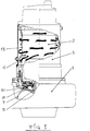
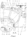
- Fig 1 shows the principle for a cooling system according to the invention, while Fig 2 and 3 show the impeller from two views.
- FIG. 1 stands for a pump housing, 2 an electric motor surrounded by a cooling jacket 3 having vanes 4 for circulation.
- 5 stands for a pump impeller having inlet 6, main vanes 7 and back vanes 8.
- 9 stands for a ring formed part, 10 a part of the pump housing, 11 a slot, 12 axially directed grooves and 13 an exhaust pipe.
- Fig 1 shows the principle for cooling of the motor 2 by help of pumped liquid.
- the latter is fed through a narrow slot 11 between the impeller 5 and the pump housing 1.
- the liquid is circulated around the motor within a slot under the jacket 3.
- the exhaust pipe 13 direct air bubbles from the upper part of the jacket where the air is compressed.
- Fig 2 there is an axially directed slot 11 between a ring formed extension 9 on the impeller 5 and a corresponding extension 10 at the pump housing 1. Liquid is fed through this slot into the room behind, above the impeller.
- the back vanes 8 operate in said room to obtain the circulation (C) of cooling medium around the motor. As is shown in Fig 3, the vanes start a distance outwards from the center of the impeller and end at the ring formed extension 9 previously mentioned.
- the air present in the cooling water room at pump start which makes the pumping of the cooling medium more difficult, is collected at the back sides of the vanes 8 and particularly at their tips.
- An effective deaeration is, according to the invention, obtained by help of the ring formed extension 9 being provided with axially directed grooves 12 in front of the back sides of the vanes 5.
- the air bubbles are directed outwards to the pumped medium (D) and thus constitute no hinderance to the pumping of the cooling medium. Tests have proven that the evacuation time has been reduced to one third of the normal time. As the grooves 12 are arranged at the tips of the vanes, there is no risk that pollutions from the pumped medium should enter the broadened slot.
Landscapes
- Engineering & Computer Science (AREA)
- Mechanical Engineering (AREA)
- General Engineering & Computer Science (AREA)
- Physics & Mathematics (AREA)
- Thermal Sciences (AREA)
- Structures Of Non-Positive Displacement Pumps (AREA)
- Motor Or Generator Cooling System (AREA)
Abstract
Description
- The invention concerns an impeller of centrifugal type to be used in a pump meant for pumping of liquids containing solid pollutions.
- A common pump type is the so-called submersible pump where the pump and an electric motor as a unit is submersed in the pumped medium, the motor normally obtaining its cooling directly from the surrounding, pumped medium. If however, the level of the liquid decreases such that the motor is surrounded by air, the cooling may be insufficient and therefore the motor is often provided with an internal cooling system where the pumped medium is used. An example of such a solution is shown in the Swedish Patent No 367 465.
- As the pumped medium often contains pollutions, said patent suggests a narrow slot to be arranged between the impeller and the pump housing through which comparatively clean water is fed into the cooling water room between the pump and the motor, where the water is circulated by help of vanes at the back of the impeller. The slot prevents pollutions from going into the cooling water room thus diminishing the risks for clogging of the cooling channels around the motor.
- According to a further development of subject patent, vanes are arranged within the cooling jacket which transport the cooling liquid a distance upwards thus obtaining a cooling of the entire motor.
- At pump start air bubbles may collect within the cooling water room at the back of the impeller. This may cause that the vanes will not be able to grip the liquid and thus no circulation is obtained.
- According to the invention the problem with the air bubbles is solved by a specific design of the impeller as stated in the claim.
- The invention is described more closely below with reference to the enclosed drawings.
- Fig 1 shows the principle for a cooling system according to the invention, while Fig 2 and 3 show the impeller from two views.
- In the
drawings 1 stands for a pump housing, 2 an electric motor surrounded by acooling jacket 3 havingvanes 4 for circulation. 5 stands for a pump impeller having inlet 6,main vanes 7 andback vanes 8. 9 stands for a ring formed part, 10 a part of the pump housing, 11 a slot, 12 axially directed grooves and 13 an exhaust pipe. - Fig 1 shows the principle for cooling of the
motor 2 by help of pumped liquid. The latter is fed through anarrow slot 11 between theimpeller 5 and thepump housing 1. The liquid is circulated around the motor within a slot under thejacket 3. Theexhaust pipe 13 direct air bubbles from the upper part of the jacket where the air is compressed. - As is shown in Fig 2 there is an axially directed
slot 11 between a ring formedextension 9 on theimpeller 5 and acorresponding extension 10 at thepump housing 1. Liquid is fed through this slot into the room behind, above the impeller. - The
back vanes 8 operate in said room to obtain the circulation (C) of cooling medium around the motor. As is shown in Fig 3, the vanes start a distance outwards from the center of the impeller and end at the ring formedextension 9 previously mentioned. - The air present in the cooling water room at pump start which makes the pumping of the cooling medium more difficult, is collected at the back sides of the
vanes 8 and particularly at their tips. An effective deaeration is, according to the invention, obtained by help of the ring formedextension 9 being provided with axially directedgrooves 12 in front of the back sides of thevanes 5. By help of these limited broadenings of the slot the air bubbles are directed outwards to the pumped medium (D) and thus constitute no hinderance to the pumping of the cooling medium. Tests have proven that the evacuation time has been reduced to one third of the normal time. As thegrooves 12 are arranged at the tips of the vanes, there is no risk that pollutions from the pumped medium should enter the broadened slot.
Claims (1)
- A centrifugal pump impeller for pumping liquids containing solid bodies, comprising a central, axially directed inlet and a number of radially or tangentially directed vanes which between themselves create the outlet of the impeller, said impeller at its back side being provided with a number of back vanes for pumping of cooling liquid to be circulated around the electric motor driving the pump, said cooling liquid being fed through a circular slot at or near the circumference of the impeller, characterised in that the slot (11) is axially directed and is created by a ring formed extension (9) on the back side of the impeller (5) and a non-rotary part (10) of the pump housing (1) situated radially inward of said extension (9), that the tips of the back vanes (8) are situated close to the extension (9) and that the latter is provided with axially directed grooves (12) at the vane tips which widen the slot (11) in these areas.
Applications Claiming Priority (2)
| Application Number | Priority Date | Filing Date | Title |
|---|---|---|---|
| SE9102518 | 1991-09-03 | ||
| SE9102518A SE469040B (en) | 1991-09-03 | 1991-09-03 | CENTRIFUGAL PUMP WHEEL FOR PUMP INTENDED TO PUMP WATER SHOES CONTAINING SOLID PARTICLES |
Publications (2)
| Publication Number | Publication Date |
|---|---|
| EP0538212A1 true EP0538212A1 (en) | 1993-04-21 |
| EP0538212B1 EP0538212B1 (en) | 1997-11-19 |
Family
ID=20383603
Family Applications (1)
| Application Number | Title | Priority Date | Filing Date |
|---|---|---|---|
| EP92850179A Expired - Lifetime EP0538212B1 (en) | 1991-09-03 | 1992-07-24 | Pump impeller |
Country Status (9)
| Country | Link |
|---|---|
| US (1) | US5281088A (en) |
| EP (1) | EP0538212B1 (en) |
| JP (1) | JP2608662B2 (en) |
| AT (1) | ATE160428T1 (en) |
| AU (1) | AU646177B2 (en) |
| CA (1) | CA2077290C (en) |
| DE (1) | DE69223216T2 (en) |
| ES (1) | ES2109331T3 (en) |
| SE (1) | SE469040B (en) |
Cited By (9)
| Publication number | Priority date | Publication date | Assignee | Title |
|---|---|---|---|---|
| DE4431947A1 (en) * | 1993-09-25 | 1995-03-30 | Klein Schanzlin & Becker Ag | Fluid flow engine for particle containing medium - has wall surfaces formed to direct medium flow in regions of higher rotary fluid flow |
| WO1999027257A3 (en) * | 1997-11-25 | 1999-07-15 | Zakrytoe Aktsionernoe Obschest | Stage in a submerged multiple-stage pump |
| US5984629A (en) * | 1993-09-25 | 1999-11-16 | Ksb Aktiengesellscaft | Turbo-machine with reduced abrasive wear |
| RU2232297C2 (en) * | 2002-06-24 | 2004-07-10 | Рабинович Александр Исаакович | Centrifugal vortex pump stage |
| RU2281417C2 (en) * | 2004-10-06 | 2006-08-10 | Алексей Владимирович Трулев | Stage of multistage centrifugal oil-well pump |
| WO2011079892A1 (en) * | 2009-12-30 | 2011-07-07 | Grundfos Management A/S | Submersible pump |
| US10514042B2 (en) | 2013-06-21 | 2019-12-24 | Flow Control LLC | Debris removing impeller back vane |
| WO2021105047A1 (en) * | 2019-11-25 | 2021-06-03 | Robert Bosch Gmbh | Turbomachine |
| EP3978760A1 (en) * | 2020-10-02 | 2022-04-06 | Renner GmbH | Submersible centrifugal pump and impeller for same |
Families Citing this family (16)
| Publication number | Priority date | Publication date | Assignee | Title |
|---|---|---|---|---|
| US6623510B2 (en) * | 2000-12-07 | 2003-09-23 | Integrated Vascular Systems, Inc. | Closure device and methods for making and using them |
| US6719541B2 (en) | 2002-04-30 | 2004-04-13 | Northland/Scott Fetzer Company | Fan assembly with application to vacuum cleaners |
| DE102005034341A1 (en) * | 2005-07-22 | 2007-01-25 | Ksb Aktiengesellschaft | Submerged motor pump has cooling sleeve for drive motor supplied with fluid from pumping wheel with flow throttling gap to discharge chamber |
| US7628836B2 (en) * | 2006-05-08 | 2009-12-08 | Hamilton Sundstrand Corporation | Rotary drum separator system |
| AU2013202765B2 (en) * | 2007-05-21 | 2016-01-07 | Weir Minerals Australia Ltd | Improvements in and relating to pumps |
| CN105864054B (en) | 2007-05-21 | 2018-06-26 | 伟尔矿物澳大利亚私人有限公司 | A kind of impeller of pump with shaft |
| ATE511607T1 (en) * | 2009-02-26 | 2011-06-15 | Grundfos Management As | PUMP UNIT |
| LU91731B1 (en) * | 2010-09-13 | 2012-03-14 | Zenit Internat S A | Cooling systems for submersible pumps |
| DE102016110224B4 (en) * | 2015-06-03 | 2020-03-12 | Gea Tuchenhagen Gmbh | Centrifugal pump and impeller for a centrifugal pump |
| ITUB20152564A1 (en) * | 2015-07-28 | 2017-01-28 | Nuovo Pignone Tecnologie Srl | MOTORCOMPRESSOR AND METHOD TO IMPROVE THE EFFICIENCY OF A MOTOR-COMPRESSOR |
| DE102015119098B4 (en) * | 2015-11-06 | 2019-03-21 | Pierburg Gmbh | Control arrangement for a mechanically controllable coolant pump of an internal combustion engine |
| DE102015119095B4 (en) | 2015-11-06 | 2019-03-21 | Pierburg Gmbh | Coolant pump for an internal combustion engine |
| DE102015119097B4 (en) | 2015-11-06 | 2019-03-21 | Pierburg Gmbh | Coolant pump for an internal combustion engine |
| EP3324052A1 (en) * | 2016-11-18 | 2018-05-23 | Sogefi Air & Cooling (SAS) | Impeller for a fluid pump |
| DK201770269A1 (en) * | 2017-04-18 | 2018-12-06 | Spx Flow Technology Danmark A/S | A pump for pumping heat-sensitive fluids |
| CN111794991B (en) * | 2020-09-08 | 2021-01-05 | 山东天瑞重工有限公司 | Magnetic suspension double round air-blower |
Citations (4)
| Publication number | Priority date | Publication date | Assignee | Title |
|---|---|---|---|---|
| DE1528862A1 (en) * | 1965-04-30 | 1970-04-23 | Stenberg Flygt Ab | Sewage pump or the like. |
| US3897178A (en) * | 1972-09-09 | 1975-07-29 | Frankl & Kirchner | Pumping system |
| US4349322A (en) * | 1978-02-14 | 1982-09-14 | Staehle Martin | Cooling a motor of a centrifugal pump for conveying liquids with deposited solids |
| US4523899A (en) * | 1982-12-15 | 1985-06-18 | Ebara Corporation | Submergible motor pump assembly |
Family Cites Families (10)
| Publication number | Priority date | Publication date | Assignee | Title |
|---|---|---|---|---|
| US1967316A (en) * | 1930-11-03 | 1934-07-24 | Hobart Mfg Co | Pump |
| DE712462C (en) * | 1939-05-04 | 1941-10-20 | A W Mackensen Maschinenfabrik | Self-priming circulation pump |
| US2349731A (en) * | 1942-03-20 | 1944-05-23 | Ingersoll Rand Co | Centrifugal pump |
| US2649050A (en) * | 1950-02-02 | 1953-08-18 | Dunlop Tire & Rubber Corp | Centrifugal pump |
| JPS5362203A (en) * | 1976-11-13 | 1978-06-03 | Kubota Ltd | Flood-preventive device for underwater pump |
| US5076757A (en) * | 1981-01-29 | 1991-12-31 | Vaughan Co., Inc. | High head centrifugal slicing slurry pump |
| JPS59229092A (en) * | 1983-06-08 | 1984-12-22 | Toshiba Corp | Recirculation pump for nuclear reactor |
| US4527947A (en) * | 1984-02-17 | 1985-07-09 | Elliott Eric R | Seal-free impeller pump for fluids containing abrasive materials or the like |
| FR2583729B1 (en) * | 1985-06-20 | 1987-09-18 | Granger Maurice | SIMPLIFIED APPARATUS FOR SIMULTANEOUSLY DISPENSING AND CUTTING BANDS OF WOUND MATERIALS WITH AUTOMATIC CHANGING OF THE ROLLER IN SERVICE. |
| SU1528035A1 (en) * | 1987-02-18 | 1994-10-30 | А.И. Золотарь | Centrifugal pump |
-
1991
- 1991-09-03 SE SE9102518A patent/SE469040B/en not_active IP Right Cessation
-
1992
- 1992-07-24 AT AT92850179T patent/ATE160428T1/en not_active IP Right Cessation
- 1992-07-24 ES ES92850179T patent/ES2109331T3/en not_active Expired - Lifetime
- 1992-07-24 EP EP92850179A patent/EP0538212B1/en not_active Expired - Lifetime
- 1992-07-24 DE DE69223216T patent/DE69223216T2/en not_active Expired - Fee Related
- 1992-08-03 JP JP4206734A patent/JP2608662B2/en not_active Expired - Fee Related
- 1992-08-10 US US07/927,907 patent/US5281088A/en not_active Expired - Lifetime
- 1992-08-21 AU AU21221/92A patent/AU646177B2/en not_active Ceased
- 1992-09-01 CA CA002077290A patent/CA2077290C/en not_active Expired - Fee Related
Patent Citations (4)
| Publication number | Priority date | Publication date | Assignee | Title |
|---|---|---|---|---|
| DE1528862A1 (en) * | 1965-04-30 | 1970-04-23 | Stenberg Flygt Ab | Sewage pump or the like. |
| US3897178A (en) * | 1972-09-09 | 1975-07-29 | Frankl & Kirchner | Pumping system |
| US4349322A (en) * | 1978-02-14 | 1982-09-14 | Staehle Martin | Cooling a motor of a centrifugal pump for conveying liquids with deposited solids |
| US4523899A (en) * | 1982-12-15 | 1985-06-18 | Ebara Corporation | Submergible motor pump assembly |
Cited By (14)
| Publication number | Priority date | Publication date | Assignee | Title |
|---|---|---|---|---|
| DE4431947A1 (en) * | 1993-09-25 | 1995-03-30 | Klein Schanzlin & Becker Ag | Fluid flow engine for particle containing medium - has wall surfaces formed to direct medium flow in regions of higher rotary fluid flow |
| US5984629A (en) * | 1993-09-25 | 1999-11-16 | Ksb Aktiengesellscaft | Turbo-machine with reduced abrasive wear |
| WO1999027257A3 (en) * | 1997-11-25 | 1999-07-15 | Zakrytoe Aktsionernoe Obschest | Stage in a submerged multiple-stage pump |
| RU2138691C1 (en) * | 1997-11-25 | 1999-09-27 | Рабинович Александр Исаакович | Stage of submersible multi-stage pump |
| EA001523B1 (en) * | 1997-11-25 | 2001-04-23 | Закрытое Акционерное Общество "Новомет-Пермь" | Stage in a submurged multiple-stage pump |
| US6368056B1 (en) | 1997-11-25 | 2002-04-09 | Zakrytoe Aktsionernoe Obschestvo “Novomet-Perm” | Stage in a submerged multiple-stage pump |
| RU2232297C2 (en) * | 2002-06-24 | 2004-07-10 | Рабинович Александр Исаакович | Centrifugal vortex pump stage |
| RU2281417C2 (en) * | 2004-10-06 | 2006-08-10 | Алексей Владимирович Трулев | Stage of multistage centrifugal oil-well pump |
| WO2011079892A1 (en) * | 2009-12-30 | 2011-07-07 | Grundfos Management A/S | Submersible pump |
| EP2348220A1 (en) * | 2009-12-30 | 2011-07-27 | Grundfos Management A/S | Immersion pump |
| US9234523B2 (en) | 2009-12-30 | 2016-01-12 | Grundfos Management A/S | Submersible pump |
| US10514042B2 (en) | 2013-06-21 | 2019-12-24 | Flow Control LLC | Debris removing impeller back vane |
| WO2021105047A1 (en) * | 2019-11-25 | 2021-06-03 | Robert Bosch Gmbh | Turbomachine |
| EP3978760A1 (en) * | 2020-10-02 | 2022-04-06 | Renner GmbH | Submersible centrifugal pump and impeller for same |
Also Published As
| Publication number | Publication date |
|---|---|
| JPH05195990A (en) | 1993-08-06 |
| EP0538212B1 (en) | 1997-11-19 |
| DE69223216T2 (en) | 1998-03-19 |
| CA2077290C (en) | 1995-06-20 |
| JP2608662B2 (en) | 1997-05-07 |
| US5281088A (en) | 1994-01-25 |
| DE69223216D1 (en) | 1998-01-02 |
| SE9102518D0 (en) | 1991-09-03 |
| AU646177B2 (en) | 1994-02-10 |
| SE9102518L (en) | 1993-03-04 |
| AU2122192A (en) | 1993-03-11 |
| ATE160428T1 (en) | 1997-12-15 |
| ES2109331T3 (en) | 1998-01-16 |
| SE469040B (en) | 1993-05-03 |
Similar Documents
| Publication | Publication Date | Title |
|---|---|---|
| EP0538212B1 (en) | Pump impeller | |
| EP0531267B1 (en) | Motor cooling device | |
| US5857841A (en) | Full-circumferential flow pump | |
| EP0252037A1 (en) | A seal device | |
| US5494403A (en) | Full-circumferential flow pump | |
| EP0395604A1 (en) | Centrifugal pump | |
| US5320489A (en) | Diffuser for a centrifugal pump | |
| EP0728949A1 (en) | Group of full-circumferential-flow pumps and method of manufacturing the same | |
| US4293288A (en) | Submersible pump housing | |
| US3680976A (en) | Centrifugal pump having leakage collection and draining means | |
| US4530643A (en) | Centrifugal pump impeller | |
| EP0597815B1 (en) | A pump housing device | |
| EP0649987B1 (en) | A pump housing for a rotary pump | |
| EP0648934B1 (en) | Full-circumferential flow pump | |
| US3126831A (en) | Motor-pump unit | |
| US3437045A (en) | Submersible pump | |
| EP0672832A1 (en) | Sealing device for pump impeller | |
| EP0359731A1 (en) | Impeller | |
| JP3052199B2 (en) | Centrifugal multistage pump | |
| RU2005217C1 (en) | Multistage axial-flow pump for handling heterogeneous media | |
| US3506374A (en) | Self-priming pump | |
| SU1765524A1 (en) | Multistage pump | |
| SU1094986A1 (en) | Centrifugal pump | |
| SU1008494A1 (en) | Sealed pump electric motor | |
| EP1085212A2 (en) | High-pressure centrifugal pump |
Legal Events
| Date | Code | Title | Description |
|---|---|---|---|
| PUAI | Public reference made under article 153(3) epc to a published international application that has entered the european phase |
Free format text: ORIGINAL CODE: 0009012 |
|
| AK | Designated contracting states |
Kind code of ref document: A1 Designated state(s): AT DE ES FR GB IT NL |
|
| 17P | Request for examination filed |
Effective date: 19930929 |
|
| 17Q | First examination report despatched |
Effective date: 19961115 |
|
| GRAG | Despatch of communication of intention to grant |
Free format text: ORIGINAL CODE: EPIDOS AGRA |
|
| GRAH | Despatch of communication of intention to grant a patent |
Free format text: ORIGINAL CODE: EPIDOS IGRA |
|
| GRAH | Despatch of communication of intention to grant a patent |
Free format text: ORIGINAL CODE: EPIDOS IGRA |
|
| GRAA | (expected) grant |
Free format text: ORIGINAL CODE: 0009210 |
|
| AK | Designated contracting states |
Kind code of ref document: B1 Designated state(s): AT DE ES FR GB IT NL |
|
| REF | Corresponds to: |
Ref document number: 160428 Country of ref document: AT Date of ref document: 19971215 Kind code of ref document: T |
|
| ITF | It: translation for a ep patent filed | ||
| REF | Corresponds to: |
Ref document number: 69223216 Country of ref document: DE Date of ref document: 19980102 |
|
| REG | Reference to a national code |
Ref country code: ES Ref legal event code: FG2A Ref document number: 2109331 Country of ref document: ES Kind code of ref document: T3 |
|
| ET | Fr: translation filed | ||
| PLBE | No opposition filed within time limit |
Free format text: ORIGINAL CODE: 0009261 |
|
| 26N | No opposition filed | ||
| REG | Reference to a national code |
Ref country code: GB Ref legal event code: IF02 |
|
| PGFP | Annual fee paid to national office [announced via postgrant information from national office to epo] |
Ref country code: AT Payment date: 20030711 Year of fee payment: 12 |
|
| PGFP | Annual fee paid to national office [announced via postgrant information from national office to epo] |
Ref country code: NL Payment date: 20030730 Year of fee payment: 12 |
|
| PGFP | Annual fee paid to national office [announced via postgrant information from national office to epo] |
Ref country code: ES Payment date: 20030813 Year of fee payment: 12 |
|
| PG25 | Lapsed in a contracting state [announced via postgrant information from national office to epo] |
Ref country code: AT Free format text: LAPSE BECAUSE OF NON-PAYMENT OF DUE FEES Effective date: 20040724 |
|
| PG25 | Lapsed in a contracting state [announced via postgrant information from national office to epo] |
Ref country code: ES Free format text: LAPSE BECAUSE OF NON-PAYMENT OF DUE FEES Effective date: 20040726 |
|
| PG25 | Lapsed in a contracting state [announced via postgrant information from national office to epo] |
Ref country code: NL Free format text: LAPSE BECAUSE OF NON-PAYMENT OF DUE FEES Effective date: 20050201 |
|
| NLV4 | Nl: lapsed or anulled due to non-payment of the annual fee |
Effective date: 20050201 |
|
| REG | Reference to a national code |
Ref country code: ES Ref legal event code: FD2A Effective date: 20040726 |
|
| PGFP | Annual fee paid to national office [announced via postgrant information from national office to epo] |
Ref country code: DE Payment date: 20080718 Year of fee payment: 17 |
|
| PGFP | Annual fee paid to national office [announced via postgrant information from national office to epo] |
Ref country code: IT Payment date: 20080726 Year of fee payment: 17 Ref country code: FR Payment date: 20080630 Year of fee payment: 17 |
|
| PGFP | Annual fee paid to national office [announced via postgrant information from national office to epo] |
Ref country code: GB Payment date: 20080723 Year of fee payment: 17 |
|
| GBPC | Gb: european patent ceased through non-payment of renewal fee |
Effective date: 20090724 |
|
| REG | Reference to a national code |
Ref country code: FR Ref legal event code: ST Effective date: 20100331 |
|
| PG25 | Lapsed in a contracting state [announced via postgrant information from national office to epo] |
Ref country code: FR Free format text: LAPSE BECAUSE OF NON-PAYMENT OF DUE FEES Effective date: 20090731 |
|
| PG25 | Lapsed in a contracting state [announced via postgrant information from national office to epo] |
Ref country code: GB Free format text: LAPSE BECAUSE OF NON-PAYMENT OF DUE FEES Effective date: 20090724 |
|
| PG25 | Lapsed in a contracting state [announced via postgrant information from national office to epo] |
Ref country code: DE Free format text: LAPSE BECAUSE OF NON-PAYMENT OF DUE FEES Effective date: 20100202 |
|
| PG25 | Lapsed in a contracting state [announced via postgrant information from national office to epo] |
Ref country code: IT Free format text: LAPSE BECAUSE OF NON-PAYMENT OF DUE FEES Effective date: 20090724 |