EP3978253B1 - Recording apparatus - Google Patents
Recording apparatus Download PDFInfo
- Publication number
- EP3978253B1 EP3978253B1 EP21198837.3A EP21198837A EP3978253B1 EP 3978253 B1 EP3978253 B1 EP 3978253B1 EP 21198837 A EP21198837 A EP 21198837A EP 3978253 B1 EP3978253 B1 EP 3978253B1
- Authority
- EP
- European Patent Office
- Prior art keywords
- flow passage
- ink
- valve
- recording head
- carriage
- Prior art date
- Legal status (The legal status is an assumption and is not a legal conclusion. Google has not performed a legal analysis and makes no representation as to the accuracy of the status listed.)
- Active
Links
Images








Classifications
-
- B—PERFORMING OPERATIONS; TRANSPORTING
- B41—PRINTING; LINING MACHINES; TYPEWRITERS; STAMPS
- B41J—TYPEWRITERS; SELECTIVE PRINTING MECHANISMS, i.e. MECHANISMS PRINTING OTHERWISE THAN FROM A FORME; CORRECTION OF TYPOGRAPHICAL ERRORS
- B41J2/00—Typewriters or selective printing mechanisms characterised by the printing or marking process for which they are designed
- B41J2/005—Typewriters or selective printing mechanisms characterised by the printing or marking process for which they are designed characterised by bringing liquid or particles selectively into contact with a printing material
- B41J2/01—Ink jet
- B41J2/17—Ink jet characterised by ink handling
- B41J2/175—Ink supply systems ; Circuit parts therefor
- B41J2/17596—Ink pumps, ink valves
-
- B—PERFORMING OPERATIONS; TRANSPORTING
- B41—PRINTING; LINING MACHINES; TYPEWRITERS; STAMPS
- B41J—TYPEWRITERS; SELECTIVE PRINTING MECHANISMS, i.e. MECHANISMS PRINTING OTHERWISE THAN FROM A FORME; CORRECTION OF TYPOGRAPHICAL ERRORS
- B41J2/00—Typewriters or selective printing mechanisms characterised by the printing or marking process for which they are designed
- B41J2/005—Typewriters or selective printing mechanisms characterised by the printing or marking process for which they are designed characterised by bringing liquid or particles selectively into contact with a printing material
- B41J2/01—Ink jet
- B41J2/17—Ink jet characterised by ink handling
- B41J2/18—Ink recirculation systems
-
- B—PERFORMING OPERATIONS; TRANSPORTING
- B41—PRINTING; LINING MACHINES; TYPEWRITERS; STAMPS
- B41J—TYPEWRITERS; SELECTIVE PRINTING MECHANISMS, i.e. MECHANISMS PRINTING OTHERWISE THAN FROM A FORME; CORRECTION OF TYPOGRAPHICAL ERRORS
- B41J25/00—Actions or mechanisms not otherwise provided for
- B41J25/001—Mechanisms for bodily moving print heads or carriages parallel to the paper surface
Definitions
- the present disclosure relates to a recording apparatus that records an image.
- Japanese Patent Application Laid-Open No. 2010-247401 discusses a configuration in which two tubes are coupled to both ends of a recording head in a moving direction in a manner forming a loop shape, so as to prevent ink that has moved in the tubes from flowing into the recording head and increasing the pressure in the recording head. With this configuration, a pressure rise in the recording head can be suppressed by distributing the movement of ink in the tubes due to the inertia force in tube directions that are opposite to the recording head.
- US 2011/115844 A1 discloses a recording apparatus comprising a tank configured to contain liquid to be supplied to a recording head and a flow passage configured to supply liquid from the tank to the recording head.
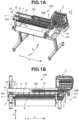
- An arrow Y indicates a right-left direction (width direction) in the front view of the recording apparatus 100, "L” corresponds to a left side, and “R” corresponds to a right side.
- An arrow Z indicates a top-bottom direction of the recording apparatus 100.
- a rolled sheet 1 serving as a recording medium is placed in a sheet feed portion that is provided at the front side of the recording apparatus 100.
- the sheet 1 fed into the recording apparatus 100 is conveyed to a position opposed to the recording unit (recording head 2) in a state where the sheet 1 is nipped between a conveyance roller 4 and a pinch roller 9.
- the conveyance roller 4 is rotationally driven, and the pinch roller 9 rotates following the conveyance roller 4.
- the recording head 2 includes a unit (e.g., a heating resistance element) that generates thermal energy as an energy used to eject ink, and uses a method for causing a state change (film boiling) in ink by the thermal energy.
- a unit e.g., a heating resistance element
- a state change film boiling
- higher-density higher-precision image recording can be achieved.
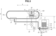
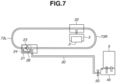
- FIG. 3 is a conceptual schematic diagram illustrating a flow passage for ink of a single color.
- a reserve tank 45 that is fixed to the recording apparatus 100 is disposed below each of the ink tanks 5 that are detachably mounted on the recording apparatus 100 by a user. Further, an ink supply path 46 for supplying ink from the ink tank 5 to the reserve tank 45 and an air introduction path 47 for introducing air from the reserve tank 45 to the ink tank 5 are provided between the ink tank 5 and the reserve tank 45.
- the reserve tank 45 includes an atmosphere communication portion 48 for communicating with the atmosphere and is opened to the atmosphere.
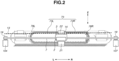
- ink is supplied from the ink tank 5 to the recording head 2 in two directions through the movable tube 73R and the movable tube 73L in the present exemplary embodiment.
- the movable tubes 73R and 73L are connected to the carriage joint 22 and the recording head 2 from different directions in a movement direction (Y-direction) of the carriage 3.
- the movable tubes 73R and 73L form a loop ink flow passage, which extends on a Y-Z plane defined by the Y-direction and the Z-direction (gravitational direction), for each color of ink.
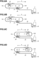
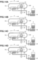
- Fig. 5C illustrates a state where the carriage 3 is decelerated to change the moving direction from the reverse direction to the forward direction at the R-side end.
- Fig. 5D illustrates a state where the carriage 3 is accelerated to move toward the L-side after the reverse movement.
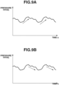
- the pressure in the recording head 2 that has increased due to the acceleration or deceleration at the L-side end gradually decreases as the pressure is restored to the level corresponding to the water head difference while the carriage 3 is moving in the reverse direction from the L-side to the R-side at a constant speed.
- the ink is moved due to the inertia force, which causes the pressure in the recording head 2 to increase again.
- FIG. 13A, 13B, and 13C each illustrate another example of the layout of the adjustment valve 24.
- Fig. 13A illustrates an example where the adjustment valve 24 is disposed on the movable tube 73R side in the fixed portion joint 21.
- Fig. 13B illustrates an example where the adjustment valve 24 is disposed on the movable tube 73L side in the carriage joint 22.
- Fig. 13C illustrates an example where the adjustment valve 24 is disposed on the movable tube 73R side in the carriage joint 22.
- the flow rate of ink that flows toward the recording head 2 from one direction can be limited.
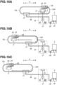
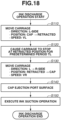
- step S 120 the carriage 3 is caused to stop at the L-side end for a predetermined period TL. Then, as illustrated in Fig. 16C , the most of ink in the movable tube 73R is moved downward by gravity and reaches the movable tube 73L side.
- the predetermined period TL for which the carriage 3 stops at the L-side end is set depending on a period required for the ink in the movable tube 73R to move into the movable tube 73L. In the present exemplary embodiment, two minutes are set to the predetermined period TL for which the carriage 3 is caused to stop. A position where the carriage 3 stops at the L-side end is also referred to as a retracted position.
- a structure of the adjustment valve 24 different from that in the first exemplary embodiment will be described with reference to Figs. 19 to 22B .
- the adjustment valve 24 is provided in the carriage joint 22.
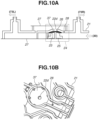
- Fig. 19 is a top perspective view illustrating the configuration of the carriage joint 22 according to the second exemplary embodiment.
- a connection portion 22a is connected to the movable tube 73R.
- a connection portion 22b is connected to the movable tube 73L.
- a connection portion 22c is connected to the carriage tube 33.
- connection portions 22a to 22c are provided for each color of ink.
- the adjustment valve 24 is formed for each flow passage in the carriage joint 22.
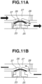
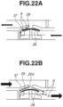
- Figs. 22A and 22B are enlarged schematic sectional views each illustrating a portion of the adjustment valve 24 illustrated in Figs. 20A and 20B .
- Fig. 22A illustrates a state where ink flows in the direction toward the recording head 2 from the movable tube 73R.
- ink if ink is to flow toward the recording head 2, the flow of ink brings the valve sheet 26 into close contact with the valve receiving portion 37.
- the adjustment valve groove 29 provided in the valve receiving portion 37 is not in close contact with the valve sheet 26, and thus ink flows through the portion corresponding to the adjustment valve groove 29.
- the adjustment valve groove 29 is provided on the recording head 2 side of the flow passage hole 22d, and thus the ink flows toward the recording head 2 while passing through the portion below the valve sheet 26.
- This flow of ink causes a force to act in the direction in which the valve sheet 26 is brought into closer contact with the valve receiving portion 37.
- the diameter of the adjustment valve groove 29 is smaller than those of the other flow passages, a pressure loss occurs when ink passes through the adjustment valve groove 29, and thus the flow rate is limited. Accordingly, the flow rate can be controlled so that the flow rate of ink that flows toward the recording head 2 can be decreased by providing the adjustment valve groove 29 instead of the branch flow passage 28 according to the first exemplary embodiment. Therefore, a pressure rise in the recording head 2 can be suppressed like in the first exemplary embodiment.
- Fig. 22B illustrates a state where ink flows in the direction toward the movable tube 73R from the recording head 2.
- the valve sheet 26 is apart from the valve receiving portion 37 and ink flows in the gap formed between the valve sheet 26 and the valve receiving portion 37.
- gas dissolved in ink can appear as air bubbles in the ink flow passage due to a change in temperature or atmospheric pressure.
- the air bubbles are more likely to be trapped in a narrower flow passage, and the air bubbles trapped in the narrower flow passage generate a resistance when ink flows and, as a result, inhibit the flow of ink.
- air bubbles A are trapped in the adjustment valve groove 29 in a state where the adjustment valve 24 is closed.
- the valve sheet 26 is pressed down and the ink flow passage is enlarged, thereby allowing the trapped air bubbles A to flow.
- Embodiment(s) of the present disclosure can also be realized by a computer of a system or apparatus that reads out and executes computer executable instructions (e.g., one or more programs) recorded on a storage medium (which may also be referred to more fully as a 'non-transitory computer-readable storage medium') to perform the functions of one or more of the above-described embodiment(s) and/or that includes one or more circuits (e.g., application specific integrated circuit (ASIC)) for performing the functions of one or more of the above-described embodiment(s), and by a method performed by the computer of the system or apparatus by, for example, reading out and executing the computer executable instructions from the storage medium to perform the functions of one or more of the above-described embodiment(s) and/or controlling the one or more circuits to perform the functions of one or more of the above-described embodiment(s).
- computer executable instructions e.g., one or more programs
- a storage medium which may also be referred to more fully as
- the computer may include one or more processors (e.g., central processing unit (CPU), micro processing unit (MPU)) and may include a network of separate computers or separate processors to read out and execute the computer executable instructions.
- the computer executable instructions may be provided to the computer, for example, from a network or the storage medium.
- the storage medium may include, for example, one or more of a hard disk, a random-access memory (RAM), a read-only memory (ROM), a storage of distributed computing systems, an optical disk (such as a compact disc (CD), digital versatile disc (DVD), or Blu-ray Disc (BD) TM ) , a flash memory device, a memory card, and the like.
Landscapes
- Ink Jet (AREA)
Applications Claiming Priority (1)
| Application Number | Priority Date | Filing Date | Title |
|---|---|---|---|
| JP2020166312A JP7566556B2 (ja) | 2020-09-30 | 2020-09-30 | 記録装置 |
Publications (2)
| Publication Number | Publication Date |
|---|---|
| EP3978253A1 EP3978253A1 (en) | 2022-04-06 |
| EP3978253B1 true EP3978253B1 (en) | 2024-07-03 |
Family
ID=77951525
Family Applications (1)
| Application Number | Title | Priority Date | Filing Date |
|---|---|---|---|
| EP21198837.3A Active EP3978253B1 (en) | 2020-09-30 | 2021-09-24 | Recording apparatus |
Country Status (5)
| Country | Link |
|---|---|
| US (1) | US12220925B2 (enExample) |
| EP (1) | EP3978253B1 (enExample) |
| JP (1) | JP7566556B2 (enExample) |
| KR (1) | KR102819510B1 (enExample) |
| CN (1) | CN114312009B (enExample) |
Family Cites Families (36)
| Publication number | Priority date | Publication date | Assignee | Title |
|---|---|---|---|---|
| JPS57115350A (en) | 1981-01-09 | 1982-07-17 | Matsushita Electric Ind Co Ltd | Liquid injecting device |
| JPS5896562A (ja) * | 1981-12-04 | 1983-06-08 | Matsushita Electric Ind Co Ltd | インク供給装置 |
| JPS58158261A (ja) * | 1982-03-16 | 1983-09-20 | Matsushita Electric Ind Co Ltd | 液体供給素子 |
| JPS60115452A (ja) * | 1983-11-26 | 1985-06-21 | Matsushita Electric Ind Co Ltd | 液体噴射装置 |
| JPS62109653A (ja) * | 1985-11-08 | 1987-05-20 | Canon Inc | インクジエツト記録装置 |
| JP3029498B2 (ja) | 1992-02-26 | 2000-04-04 | キヤノン株式会社 | インクジェット記録装置 |
| US5751300A (en) * | 1994-02-04 | 1998-05-12 | Hewlett-Packard Company | Ink delivery system for a printer |
| WO1996034759A1 (en) * | 1995-05-04 | 1996-11-07 | Calcomp Inc. | Ink source positioner for an ink delivery system |
| US6106109A (en) * | 1997-03-03 | 2000-08-22 | Hewlett-Packard Company | Printer apparatus for periodic automated connection of ink supply valves with multiple inkjet printheads |
| JP3606282B2 (ja) * | 2001-11-12 | 2005-01-05 | セイコーエプソン株式会社 | 液体噴射装置 |
| JP2004114411A (ja) | 2002-09-25 | 2004-04-15 | Canon Inc | インク供給装置及びインク供給方法 |
| JP2005144954A (ja) * | 2003-11-18 | 2005-06-09 | Toshiba Tec Corp | インクジェット装置 |
| US7331664B2 (en) * | 2004-10-29 | 2008-02-19 | Hewlett-Packard Development Company, L.P. | Ink delivery system and a method for replacing ink |
| US20060209140A1 (en) * | 2005-03-15 | 2006-09-21 | Konica Minolta Holdings, Inc. | Inkjet recording apparatus |
| JP2008055646A (ja) * | 2006-08-29 | 2008-03-13 | Toshiba Tec Corp | インクジェット記録装置およびその記録装置のインク供給方法 |
| US20080158321A1 (en) * | 2006-12-28 | 2008-07-03 | Toshiba Tec Kabushiki Kaisha | Ink jet recording apparatus, ink supplying mechanism and ink jet recording method |
| JP5007644B2 (ja) * | 2007-10-01 | 2012-08-22 | ブラザー工業株式会社 | 液滴吐出装置 |
| AU2009263666A1 (en) * | 2008-06-24 | 2009-12-30 | Mastermind Co., Ltd. | Printing device |
| JP2010247401A (ja) | 2009-04-14 | 2010-11-04 | Canon Inc | 画像形成装置 |
| US8876269B2 (en) * | 2009-08-31 | 2014-11-04 | Roland Dg Corporation | Inkjet recording device, computer program for controlling the same, and method of using the same |
| JP5732898B2 (ja) * | 2011-02-21 | 2015-06-10 | セイコーエプソン株式会社 | 液体吐出装置 |
| JP5449296B2 (ja) | 2011-11-01 | 2014-03-19 | キヤノン株式会社 | インクジェット装置およびインクジェットヘッドユニット |
| JP5796459B2 (ja) * | 2011-11-07 | 2015-10-21 | セイコーエプソン株式会社 | 印刷装置、及び、ホワイトインク循環方法 |
| JP5994259B2 (ja) * | 2012-01-30 | 2016-09-21 | セイコーエプソン株式会社 | 液体噴射装置 |
| JP6139099B2 (ja) * | 2012-10-30 | 2017-05-31 | エスアイアイ・プリンテック株式会社 | 液体噴射ユニット、液体噴射ユニットの使用方法及び液体噴射装置 |
| JP2015009412A (ja) | 2013-06-27 | 2015-01-19 | 株式会社ミマキエンジニアリング | インクジェットプリンター |
| JP6361727B2 (ja) * | 2014-02-24 | 2018-07-25 | コニカミノルタ株式会社 | インクジェット記録装置 |
| JP6408775B2 (ja) | 2014-03-26 | 2018-10-17 | キヤノン株式会社 | 記録装置及びその検知方法 |
| JP6422367B2 (ja) * | 2014-04-30 | 2018-11-14 | キヤノン株式会社 | 液体供給装置、液体吐出装置、および液体供給方法 |
| JP6520170B2 (ja) | 2015-02-09 | 2019-05-29 | ブラザー工業株式会社 | 液体供給装置、及び液体供給方法 |
| JP7034586B2 (ja) * | 2016-01-08 | 2022-03-14 | キヤノン株式会社 | 液体吐出ヘッド及び液体吐出方法 |
| JP6949513B2 (ja) * | 2017-03-08 | 2021-10-13 | 東芝テック株式会社 | 循環装置及び液体吐出装置 |
| JP6661576B2 (ja) * | 2017-06-28 | 2020-03-11 | キヤノン株式会社 | インクジェット記録装置 |
| JP7040202B2 (ja) | 2018-03-26 | 2022-03-23 | ブラザー工業株式会社 | 液体吐出装置及びヘッドユニット |
| JP7031435B2 (ja) * | 2018-03-29 | 2022-03-08 | ブラザー工業株式会社 | 液体吐出装置 |
| JP7135677B2 (ja) | 2018-09-28 | 2022-09-13 | セイコーエプソン株式会社 | ヘッドユニット及び液体噴射装置 |
-
2020
- 2020-09-30 JP JP2020166312A patent/JP7566556B2/ja active Active
-
2021
- 2021-09-24 EP EP21198837.3A patent/EP3978253B1/en active Active
- 2021-09-27 KR KR1020210127054A patent/KR102819510B1/ko active Active
- 2021-09-27 CN CN202111132720.XA patent/CN114312009B/zh active Active
- 2021-09-28 US US17/488,086 patent/US12220925B2/en active Active
Also Published As
| Publication number | Publication date |
|---|---|
| JP7566556B2 (ja) | 2024-10-15 |
| EP3978253A1 (en) | 2022-04-06 |
| KR20220044120A (ko) | 2022-04-06 |
| KR102819510B1 (ko) | 2025-06-13 |
| US20220097405A1 (en) | 2022-03-31 |
| JP2022057857A (ja) | 2022-04-11 |
| CN114312009A (zh) | 2022-04-12 |
| CN114312009B (zh) | 2023-09-29 |
| US12220925B2 (en) | 2025-02-11 |
Similar Documents
| Publication | Publication Date | Title |
|---|---|---|
| US12083804B2 (en) | Inkjet printing apparatus and control method of the inkjet printing apparatus | |
| US11807018B2 (en) | Inkjet printing apparatus and tank | |
| CN100575101C (zh) | 记录装置及记录方法 | |
| JP6429727B2 (ja) | 記録装置 | |
| US12145362B2 (en) | Inkjet printing apparatus and controlling method | |
| JP2023101789A (ja) | 液体吐出装置および液体吐出装置の制御方法 | |
| JP5636823B2 (ja) | 画像形成装置 | |
| US10843480B2 (en) | Inkjet printing apparatus and control method of inkjet printing apparatus | |
| US12220925B2 (en) | Recording apparatus | |
| US12070952B2 (en) | Recording apparatus and control method therefor | |
| JP5344298B2 (ja) | 画像形成装置 | |
| JP2010052194A (ja) | 画像形成装置 | |
| JP7120328B2 (ja) | 廃液回収装置及びこれを備えたインクジェット記録装置 | |
| US20250303728A1 (en) | Inkjet recording apparatus | |
| JP2009126031A (ja) | インクジェット方式画像形成装置のインク吐出方法 | |
| JP2004358669A (ja) | インクジェット記録装置 | |
| US20240391246A1 (en) | Degassing device and inkjet recording apparatus | |
| US20260131575A1 (en) | Liquid ejecting apparatus, control method, and storage medium | |
| JP2024104189A (ja) | インクジェット印刷装置 | |
| JP2025107722A (ja) | プリンタ | |
| CN114312019A (zh) | 记录装置及保持容器 | |
| JP4945210B2 (ja) | インクジェット記録装置 | |
| JP2005225197A (ja) | 液体吐出性能維持方法及び液体吐出装置 |
Legal Events
| Date | Code | Title | Description |
|---|---|---|---|
| PUAI | Public reference made under article 153(3) epc to a published international application that has entered the european phase |
Free format text: ORIGINAL CODE: 0009012 |
|
| STAA | Information on the status of an ep patent application or granted ep patent |
Free format text: STATUS: THE APPLICATION HAS BEEN PUBLISHED |
|
| AK | Designated contracting states |
Kind code of ref document: A1 Designated state(s): AL AT BE BG CH CY CZ DE DK EE ES FI FR GB GR HR HU IE IS IT LI LT LU LV MC MK MT NL NO PL PT RO RS SE SI SK SM TR |
|
| STAA | Information on the status of an ep patent application or granted ep patent |
Free format text: STATUS: REQUEST FOR EXAMINATION WAS MADE |
|
| 17P | Request for examination filed |
Effective date: 20221006 |
|
| RBV | Designated contracting states (corrected) |
Designated state(s): AL AT BE BG CH CY CZ DE DK EE ES FI FR GB GR HR HU IE IS IT LI LT LU LV MC MK MT NL NO PL PT RO RS SE SI SK SM TR |
|
| GRAP | Despatch of communication of intention to grant a patent |
Free format text: ORIGINAL CODE: EPIDOSNIGR1 |
|
| STAA | Information on the status of an ep patent application or granted ep patent |
Free format text: STATUS: GRANT OF PATENT IS INTENDED |
|
| INTG | Intention to grant announced |
Effective date: 20240123 |
|
| GRAS | Grant fee paid |
Free format text: ORIGINAL CODE: EPIDOSNIGR3 |
|
| GRAA | (expected) grant |
Free format text: ORIGINAL CODE: 0009210 |
|
| STAA | Information on the status of an ep patent application or granted ep patent |
Free format text: STATUS: THE PATENT HAS BEEN GRANTED |
|
| AK | Designated contracting states |
Kind code of ref document: B1 Designated state(s): AL AT BE BG CH CY CZ DE DK EE ES FI FR GB GR HR HU IE IS IT LI LT LU LV MC MK MT NL NO PL PT RO RS SE SI SK SM TR |
|
| REG | Reference to a national code |
Ref country code: CH Ref legal event code: EP |
|
| REG | Reference to a national code |
Ref country code: DE Ref legal event code: R096 Ref document number: 602021015067 Country of ref document: DE |
|
| REG | Reference to a national code |
Ref country code: LT Ref legal event code: MG9D |
|
| REG | Reference to a national code |
Ref country code: NL Ref legal event code: MP Effective date: 20240703 |
|
| PG25 | Lapsed in a contracting state [announced via postgrant information from national office to epo] |
Ref country code: PT Free format text: LAPSE BECAUSE OF FAILURE TO SUBMIT A TRANSLATION OF THE DESCRIPTION OR TO PAY THE FEE WITHIN THE PRESCRIBED TIME-LIMIT Effective date: 20241104 |
|
| REG | Reference to a national code |
Ref country code: AT Ref legal event code: MK05 Ref document number: 1699441 Country of ref document: AT Kind code of ref document: T Effective date: 20240703 |
|
| PG25 | Lapsed in a contracting state [announced via postgrant information from national office to epo] |
Ref country code: NL Free format text: LAPSE BECAUSE OF FAILURE TO SUBMIT A TRANSLATION OF THE DESCRIPTION OR TO PAY THE FEE WITHIN THE PRESCRIBED TIME-LIMIT Effective date: 20240703 |
|
| PG25 | Lapsed in a contracting state [announced via postgrant information from national office to epo] |
Ref country code: PT Free format text: LAPSE BECAUSE OF FAILURE TO SUBMIT A TRANSLATION OF THE DESCRIPTION OR TO PAY THE FEE WITHIN THE PRESCRIBED TIME-LIMIT Effective date: 20241104 Ref country code: NL Free format text: LAPSE BECAUSE OF FAILURE TO SUBMIT A TRANSLATION OF THE DESCRIPTION OR TO PAY THE FEE WITHIN THE PRESCRIBED TIME-LIMIT Effective date: 20240703 |
|
| PG25 | Lapsed in a contracting state [announced via postgrant information from national office to epo] |
Ref country code: NO Free format text: LAPSE BECAUSE OF FAILURE TO SUBMIT A TRANSLATION OF THE DESCRIPTION OR TO PAY THE FEE WITHIN THE PRESCRIBED TIME-LIMIT Effective date: 20241003 |
|
| PG25 | Lapsed in a contracting state [announced via postgrant information from national office to epo] |
Ref country code: FI Free format text: LAPSE BECAUSE OF FAILURE TO SUBMIT A TRANSLATION OF THE DESCRIPTION OR TO PAY THE FEE WITHIN THE PRESCRIBED TIME-LIMIT Effective date: 20240703 Ref country code: PL Free format text: LAPSE BECAUSE OF FAILURE TO SUBMIT A TRANSLATION OF THE DESCRIPTION OR TO PAY THE FEE WITHIN THE PRESCRIBED TIME-LIMIT Effective date: 20240703 Ref country code: GR Free format text: LAPSE BECAUSE OF FAILURE TO SUBMIT A TRANSLATION OF THE DESCRIPTION OR TO PAY THE FEE WITHIN THE PRESCRIBED TIME-LIMIT Effective date: 20241004 |
|
| PG25 | Lapsed in a contracting state [announced via postgrant information from national office to epo] |
Ref country code: BG Free format text: LAPSE BECAUSE OF FAILURE TO SUBMIT A TRANSLATION OF THE DESCRIPTION OR TO PAY THE FEE WITHIN THE PRESCRIBED TIME-LIMIT Effective date: 20240703 |
|
| PG25 | Lapsed in a contracting state [announced via postgrant information from national office to epo] |
Ref country code: LV Free format text: LAPSE BECAUSE OF FAILURE TO SUBMIT A TRANSLATION OF THE DESCRIPTION OR TO PAY THE FEE WITHIN THE PRESCRIBED TIME-LIMIT Effective date: 20240703 |
|
| PG25 | Lapsed in a contracting state [announced via postgrant information from national office to epo] |
Ref country code: IS Free format text: LAPSE BECAUSE OF FAILURE TO SUBMIT A TRANSLATION OF THE DESCRIPTION OR TO PAY THE FEE WITHIN THE PRESCRIBED TIME-LIMIT Effective date: 20241103 Ref country code: AT Free format text: LAPSE BECAUSE OF FAILURE TO SUBMIT A TRANSLATION OF THE DESCRIPTION OR TO PAY THE FEE WITHIN THE PRESCRIBED TIME-LIMIT Effective date: 20240703 |
|
| PG25 | Lapsed in a contracting state [announced via postgrant information from national office to epo] |
Ref country code: HR Free format text: LAPSE BECAUSE OF FAILURE TO SUBMIT A TRANSLATION OF THE DESCRIPTION OR TO PAY THE FEE WITHIN THE PRESCRIBED TIME-LIMIT Effective date: 20240703 Ref country code: CZ Free format text: LAPSE BECAUSE OF FAILURE TO SUBMIT A TRANSLATION OF THE DESCRIPTION OR TO PAY THE FEE WITHIN THE PRESCRIBED TIME-LIMIT Effective date: 20240703 |
|
| PG25 | Lapsed in a contracting state [announced via postgrant information from national office to epo] |
Ref country code: ES Free format text: LAPSE BECAUSE OF FAILURE TO SUBMIT A TRANSLATION OF THE DESCRIPTION OR TO PAY THE FEE WITHIN THE PRESCRIBED TIME-LIMIT Effective date: 20240703 Ref country code: RS Free format text: LAPSE BECAUSE OF FAILURE TO SUBMIT A TRANSLATION OF THE DESCRIPTION OR TO PAY THE FEE WITHIN THE PRESCRIBED TIME-LIMIT Effective date: 20241003 |
|
| PG25 | Lapsed in a contracting state [announced via postgrant information from national office to epo] |
Ref country code: RS Free format text: LAPSE BECAUSE OF FAILURE TO SUBMIT A TRANSLATION OF THE DESCRIPTION OR TO PAY THE FEE WITHIN THE PRESCRIBED TIME-LIMIT Effective date: 20241003 Ref country code: PL Free format text: LAPSE BECAUSE OF FAILURE TO SUBMIT A TRANSLATION OF THE DESCRIPTION OR TO PAY THE FEE WITHIN THE PRESCRIBED TIME-LIMIT Effective date: 20240703 Ref country code: NO Free format text: LAPSE BECAUSE OF FAILURE TO SUBMIT A TRANSLATION OF THE DESCRIPTION OR TO PAY THE FEE WITHIN THE PRESCRIBED TIME-LIMIT Effective date: 20241003 Ref country code: LV Free format text: LAPSE BECAUSE OF FAILURE TO SUBMIT A TRANSLATION OF THE DESCRIPTION OR TO PAY THE FEE WITHIN THE PRESCRIBED TIME-LIMIT Effective date: 20240703 Ref country code: IS Free format text: LAPSE BECAUSE OF FAILURE TO SUBMIT A TRANSLATION OF THE DESCRIPTION OR TO PAY THE FEE WITHIN THE PRESCRIBED TIME-LIMIT Effective date: 20241103 Ref country code: HR Free format text: LAPSE BECAUSE OF FAILURE TO SUBMIT A TRANSLATION OF THE DESCRIPTION OR TO PAY THE FEE WITHIN THE PRESCRIBED TIME-LIMIT Effective date: 20240703 Ref country code: GR Free format text: LAPSE BECAUSE OF FAILURE TO SUBMIT A TRANSLATION OF THE DESCRIPTION OR TO PAY THE FEE WITHIN THE PRESCRIBED TIME-LIMIT Effective date: 20241004 Ref country code: FI Free format text: LAPSE BECAUSE OF FAILURE TO SUBMIT A TRANSLATION OF THE DESCRIPTION OR TO PAY THE FEE WITHIN THE PRESCRIBED TIME-LIMIT Effective date: 20240703 Ref country code: ES Free format text: LAPSE BECAUSE OF FAILURE TO SUBMIT A TRANSLATION OF THE DESCRIPTION OR TO PAY THE FEE WITHIN THE PRESCRIBED TIME-LIMIT Effective date: 20240703 Ref country code: CZ Free format text: LAPSE BECAUSE OF FAILURE TO SUBMIT A TRANSLATION OF THE DESCRIPTION OR TO PAY THE FEE WITHIN THE PRESCRIBED TIME-LIMIT Effective date: 20240703 Ref country code: BG Free format text: LAPSE BECAUSE OF FAILURE TO SUBMIT A TRANSLATION OF THE DESCRIPTION OR TO PAY THE FEE WITHIN THE PRESCRIBED TIME-LIMIT Effective date: 20240703 Ref country code: AT Free format text: LAPSE BECAUSE OF FAILURE TO SUBMIT A TRANSLATION OF THE DESCRIPTION OR TO PAY THE FEE WITHIN THE PRESCRIBED TIME-LIMIT Effective date: 20240703 |
|
| REG | Reference to a national code |
Ref country code: DE Ref legal event code: R097 Ref document number: 602021015067 Country of ref document: DE |
|
| PG25 | Lapsed in a contracting state [announced via postgrant information from national office to epo] |
Ref country code: RO Free format text: LAPSE BECAUSE OF FAILURE TO SUBMIT A TRANSLATION OF THE DESCRIPTION OR TO PAY THE FEE WITHIN THE PRESCRIBED TIME-LIMIT Effective date: 20240703 Ref country code: SM Free format text: LAPSE BECAUSE OF FAILURE TO SUBMIT A TRANSLATION OF THE DESCRIPTION OR TO PAY THE FEE WITHIN THE PRESCRIBED TIME-LIMIT Effective date: 20240703 Ref country code: DK Free format text: LAPSE BECAUSE OF FAILURE TO SUBMIT A TRANSLATION OF THE DESCRIPTION OR TO PAY THE FEE WITHIN THE PRESCRIBED TIME-LIMIT Effective date: 20240703 |
|
| PG25 | Lapsed in a contracting state [announced via postgrant information from national office to epo] |
Ref country code: MC Free format text: LAPSE BECAUSE OF FAILURE TO SUBMIT A TRANSLATION OF THE DESCRIPTION OR TO PAY THE FEE WITHIN THE PRESCRIBED TIME-LIMIT Effective date: 20240703 Ref country code: EE Free format text: LAPSE BECAUSE OF FAILURE TO SUBMIT A TRANSLATION OF THE DESCRIPTION OR TO PAY THE FEE WITHIN THE PRESCRIBED TIME-LIMIT Effective date: 20240703 |
|
| PG25 | Lapsed in a contracting state [announced via postgrant information from national office to epo] |
Ref country code: IT Free format text: LAPSE BECAUSE OF FAILURE TO SUBMIT A TRANSLATION OF THE DESCRIPTION OR TO PAY THE FEE WITHIN THE PRESCRIBED TIME-LIMIT Effective date: 20240703 Ref country code: SK Free format text: LAPSE BECAUSE OF FAILURE TO SUBMIT A TRANSLATION OF THE DESCRIPTION OR TO PAY THE FEE WITHIN THE PRESCRIBED TIME-LIMIT Effective date: 20240703 |
|
| REG | Reference to a national code |
Ref country code: CH Ref legal event code: PL |
|
| PLBE | No opposition filed within time limit |
Free format text: ORIGINAL CODE: 0009261 |
|
| STAA | Information on the status of an ep patent application or granted ep patent |
Free format text: STATUS: NO OPPOSITION FILED WITHIN TIME LIMIT |
|
| PG25 | Lapsed in a contracting state [announced via postgrant information from national office to epo] |
Ref country code: LU Free format text: LAPSE BECAUSE OF NON-PAYMENT OF DUE FEES Effective date: 20240924 |
|
| 26N | No opposition filed |
Effective date: 20250404 |
|
| REG | Reference to a national code |
Ref country code: BE Ref legal event code: MM Effective date: 20240930 |
|
| PG25 | Lapsed in a contracting state [announced via postgrant information from national office to epo] |
Ref country code: BE Free format text: LAPSE BECAUSE OF NON-PAYMENT OF DUE FEES Effective date: 20240930 |
|
| PG25 | Lapsed in a contracting state [announced via postgrant information from national office to epo] |
Ref country code: FR Free format text: LAPSE BECAUSE OF NON-PAYMENT OF DUE FEES Effective date: 20240930 |
|
| PG25 | Lapsed in a contracting state [announced via postgrant information from national office to epo] |
Ref country code: CH Free format text: LAPSE BECAUSE OF NON-PAYMENT OF DUE FEES Effective date: 20240930 |
|
| PG25 | Lapsed in a contracting state [announced via postgrant information from national office to epo] |
Ref country code: IE Free format text: LAPSE BECAUSE OF NON-PAYMENT OF DUE FEES Effective date: 20240924 |
|
| PG25 | Lapsed in a contracting state [announced via postgrant information from national office to epo] |
Ref country code: SE Free format text: LAPSE BECAUSE OF FAILURE TO SUBMIT A TRANSLATION OF THE DESCRIPTION OR TO PAY THE FEE WITHIN THE PRESCRIBED TIME-LIMIT Effective date: 20240703 |
|
| PGFP | Annual fee paid to national office [announced via postgrant information from national office to epo] |
Ref country code: DE Payment date: 20250820 Year of fee payment: 5 |
|
| PG25 | Lapsed in a contracting state [announced via postgrant information from national office to epo] |
Ref country code: CY Free format text: LAPSE BECAUSE OF FAILURE TO SUBMIT A TRANSLATION OF THE DESCRIPTION OR TO PAY THE FEE WITHIN THE PRESCRIBED TIME-LIMIT; INVALID AB INITIO Effective date: 20210924 |
|
| PG25 | Lapsed in a contracting state [announced via postgrant information from national office to epo] |
Ref country code: HU Free format text: LAPSE BECAUSE OF FAILURE TO SUBMIT A TRANSLATION OF THE DESCRIPTION OR TO PAY THE FEE WITHIN THE PRESCRIBED TIME-LIMIT; INVALID AB INITIO Effective date: 20210924 |
|
| GBPC | Gb: european patent ceased through non-payment of renewal fee |
Effective date: 20250924 |
|
| PG25 | Lapsed in a contracting state [announced via postgrant information from national office to epo] |
Ref country code: TR Free format text: LAPSE BECAUSE OF FAILURE TO SUBMIT A TRANSLATION OF THE DESCRIPTION OR TO PAY THE FEE WITHIN THE PRESCRIBED TIME-LIMIT Effective date: 20240703 |
|
| PG25 | Lapsed in a contracting state [announced via postgrant information from national office to epo] |
Ref country code: SI Free format text: LAPSE BECAUSE OF FAILURE TO SUBMIT A TRANSLATION OF THE DESCRIPTION OR TO PAY THE FEE WITHIN THE PRESCRIBED TIME-LIMIT Effective date: 20240703 |
|
| PG25 | Lapsed in a contracting state [announced via postgrant information from national office to epo] |
Ref country code: LT Free format text: LAPSE BECAUSE OF FAILURE TO SUBMIT A TRANSLATION OF THE DESCRIPTION OR TO PAY THE FEE WITHIN THE PRESCRIBED TIME-LIMIT Effective date: 20240703 |
|
| PG25 | Lapsed in a contracting state [announced via postgrant information from national office to epo] |
Ref country code: GB Free format text: LAPSE BECAUSE OF NON-PAYMENT OF DUE FEES Effective date: 20250924 |