EP3974736B1 - Motorlager und entfeuchter damit - Google Patents
Motorlager und entfeuchter damit Download PDFInfo
- Publication number
- EP3974736B1 EP3974736B1 EP20922477.3A EP20922477A EP3974736B1 EP 3974736 B1 EP3974736 B1 EP 3974736B1 EP 20922477 A EP20922477 A EP 20922477A EP 3974736 B1 EP3974736 B1 EP 3974736B1
- Authority
- EP
- European Patent Office
- Prior art keywords
- support body
- guide groove
- dehumidifier
- filter screen
- motor
- Prior art date
- Legal status (The legal status is an assumption and is not a legal conclusion. Google has not performed a legal analysis and makes no representation as to the accuracy of the status listed.)
- Active
Links
Images


Classifications
-
- F—MECHANICAL ENGINEERING; LIGHTING; HEATING; WEAPONS; BLASTING
- F24—HEATING; RANGES; VENTILATING
- F24F—AIR-CONDITIONING; AIR-HUMIDIFICATION; VENTILATION; USE OF AIR CURRENTS FOR SCREENING
- F24F3/00—Air-conditioning systems in which conditioned primary air is supplied from one or more central stations to distributing units in the rooms or spaces where it may receive secondary treatment; Apparatus specially designed for such systems
- F24F3/12—Air-conditioning systems in which conditioned primary air is supplied from one or more central stations to distributing units in the rooms or spaces where it may receive secondary treatment; Apparatus specially designed for such systems characterised by the treatment of the air otherwise than by heating and cooling
- F24F3/14—Air-conditioning systems in which conditioned primary air is supplied from one or more central stations to distributing units in the rooms or spaces where it may receive secondary treatment; Apparatus specially designed for such systems characterised by the treatment of the air otherwise than by heating and cooling by humidification; by dehumidification
-
- F—MECHANICAL ENGINEERING; LIGHTING; HEATING; WEAPONS; BLASTING
- F24—HEATING; RANGES; VENTILATING
- F24F—AIR-CONDITIONING; AIR-HUMIDIFICATION; VENTILATION; USE OF AIR CURRENTS FOR SCREENING
- F24F13/00—Details common to, or for air-conditioning, air-humidification, ventilation or use of air currents for screening
- F24F13/32—Supports for air-conditioning, air-humidification or ventilation units
-
- F—MECHANICAL ENGINEERING; LIGHTING; HEATING; WEAPONS; BLASTING
- F04—POSITIVE - DISPLACEMENT MACHINES FOR LIQUIDS; PUMPS FOR LIQUIDS OR ELASTIC FLUIDS
- F04D—NON-POSITIVE-DISPLACEMENT PUMPS
- F04D29/00—Details, component parts, or accessories
- F04D29/66—Combating cavitation, whirls, noise, vibration or the like; Balancing
- F04D29/661—Combating cavitation, whirls, noise, vibration or the like; Balancing especially adapted for elastic fluid pumps
- F04D29/668—Combating cavitation, whirls, noise, vibration or the like; Balancing especially adapted for elastic fluid pumps damping or preventing mechanical vibrations
-
- F—MECHANICAL ENGINEERING; LIGHTING; HEATING; WEAPONS; BLASTING
- F24—HEATING; RANGES; VENTILATING
- F24F—AIR-CONDITIONING; AIR-HUMIDIFICATION; VENTILATION; USE OF AIR CURRENTS FOR SCREENING
- F24F1/00—Room units for air-conditioning, e.g. separate or self-contained units or units receiving primary air from a central station
- F24F1/0007—Indoor units, e.g. fan coil units
- F24F1/0018—Indoor units, e.g. fan coil units characterised by fans
-
- F—MECHANICAL ENGINEERING; LIGHTING; HEATING; WEAPONS; BLASTING
- F24—HEATING; RANGES; VENTILATING
- F24F—AIR-CONDITIONING; AIR-HUMIDIFICATION; VENTILATION; USE OF AIR CURRENTS FOR SCREENING
- F24F1/00—Room units for air-conditioning, e.g. separate or self-contained units or units receiving primary air from a central station
- F24F1/0007—Indoor units, e.g. fan coil units
- F24F1/0083—Indoor units, e.g. fan coil units with dehumidification means
-
- F—MECHANICAL ENGINEERING; LIGHTING; HEATING; WEAPONS; BLASTING
- F24—HEATING; RANGES; VENTILATING
- F24F—AIR-CONDITIONING; AIR-HUMIDIFICATION; VENTILATION; USE OF AIR CURRENTS FOR SCREENING
- F24F13/00—Details common to, or for air-conditioning, air-humidification, ventilation or use of air currents for screening
- F24F13/20—Casings or covers
-
- F—MECHANICAL ENGINEERING; LIGHTING; HEATING; WEAPONS; BLASTING
- F24—HEATING; RANGES; VENTILATING
- F24F—AIR-CONDITIONING; AIR-HUMIDIFICATION; VENTILATION; USE OF AIR CURRENTS FOR SCREENING
- F24F13/00—Details common to, or for air-conditioning, air-humidification, ventilation or use of air currents for screening
- F24F13/22—Means for preventing condensation or evacuating condensate
- F24F13/222—Means for preventing condensation or evacuating condensate for evacuating condensate
-
- F—MECHANICAL ENGINEERING; LIGHTING; HEATING; WEAPONS; BLASTING
- F24—HEATING; RANGES; VENTILATING
- F24F—AIR-CONDITIONING; AIR-HUMIDIFICATION; VENTILATION; USE OF AIR CURRENTS FOR SCREENING
- F24F13/00—Details common to, or for air-conditioning, air-humidification, ventilation or use of air currents for screening
- F24F13/28—Arrangement or mounting of filters
-
- F—MECHANICAL ENGINEERING; LIGHTING; HEATING; WEAPONS; BLASTING
- F24—HEATING; RANGES; VENTILATING
- F24F—AIR-CONDITIONING; AIR-HUMIDIFICATION; VENTILATION; USE OF AIR CURRENTS FOR SCREENING
- F24F13/00—Details common to, or for air-conditioning, air-humidification, ventilation or use of air currents for screening
- F24F13/30—Arrangement or mounting of heat-exchangers
-
- F—MECHANICAL ENGINEERING; LIGHTING; HEATING; WEAPONS; BLASTING
- F24—HEATING; RANGES; VENTILATING
- F24F—AIR-CONDITIONING; AIR-HUMIDIFICATION; VENTILATION; USE OF AIR CURRENTS FOR SCREENING
- F24F3/00—Air-conditioning systems in which conditioned primary air is supplied from one or more central stations to distributing units in the rooms or spaces where it may receive secondary treatment; Apparatus specially designed for such systems
- F24F3/12—Air-conditioning systems in which conditioned primary air is supplied from one or more central stations to distributing units in the rooms or spaces where it may receive secondary treatment; Apparatus specially designed for such systems characterised by the treatment of the air otherwise than by heating and cooling
- F24F3/14—Air-conditioning systems in which conditioned primary air is supplied from one or more central stations to distributing units in the rooms or spaces where it may receive secondary treatment; Apparatus specially designed for such systems characterised by the treatment of the air otherwise than by heating and cooling by humidification; by dehumidification
- F24F3/1405—Air-conditioning systems in which conditioned primary air is supplied from one or more central stations to distributing units in the rooms or spaces where it may receive secondary treatment; Apparatus specially designed for such systems characterised by the treatment of the air otherwise than by heating and cooling by humidification; by dehumidification in which the humidity of the air is exclusively affected by contact with the evaporator of a closed-circuit cooling system or heat pump circuit
-
- H—ELECTRICITY
- H02—GENERATION; CONVERSION OR DISTRIBUTION OF ELECTRIC POWER
- H02K—DYNAMO-ELECTRIC MACHINES
- H02K5/00—Casings; Enclosures; Supports
-
- F—MECHANICAL ENGINEERING; LIGHTING; HEATING; WEAPONS; BLASTING
- F24—HEATING; RANGES; VENTILATING
- F24F—AIR-CONDITIONING; AIR-HUMIDIFICATION; VENTILATION; USE OF AIR CURRENTS FOR SCREENING
- F24F13/00—Details common to, or for air-conditioning, air-humidification, ventilation or use of air currents for screening
- F24F13/20—Casings or covers
- F24F2013/205—Mounting a ventilator fan therein
Definitions
- Document CN 209689080 U discloses a rear coaming assembly of a window type air conditioner and the window type air conditioner, and the rear coaming assembly comprises a rear coaming body which is provided with a ventilation opening; the motor support is arranged on one side of the rear coaming body and connected with the rear coaming body, at least part of the motor support is opposite to the ventilation opening, and an air passing hole is formed in the motor support so that airflow can flow into the ventilation opening through the air passing hole.
- Document US 2001/037630 A1 relates to a dehumidifier housing including a lower housing having a barrier part fitted vertically between a compressor and a water tank inside of a cabinet, a drain part formed in a horizontal direction above the barrier part for collecting condensate dehumidified at a heat exchanger and draining the water tank, and sidewalls formed at both sides of the barrier part and the drain part in a front and rear direction and supported on an inside of the cabinet, an upper housing having an orifice part with an air flow hole in a central portion, and a rim part around the orifice part in front and rear direction and supported on an inside of the cabinet, and coupling means for coupling the lower housing and the upper housing, thereby enhancing rigidity and dehumidifying effect.
- Document JP 2009168437 A discloses a fan support table for the outdoor unit includes the support plate on which the fan is placed inside a case body of the outdoor unit and a plurality of fixation rods supporting the lower part of the support plate and having both ends jointed to the upper part of the case body of the outdoor unit.
- the fixation rod is bent upwardly so that a distance between both end parts gradually increases as the fixation rod is extended upwardly.
- the present application seeks to solve at least one of the problems existing in the related art.
- the present application provides a motor support which may realize suspension of a motor, and is favorable to guaranteeing an air volume and reducing power consumption.
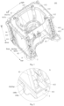
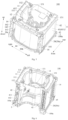
- a motor support includes: a support body; and a mounting rack hung below the support body by a connection member, wherein the mounting rack is configured to be mounted by a motor, wherein the motor support is for a dehumidifier, the motor of the fan of the dehumidifier is configured to be mounted at the mounting rack, and a condenser of the dehumidifier is configured to be supported at the lower side of the support body, and a stopper is formed at the support body and configured to abut against the condenser.
- the support body extends to be of a closed loop shape or an open loop shape.
- the motor support further includes a pillar supporting at a bottom of the support body.
- connection member includes a plurality of connection arms arranged at intervals along an extension direction of the support body, and an end of at least one of the connection arms connected to the support body has two sides in the length direction of the condenser provided with the stoppers respectively.
- the heat exchanger assembly includes a first heat exchanging part, a second heat exchanging part and a third heat exchanging part arranged along a circumferential direction of the housing, the first heat exchanging part is arranged opposite to the third heat exchanging part, the second heat exchanging part is connected between the first and third heat exchanging parts, one of the two side plates is provided at an end of the first heat exchanging part away from the second heat exchanging part, the other side plate is provided at an end of the third heat exchanging part away from the second heat exchanging part, the motor support further includes a pillar supporting between the support body and the water pan for support, and the pillar and the side plates are located at two opposite ends of the support body respectively.
- the first guide groove is formed at the support body.
- the first guide groove has a depth t1
- the second guide groove has a depth t2, t1>5 mm, and t2>5 mm.
- connection arm 131 may be configured as a sheet metal part.
- the motor support 1 further includes a pillar 14 for supporting a bottom of the support body 11, such that the pillar 14 may support the support body 11, thereby enhancing stability of the support body 11 and reducing shaking of the support body 11 during operation of the motor.
- the pillar 14 may be provided between the support body 11 and other components (for example, a water pan 2 described later) of the dehumidifier 100 for support, so as to guarantee stability of the motor support 1.
- the support body 11 extends to have the closed ring or open ring shape, there are a plurality of pillars 14, and the plurality of pillars 14 are arranged at intervals along the circumferential direction of the support body 11, so as to stably support the support body 11 by the pillars.
- the number of the pillar 14 may be one to be flexibly matched with actual applications.
- the evaporator 411 and the condenser 412 of the dehumidifier 100 are configured to be supported at the lower side of the support body 11, and shapes of the evaporator 411 and the condenser 412 may be matched with a shape of the support body 11, so as to effectively guarantee the stability of the support body 11;
- the upper surface of the support body 11 is provided with the convex rib 111 and/or the drainage hole 112, the convex rib 111 is configured to abut against the housing of the dehumidifier 100, the drainage hole 112 runs through the support body 11 in the up-down direction, and the stopper 15 is further formed at the support body 11, and configured to abut against the condenser 412, so as to guarantee assemblability of the support body 11, the evaporator 411 and the condenser 412.
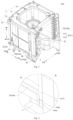
- the motor support 1 is configured as the motor support 1 according to the embodiments of the first aspect of the present application, the support body 11 is provided above the water pan 2, the mounting rack 12 is located between the support body 11 and the water pan 2 in the up-down direction, a motor of a fan of the dehumidifier 100 is mounted at the mounting rack 12, and the water pan 2 may be configured to collect moisture in air removed by the dehumidifier 100.
- the motor support 1 further includes a pillar 14 provided between the support body 11 and the water pan 2 for support, thus enhancing the stability of the support body 11 and reducing shaking thereof; and the pillar 14 and the two side plates 42 may be arranged at intervals in the extension direction of the support body 11 to stably support the support body 11.
- the filter screen assembly 3 when required to be cleaned or replaced, the filter screen assembly 3 may be drawn out from the first and second guide grooves 10, 20, thus quickly disassembling the filter screen assembly 3 and facilitating maintenance thereof; and when the filter screen assembly 3 is mounted, the upper and lower ends of the filter screen assembly 3 are inserted into the first and second guide grooves 10, 20 through one length end of the first guide groove 10 and one length end of the second guide groove 20 respectively, and a casing of the filter screen assembly 3 is moved to quickly mount the filter screen assembly 3, thus improving use convenience of the dehumidifier 100.
- the first guide groove 10 is formed at the support body 11, so as to ensure that the filter screen assembly 3 does not interfere with the motor on the mounting rack 12, guarantee mounting reliability of the filter screen assembly 3, achieve a smooth mounting goal of the filter screen assembly 3 and the motor, facilitate assembly of components in the housing into a whole, and guarantee structural stability of the dehumidifier 100.
Landscapes
- Engineering & Computer Science (AREA)
- Mechanical Engineering (AREA)
- General Engineering & Computer Science (AREA)
- Chemical & Material Sciences (AREA)
- Combustion & Propulsion (AREA)
- Power Engineering (AREA)
- Drying Of Gases (AREA)
Claims (15)
- Motorhalterung (1), umfassend
einen Halterungskörper (11);ein Montagegestell (12);wobei die Motorhalterung (1) für einen Luftentfeuchter (100) ist, ein Motor eines Gebläses des Luftentfeuchters (100) so konfiguriert ist, dass er auf dem Montagegestell (12) montiert ist;dadurch gekennzeichnet,das Montagegestell (12) mittels eines Verbindungselements (13) unter dem Halterungskörper (11) aufgehängt ist, wobei das Montagegestell (12) so konfiguriert ist, dass es den Motor montiert,ein Kondensator (412) des Luftentfeuchters (100) so konfiguriert ist, dass er an der Unterseite des Halterungskörpers (11) gehalten wird, ein Stopper (15) an dem Halterungskörper (11) ausgebildet ist und so konfiguriert ist, dass er an dem Kondensator (412) anliegt. - Motorhalterung (1) gemäß Anspruch 1, wobei sich der Halterungskörper (11) in Form einer geschlossenen Schleife oder in Form einer offenen Schleife erstreckt.
- Motorhalterung gemäß Anspruch 1 oder 2, wobei das Verbindungselement (13) eine Vielzahl von Verbindungsarmen (131) umfasst, die in einem Abstand entlang einer Umfangsrichtung des Halterungskörpers (11) angeordnet sind; und/oder
die Motorhalterung (1) ferner Folgendes umfasst:
eine Säule (14), die am Boden des Halterungskörpers (11) festhält. - Motorhalterung (1) gemäß einem der Ansprüche 1 bis 3, wobei ein Verdampfer (411) des Luftentfeuchters (100) so konfiguriert ist, dass er an einer Unterseite des Halterungskörpers (11) getragen wird, eine obere Fläche des Halterungskörpers (11) mit mindestens einer von einer konvexen Rippe (111) oder einem Drainageloch (112) versehen ist, wobei die konvexe Rippe (111) so konfiguriert ist, dass sie an einem Gehäuse des Luftentfeuchters (100) anliegt, das Drainageloch (112) durch den Halterungskörper (11) in einer Auf-Ab-Richtung verläuft.
- Motorhalterung (1) gemäß Anspruch 4, wobei, wenn der Stopper (15) an dem Halterungskörper (11) ausgebildet ist, der Stopper (15) Folgendes umfasst:ein erstes Anschlagelement (151), das so konfiguriert ist, dass es an einer Seite des Kondensators (412) in einer Breitenrichtung anliegt; und/oderein zweites Anschlagelement (152), das so konfiguriert ist, dass es an einer Seite des Kondensators (412) in einer Höhenrichtung anliegt.
- Motorhalterung (1) gemäß Anspruch 5, wobei, wenn der Stopper (15) an dem Halterungskörper (11) ausgebildet ist, eine Vielzahl von Stoppern (15) vorhanden ist, wobei die Vielzahl von Stoppern (15) so konfiguriert ist, dass diese in einem Abstand entlang einer Längsrichtung des Kondensators (412) angeordnet sind.
- Motorhalterung (1) gemäß Anspruch 6, wobei das Verbindungselement (13) eine Vielzahl von Verbindungsarmen (131) umfasst, die in einem Abstand entlang einer Erstreckungsrichtung des Halterungskörpers (11) angeordnet sind, ein Ende von mindestens einem der Verbindungsarme (131), das mit dem Halterungskörper (11) verbunden ist, zwei Seiten in der Längsrichtung des Kondensators (412) aufweist, wobei die beiden Seiten jeweils mit dem Stopper (15) versehen sind.
- Luftentfeuchter (100), umfassend:ein Gehäuse, das mit einem Lufteinlass ausgebildet ist;eine im Gehäuse vorgesehene Wasserwanne (2); undeine Motorhalterung (1) gemäß einem der Ansprüche 1 bis 6, wobei die Motorhalterung (1) in dem Gehäuse vorgesehen ist, der Halterungskörper (11) oberhalb der Wasserwanne (2) vorgesehen ist, sich das Montagegestell (12) zwischen dem Halterungskörper (11) und der Wasserwanne (2) in einer Auf-Ab-Richtung befindet, ein Motor eines Gebläses des Luftentfeuchters (100) an dem Montagegestell (12) montiert ist.
- Luftentfeuchter (100) gemäß Anspruch 8, wobei eine Wärmetauscheranordnung (4) in dem Gehäuse vorgesehen ist, die Wärmetauscheranordnung (4) oberhalb der Wasserwanne (2) vorgesehen ist und zwischen der Wasserwanne (2) und dem Halterungskörper (11) vorgesehen ist, die Wärmetauscheranordnung (4) einen Wärmetauscher (41) und zwei Seitenplatten (42) umfasst, der Wärmetauscher (41) einen Verdampfer (411) und einen Kondensator (412) umfasst, die aufeinanderfolgend von innen nach außen angeordnet sind, die beiden Seitenplatten (42) jeweils an zwei Enden des Wärmetauschers (41) vorgesehen und fest mit der Wasserwanne (2) verbunden sind, der Halterungskörper (11) an einer Oberseite des Wärmetauschers (41) gehalten und jeweils fest mit den beiden Seitenplatten (42) verbunden ist, wobei der Kondensator (412) stromabwärts des Verdampfers (411) in einer Luftstromrichtung angeordnet ist.
- Luftentfeuchter (100) gemäß Anspruch 9, wobei die Wärmetauscheranordnung (4) einen ersten Wärmetauscherteil (43), einen zweiten Wärmetauscherteil (44) und einen dritten Wärmetauscherteil (45) umfasst, die entlang einer Umfangsrichtung des Gehäuses angeordnet sind, wobei der erste Wärmetauscherteil (43) gegenüber dem dritten Wärmetauscherteil (45) angeordnet ist, der zweite Wärmetauscherteil (44) zwischen dem ersten Wärmetauscherteil (43) und dem dritten Wärmetauscherteil (45) verbunden ist, eine der beiden Seitenplatten (42) an einem vom zweiten Wärmetauscherteil (44) entfernten Ende des ersten Wärmetauscherteils (43) vorgesehen ist, die andere Seitenplatte (42) an einem vom zweiten Wärmetauscherteil (44) entfernten Ende des dritten Wärmetauscherteils (45) vorgesehen ist,die Motorhalterung (1) ferner eine Säule (14) umfasst, die zwischen dem Halterungskörper (11) und der Wasserwanne (2) hält,wobei sich die Säule (14) und die Seitenplatten (42) jeweils an zwei gegenüberliegenden Enden des Halterungskörpers (11) befinden.
- Luftentfeuchter (100) gemäß einem der Ansprüche 8 bis 10, ferner umfassend:
eine Filtersiebanordnung (3), die den Lufteinlass abdeckt, wobei eine erste Führungsnut (10) an der Motorhalterung (1) ausgebildet ist, eine zweite Führungsnut (20) an der Wasserwanne (2) ausgebildet ist, ein oberes Ende und ein unteres Ende der Filtersiebanordnung (3) jeweils durch ein Längsende der ersten Führungsnut (10) und ein Längsende der zweiten Führungsnut (20) hindurchgehen und in die erste Führungsnut (10) und die zweite Führungsnut (20) ziehbar eingesetzt sind. - Luftentfeuchter (100) gemäß Anspruch 11, wobei die erste Führungsnut (10) an dem Halterungskörper (11) ausgebildet ist.
- Luftentfeuchter (100) gemäß Anspruch 11 oder 12, wobei eine Tiefe der ersten Führungsnut (10) t1 ist, eine Tiefe der zweiten Führungsnut (20) t2 ist, t1>5 mm und t2>5 mm beträgt.
- Luftentfeuchter (100) gemäß einem der Ansprüche 11 bis 13, wobei die Filtersiebanordnung (3) ein Filtersieb und ein Filtersiebskelett (30) umfasst, das Filtersieb am Filtersiebskelett (30) vorgesehen ist und den Lufteinlass abdeckt, das Filtersiebskelett (30) in die erste Führungsnut (10) und die zweite Führungsnut (20) ziehbar eingesetzt ist, eine Breite der ersten Führungsnut (10) d1 ist, eine Breite der zweiten Führungsnut (20) d2 ist, eine Breite des in die erste Führungsnut (10) eingesetzten Filtersiebskeletts (30) d1' ist, eine Breite des in die zweite Führungsnut (20) eingesetzten Filtersiebskeletts (30) d2' ist, 1 mm≤d1-d1'≤2 mm, 1 mm≤d2-d2'≤2 mm.
- Luftentfeuchter (100) gemäß einem der Ansprüche 11 bis 14, wobei drei Lufteinlässe entlang einer Umfangsrichtung eines Gehäuses angeordnet sind, eine Wärmetauscheranordnung (4) ferner in dem Gehäuse vorgesehen ist, die Wärmetauscheranordnung (4) in einer Luftstromrichtung stromabwärts von der Filtersiebanordnung angeordnet ist, die Wärmetauscheranordnung (4) sich entlang der Umfangsrichtung des Gehäuses erstreckt und gegenüber den drei Lufteinlässen vorgesehen ist, die erste Führungsnut (10) und die zweite Führungsnut (20) sich beide entlang der Umfangsrichtung des Gehäuses erstrecken und jeweils gegenüber den drei Lufteinlässen vorgesehen sind.
Applications Claiming Priority (5)
| Application Number | Priority Date | Filing Date | Title |
|---|---|---|---|
| CN202021576813 | 2020-07-31 | ||
| CN202021577158 | 2020-07-31 | ||
| CN202011262680.6A CN112361475B (zh) | 2020-07-31 | 2020-11-12 | 电机支架和具有其的除湿机 |
| CN202022616572.6U CN214249894U (zh) | 2020-07-31 | 2020-11-12 | 电机支架和具有其的除湿机 |
| PCT/CN2020/137937 WO2022021764A1 (zh) | 2020-07-31 | 2020-12-21 | 电机支架和具有其的除湿机 |
Publications (4)
| Publication Number | Publication Date |
|---|---|
| EP3974736A1 EP3974736A1 (de) | 2022-03-30 |
| EP3974736A4 EP3974736A4 (de) | 2022-04-27 |
| EP3974736B1 true EP3974736B1 (de) | 2024-07-03 |
| EP3974736C0 EP3974736C0 (de) | 2024-07-03 |
Family
ID=74515437
Family Applications (1)
| Application Number | Title | Priority Date | Filing Date |
|---|---|---|---|
| EP20922477.3A Active EP3974736B1 (de) | 2020-07-31 | 2020-12-21 | Motorlager und entfeuchter damit |
Country Status (5)
| Country | Link |
|---|---|
| US (1) | US12429236B2 (de) |
| EP (1) | EP3974736B1 (de) |
| CN (2) | CN112361475B (de) |
| CA (1) | CA3129281C (de) |
| WO (1) | WO2022021764A1 (de) |
Families Citing this family (3)
| Publication number | Priority date | Publication date | Assignee | Title |
|---|---|---|---|---|
| CN212619197U (zh) * | 2020-07-17 | 2021-02-26 | 广东美的制冷设备有限公司 | 机身和除湿机 |
| CN112361475B (zh) * | 2020-07-31 | 2025-06-24 | 广东美的制冷设备有限公司 | 电机支架和具有其的除湿机 |
| CN116493855B (zh) * | 2023-06-27 | 2024-01-23 | 合肥皓东精密工业有限公司 | 一种用于汽车底盘悬置支架的焊接工装 |
Family Cites Families (38)
| Publication number | Priority date | Publication date | Assignee | Title |
|---|---|---|---|---|
| US4712382A (en) * | 1986-10-20 | 1987-12-15 | Whirlpool Corporation | Dehumidifier having low profile receptacle |
| JPH10148363A (ja) * | 1996-11-20 | 1998-06-02 | Fujitsu General Ltd | 空気調和機の室外機 |
| JP3284267B2 (ja) * | 1997-09-17 | 2002-05-20 | シャープ株式会社 | 除湿機の排水装置 |
| US6471739B2 (en) * | 1999-12-02 | 2002-10-29 | Lg Electronics Inc. | Dehumidifier housing |
| WO2001051859A1 (en) * | 2000-01-14 | 2001-07-19 | Toshiba Carrier Corporation | Outdoor unit of air conditioner |
| JP3931617B2 (ja) * | 2001-10-19 | 2007-06-20 | 株式会社富士通ゼネラル | 空気調和機 |
| JP3722109B2 (ja) * | 2002-07-05 | 2005-11-30 | ダイキン工業株式会社 | 空気調和装置の室外ユニット |
| US20050220637A1 (en) * | 2004-04-01 | 2005-10-06 | Hydro-Gear Limited Partnership | Fan shroud for pump |
| US20060054712A1 (en) * | 2004-09-13 | 2006-03-16 | Guolian Wu | Vertical dehumidifier |
| US7448224B2 (en) * | 2004-09-14 | 2008-11-11 | Whirlpool Corporation | Modular dehumidifier |
| KR100621699B1 (ko) * | 2005-01-12 | 2006-09-14 | 삼성전자주식회사 | 에어컨 실외기의 모터브라켓 |
| US8316660B2 (en) * | 2005-11-16 | 2012-11-27 | Technologies Holdings Corp. | Defrost bypass dehumidifier |
| US8347640B2 (en) * | 2005-11-16 | 2013-01-08 | Technologies Holdings Corp. | Enhanced performance dehumidification apparatus, system and method |
| JP2008202891A (ja) * | 2007-02-21 | 2008-09-04 | Yanmar Co Ltd | 空気調和装置 |
| CN101487626B (zh) * | 2008-01-15 | 2012-03-07 | Lg电子株式会社 | 室外机的风扇支撑台 |
| US8851863B2 (en) * | 2009-01-16 | 2014-10-07 | ETTER Engineering Company, Inc. | Gas booster system and related method |
| US9097265B1 (en) * | 2010-09-17 | 2015-08-04 | Chien Luen Industries Co., Ltd., Inc. | 50/60 CFM bath exhaust fans with flaps/ears that allow housings to be mounted to joists |
| GB2509627B (en) * | 2011-08-31 | 2018-07-18 | Dri Eaz Products Inc | Airflow and condensate management arrangements of dehumidifiers |
| CN104949215B (zh) * | 2014-03-31 | 2018-04-06 | Lg电子株式会社 | 除湿机 |
| KR101581116B1 (ko) * | 2014-04-05 | 2015-12-29 | 엘지전자 주식회사 | 제습기 |
| CN204513599U (zh) * | 2015-02-11 | 2015-07-29 | 浙江欧伦电气有限公司 | 一种顶部出风的双风机除湿机 |
| KR102435202B1 (ko) * | 2015-09-30 | 2022-08-24 | 삼성전자주식회사 | 제습기 |
| CN205641464U (zh) | 2016-03-28 | 2016-10-12 | 广东美的制冷设备有限公司 | 支撑支架、空调器室内机及空调器 |
| WO2017203054A1 (en) * | 2016-05-26 | 2017-11-30 | Koninklijke Philips N.V. | Humidification module for an air treatment apparatus |
| CN206018859U (zh) * | 2016-08-18 | 2017-03-15 | 海志电源技术(赣州)有限公司 | 一种环保空调系统 |
| US10921002B2 (en) * | 2017-03-16 | 2021-02-16 | Therma-Stor LLC | Dehumidifier with secondary evaporator and condenser coils in a single coil pack |
| CN107449059A (zh) | 2017-07-19 | 2017-12-08 | 广东美的制冷设备有限公司 | 净化除湿机 |
| CA3081793A1 (en) * | 2017-11-06 | 2019-05-09 | Premium Home Comfort, Inc. | Compact dehumidifier |
| CN108224597B (zh) | 2018-03-20 | 2019-08-16 | 广东美的制冷设备有限公司 | 除湿机 |
| KR102133258B1 (ko) * | 2018-06-07 | 2020-07-13 | 엘지전자 주식회사 | 공기 조화기의 실외기 |
| US10753625B2 (en) * | 2018-07-05 | 2020-08-25 | Therma-Stor LLC | Drainage system for a portable dehumidifier |
| KR102556967B1 (ko) * | 2018-08-23 | 2023-07-18 | 엘지전자 주식회사 | 제습기 |
| CN109724163B (zh) | 2019-02-03 | 2024-04-26 | 广东美的制冷设备有限公司 | 窗式空调器的后围板组件及窗式空调器 |
| CN209689080U (zh) * | 2019-02-03 | 2019-11-26 | 广东美的制冷设备有限公司 | 窗式空调器的后围板组件及窗式空调器 |
| US20200271336A1 (en) * | 2019-02-24 | 2020-08-27 | Norm Pacific Automation Corp. | Thermoelectric dehumidifying device |
| CN111156617A (zh) * | 2020-02-27 | 2020-05-15 | 广东美的制冷设备有限公司 | 机身和除湿机 |
| CN111720893B (zh) | 2020-06-10 | 2021-10-29 | 青岛海尔空调器有限总公司 | 空调器 |
| CN112361475B (zh) * | 2020-07-31 | 2025-06-24 | 广东美的制冷设备有限公司 | 电机支架和具有其的除湿机 |
-
2020
- 2020-11-12 CN CN202011262680.6A patent/CN112361475B/zh active Active
- 2020-11-12 CN CN202022616572.6U patent/CN214249894U/zh not_active Withdrawn - After Issue
- 2020-12-21 CA CA3129281A patent/CA3129281C/en active Active
- 2020-12-21 EP EP20922477.3A patent/EP3974736B1/de active Active
- 2020-12-21 WO PCT/CN2020/137937 patent/WO2022021764A1/zh not_active Ceased
- 2020-12-21 US US17/431,338 patent/US12429236B2/en active Active
Also Published As
| Publication number | Publication date |
|---|---|
| CN112361475B (zh) | 2025-06-24 |
| CN214249894U (zh) | 2021-09-21 |
| US20220307706A1 (en) | 2022-09-29 |
| CA3129281A1 (en) | 2022-01-31 |
| CA3129281C (en) | 2023-12-05 |
| EP3974736A1 (de) | 2022-03-30 |
| EP3974736C0 (de) | 2024-07-03 |
| CN112361475A (zh) | 2021-02-12 |
| WO2022021764A1 (zh) | 2022-02-03 |
| EP3974736A4 (de) | 2022-04-27 |
| US12429236B2 (en) | 2025-09-30 |
Similar Documents
| Publication | Publication Date | Title |
|---|---|---|
| EP3974736B1 (de) | Motorlager und entfeuchter damit | |
| EP3159616B1 (de) | Klimaanlage | |
| EP2299192B1 (de) | Innenraumeinheit einer Klimaanlage | |
| WO2010070889A1 (ja) | 天井埋め込み型空調室内機 | |
| CN208804943U (zh) | 一种冰箱压缩机仓散热结构 | |
| EP4043807A1 (de) | Spiralgehäuseanordnung und bewegliche klimaanlage | |
| CN108469068B (zh) | 一种竖向壁挂空调室内机 | |
| CN220062099U (zh) | 空调器 | |
| KR102203437B1 (ko) | 공기조화기의 실내기 | |
| JP5283601B2 (ja) | 外気処理空気調和機 | |
| JP6405524B2 (ja) | 空気調和機 | |
| KR20070078259A (ko) | 공기조화기의 실내기 | |
| CN208296057U (zh) | 一种风道组件支撑结构及竖向壁挂空调室内机 | |
| CN115628476B (zh) | 室内机及空调器 | |
| KR101259806B1 (ko) | 공기조화기의 실내기 | |
| KR20100013107A (ko) | 에어컨의 실내기 | |
| CN209877128U (zh) | 壁挂式空调器 | |
| CN220024961U (zh) | 热泵洗碗机 | |
| CN210532534U (zh) | 一种空调器的风道结构以及空调器 | |
| KR102165466B1 (ko) | 공기조화기의 실내기 | |
| CN107842922A (zh) | 空调柜机 | |
| KR101162168B1 (ko) | 공기조화기의 실내기 | |
| WO2025232791A1 (zh) | 一种烘干模组以及电器设备 | |
| CN117366704A (zh) | 一种除湿器 | |
| JPH0384337A (ja) | 空気調和機 |
Legal Events
| Date | Code | Title | Description |
|---|---|---|---|
| STAA | Information on the status of an ep patent application or granted ep patent |
Free format text: STATUS: UNKNOWN |
|
| STAA | Information on the status of an ep patent application or granted ep patent |
Free format text: STATUS: THE INTERNATIONAL PUBLICATION HAS BEEN MADE |
|
| PUAI | Public reference made under article 153(3) epc to a published international application that has entered the european phase |
Free format text: ORIGINAL CODE: 0009012 |
|
| STAA | Information on the status of an ep patent application or granted ep patent |
Free format text: STATUS: REQUEST FOR EXAMINATION WAS MADE |
|
| 17P | Request for examination filed |
Effective date: 20210907 |
|
| AK | Designated contracting states |
Kind code of ref document: A1 Designated state(s): AL AT BE BG CH CY CZ DE DK EE ES FI FR GB GR HR HU IE IS IT LI LT LU LV MC MK MT NL NO PL PT RO RS SE SI SK SM TR |
|
| A4 | Supplementary search report drawn up and despatched |
Effective date: 20220325 |
|
| RIC1 | Information provided on ipc code assigned before grant |
Ipc: F24F 13/20 20060101ALN20220321BHEP Ipc: F24F 13/32 20060101ALI20220321BHEP Ipc: H02K 5/00 20060101ALI20220321BHEP Ipc: F24F 1/0083 20190101ALI20220321BHEP Ipc: F24F 13/22 20060101ALI20220321BHEP Ipc: F24F 1/0087 20190101ALI20220321BHEP Ipc: F24F 1/0018 20190101ALI20220321BHEP Ipc: F24F 3/14 20060101AFI20220321BHEP |
|
| DAV | Request for validation of the european patent (deleted) | ||
| DAX | Request for extension of the european patent (deleted) | ||
| RIC1 | Information provided on ipc code assigned before grant |
Ipc: F24F 13/20 20060101ALN20240313BHEP Ipc: F24F 13/32 20060101ALI20240313BHEP Ipc: H02K 5/00 20060101ALI20240313BHEP Ipc: F24F 1/0083 20190101ALI20240313BHEP Ipc: F24F 13/22 20060101ALI20240313BHEP Ipc: F24F 1/0087 20190101ALI20240313BHEP Ipc: F24F 1/0018 20190101ALI20240313BHEP Ipc: F24F 3/14 20060101AFI20240313BHEP |
|
| GRAP | Despatch of communication of intention to grant a patent |
Free format text: ORIGINAL CODE: EPIDOSNIGR1 |
|
| RIC1 | Information provided on ipc code assigned before grant |
Ipc: F24F 13/20 20060101ALN20240318BHEP Ipc: F24F 13/32 20060101ALI20240318BHEP Ipc: H02K 5/00 20060101ALI20240318BHEP Ipc: F24F 1/0083 20190101ALI20240318BHEP Ipc: F24F 13/22 20060101ALI20240318BHEP Ipc: F24F 1/0087 20190101ALI20240318BHEP Ipc: F24F 1/0018 20190101ALI20240318BHEP Ipc: F24F 3/14 20060101AFI20240318BHEP |
|
| STAA | Information on the status of an ep patent application or granted ep patent |
Free format text: STATUS: GRANT OF PATENT IS INTENDED |
|
| RIC1 | Information provided on ipc code assigned before grant |
Ipc: F24F 13/20 20060101ALN20240402BHEP Ipc: F24F 13/32 20060101ALI20240402BHEP Ipc: H02K 5/00 20060101ALI20240402BHEP Ipc: F24F 1/0083 20190101ALI20240402BHEP Ipc: F24F 13/22 20060101ALI20240402BHEP Ipc: F24F 1/0087 20190101ALI20240402BHEP Ipc: F24F 1/0018 20190101ALI20240402BHEP Ipc: F24F 3/14 20060101AFI20240402BHEP |
|
| RIC1 | Information provided on ipc code assigned before grant |
Ipc: F24F 13/20 20060101ALN20240408BHEP Ipc: F24F 13/32 20060101ALI20240408BHEP Ipc: H02K 5/00 20060101ALI20240408BHEP Ipc: F24F 1/0083 20190101ALI20240408BHEP Ipc: F24F 13/22 20060101ALI20240408BHEP Ipc: F24F 1/0087 20190101ALI20240408BHEP Ipc: F24F 1/0018 20190101ALI20240408BHEP Ipc: F24F 3/14 20060101AFI20240408BHEP |
|
| INTG | Intention to grant announced |
Effective date: 20240425 |
|
| GRAS | Grant fee paid |
Free format text: ORIGINAL CODE: EPIDOSNIGR3 |
|
| GRAA | (expected) grant |
Free format text: ORIGINAL CODE: 0009210 |
|
| STAA | Information on the status of an ep patent application or granted ep patent |
Free format text: STATUS: THE PATENT HAS BEEN GRANTED |
|
| AK | Designated contracting states |
Kind code of ref document: B1 Designated state(s): AL AT BE BG CH CY CZ DE DK EE ES FI FR GB GR HR HU IE IS IT LI LT LU LV MC MK MT NL NO PL PT RO RS SE SI SK SM TR |
|
| REG | Reference to a national code |
Ref country code: CH Ref legal event code: EP |
|
| REG | Reference to a national code |
Ref country code: DE Ref legal event code: R096 Ref document number: 602020033570 Country of ref document: DE |
|
| U01 | Request for unitary effect filed |
Effective date: 20240704 |
|
| U07 | Unitary effect registered |
Designated state(s): AT BE BG DE DK EE FI FR IT LT LU LV MT NL PT SE SI Effective date: 20240717 |
|
| PG25 | Lapsed in a contracting state [announced via postgrant information from national office to epo] |
Ref country code: NO Free format text: LAPSE BECAUSE OF FAILURE TO SUBMIT A TRANSLATION OF THE DESCRIPTION OR TO PAY THE FEE WITHIN THE PRESCRIBED TIME-LIMIT Effective date: 20241003 |
|
| PG25 | Lapsed in a contracting state [announced via postgrant information from national office to epo] |
Ref country code: GR Free format text: LAPSE BECAUSE OF FAILURE TO SUBMIT A TRANSLATION OF THE DESCRIPTION OR TO PAY THE FEE WITHIN THE PRESCRIBED TIME-LIMIT Effective date: 20241004 Ref country code: PL Free format text: LAPSE BECAUSE OF FAILURE TO SUBMIT A TRANSLATION OF THE DESCRIPTION OR TO PAY THE FEE WITHIN THE PRESCRIBED TIME-LIMIT Effective date: 20240703 |
|
| U20 | Renewal fee for the european patent with unitary effect paid |
Year of fee payment: 5 Effective date: 20241213 |
|
| PG25 | Lapsed in a contracting state [announced via postgrant information from national office to epo] |
Ref country code: IS Free format text: LAPSE BECAUSE OF FAILURE TO SUBMIT A TRANSLATION OF THE DESCRIPTION OR TO PAY THE FEE WITHIN THE PRESCRIBED TIME-LIMIT Effective date: 20241103 |
|
| PG25 | Lapsed in a contracting state [announced via postgrant information from national office to epo] |
Ref country code: HR Free format text: LAPSE BECAUSE OF FAILURE TO SUBMIT A TRANSLATION OF THE DESCRIPTION OR TO PAY THE FEE WITHIN THE PRESCRIBED TIME-LIMIT Effective date: 20240703 Ref country code: CZ Free format text: LAPSE BECAUSE OF FAILURE TO SUBMIT A TRANSLATION OF THE DESCRIPTION OR TO PAY THE FEE WITHIN THE PRESCRIBED TIME-LIMIT Effective date: 20240703 |
|
| PG25 | Lapsed in a contracting state [announced via postgrant information from national office to epo] |
Ref country code: ES Free format text: LAPSE BECAUSE OF FAILURE TO SUBMIT A TRANSLATION OF THE DESCRIPTION OR TO PAY THE FEE WITHIN THE PRESCRIBED TIME-LIMIT Effective date: 20240703 Ref country code: RS Free format text: LAPSE BECAUSE OF FAILURE TO SUBMIT A TRANSLATION OF THE DESCRIPTION OR TO PAY THE FEE WITHIN THE PRESCRIBED TIME-LIMIT Effective date: 20241003 |
|
| PG25 | Lapsed in a contracting state [announced via postgrant information from national office to epo] |
Ref country code: RS Free format text: LAPSE BECAUSE OF FAILURE TO SUBMIT A TRANSLATION OF THE DESCRIPTION OR TO PAY THE FEE WITHIN THE PRESCRIBED TIME-LIMIT Effective date: 20241003 Ref country code: PL Free format text: LAPSE BECAUSE OF FAILURE TO SUBMIT A TRANSLATION OF THE DESCRIPTION OR TO PAY THE FEE WITHIN THE PRESCRIBED TIME-LIMIT Effective date: 20240703 Ref country code: NO Free format text: LAPSE BECAUSE OF FAILURE TO SUBMIT A TRANSLATION OF THE DESCRIPTION OR TO PAY THE FEE WITHIN THE PRESCRIBED TIME-LIMIT Effective date: 20241003 Ref country code: IS Free format text: LAPSE BECAUSE OF FAILURE TO SUBMIT A TRANSLATION OF THE DESCRIPTION OR TO PAY THE FEE WITHIN THE PRESCRIBED TIME-LIMIT Effective date: 20241103 Ref country code: HR Free format text: LAPSE BECAUSE OF FAILURE TO SUBMIT A TRANSLATION OF THE DESCRIPTION OR TO PAY THE FEE WITHIN THE PRESCRIBED TIME-LIMIT Effective date: 20240703 Ref country code: GR Free format text: LAPSE BECAUSE OF FAILURE TO SUBMIT A TRANSLATION OF THE DESCRIPTION OR TO PAY THE FEE WITHIN THE PRESCRIBED TIME-LIMIT Effective date: 20241004 Ref country code: ES Free format text: LAPSE BECAUSE OF FAILURE TO SUBMIT A TRANSLATION OF THE DESCRIPTION OR TO PAY THE FEE WITHIN THE PRESCRIBED TIME-LIMIT Effective date: 20240703 Ref country code: CZ Free format text: LAPSE BECAUSE OF FAILURE TO SUBMIT A TRANSLATION OF THE DESCRIPTION OR TO PAY THE FEE WITHIN THE PRESCRIBED TIME-LIMIT Effective date: 20240703 |
|
| PG25 | Lapsed in a contracting state [announced via postgrant information from national office to epo] |
Ref country code: SM Free format text: LAPSE BECAUSE OF FAILURE TO SUBMIT A TRANSLATION OF THE DESCRIPTION OR TO PAY THE FEE WITHIN THE PRESCRIBED TIME-LIMIT Effective date: 20240703 |
|
| PG25 | Lapsed in a contracting state [announced via postgrant information from national office to epo] |
Ref country code: SK Free format text: LAPSE BECAUSE OF FAILURE TO SUBMIT A TRANSLATION OF THE DESCRIPTION OR TO PAY THE FEE WITHIN THE PRESCRIBED TIME-LIMIT Effective date: 20240703 |
|
| PLBE | No opposition filed within time limit |
Free format text: ORIGINAL CODE: 0009261 |
|
| STAA | Information on the status of an ep patent application or granted ep patent |
Free format text: STATUS: NO OPPOSITION FILED WITHIN TIME LIMIT |
|
| 26N | No opposition filed |
Effective date: 20250404 |
|
| PG25 | Lapsed in a contracting state [announced via postgrant information from national office to epo] |
Ref country code: MC Free format text: LAPSE BECAUSE OF FAILURE TO SUBMIT A TRANSLATION OF THE DESCRIPTION OR TO PAY THE FEE WITHIN THE PRESCRIBED TIME-LIMIT Effective date: 20240703 |
|
| REG | Reference to a national code |
Ref country code: CH Ref legal event code: PL |
|
| GBPC | Gb: european patent ceased through non-payment of renewal fee |
Effective date: 20241221 |
|
| PG25 | Lapsed in a contracting state [announced via postgrant information from national office to epo] |
Ref country code: GB Free format text: LAPSE BECAUSE OF NON-PAYMENT OF DUE FEES Effective date: 20241221 |
|
| PG25 | Lapsed in a contracting state [announced via postgrant information from national office to epo] |
Ref country code: CH Free format text: LAPSE BECAUSE OF NON-PAYMENT OF DUE FEES Effective date: 20241231 |
|
| PG25 | Lapsed in a contracting state [announced via postgrant information from national office to epo] |
Ref country code: IE Free format text: LAPSE BECAUSE OF NON-PAYMENT OF DUE FEES Effective date: 20241221 |
|
| PG25 | Lapsed in a contracting state [announced via postgrant information from national office to epo] |
Ref country code: RO Free format text: LAPSE BECAUSE OF FAILURE TO SUBMIT A TRANSLATION OF THE DESCRIPTION OR TO PAY THE FEE WITHIN THE PRESCRIBED TIME-LIMIT Effective date: 20240703 |