EP3971859B1 - Fahrassistenzverfahren und fahrassistenzvorrichtung - Google Patents
Fahrassistenzverfahren und fahrassistenzvorrichtung Download PDFInfo
- Publication number
- EP3971859B1 EP3971859B1 EP19928311.0A EP19928311A EP3971859B1 EP 3971859 B1 EP3971859 B1 EP 3971859B1 EP 19928311 A EP19928311 A EP 19928311A EP 3971859 B1 EP3971859 B1 EP 3971859B1
- Authority
- EP
- European Patent Office
- Prior art keywords
- mode
- lane
- steering wheel
- hands
- driver
- Prior art date
- Legal status (The legal status is an assumption and is not a legal conclusion. Google has not performed a legal analysis and makes no representation as to the accuracy of the status listed.)
- Active
Links
- 238000000034 method Methods 0.000 title claims description 116
- 230000008034 disappearance Effects 0.000 claims description 157
- 230000007704 transition Effects 0.000 claims description 152
- 230000009849 deactivation Effects 0.000 claims description 81
- 230000006870 function Effects 0.000 claims description 75
- 230000008859 change Effects 0.000 claims description 66
- 230000001133 acceleration Effects 0.000 claims description 10
- 238000001514 detection method Methods 0.000 claims description 7
- 238000012544 monitoring process Methods 0.000 claims description 5
- 238000012790 confirmation Methods 0.000 claims description 4
- 230000007423 decrease Effects 0.000 claims description 4
- 230000008569 process Effects 0.000 description 74
- 238000012546 transfer Methods 0.000 description 10
- 238000004891 communication Methods 0.000 description 7
- 238000010586 diagram Methods 0.000 description 7
- 238000013500 data storage Methods 0.000 description 5
- 230000000994 depressogenic effect Effects 0.000 description 5
- 230000004069 differentiation Effects 0.000 description 5
- 230000004913 activation Effects 0.000 description 4
- 230000000694 effects Effects 0.000 description 4
- 238000005516 engineering process Methods 0.000 description 3
- 230000009471 action Effects 0.000 description 2
- 238000004364 calculation method Methods 0.000 description 2
- 238000007792 addition Methods 0.000 description 1
- 230000004075 alteration Effects 0.000 description 1
- 230000033228 biological regulation Effects 0.000 description 1
- 230000005540 biological transmission Effects 0.000 description 1
- 230000001419 dependent effect Effects 0.000 description 1
- 238000013461 design Methods 0.000 description 1
- 230000001815 facial effect Effects 0.000 description 1
- 230000003993 interaction Effects 0.000 description 1
- 230000007246 mechanism Effects 0.000 description 1
- 230000007420 reactivation Effects 0.000 description 1
- 230000009467 reduction Effects 0.000 description 1
- 230000005236 sound signal Effects 0.000 description 1
- 230000000007 visual effect Effects 0.000 description 1
Images


Classifications
-
- B—PERFORMING OPERATIONS; TRANSPORTING
- B60—VEHICLES IN GENERAL
- B60W—CONJOINT CONTROL OF VEHICLE SUB-UNITS OF DIFFERENT TYPE OR DIFFERENT FUNCTION; CONTROL SYSTEMS SPECIALLY ADAPTED FOR HYBRID VEHICLES; ROAD VEHICLE DRIVE CONTROL SYSTEMS FOR PURPOSES NOT RELATED TO THE CONTROL OF A PARTICULAR SUB-UNIT
- B60W30/00—Purposes of road vehicle drive control systems not related to the control of a particular sub-unit, e.g. of systems using conjoint control of vehicle sub-units, or advanced driver assistance systems for ensuring comfort, stability and safety or drive control systems for propelling or retarding the vehicle
- B60W30/10—Path keeping
- B60W30/12—Lane keeping
-
- B—PERFORMING OPERATIONS; TRANSPORTING
- B60—VEHICLES IN GENERAL
- B60W—CONJOINT CONTROL OF VEHICLE SUB-UNITS OF DIFFERENT TYPE OR DIFFERENT FUNCTION; CONTROL SYSTEMS SPECIALLY ADAPTED FOR HYBRID VEHICLES; ROAD VEHICLE DRIVE CONTROL SYSTEMS FOR PURPOSES NOT RELATED TO THE CONTROL OF A PARTICULAR SUB-UNIT
- B60W60/00—Drive control systems specially adapted for autonomous road vehicles
- B60W60/005—Handover processes
- B60W60/0053—Handover processes from vehicle to occupant
- B60W60/0055—Handover processes from vehicle to occupant only part of driving tasks shifted to occupants
-
- G—PHYSICS
- G08—SIGNALLING
- G08G—TRAFFIC CONTROL SYSTEMS
- G08G1/00—Traffic control systems for road vehicles
- G08G1/16—Anti-collision systems
- G08G1/161—Decentralised systems, e.g. inter-vehicle communication
-
- B—PERFORMING OPERATIONS; TRANSPORTING
- B60—VEHICLES IN GENERAL
- B60W—CONJOINT CONTROL OF VEHICLE SUB-UNITS OF DIFFERENT TYPE OR DIFFERENT FUNCTION; CONTROL SYSTEMS SPECIALLY ADAPTED FOR HYBRID VEHICLES; ROAD VEHICLE DRIVE CONTROL SYSTEMS FOR PURPOSES NOT RELATED TO THE CONTROL OF A PARTICULAR SUB-UNIT
- B60W30/00—Purposes of road vehicle drive control systems not related to the control of a particular sub-unit, e.g. of systems using conjoint control of vehicle sub-units, or advanced driver assistance systems for ensuring comfort, stability and safety or drive control systems for propelling or retarding the vehicle
- B60W30/14—Adaptive cruise control
- B60W30/16—Control of distance between vehicles, e.g. keeping a distance to preceding vehicle
-
- B—PERFORMING OPERATIONS; TRANSPORTING
- B60—VEHICLES IN GENERAL
- B60W—CONJOINT CONTROL OF VEHICLE SUB-UNITS OF DIFFERENT TYPE OR DIFFERENT FUNCTION; CONTROL SYSTEMS SPECIALLY ADAPTED FOR HYBRID VEHICLES; ROAD VEHICLE DRIVE CONTROL SYSTEMS FOR PURPOSES NOT RELATED TO THE CONTROL OF A PARTICULAR SUB-UNIT
- B60W30/00—Purposes of road vehicle drive control systems not related to the control of a particular sub-unit, e.g. of systems using conjoint control of vehicle sub-units, or advanced driver assistance systems for ensuring comfort, stability and safety or drive control systems for propelling or retarding the vehicle
- B60W30/18—Propelling the vehicle
- B60W30/18009—Propelling the vehicle related to particular drive situations
- B60W30/18163—Lane change; Overtaking manoeuvres
-
- B—PERFORMING OPERATIONS; TRANSPORTING
- B60—VEHICLES IN GENERAL
- B60W—CONJOINT CONTROL OF VEHICLE SUB-UNITS OF DIFFERENT TYPE OR DIFFERENT FUNCTION; CONTROL SYSTEMS SPECIALLY ADAPTED FOR HYBRID VEHICLES; ROAD VEHICLE DRIVE CONTROL SYSTEMS FOR PURPOSES NOT RELATED TO THE CONTROL OF A PARTICULAR SUB-UNIT
- B60W60/00—Drive control systems specially adapted for autonomous road vehicles
- B60W60/005—Handover processes
- B60W60/0053—Handover processes from vehicle to occupant
-
- B—PERFORMING OPERATIONS; TRANSPORTING
- B60—VEHICLES IN GENERAL
- B60W—CONJOINT CONTROL OF VEHICLE SUB-UNITS OF DIFFERENT TYPE OR DIFFERENT FUNCTION; CONTROL SYSTEMS SPECIALLY ADAPTED FOR HYBRID VEHICLES; ROAD VEHICLE DRIVE CONTROL SYSTEMS FOR PURPOSES NOT RELATED TO THE CONTROL OF A PARTICULAR SUB-UNIT
- B60W60/00—Drive control systems specially adapted for autonomous road vehicles
- B60W60/005—Handover processes
- B60W60/0057—Estimation of the time available or required for the handover
-
- B—PERFORMING OPERATIONS; TRANSPORTING
- B60—VEHICLES IN GENERAL
- B60W—CONJOINT CONTROL OF VEHICLE SUB-UNITS OF DIFFERENT TYPE OR DIFFERENT FUNCTION; CONTROL SYSTEMS SPECIALLY ADAPTED FOR HYBRID VEHICLES; ROAD VEHICLE DRIVE CONTROL SYSTEMS FOR PURPOSES NOT RELATED TO THE CONTROL OF A PARTICULAR SUB-UNIT
- B60W2552/00—Input parameters relating to infrastructure
- B60W2552/05—Type of road
-
- B—PERFORMING OPERATIONS; TRANSPORTING
- B60—VEHICLES IN GENERAL
- B60W—CONJOINT CONTROL OF VEHICLE SUB-UNITS OF DIFFERENT TYPE OR DIFFERENT FUNCTION; CONTROL SYSTEMS SPECIALLY ADAPTED FOR HYBRID VEHICLES; ROAD VEHICLE DRIVE CONTROL SYSTEMS FOR PURPOSES NOT RELATED TO THE CONTROL OF A PARTICULAR SUB-UNIT
- B60W2552/00—Input parameters relating to infrastructure
- B60W2552/30—Road curve radius
-
- B—PERFORMING OPERATIONS; TRANSPORTING
- B60—VEHICLES IN GENERAL
- B60W—CONJOINT CONTROL OF VEHICLE SUB-UNITS OF DIFFERENT TYPE OR DIFFERENT FUNCTION; CONTROL SYSTEMS SPECIALLY ADAPTED FOR HYBRID VEHICLES; ROAD VEHICLE DRIVE CONTROL SYSTEMS FOR PURPOSES NOT RELATED TO THE CONTROL OF A PARTICULAR SUB-UNIT
- B60W2556/00—Input parameters relating to data
- B60W2556/40—High definition maps
-
- B—PERFORMING OPERATIONS; TRANSPORTING
- B60—VEHICLES IN GENERAL
- B60W—CONJOINT CONTROL OF VEHICLE SUB-UNITS OF DIFFERENT TYPE OR DIFFERENT FUNCTION; CONTROL SYSTEMS SPECIALLY ADAPTED FOR HYBRID VEHICLES; ROAD VEHICLE DRIVE CONTROL SYSTEMS FOR PURPOSES NOT RELATED TO THE CONTROL OF A PARTICULAR SUB-UNIT
- B60W2720/00—Output or target parameters relating to overall vehicle dynamics
- B60W2720/10—Longitudinal speed
-
- B—PERFORMING OPERATIONS; TRANSPORTING
- B60—VEHICLES IN GENERAL
- B60W—CONJOINT CONTROL OF VEHICLE SUB-UNITS OF DIFFERENT TYPE OR DIFFERENT FUNCTION; CONTROL SYSTEMS SPECIALLY ADAPTED FOR HYBRID VEHICLES; ROAD VEHICLE DRIVE CONTROL SYSTEMS FOR PURPOSES NOT RELATED TO THE CONTROL OF A PARTICULAR SUB-UNIT
- B60W2720/00—Output or target parameters relating to overall vehicle dynamics
- B60W2720/12—Lateral speed
- B60W2720/125—Lateral acceleration
-
- G—PHYSICS
- G08—SIGNALLING
- G08G—TRAFFIC CONTROL SYSTEMS
- G08G1/00—Traffic control systems for road vehicles
- G08G1/16—Anti-collision systems
- G08G1/167—Driving aids for lane monitoring, lane changing, e.g. blind spot detection
Definitions
- the present invention relates to a driving assist method and a driving assist device.
- a conventional autonomous driving device in which audio information indicating "automatic steering will be deactivated, please be ready” is issued from a speaker when a switch from autonomous driving to driver-engaged driving occurs, and automatic steering is deactivated to entrust steering to the driver. If automatic steering is deactivated, next it is assessed whether or not a traveling deviation is within a permissible range. If, and only if, this assessment is "Yes,” audio information indicating "automatic accelerator and automatic brake will be deactivated, please be ready” is issued, and an automatic accelerator and an automatic brake are deactivated to entrust the accelerator and the brake to the driver. Subsequently, display of "autonomous driving active" on a screen of a display device is discontinued (for instance, see Patent Citation 1).
- US2018072315A relates to a method for operating a motor vehicle that comprises a navigation device having stored route sections, and a control device for longitudinally and/or transversely guiding the motor vehicle when in an autonomous operating mode, at least one parameter being associated with at least one route section and determining whether said route section is approved for travelling when in the autonomous operating mode, the at least one parameter being retrieved from a server by the navigation device and/or by the control device, by means of a wireless communication connection.
- DE102011077592A describes a method involving controlling the movement of vehicle on track based on route-specific information.
- a vehicle guidance system (4) is operated or disabled for guiding the vehicle on track, based on coordinatedependent release information in a database (5).
- An independent claim is included for arrangement for guiding vehicle on track.
- Patent Citation 1 Japanese Laid-open Patent Application No. H9-86223
- the present invention provides a driving assist method that includes a vehicle speed/headway control function and a lane-keeping function as driving assist functions to assist driving operations by a driver, and that uses a mode transition controller for transitioning between driving assist modes, characterized in that:
- the present invention provides embodiments of the driving assist method as defined in dependent claims 2-15.
- the present invention also provides a driving assist device as defined in independent claim 16.
- the driving assist method and the driving assist device in a first embodiment have been applied to a driving-assisted vehicle in which has been installed an advanced driver assist system (ADAS) that assists driving operations by a driver.
- ADAS advanced driver assist system
- the configuration of the first embodiment will be divided into “overall system configuration,” “configuration of the control block of the mode transition controller,” and “configuration of the control process for switching the driving assist mode” for description.
- Fig. 1 shows the advanced driver assist system to which the driving assist method and the driving assist device of the first embodiment have been applied.
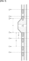
- Fig. 2 shows a vehicle interior configuration when a windshield is viewed from a driver's seat position in the driving-assisted vehicle.
- Fig. 3 shows driver-operated operation switches provided on a steering wheel of the driving-assisted vehicle. The overall system configuration will be described below based on Figs. 1-3 .
- the on-board sensors 1 have a camera 11, a radar 12, a GPS 13, and an on-board data communicator 14. Sensor information acquired by the on-board sensors 1 is output to the ADAS control unit 4.
- the camera 11 is a host vehicle surroundings recognition sensor that fulfills a function of acquiring information on host vehicle surroundings, such as a current lane, neighboring lanes, vehicles surrounding the host vehicle, and pedestrians around the host vehicle, from image data.
- the camera 11 combines a forward recognition camera, a rearward recognition camera, a rightward recognition camera, a leftward recognition camera, and the like, and is configured so as to have an Around View Monitor function.
- Objects in a host vehicle travel path lanes, objects outside the host vehicle travel path (roadway structures, preceding vehicles, trailing vehicles, oncoming vehicles, surrounding vehicles, pedestrians, bicycles, and motorcycles), the host vehicle travel path (roadway white lines, roadway boundaries, stop lines, and pedestrian crossings), traffic signs (speed limits), and the like are sensed by this camera 11.
- the GPS 13 includes a GNSS antenna and is a host vehicle position sensor that senses the position (latitude and longitude) of a stopped or traveling host vehicle through the use of satellite communication.
- GNSS is an abbreviation for “global navigation satellite system”
- GPS is an abbreviation for “Global Positioning System.”
- the "external data communicator 3" is, for instance, a data communicator provided in an infrastructure facility
- infrastructure communication can be carried out between the host vehicle and the infrastructure facility, and information required by the host vehicle can be acquired through requests. For instance, if there is information missing from map data saved in the map data storage unit 2 or information that has been changed from the map data, the missing or changed information can be supplemented. It is also possible to acquire traffic information such as information on traffic jams on a travel route of the host vehicle, or travel regulation information.
- the map data storage unit 2 is configured from on-board memory in which is stored so-called electronic map data, in which latitude/longitude and map information are associated.
- the map data stored in the map data storage unit 2 is high-accuracy map data with accuracy of a level that fundamentally allows recognition of lanes, with the exception of geographical areas for which there is no high-accuracy map data.
- high-accuracy map data has roadway information associated with geographic points, and the roadway information is defined by nodes and links that connect the nodes.
- the roadway information includes information that specifies roadways by the positions or regions of the roadways and information on roadway types of each roadway, lane widths of each roadway, and shapes of roadways.
- the roadway information is stored so that positions of intersections, entry directions of intersections, types of intersections, and other information relating to intersections are associated with each set of identifying information on roadway links.
- the roadway information is stored so that roadway types, lane widths, roadway shapes, whether or not straight driving is possible, advancement precedence relationships, whether or not passing is possible (whether or not neighboring lanes can be entered), speed limits, signs, and other information relating to roadways are associated with each set of identifying information on roadway links.
- the travel drive source controller 42 performs longitudinal control in which a drive command value is computed and output to a drive actuator 51 so that an actual vehicle speed of the host vehicle will reach the target vehicle speed.
- the brake controller 43 performs longitudinal control in which a braking command value is computed and output to the brake actuator 52 so that an actual braking deceleration of the host vehicle will reach the target braking deceleration.
- the steering wheel assist controller 44 exercises the lane-keeping function, in which steering control (lateral control) is performed and steering operation of the driver is assisted so that the host vehicle travels in a central section of the lane based on detection of lane markers on both sides of the lane by the forward recognition camera.
- This steering wheel assist controller 44 has, in addition to the lane-keeping function, a route travel assist function that includes as a condition that lane-keeping travel is being performed along a travel route generated in advance if the driver has set a destination in coordination with the navigation system 7.
- the HMI controller 46 generates a display command to a head-up display 61 and a meter display 62 so that working states of the vehicle speed/headway control function and the lane-keeping function, and changes in these working states, can be recognized visually. For instance, when "hands-off mode,” “hands-on mode,” “steering wheel operation mode,” and “steering wheel assist deactivation mode” are to be displayed, a display differentiating modes by color, an icon display, or a message display are utilized so that the driver can ascertain the working state at a glance. Moreover, an audio signal to a speaker 63 is generated when an announcement to the driver that appeals to the auditory sense becomes necessary, and an activation/stop command for an alarm 64 is generated when a warning to the driver that appeals to the auditory sense becomes necessary.
- "hands-off mode,” “hands-on mode,” and “steering wheel operation mode” are modes that differ only in being a mode in which the driver is allowed to take their hands off the steering wheel 23, a mode in which the driver is required to have their hands on the steering wheel 23, or a mode in which the driver is required to operate the steering wheel 23 with their hands, and are not modes in which the driving assist control is changed.
- “steering wheel assist deactivation mode” is a mode in which the lane-keeping function of the steering wheel assist controller 44 is deactivated, while the vehicle speed/headway control function of the accelerator/brake assist controller 41 is maintained.
- “steering wheel assist deactivation mode” is a mode in which steering wheel operation is transferred from the system to the driver.
- the navigation system 7 combines map data stored in the map data storage unit 2 with the GPS 13, which uses satellite communication, and, if a destination is set, generates a travel route from the current position of the host vehicle to the destination and navigates the host vehicle to the destination.
- a roadway map screen is displayed together with the travel route and a host vehicle icon on a navigation display 71.
- the navigation display 71 is disposed in an upper central position in the instrument panel 22, as shown in Fig. 2 , and has a function for setting the destination through touch operations or the like by the driver.
- the resume/accelerate switch 82 has a function for reactivation following deactivation at the set vehicle speed that was in effect before deactivation, a function for raising the set vehicle speed, and a function for resuming advancement after the host vehicle has stopped so as to follow a preceding vehicle.
- the set/coast switch 83 has a function for activation at a traveling vehicle speed and a function for lowering the set vehicle speed.
- the cancel switch 84 is a switch that cancels activation.
- the headway adjustment switch 85 is a switch that toggles between established headway settings.
- the lane-change assist switch 86 is a switch that issues an instruction for a lane change to be started when the system has confirmed the start of a lane change with the driver.
- the speed limit of the roadway being traveled is used as the set vehicle speed, and driving assist control by the ADAS control unit 4 is activated. If no speed limit has been detected for the roadway being traveled, or if speed limit assist has been turned off, the speed when the set/coast switch 83 was pressed will be used as the set vehicle speed, and driving assist control by the ADAS control unit 4 is activated.
- Driving assist control by the ADAS control unit 4 is deactivated when the cancel switch 84 is pressed, when the main switch 81 is pressed, or when the brake pedal is depressed (unless the host vehicle has been stopped by the vehicle speed/headway control function).
- the control information sensors 9 acquire information necessary to the execution of driving assist control by the ADAS control unit 4.
- the control information sensors 9 have a driver monitor camera 91, a touch sensor 92, a seating sensor 94, and a seatbelt buckle switch 95.
- the control information sensors have a torque sensor 93, a vehicle speed sensor 96, and an accelerator position sensor 97.
- the driver monitor camera 91 is set so that a camera lens faces the driver, and monitors the forward gaze of the driver (facial orientation and whether their eyes are open or closed).
- the touch sensor 92 (a capacitive sensor) is set in the steering wheel rim of the steering wheel 23, which is where the driver places their hands, and detects whether the driver has their hands on the steering wheel 23.
- the torque sensor 93 is installed in a steering force transmission unit of a steering mechanism, and detects whether a driver is adding steering torque to operate the steering wheel.
- the seating sensor 94 (a weight sensor) is set in a seat cushion 24 of a driver's seat, and detects whether the driver is seated.
- the seatbelt buckle switch 95 detects whether a seatbelt is locked.
- the vehicle speed sensor 96 detects the actual vehicle speed of the host vehicle.
- the accelerator position sensor 97 detects an accelerator depression when an accelerator operation has been performed by the driver.
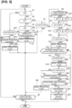
- a control block of the mode transition controller 47 is described below, based on Fig. 4 , which shows the mode transition controller 47 of the ADAS control unit 4.
- the mode transition controller 47 has a lane disappearance region detection unit 471, a position setting unit 472, a hands-on mode transition request unit 473, a steering wheel operation mode transition request unit 474, and a steering wheel assist deactivation mode transition unit 475.
- the mode transition controller 47 also has a hands-on mode transition request unit 476 and a hands-off mode transition unit 477.
- the position setting unit 472 acquires information on the lane disappearance start point and sets a first position (a position close to the host vehicle) and a second position (a position far from the host vehicle) between the host vehicle position and the lane disappearance start point.
- the hands-on mode transition request unit 473 requests a mode transition from "hands-off mode M1" to "hands-on mode M2."
- the setting of the first position differs depending on whether the roadway does not require the host vehicle to change lanes or the roadway does require a lane change.
- the request for the mode transition to "hands-on mode M2" is performed by changing display by color differentiation, icons, and message on the displays 61, 62 and by announcing "please hold the steering wheel.”
- the mode transition to "hands-on mode M2" is confirmed by monitoring a sensor signal from the touch sensor 92. Furthermore, regardless of the request for the mode transition to "hands-on mode M2,” if it is not possible to detect that the driver is holding the steering wheel within a prescribed length of time, the action (longitudinal control + lateral control) of the driving assist control is deactivated after the host vehicle has been decelerated and stopped.
- the steering wheel operation mode transition request unit 474 requests a mode transition from "hands-on mode M2" to "steering wheel operation mode M3."
- the origin point for positioning distance is caused to vary depending on whether or not a curve with a prescribed turning radius or less is present ahead of the lane disappearance region.
- the request for the mode transition to "steering wheel operation mode M3" is performed by changing the display of color differentiation, icons, and message on the displays 61, 62 and by announcing "please operate.”
- the mode transition to "steering wheel operation mode M3" is confirmed by monitoring a sensor signal from the torque sensor 93. Furthermore, regardless of the request for the mode transition to "steering wheel operation mode M3,” if it is not possible to detect steering wheel operation of the driver even after waiting a prescribed length of time, the action (longitudinal control + lateral control) of the driving assist control itself is deactivated after the host vehicle has been decelerated and stopped.
- the steering wheel assist deactivation mode transition unit 475 performs a mode transition from "steering wheel operation mode M3" to "steering wheel assist deactivation mode M4.” If a mode transition to "steering wheel assist deactivation mode M4" occurs, the display of color differentiation, icons, and messages on the displays 61, 62 is changed. The same condition of reaching the lane disappearance start point is applied as a condition for the mode transition to "steering wheel assist deactivation mode M4," regardless of the setting of the first position and the second position.
- the host vehicle With regard to the hands-on mode transition request unit 476, the host vehicle, with "steering wheel assist deactivation mode M4" selected, passes through the lane disappearance region to reach a lane disappearance end point, and lane recognition is resumed. Because starting lateral control to assist with steering wheel operation of the driver has become possible due to the resumption of lane recognition, a mode transition is made from “steering wheel assist deactivation mode M4" to "hands-on mode M2."
- the mode transition to "hands-on mode M2" is performed by starting lateral control and by changing display of color differentiation, icons, and messages on the displays 61, 62.
- the driver When “steering wheel assist deactivation mode M4" has been selected, the driver is holding the steering wheel to perform steering operations. Thus, the mode transition from "steering wheel assist deactivation mode M4" to "steering wheel operation mode M3" is omitted.
- the hands-off mode transition unit 477 When hands-off mode selection conditions are met during lane-keeping travel in "hands-on mode M2," the hands-off mode transition unit 477 performs a mode transition from “hands-on mode M2" to "hands-off mode M1.”
- the mode transition to "hands-off mode M1," in which hands can be off the steering wheel is performed by changing display of color differentiation, icons, and messages on the displays 61, 62.
- Multiple conditions are imposed as hands-off conditions for selecting "hands-off mode M1," for instance, "the vehicle is traveling at a vehicle speed at or below the speed limit," "the driver is holding the steering wheel 23,” “the accelerator pedal is not depressed,” and the like.
- Fig. 5 shows the flow of a control process for switching the driving assist modes that is executed by the mode transition controller 47 provided in the ADAS control unit 4. This process is started by the activation of driving assist control, and ends if driving assist control is deactivated.
- step S1 following the start or a determination in S6 that deactivation conditions for driving assist control have not been met, a determination is made as to whether or not the driving assist mode is "steering wheel assist deactivation mode M4." In the case of YES (the mode is "steering wheel assist deactivation mode M4"), the process proceeds to step S32, and in the case of NO (the mode is not "steering wheel assist deactivation mode M4"), the process proceeds to step S2.
- step S2 following a determination in S1 that the mode is not "steering wheel assist deactivation mode M4," a determination is made as to whether or not the driving assist mode is "hands-off mode M1.” In the case of YES (the mode is "hands-off mode M1"), the process proceeds to step S7, and in the case of NO (the mode is not "hands-off mode M1"), the process proceeds to step S3.
- step S3 following a determination in S2 that the mode is not "hands-off mode M1," a determination is made as to whether or not the driving assist mode is "hands-on mode M2." In the case of YES (the mode is "hands-on mode M2"), the process proceeds to step S4, and in the case of NO (the mode is not "hands-on mode M2"), the process proceeds to step S6.
- step S4 following a determination in S3 that the mode is "hands-on mode M2," a determination is made as to whether or not hands-off conditions for switching from "hands-on mode M2" to "hands-off mode M1" have been met. In the case of YES (hands-off conditions have been met), the process proceeds to step S5, and in the case of NO (hands-off conditions have not been met), the process proceeds to step S6.
- step S5 following a determination in S4 that the hands-off conditions have been met, a mode transition is performed from "hands-on mode M2" to "hands-off mode M1," and the process proceeds to step S6.
- step S6 following a mode transition to "hands-off mode M1" in S5, a mode transition to "hands-on mode M2" in S34, a mode transition to "steering wheel assist deactivation mode M4" in S21, or a determination of NO in S3, S7, or S32, a determination is made as to whether or not conditions for deactivating driving assist control have been met. In the case of YES (deactivation conditions have been met), the process proceeds to the end, and in the case of NO (deactivation conditions have not been met), the process returns to step S1.
- step S7 following a determination in step 2 that the mode is "hands-off mode M1," a determination is made as to whether or not a lane disappearance region S, in which a lane that continues from the current lane cannot be recognized, has been detected along an extension of the travel route of the host vehicle. In the case of YES (a lane disappearance region S was detected), the process proceeds to step S8, and in the case of NO (no lane disappearance region S was detected), the process proceeds to step S6.
- step S8 following a determination that a lane disappearance region S was detected in S7, a determination is made as to whether or not a lane change is necessary when it is assumed that the host vehicle will travel along the travel route toward the lane disappearance region S. In the case of YES (a lane change is not necessary), the process proceeds to step S9, and in the case of NO (a lane change is necessary), the process proceeds to step S10.
- step S9 following a determination in S8 that a lane change is not necessary, a position a first distance X1 from the lane disappearance start point Ps1 is set as the first position P1, and the process proceeds to step S11.
- step S10 following a determination in S8 that a lane change is necessary, a lane change start point Pe1 is set as the first position P1, and the process proceeds to step S11.
- the setting of the first position P1 differs depending on whether or not a lane change is necessary.
- step S11 following the setting of the first position P1 in S9 or S10, a determination is made as to whether or not there is a curve C with a turning radius at or below a prescribed value ahead of the lane disappearance region S. In the case of YES (there is no curve C), the process proceeds to step S12, and in the case of NO (there is a curve C), the process proceeds to step S13.
- step S12 following a determination in S11 that there is no curve C, a position a second distance X2, which is less than the first distance X1, from the lane disappearance start point Ps1 is set as the second position P2, and the process proceeds to step S14.
- step S13 following a determination in S11 that there is a curve C, a position the second distance X2, which is less than the first distance X1, from a curve start point Pc1 is set as the second position P2, and the process proceeds to step S14. That is, the setting of the second position P2 differs depending on whether or not there is a curve C.
- step S14 following the setting of the second position P2 in S12 or S13, a determination is made as to whether or not the host vehicle has reached the second position P1. In the case of YES (the first position P1 has been reached), the process proceeds to step S15, and in the case of NO (the first position P1 has not been reached), the determination of step S14 is repeated.
- step S15 following a determination in S14 that the first position P1 has been reached, a mode transition from "hands-off mode M1" to "hands-on mode M2" is requested, and the process proceeds to step S16.
- step S16 following the mode transition to "hands-on mode M2" in S15, a determination is made as to whether or not the driver has gripped the steering wheel 23 within a prescribed length of time since the request for the mode transition to "hands-on mode M2." In the case of YES (the steering wheel was gripped within the prescribed length of time), the process proceeds to step S17, and in the case of NO (the steering wheel was not gripped within the prescribed length of time), the process proceeds to step S23.
- step S17 following a determination in S16 that the steering wheel was gripped within the prescribed length of time, a determination is made as to whether or not the host vehicle has reached the second position P2. In the case of YES (the second position P2 was reached), the process proceeds to step S18, and in the case of NO (the second position P2 was not reached), the determination of step S17 is repeated.
- step S18 following a determination in S17 that the second position P2 was reached, a mode transition from "hands-on mode M2" to "steering wheel operation mode M3" is requested, and the process proceeds to step S19.
- step S19 following the mode transition to "steering wheel operation mode M3" in S18 or a determination in S22 that the prescribed length of time has not elapsed in M3, a determination is made as to whether or not the host vehicle has reached the lane disappearance start point Ps1. In the case of YES (the lane disappearance start point Ps1 was reached), the process proceeds to step S21, and in the case of NO (the lane disappearance start point Ps1 was not reached), the process proceeds to step S20.
- step S20 following a determination in S19 that the lane disappearance start point Ps1 was not reached, a determination is made as to whether or not the driver, holding the steering wheel 23, performed a steering wheel operation. In the case of YES (a steering wheel operation was performed), the process proceeds to step S21, and in the case of NO (a steering wheel operation was not performed), the process proceeds to S22.
- step S21 following a determination in S19 that the lane disappearance start point Ps1 was reached or a determination in S20 that a steering wheel operation was performed, a state transition from "steering wheel operation mode M3" to "steering wheel assist deactivation mode M4" is performed, and the process proceeds to step S6.
- step S22 following a determination in S20 that a steering wheel operation was not performed, a determination is made as to whether or not a prescribed length of time has elapsed in "steering wheel operation mode M3." In the case of YES (the prescribed length of time has elapsed in M3), the process proceeds to step S23, and in the case of NO (the prescribed length of time has not elapsed in M3), the process proceeds to step S19.
- step S23 following a determination in S16 that the steering wheel was not gripped within the prescribed length of time or a determination in S22 that the prescribed length of time has not elapsed in M3, the host vehicle is decelerated and stopped, and the process proceeds to step S24.
- "decelerating" is displayed on the displays 61, 62, and the host vehicle is decelerated to a stop.
- step S33 following a determination in S32 that the lane disappearance end point Ps2 was reached, a determination is made as to whether or not lane recognition by the forward recognition camera has been resumed. In the case of YES (lane recognition was resumed), the process proceeds to step S34, and in the case of NO (lane recognition was not resumed), the process proceeds to step S6.
- a driving-assisted vehicle includes a vehicle speed/headway control function and a lane-keeping function as driving assist functions to assist driving operations of a driver, that includes as a condition that a driver has their hands on a steering wheel, and that performs lane-keeping travel in a single lane.
- This driving-assisted vehicle by having as a condition that the driver has their hands on the steering wheel, consistently gives the driver agency in driving.
- the lane disappearance region S in which steering wheel assist by the system is to be deactivated, can be ascertained in advance in a scenario involving lane-keeping travel in "hands-off mode M1," in which the level of driving assistance is raised. If the lane disappearance region S is ascertained in advance, sequence control is performed in which mode transition points are decided, and the transitions "hands-off mode M1" ⁇ "steering wheel grip mode M2, M3" ⁇ "steering wheel assist deactivation mode M4" occur.
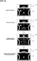
- the head-up display 61 and the meter display 62 have a steering wheel icon display unit, a speed limit display unit, a set vehicle speed display unit, a message display unit, a lane/host vehicle display unit, etc. Then, while "hands-off mode M1" is selected, the steering wheel icon display unit, for instance, displays in blue and displays an icon of the steering wheel alone, as shown in display D1 in Fig. 6 .
- the steering wheel icon display unit displays in white and displays an icon of the steering wheel and hands, as shown in display D4 in Fig. 6 .
- the driver can be notified of the transition in the driving assist mode through changes in what is displayed by the head-up display 61 and the meter display 62.
- the process proceeds in the order S1 ⁇ S2 ⁇ S7.
- S7 a determination is made as to whether or not a lane disappearance region S, in which no lane that continues from the current lane can be recognized, has been detected along an extension of the travel route of the host vehicle.
- a flow proceeding in the order S1 ⁇ S2 ⁇ S7 ⁇ S6 is repeated as long as no lane disappearance region S is detected.
- the process proceeds from S11 to S12, and in cases in which there is a curve C, the process proceeds from S11 to S13.
- a position the second distance X2, which is less than the first distance X1, from the lane disappearance start point Ps1 is set as the second position P2.
- step S13 a position the second distance X2, which is less than the first distance X1, from the curve start point Pc1 is set as the second position P2.
- S14 a determination is made as to whether or not the host vehicle has reached the first position P1, and the process proceeds to S15 if the first position P1 has been reached.
- S15 a mode transition from "hands-off mode M1" to "hands-on mode M2" is requested.
- S16 a determination is made as to whether or not the steering wheel has been gripped within a prescribed length of time. If the steering wheel has been gripped within the prescribed length of time, the process proceeds to S17, and if the steering wheel has not been gripped within the prescribed length of time, the process proceeds to S23.
- S17 a determination is made as to whether or not the host vehicle has reached the second position P2, and the process proceeds to S18 if the second position P2 has been reached.
- S18 a mode transition from "hands-on mode M2" to "steering wheel operation mode M3" is requested.
- S19 a determination is made as to whether or not the host vehicle has reached the lane disappearance start point Ps1. If it is determined in S19 that the lane disappearance start point Ps1 has been reached, the process proceeds to S21.
- S21 a mode transition is performed from "steering wheel operation mode M3" to "steering wheel assist deactivation mode M4,” and the process proceeds to S6.
- S20 a determination is made as to whether or not a steering wheel operation has been performed. If it is determined that a steering wheel operation has been performed, the process proceeds to S21. In S21, a mode transition is performed from "steering wheel operation mode M3" to "steering wheel assist deactivation mode M4," and the process proceeds to S6.
- S22 a determination is made as to whether a prescribed length of time has elapsed in M3. If it is determined that the prescribed length of time has not elapsed in "steering wheel operation mode M3," a flow proceeding in the order S19 ⁇ S20 ⁇ S22 is repeated. If the prescribed length of time has elapsed in a state in which the lane disappearance start point Ps1 has not been reached and no steering wheel operation has been performed, the process proceeds to S23. In S23, the host vehicle is decelerated and stopped, and in S24, driving assist control (longitudinal control + lateral control) is deactivated, and driving assist control ends.
- driving assist control Longitudinal control + lateral control
- S33 a determination is made as to whether or not lane recognition by the forward recognition camera has been resumed. Then, in cases in which lane recognition has been resumed, the process proceeds from S33 to S34.
- S34 a mode transition is performed from "steering wheel assist deactivation mode M4" to "hands-on mode M2," and the process proceeds to S6. Then, the process proceeds in the order S1 ⁇ S2 ⁇ S3 ⁇ S4. If it is determined in S4 that the hands-off conditions have been met, the process proceeds from S4 to S5, a mode transition is performed from "hands-on mode M2" to "hands-off mode M1" in S5, and the mode is restored to "hands-off mode M1.
- control for switching driving assist modes in lane-keeping travel toward a lane disappearance region S based on "hands-off mode M1" is divided below into four different travel scenarios for explanation, corresponding to the cases (a)-(d) above.
- a curve C and a toll plaza on a main road (lane disappearance region S), in which no lane that continues from the current lane can be recognized, will be considered to have been detected along an extension of the travel route of the host vehicle based on the high-accuracy map data during lane-keeping travel toward the curve C and the toll plaza in "hands-off mode M1."
- information on the curve start point Pc1 and a curve end point Pc2 is acquired if the curve C is detected, and information on the lane disappearance start point Ps1 and the lane disappearance end point Ps2 is acquired if the toll plaza is detected.
- the first position P1 and the second position P2, which have the curve start point Pc1 as an origin, are set between the host vehicle position and the lane disappearance start point Ps1.
- a branch road Y, a curve C, and a toll plaza on the branch road (lane disappearance region S), in which no lane that continues from the current lane can be recognized, will be considered to have been detected along an extension of the travel route of the host vehicle based on the high-accuracy map data during lane-keeping travel toward the curve C and the toll plaza on the branch road in "hands-off mode M1."
- information on the lane change start point Pe1 and the lane change end point Pe2 according to the route travel assist function are acquired if the branch road Y is detected.
- Information on the curve start point Pc1 and the curve end point Pc2 is acquired if the curve C is detected.
- a mode transition from "hands-off mode M1" to "hands-on mode M2" is requested, and a lane change by the route travel assist function is started.
- the host vehicle enters the branch road Y, changes lanes, and proceeds to the lane change end point Pe2, whereby the lane change ends.
- a mode transition from "hands-on mode M2" to "steering wheel operation mode M3" is requested if the host vehicle reaches the second position P2.
- the driving assist method and driving assist device of the first embodiment exhibit the effects enumerated below.
- the driving assist method and the driving assist method of the present disclosure have been described above based on the first embodiment.
- the specific configuration is not limited to the first embodiment; design changes, additions, etc., can be made as long as these do not deviate from the scope of the invention as in the claims.
- the mode transition controller 47 was presented that performed the mode transitions "hands-off mode M1" --+ “hands-on mode M2" ⁇ "steering wheel operation mode M3" ⁇ “steering wheel assist deactivation mode M4.”
- the mode transition controller can also have at least one mode in which it is possible to confirm that the driver is holding the steering wheel between "hands-off mode” and "steering wheel assist deactivation mode.”
- an example can also be provided in which the mode transitions "hands-off mode” ⁇ "steering wheel grip mode” ⁇ "steering wheel assist deactivation mode” are performed.
- the driving assist method and the driving assist device of the present disclosure were employed in a driving-assisted vehicle having an onboard advanced driver assist system (ADAS) that assists driving operations of the driver.
- ADAS advanced driver assist system
- the driving assist method and the driving assist device of the present disclosure can be applied to a self-driving vehicle that performs operation assistance control for driving, braking, and steering angle in accordance with a target travel path and that travels by autonomous driving (AD) when an autonomous driving mode is selected.
- AD autonomous driving
Landscapes
- Engineering & Computer Science (AREA)
- Automation & Control Theory (AREA)
- Transportation (AREA)
- Mechanical Engineering (AREA)
- Human Computer Interaction (AREA)
- Physics & Mathematics (AREA)
- General Physics & Mathematics (AREA)
- Traffic Control Systems (AREA)
- Control Of Driving Devices And Active Controlling Of Vehicle (AREA)
- Steering Control In Accordance With Driving Conditions (AREA)
Claims (16)
- Fahrassistenzverfahren, das eine Fahrzeuggeschwindigkeits-/Abstandsregelungsfunktion und eine Spurhaltefunktion als Fahrassistenzfunktionen enthält, um Fahrtätigkeiten durch einen Fahrer zu unterstützen, und das eine Modusübergangssteuerung zum Übergang zwischen Fahrassistenzmodi verwendet, dadurch gekennzeichnet, dass:das Fahrassistenzverfahren als Fahrassistenzmodi einen Hands-Off-Modus (M1), in dem der Fahrer seine Hände vom Lenkrad nehmen darf, einen Hands-On-Modus (M2), der als Bedingung aufweist, dass der Fahrer seine Hände am Lenkrad hat, einen Lenkradbedienungsmodus (M3), der den Fahrer dazu anregt, Lenkradbedienungen durchzuführen, und einen Lenkradassistenz-Deaktivierungsmodus (M4) aufweist, in dem die Spurhaltefunktion deaktiviert ist;Erfassen von Informationen, dass ein Spurwegfallbereich (S), in dem keine Spur erkannt werden kann, die sich von einer aktuellen Spur fortsetzt, entlang einer Verlängerung einer Fahrtroute eines Host-Fahrzeugs während der Spurhaltefahrt existiert, in der der Hands-Off-Modus ausgewählt wurde;Erfassen von Informationen über einen Spurwegfallstartpunkt (Ps1), wenn der Spurwegfallbereich im Voraus bekannt ist, und Einstellen einer ersten Position (P1) und einer zweiten Position (P2) zwischen einer Position des Host-Fahrzeugs und dem Spurwegfallstartpunkt;Anfordern eines Modusübergangs vom Hands-Off-Modus zum Hands-On-Modus, wenn das Host-Fahrzeug die erste Position erreicht;Anfordern eines Modusübergangs vom Hands-On-Modus zum Lenkradbedienungsmodus, wenn das Host-Fahrzeug die zweite Position erreicht; undDurchführen eines Modusübergangs vom Lenkradbedienungsmodus zum Lenkradassistenz-Deaktivierungsmodus, bevor das Host-Fahrzeug den Spurwegfallstartpunkt erreicht, wenn bestätigt wurde, dass der Fahrer das Lenkrad hält.
- Fahrassistenzverfahren nach Anspruch 1, wobei:
in Fällen, in denen es nicht möglich ist zu bestätigen, dass der Fahrer innerhalb einer vorgeschriebenen Zeitspanne die Hände am Lenkrad hat, nachdem der Modusübergang zum Hands-On-Modus angefordert wurde, und in Fällen, in denen eine vorgeschriebene Zeitspanne verstrichen ist, in denen es nicht möglich war zu bestätigen, dass der Fahrer das Lenkrad bedient, nachdem der Modusübergang zum Lenkradbedienungsmodus angefordert wurde, das Host-Fahrzeug abgebremst und angehalten wird, und dann die Fahrzeuggeschwindigkeits-/Abstandsregelungsfunktion und die Spurhaltefunktion, die Fahrassistenzfunktionen sind, deaktiviert werden. - Verfahren zur Fahrunterstützung nach Anspruch 1 oder 2, wobei:Überwachen eines Berührungssensors dahingehend, ob der Fahrer seine Hände am Lenkrad hat oder nicht, nachdem der Modusübergang vom Hands-Off-Modus zum Hands-On-Modus angefordert wurde; undÜberwachen des Drehmomentsensors, der überwacht, ob der Fahrer eine Lenkradbedienung durchgeführt hat oder nicht, nachdem der Modusübergang vom Hands-On-Modus zum Lenkradbedienungsmodus angefordert wurde.
- Fahrassistenzverfahren nach Anspruch 1, wobei:
nach der Anforderung des Modusübergangs vom Hands-On-Modus zum Lenkradbedienungsmodus der Modusübergang vom Lenkradbedienungsmodus zum Lenkradassistenz-Deaktivierungsmodus durchgeführt wird, wenn eine Lenkradbedienung erkannt wird, bevor das Host-Fahrzeug den Spurwegfallstartpunkt erreicht. - Fahrassistenzverfahren nach Anspruch 1 oder 4, wobei:Bestimmen, ob ein Spurwechsel notwendig oder unnötig ist und ob eine Kurve vorhanden ist oder nicht, wenn die Informationen über den Spurwegfallstartpunkt erfasst werden; unddie erste Position und die zweite Position gemäß den Ergebnissen der Bestimmung eingestellt werden, ob der Spurwechsel notwendig oder unnötig ist und ob die Kurve vorhanden oder nicht vorhanden ist.
- Fahrassistenzverfahren nach Anspruch 5, wobei:
in Fällen, in denen ein Spurhalte-Fahrweg, der den Hands-Off-Modus verwendet, eine Fahrbahn ist, die es nicht erfordert, dass das Host-Fahrzeug die Spur wechselt, die erste Position auf eine Position eingestellt wird, die einen ersten Abstand vom Spurwegfallstartpunkt aufweist, und die zweite Position auf eine Position eingestellt wird, die einen zweiten Abstand vom Spurwegfallstartpunkt aufweist, der geringer als der erste Abstand ist. - Fahrassistenzverfahren nach Anspruch 5 oder 6, wobei:das Fahrassistenzverfahren eine Routenfahrt-Assistenzfunktion aufweist, die in Fällen, in denen der Fahrer ein Ziel festgelegt hat, Spurwechsel unter Verwendung der Lenkung unterstützt, wenn ein für die Fahrt entlang der Fahrtroute notwendiger Spurwechsel-Startpunkt erreicht und eine Absicht bestätigt wird, einen Spurwechsel durch Fahrerbetätigung durchzuführen; und in Fällen, in denen der Spurhalte-Fahrweg unter Verwendung des Hands-Off-Modus eine Fahrbahn ist, die es erfordert, dass das Host-Fahrzeug die Spur wechselt, die erste Position auf den Spurwechsel-Startpunkt gesetzt wird, unddie zweite Position wird auf eine Position gesetzt wird, die durch einen vorgeschriebenen Abstand vom Spurwechsel-Startpunkt getrennt ist.
- Fahrassistenzverfahren nach einem der Ansprüche 5 bis 7, wobei:
in Fällen, in denen eine Kurve mit einem Kurvenradius bei oder unter einem vorgeschriebenen Wert vor dem Spurwegfallbereich liegt, wenn die erste Position oder die zweite Position eingestellt ist, der Ursprung für das Einstellen der Position vom Spurwegfallstartpunkt zum Kurvenstartpunkt der Kurve geändert wird. - Fahrassistenzverfahren nach Anspruch 8, wobei:
in Fällen, in denen eine Kurve mit einem Kurvenradius bei oder unter dem vorgeschriebenen Wert vor dem Spurwegfallbereich liegt, eine Soll-Querbeschleunigung für die kurvenkoordinierte Verzögerung im Lenkradbedienungsmodus niedriger gemacht wird als die Werte der Soll-Querbeschleunigung für die kurvenkoordinierte Verzögerung im Hands-on-Modus, im Hands-off-Modus und im Lenkradassistenz-Deaktivierungsmodus. - Fahrassistenzverfahren nach einem der Ansprüche 1 bis 9, wobei:wenn das Host-Fahrzeug den Spurwegfallbereich durchfährt, um den Spurwegfallendpunkt zu erreichen, wobei der Lenkradassistenz-Deaktivierungsmodus ausgewählt ist und die Spurerkennung wieder aufgenommen wird, der Modusübergang vom Lenkradassistenz-Deaktivierungsmodus zum Hands-On-Modus durchgeführt wird; undwenn Hands-Off-Bedingungen während der Spurhaltefahrt im Hands-On-Modus erfüllt werden, der Modusübergang vom Hands-On-Modus zum Hands-Off-Modus durchgeführt wird.
- Fahrassistenzverfahren nach einem der Ansprüche 1 bis 10, wobei:
der Spurwegfallbereich, eine Ausfahrtstelle ist, für die die Kartendaten keine Spurinformationen enthalten. - Fahrassistenzverfahren nach einem der Ansprüche 1 bis 10, wobei:
der Spurwegfallbereich, eine Mautstelle ist, für die die Kartendaten die Informationen enthalten, dass es keine Spuren gibt. - Fahrassistenzverfahren nach einem der Ansprüche 1 bis 10, wobei:
der Spurwegfallbereich, ein spurloses Segment ist, für das die Kartendaten die Informationen enthalten, dass es keine Spuren gibt. - Fahrassistenzverfahren nach einem der Ansprüche 1 bis 10, wobei:
der Spurwegfallbereich, eine Einmündungsstelle ist, für die die Kartendaten Informationen enthalten, dass die aktuelle Spur aufgrund der Einmündung wegfallen wird. - Fahrassistenzverfahren nach einem der Ansprüche 1 bis 10, wobei:
der Spurwegfallbereich, eine Spurreduzierungsstelle ist, für die Kartendaten Informationen darüber enthalten, dass die aktuelle Spur aufgrund einer Spurreduzierung wegfallen wird. - Fahrassistenzvorrichtung, die eine Fahrzeuggeschwindigkeits-/Abstandsregelungsfunktion und eine Spurhaltefunktion als Fahrassistenzfunktionen enthält, um Fahrtätigkeiten durch einen Fahrer zu unterstützen, und die mit einer Modusübergangssteuerung zum Übergang eines Fahrassistenzmodus versehen ist, dadurch gekennzeichnet, dass:das Fahrassistenzverfahren als Fahrassistenzmodi einen Hands-Off-Modus (M1), in dem der Fahrer seine Hände vom Lenkrad nehmen darf, einen Hands-On-Modus (M2), der als Bedingung beinhaltet, dass der Fahrer seine Hände am Lenkrad hat, einen Lenkradbedienungsmodus (M3), der den Fahrer ermutigt,Lenkradbedienungen durchzuführen, und einen Lenkradassistenz-Deaktivierungsmodus (M4) aufweist, in dem die Spurhaltefunktion deaktiviert ist;die Modusübergangssteuerung aufweist:eine Spurwegfallbereich-Erfassungseinheit, die Informationen darüber erfasst, dass ein Spurwegfallbereich (S), in dem keine Spur erkannt werden kann, die sich von einer aktuellen Spur fortsetzt, entlang einer Verlängerung einer Fahrtroute eines Host-Fahrzeugs während der Spurhaltefahrt existiert, in der der Hands-Off-Modus ausgewählt worden ist,eine Positionseinstellungseinheit, die Informationen über einen Spurwegfallstartpunkt (Ps1) erfasst, wenn der Spurwegfallbereich im Voraus bekannt ist, und die eine erste Position (P1) und eine zweite Position (P2) zwischen einer Position des Host-Fahrzeugs und dem Spurwegfallstartpunkt einstellt,eine Hands-On-Modus-Übergangsanforderungseinheit, die einen Modusübergang vom Hands-Off-Modus zum Hands-On-Modus anfordert, wenn das Host-Fahrzeug die erste Position erreicht,eine Lenkradbedienungsmodus-Übergangsanforderungseinheit, die einen Modusübergang vom Hands-On-Modus zum Lenkradbedienungsmodus anfordert, wenn das Host-Fahrzeug die zweite Position erreicht, undeine Lenkradassistenz-Deaktivierungsmodus-Übergangseinheit, die einen Modusübergang vom Lenkradbedienungsmodus zum Lenkradassistenz-Deaktivierungsmodus durchführt, bevor das Host-Fahrzeug den Spurwegfallstartpunkt erreicht, wenn bestätigt worden ist, dass der Fahrer das Lenkrad gehalten hat.
Priority Applications (1)
| Application Number | Priority Date | Filing Date | Title |
|---|---|---|---|
| EP23208267.7A EP4336475A1 (de) | 2019-05-15 | 2019-05-15 | Fahrassistenzverfahren und fahrassistenzvorrichtung |
Applications Claiming Priority (1)
| Application Number | Priority Date | Filing Date | Title |
|---|---|---|---|
| PCT/JP2019/019398 WO2020230308A1 (ja) | 2019-05-15 | 2019-05-15 | 運転支援方法及び運転支援装置 |
Related Child Applications (2)
| Application Number | Title | Priority Date | Filing Date |
|---|---|---|---|
| EP23208267.7A Division-Into EP4336475A1 (de) | 2019-05-15 | 2019-05-15 | Fahrassistenzverfahren und fahrassistenzvorrichtung |
| EP23208267.7A Division EP4336475A1 (de) | 2019-05-15 | 2019-05-15 | Fahrassistenzverfahren und fahrassistenzvorrichtung |
Publications (3)
| Publication Number | Publication Date |
|---|---|
| EP3971859A1 EP3971859A1 (de) | 2022-03-23 |
| EP3971859A4 EP3971859A4 (de) | 2022-09-14 |
| EP3971859B1 true EP3971859B1 (de) | 2023-12-13 |
Family
ID=73289554
Family Applications (2)
| Application Number | Title | Priority Date | Filing Date |
|---|---|---|---|
| EP23208267.7A Pending EP4336475A1 (de) | 2019-05-15 | 2019-05-15 | Fahrassistenzverfahren und fahrassistenzvorrichtung |
| EP19928311.0A Active EP3971859B1 (de) | 2019-05-15 | 2019-05-15 | Fahrassistenzverfahren und fahrassistenzvorrichtung |
Family Applications Before (1)
| Application Number | Title | Priority Date | Filing Date |
|---|---|---|---|
| EP23208267.7A Pending EP4336475A1 (de) | 2019-05-15 | 2019-05-15 | Fahrassistenzverfahren und fahrassistenzvorrichtung |
Country Status (6)
| Country | Link |
|---|---|
| US (1) | US11492015B2 (de) |
| EP (2) | EP4336475A1 (de) |
| JP (1) | JP7124963B2 (de) |
| CN (1) | CN113785342B (de) |
| RU (1) | RU2767830C1 (de) |
| WO (1) | WO2020230308A1 (de) |
Families Citing this family (7)
| Publication number | Priority date | Publication date | Assignee | Title |
|---|---|---|---|---|
| DE102018216364B4 (de) * | 2018-09-25 | 2020-07-09 | Volkswagen Aktiengesellschaft | Verfahren und Vorrichtung zum Unterstützen eines Spurwechselvorgangs für ein Fahrzeug |
| US11884291B2 (en) * | 2020-08-03 | 2024-01-30 | Waymo Llc | Assigning vehicles for transportation services |
| DE112020006785B4 (de) * | 2020-12-10 | 2023-11-30 | Honda Motor Co., Ltd. | Fahrzeugsteuerungsvorrichtung und fahrzeugsteuerungsverfahren |
| EP4052983B1 (de) * | 2021-03-04 | 2023-08-16 | Volvo Car Corporation | Verfahren zum übergang eines antriebsmodus eines fahrzeugs, antriebssteuerungssystem für ein fahrzeug und fahrzeug |
| WO2023032123A1 (ja) * | 2021-09-02 | 2023-03-09 | 本田技研工業株式会社 | 車両制御装置、車両制御方法、およびプログラム |
| US20230127515A1 (en) * | 2021-10-27 | 2023-04-27 | Ford Global Technologies, Llc | Methods and systems to control driver assist systems |
| CN114261403B (zh) * | 2022-03-03 | 2022-06-17 | 宁波均联智行科技股份有限公司 | 退出自动驾驶时的方向盘信息预警方法及系统 |
Family Cites Families (18)
| Publication number | Priority date | Publication date | Assignee | Title |
|---|---|---|---|---|
| JP3225806B2 (ja) | 1995-09-22 | 2001-11-05 | 三菱自動車工業株式会社 | 自動運転装置 |
| EP2119617A1 (de) * | 2008-05-12 | 2009-11-18 | IVECO S.p.A. | Fahrzeugfahrhilfesystem zur Unterstützung beim Wechseln der Fahrspur |
| JP5167051B2 (ja) * | 2008-09-30 | 2013-03-21 | 富士重工業株式会社 | 車両の運転支援装置 |
| DE102011077592A1 (de) | 2010-12-30 | 2012-07-19 | Hochschule für Technik und Wirtschaft Dresden | Verfahren und Anordnung zur Fahrzeugführung, mittels eines Fahrzeugführungssystems |
| JP5281664B2 (ja) * | 2011-02-23 | 2013-09-04 | クラリオン株式会社 | 車線逸脱警報装置および車線逸脱警報システム |
| CN103703497B (zh) * | 2011-07-26 | 2016-08-31 | 丰田自动车株式会社 | 车辆确定系统及车辆确定装置 |
| US9031729B2 (en) * | 2012-11-29 | 2015-05-12 | Volkswagen Ag | Method and system for controlling a vehicle |
| DE102015004550A1 (de) * | 2015-04-08 | 2016-10-13 | Audi Ag | Verfahren zum Betreiben eines Kraftfahrzeugs und Kraftfahrzeug |
| FR3038280B1 (fr) | 2015-07-03 | 2019-05-10 | Psa Automobiles Sa. | Dispositif et procede d’aide a la conduite |
| JP6604240B2 (ja) * | 2016-03-08 | 2019-11-13 | アイシン・エィ・ダブリュ株式会社 | 自動運転支援装置及びコンピュータプログラム |
| JP2017207885A (ja) | 2016-05-18 | 2017-11-24 | 本田技研工業株式会社 | 車両制御システム、車両制御方法、および車両制御プログラム |
| JP6495971B2 (ja) * | 2017-06-02 | 2019-04-03 | 本田技研工業株式会社 | 車両制御システム、車両制御方法、および車両制御プログラム |
| CN110730740B (zh) * | 2017-06-02 | 2022-11-22 | 本田技研工业株式会社 | 车辆控制系统、车辆控制方法及存储介质 |
| JP7074432B2 (ja) | 2017-06-26 | 2022-05-24 | 本田技研工業株式会社 | 車両制御システム、車両制御方法、および車両制御プログラム |
| JP6976089B2 (ja) * | 2017-06-29 | 2021-12-08 | 株式会社デンソーテン | 運転支援装置および運転支援方法 |
| CN108327717B (zh) * | 2018-02-06 | 2019-07-02 | 合肥工业大学 | 一种人机共驾的车道偏离辅助系统及其车道偏离辅助方法 |
| JP7055759B2 (ja) * | 2019-01-24 | 2022-04-18 | 本田技研工業株式会社 | 車両制御装置 |
| JP7307550B2 (ja) * | 2019-02-15 | 2023-07-12 | 株式会社Subaru | 車両の運転制御システム |
-
2019
- 2019-05-15 RU RU2021134012A patent/RU2767830C1/ru active
- 2019-05-15 US US17/605,592 patent/US11492015B2/en active Active
- 2019-05-15 CN CN201980096112.2A patent/CN113785342B/zh active Active
- 2019-05-15 JP JP2021519218A patent/JP7124963B2/ja active Active
- 2019-05-15 EP EP23208267.7A patent/EP4336475A1/de active Pending
- 2019-05-15 WO PCT/JP2019/019398 patent/WO2020230308A1/ja unknown
- 2019-05-15 EP EP19928311.0A patent/EP3971859B1/de active Active
Also Published As
| Publication number | Publication date |
|---|---|
| US20220266869A1 (en) | 2022-08-25 |
| WO2020230308A1 (ja) | 2020-11-19 |
| RU2767830C1 (ru) | 2022-03-22 |
| CN113785342B (zh) | 2024-03-12 |
| EP3971859A1 (de) | 2022-03-23 |
| JPWO2020230308A1 (de) | 2020-11-19 |
| JP7124963B2 (ja) | 2022-08-24 |
| US11492015B2 (en) | 2022-11-08 |
| EP3971859A4 (de) | 2022-09-14 |
| EP4336475A1 (de) | 2024-03-13 |
| CN113785342A (zh) | 2021-12-10 |
Similar Documents
| Publication | Publication Date | Title |
|---|---|---|
| EP3971859B1 (de) | Fahrassistenzverfahren und fahrassistenzvorrichtung | |
| EP3971867B1 (de) | Fahrassistenzverfahren und fahrassistenzvorrichtung | |
| WO2018105058A1 (ja) | 車両制御装置 | |
| US20220234607A1 (en) | Driving Assistance Method and Driving Assistance System | |
| JP7022680B2 (ja) | 車両制御装置 | |
| WO2020230303A1 (ja) | 車両の走行制御方法及び走行制御装置 | |
| WO2018168322A1 (ja) | 運転支援制御装置 | |
| WO2020003366A1 (ja) | 運転支援方法及び運転支援装置 | |
| JP7268433B2 (ja) | 車両用制御装置 | |
| JP2020104634A (ja) | 車両制御装置 | |
| JP7215596B2 (ja) | 運転制御方法及び運転制御装置 | |
| EP4074567A1 (de) | Fahrsteuerungsverfahren und fahrsteuerungsvorrichtung | |
| JP2018154218A (ja) | 運転支援制御装置 | |
| JP2011221757A (ja) | 運転支援装置 | |
| JP2012212271A (ja) | 運転支援装置 | |
| JP2018134971A (ja) | 車両制御装置 | |
| JP2018154217A (ja) | 運転支援制御装置 | |
| RU2798793C2 (ru) | Способ и устройство помощи при вождении | |
| JP7211552B2 (ja) | 車両の走行制御方法及び走行制御装置 | |
| WO2023002543A1 (ja) | 車両の運転モード切り替え制御方法及び運転モード切り替え制御装置 | |
| RU2792474C1 (ru) | Способ управления вождением и устройство управления вождением | |
| WO2023042272A1 (ja) | 運転制御方法及び運転制御装置 | |
| WO2024013997A1 (ja) | 車両の運転支援方法及び運転支援装置 | |
| WO2024013996A1 (ja) | 車両の運転支援方法及び運転支援装置 | |
| WO2024013874A1 (ja) | 車両の運転支援方法及び運転支援装置 |
Legal Events
| Date | Code | Title | Description |
|---|---|---|---|
| STAA | Information on the status of an ep patent application or granted ep patent |
Free format text: STATUS: THE INTERNATIONAL PUBLICATION HAS BEEN MADE |
|
| PUAI | Public reference made under article 153(3) epc to a published international application that has entered the european phase |
Free format text: ORIGINAL CODE: 0009012 |
|
| STAA | Information on the status of an ep patent application or granted ep patent |
Free format text: STATUS: REQUEST FOR EXAMINATION WAS MADE |
|
| 17P | Request for examination filed |
Effective date: 20211208 |
|
| AK | Designated contracting states |
Kind code of ref document: A1 Designated state(s): AL AT BE BG CH CY CZ DE DK EE ES FI FR GB GR HR HU IE IS IT LI LT LU LV MC MK MT NL NO PL PT RO RS SE SI SK SM TR |
|
| DAV | Request for validation of the european patent (deleted) | ||
| DAX | Request for extension of the european patent (deleted) | ||
| A4 | Supplementary search report drawn up and despatched |
Effective date: 20220811 |
|
| RIC1 | Information provided on ipc code assigned before grant |
Ipc: B60W 30/18 20120101ALI20220805BHEP Ipc: B60W 60/00 20200101ALI20220805BHEP Ipc: G08G 1/16 20060101AFI20220805BHEP |
|
| GRAP | Despatch of communication of intention to grant a patent |
Free format text: ORIGINAL CODE: EPIDOSNIGR1 |
|
| STAA | Information on the status of an ep patent application or granted ep patent |
Free format text: STATUS: GRANT OF PATENT IS INTENDED |
|
| INTG | Intention to grant announced |
Effective date: 20230704 |
|
| GRAS | Grant fee paid |
Free format text: ORIGINAL CODE: EPIDOSNIGR3 |
|
| GRAA | (expected) grant |
Free format text: ORIGINAL CODE: 0009210 |
|
| STAA | Information on the status of an ep patent application or granted ep patent |
Free format text: STATUS: THE PATENT HAS BEEN GRANTED |
|
| AK | Designated contracting states |
Kind code of ref document: B1 Designated state(s): AL AT BE BG CH CY CZ DE DK EE ES FI FR GB GR HR HU IE IS IT LI LT LU LV MC MK MT NL NO PL PT RO RS SE SI SK SM TR |
|
| REG | Reference to a national code |
Ref country code: GB Ref legal event code: FG4D |
|
| REG | Reference to a national code |
Ref country code: CH Ref legal event code: EP |
|
| REG | Reference to a national code |
Ref country code: DE Ref legal event code: R096 Ref document number: 602019043428 Country of ref document: DE |
|
| REG | Reference to a national code |
Ref country code: IE Ref legal event code: FG4D |
|
| PG25 | Lapsed in a contracting state [announced via postgrant information from national office to epo] |
Ref country code: GR Free format text: LAPSE BECAUSE OF FAILURE TO SUBMIT A TRANSLATION OF THE DESCRIPTION OR TO PAY THE FEE WITHIN THE PRESCRIBED TIME-LIMIT Effective date: 20240314 |
|
| REG | Reference to a national code |
Ref country code: LT Ref legal event code: MG9D |
|
| PG25 | Lapsed in a contracting state [announced via postgrant information from national office to epo] |
Ref country code: LT Free format text: LAPSE BECAUSE OF FAILURE TO SUBMIT A TRANSLATION OF THE DESCRIPTION OR TO PAY THE FEE WITHIN THE PRESCRIBED TIME-LIMIT Effective date: 20231213 |
|
| REG | Reference to a national code |
Ref country code: NL Ref legal event code: MP Effective date: 20231213 |
|
| PG25 | Lapsed in a contracting state [announced via postgrant information from national office to epo] |
Ref country code: ES Free format text: LAPSE BECAUSE OF FAILURE TO SUBMIT A TRANSLATION OF THE DESCRIPTION OR TO PAY THE FEE WITHIN THE PRESCRIBED TIME-LIMIT Effective date: 20231213 |
|
| PG25 | Lapsed in a contracting state [announced via postgrant information from national office to epo] |
Ref country code: LT Free format text: LAPSE BECAUSE OF FAILURE TO SUBMIT A TRANSLATION OF THE DESCRIPTION OR TO PAY THE FEE WITHIN THE PRESCRIBED TIME-LIMIT Effective date: 20231213 Ref country code: GR Free format text: LAPSE BECAUSE OF FAILURE TO SUBMIT A TRANSLATION OF THE DESCRIPTION OR TO PAY THE FEE WITHIN THE PRESCRIBED TIME-LIMIT Effective date: 20240314 Ref country code: ES Free format text: LAPSE BECAUSE OF FAILURE TO SUBMIT A TRANSLATION OF THE DESCRIPTION OR TO PAY THE FEE WITHIN THE PRESCRIBED TIME-LIMIT Effective date: 20231213 Ref country code: BG Free format text: LAPSE BECAUSE OF FAILURE TO SUBMIT A TRANSLATION OF THE DESCRIPTION OR TO PAY THE FEE WITHIN THE PRESCRIBED TIME-LIMIT Effective date: 20240313 |