EP3967482B1 - Verfahren zur herstellung von einer gummi-rolle - Google Patents
Verfahren zur herstellung von einer gummi-rolle Download PDFInfo
- Publication number
- EP3967482B1 EP3967482B1 EP21195850.9A EP21195850A EP3967482B1 EP 3967482 B1 EP3967482 B1 EP 3967482B1 EP 21195850 A EP21195850 A EP 21195850A EP 3967482 B1 EP3967482 B1 EP 3967482B1
- Authority
- EP
- European Patent Office
- Prior art keywords
- roll
- gum
- skid
- gum roll
- strip stock
- Prior art date
- Legal status (The legal status is an assumption and is not a legal conclusion. Google has not performed a legal analysis and makes no representation as to the accuracy of the status listed.)
- Active
Links
Images


Classifications
-
- B—PERFORMING OPERATIONS; TRANSPORTING
- B65—CONVEYING; PACKING; STORING; HANDLING THIN OR FILAMENTARY MATERIAL
- B65D—CONTAINERS FOR STORAGE OR TRANSPORT OF ARTICLES OR MATERIALS, e.g. BAGS, BARRELS, BOTTLES, BOXES, CANS, CARTONS, CRATES, DRUMS, JARS, TANKS, HOPPERS, FORWARDING CONTAINERS; ACCESSORIES, CLOSURES, OR FITTINGS THEREFOR; PACKAGING ELEMENTS; PACKAGES
- B65D85/00—Containers, packaging elements or packages, specially adapted for particular articles or materials
- B65D85/67—Containers, packaging elements or packages, specially adapted for particular articles or materials for web or tape-like material
- B65D85/671—Containers, packaging elements or packages, specially adapted for particular articles or materials for web or tape-like material wound in flat spiral form
- B65D85/672—Containers, packaging elements or packages, specially adapted for particular articles or materials for web or tape-like material wound in flat spiral form on cores
-
- B—PERFORMING OPERATIONS; TRANSPORTING
- B29—WORKING OF PLASTICS; WORKING OF SUBSTANCES IN A PLASTIC STATE IN GENERAL
- B29D—PRODUCING PARTICULAR ARTICLES FROM PLASTICS OR FROM SUBSTANCES IN A PLASTIC STATE
- B29D30/00—Producing pneumatic or solid tyres or parts thereof
- B29D30/0016—Handling tyres or parts thereof, e.g. supplying, storing, conveying
-
- B—PERFORMING OPERATIONS; TRANSPORTING
- B65—CONVEYING; PACKING; STORING; HANDLING THIN OR FILAMENTARY MATERIAL
- B65B—MACHINES, APPARATUS OR DEVICES FOR, OR METHODS OF, PACKAGING ARTICLES OR MATERIALS; UNPACKING
- B65B11/00—Wrapping, e.g. partially or wholly enclosing, articles or quantities of material, in strips, sheets or blanks, of flexible material
- B65B11/04—Wrapping, e.g. partially or wholly enclosing, articles or quantities of material, in strips, sheets or blanks, of flexible material the articles being rotated
-
- B—PERFORMING OPERATIONS; TRANSPORTING
- B65—CONVEYING; PACKING; STORING; HANDLING THIN OR FILAMENTARY MATERIAL
- B65B—MACHINES, APPARATUS OR DEVICES FOR, OR METHODS OF, PACKAGING ARTICLES OR MATERIALS; UNPACKING
- B65B63/00—Auxiliary devices, not otherwise provided for, for operating on articles or materials to be packaged
- B65B63/04—Auxiliary devices, not otherwise provided for, for operating on articles or materials to be packaged for folding or winding articles, e.g. gloves or stockings
-
- B—PERFORMING OPERATIONS; TRANSPORTING
- B65—CONVEYING; PACKING; STORING; HANDLING THIN OR FILAMENTARY MATERIAL
- B65D—CONTAINERS FOR STORAGE OR TRANSPORT OF ARTICLES OR MATERIALS, e.g. BAGS, BARRELS, BOTTLES, BOXES, CANS, CARTONS, CRATES, DRUMS, JARS, TANKS, HOPPERS, FORWARDING CONTAINERS; ACCESSORIES, CLOSURES, OR FITTINGS THEREFOR; PACKAGING ELEMENTS; PACKAGES
- B65D71/00—Bundles of articles held together by packaging elements for convenience of storage or transport, e.g. portable segregating carrier for plural receptacles such as beer cans or pop bottles; Bales of material
- B65D71/0088—Palletisable loads, i.e. loads intended to be transported by means of a fork-lift truck
-
- B—PERFORMING OPERATIONS; TRANSPORTING
- B65—CONVEYING; PACKING; STORING; HANDLING THIN OR FILAMENTARY MATERIAL
- B65H—HANDLING THIN OR FILAMENTARY MATERIAL, e.g. SHEETS, WEBS, CABLES
- B65H18/00—Winding webs
- B65H18/08—Web-winding mechanisms
- B65H18/10—Mechanisms in which power is applied to web-roll spindle
-
- B—PERFORMING OPERATIONS; TRANSPORTING
- B65—CONVEYING; PACKING; STORING; HANDLING THIN OR FILAMENTARY MATERIAL
- B65H—HANDLING THIN OR FILAMENTARY MATERIAL, e.g. SHEETS, WEBS, CABLES
- B65H19/00—Changing the web roll
- B65H19/22—Changing the web roll in winding mechanisms or in connection with winding operations
- B65H19/2207—Changing the web roll in winding mechanisms or in connection with winding operations the web roll being driven by a winding mechanism of the centre or core drive type
-
- B—PERFORMING OPERATIONS; TRANSPORTING
- B65—CONVEYING; PACKING; STORING; HANDLING THIN OR FILAMENTARY MATERIAL
- B65H—HANDLING THIN OR FILAMENTARY MATERIAL, e.g. SHEETS, WEBS, CABLES
- B65H19/00—Changing the web roll
- B65H19/22—Changing the web roll in winding mechanisms or in connection with winding operations
- B65H19/2276—The web roll being driven by a winding mechanism of the coreless type
-
- B—PERFORMING OPERATIONS; TRANSPORTING
- B65—CONVEYING; PACKING; STORING; HANDLING THIN OR FILAMENTARY MATERIAL
- B65H—HANDLING THIN OR FILAMENTARY MATERIAL, e.g. SHEETS, WEBS, CABLES
- B65H19/00—Changing the web roll
- B65H19/22—Changing the web roll in winding mechanisms or in connection with winding operations
- B65H19/2292—Removing cores or mandrels from web roll after winding
-
- B—PERFORMING OPERATIONS; TRANSPORTING
- B65—CONVEYING; PACKING; STORING; HANDLING THIN OR FILAMENTARY MATERIAL
- B65H—HANDLING THIN OR FILAMENTARY MATERIAL, e.g. SHEETS, WEBS, CABLES
- B65H19/00—Changing the web roll
- B65H19/22—Changing the web roll in winding mechanisms or in connection with winding operations
- B65H19/29—Securing the trailing end of the wound web to the web roll
-
- B—PERFORMING OPERATIONS; TRANSPORTING
- B65—CONVEYING; PACKING; STORING; HANDLING THIN OR FILAMENTARY MATERIAL
- B65H—HANDLING THIN OR FILAMENTARY MATERIAL, e.g. SHEETS, WEBS, CABLES
- B65H19/00—Changing the web roll
- B65H19/22—Changing the web roll in winding mechanisms or in connection with winding operations
- B65H19/30—Lifting, transporting, or removing the web roll; Inserting core
-
- B—PERFORMING OPERATIONS; TRANSPORTING
- B29—WORKING OF PLASTICS; WORKING OF SUBSTANCES IN A PLASTIC STATE IN GENERAL
- B29D—PRODUCING PARTICULAR ARTICLES FROM PLASTICS OR FROM SUBSTANCES IN A PLASTIC STATE
- B29D30/00—Producing pneumatic or solid tyres or parts thereof
- B29D30/0016—Handling tyres or parts thereof, e.g. supplying, storing, conveying
- B29D2030/0038—Handling tyre parts or semi-finished parts, excluding beads, e.g., storing, transporting, transferring
-
- B—PERFORMING OPERATIONS; TRANSPORTING
- B65—CONVEYING; PACKING; STORING; HANDLING THIN OR FILAMENTARY MATERIAL
- B65H—HANDLING THIN OR FILAMENTARY MATERIAL, e.g. SHEETS, WEBS, CABLES
- B65H2301/00—Handling processes for sheets or webs
- B65H2301/30—Orientation, displacement, position of the handled material
- B65H2301/32—Orientation of handled material
- B65H2301/325—Orientation of handled material of roll of material
- B65H2301/3251—Orientation of handled material of roll of material vertical axis
-
- B—PERFORMING OPERATIONS; TRANSPORTING
- B65—CONVEYING; PACKING; STORING; HANDLING THIN OR FILAMENTARY MATERIAL
- B65H—HANDLING THIN OR FILAMENTARY MATERIAL, e.g. SHEETS, WEBS, CABLES
- B65H2301/00—Handling processes for sheets or webs
- B65H2301/40—Type of handling process
- B65H2301/41—Winding, unwinding
- B65H2301/414—Winding
- B65H2301/4144—Finishing winding process
- B65H2301/41445—Finishing winding process after winding process
- B65H2301/41446—Finishing winding process after winding process removing roll/core from shaft/mandrel, e.g. by compressed air
Definitions
- Retreaded tires provide an economical way to gain additional use from tire casings after the original tread or retread has become worn.
- worn tire tread on a used tire is removed to create a buffed, treadless surface about the circumference of the tire casing to which a new layer of tread may be bonded.
- a layer of cushion gum may be applied to the back, i.e., the inside surface of a new layer of tread, or alternatively, the layer of cushion gum may be applied directly to the tacky surface on the tire casing.
- the cushion gum is a layer of uncured rubber material.
- the cushion gum and tread may be applied in combination about the circumference of the tire casing to create a retreaded tire assembly for curing.
- a length of tire tread may be wrapped around the tire casing with the cushion gum already applied. The cushion gum may form the bond between the tread and the tire casing during curing.
- cushion gum presents unique challenges in packaging, handling, and shipping because cushion gum is a volatile, uncured adhesive material. For example, cushion gum may cure to itself during shipping due to high temperatures, high pressures, or both. Sometimes, cushion gum may be crushed during transportation, which may affect throughput, resulting in additional cost to reimburse and rework affected cushion gum. Thus, there exists a desire for a method and system for packaging cushion gum that results in few instances of damaged work product.
- EP 2 1 16 496 A1 is directed at an automatic taking-up of a long member that is enabled to reduce man-hour etc., needed for take-up operation to improve the productivity in the production of the long member.
- a take-up device of EP 2 1 16 496 A1 for a long member includes a take-up reel, rotation driving means that rotates the take-up reel, guide means that guides the long member, and a control unit that performs control of the entire device.
- An insertion portion of EP 2 1 16 496 A1 into which the end portion of the long member can be inserted is formed in the core member of the take-up reel. Rotation of the take-up reel of EP 2 1 16496 A1 is controlled by the control unit to set the opening of the insertion portion at a predetermined position. The end portion of the long member of EP 2 1 16496 A1 is guided toward that position by the guide means, and the end portion is inserted through the insertion portion.
- WO 01/21520 A1 is directed at a strip component that is carried by a liner into a storage spool having spiral grooved flanges for edges of the liner which are guided into the grooves by guide rods which do not interfere with the transporting of the strip component into and out of the spool.
- a method of forming a gum roll includes providing a strip stock having a first end, a first surface, and a second surface opposite to the first surface.
- the first end is coupled to a core fixture so the first surface interfaces with the core fixture.
- the core fixture is rotated to wind the strip stock onto the core fixture such that the first surface interfaces with the second surface to form the gum roll.
- the strip stock is cut to form the second end when the gum roll is wound to an outer roll diameter, the outer roll diameter being greater than a diameter of the core fixture.
- a skid assembly includes a skid having a stacking surface, a first gum roll positioned on the stacking surface; and a second gum roll positioned on the first gum roll.
- a skid assembly includes a skid having a stacking surface and a first film sheet positioned on the stacking surface.
- the skid assembly further includes a first gum roll positioned on the first film sheet and forming a first skid layer. Positioned on the first skid layer may be a second film sheet. A second gum roll is positioned on the second film sheet and on the first gum roll.
- a skid assembly includes a skid having a stacking surface, a first gum roll positioned on the stacking surface, and a second gum roll positioned on the stacking surface and abutting the first gum roll.
- the first gum roll and the second gum roll cooperate to define a first skid layer.
- the skid assembly further includes a third gum roll positioned on one of the first gum roll or the second gum roll and a fourth gum roll positioned on one of the second gum roll or the second gum roll such that the fourth gum roll abuts the third gum roll.
- the fourth gum roll and the third gum roll cooperate to form a second skid layer.
- Tires are used in various applications and under a variety of circumstances. Some tires may be designed to withstand the forces of a landing aircraft. Some tires may be designed to provide extra grip on surfaces covered in snow and ice. Some tires may be manufactured to be more suited to be repairable and retreaded.
- an uncured or unvulcanized rubber adhesive e.g., cushion gum, highly dispersible precipitated silicas (HDSS), liquid adhesive, etc.
- bind e.g., couple, vulcanize, adhere, etc.
- the uncured rubber adhesive may be formed into long adhesive strips approximately 0,953cm (0.375 inches) thick, 13,34cm (5.25 inches) wide, and 4,57 m (15 feet) long.
- the adhesive strips may vary in width and thickness along the length of the adhesive strip.
- the adhesive strips are formed into a substantially continuous length.
- the adhesive strips are cut from a large sheet of adhesive.
- the adhesive strip is packaged, such as for shipping to a manufacturing facility that retreads tires.
- the adhesive strips may be packaged in a box having individual cells that receive lengths of the adhesive strip, folded over upon itself as the adhesive strip is fed into the cell.
- the adhesive strip is rolled up, forming a cushion gum roll.
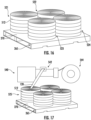
- Four cushion gum rolls may be laid flat on a pallet or skid to form a skid layer. Multiple skid layers may be positioned on a single skid or pallet. A film or buffer may be positioned between each of the skid layers.
- the cushion gum rolls are "naked," meaning that the cushion gum rolls are not wrapped in a film, and that no separators or barriers are positioned between the cushion gum rolls of the same skid layer. Once the skid includes the desired number of skid layers (e.g., 2, 3, 4, 5, etc.), the skid may be skid wrapped.
- the cushion gum rolls may be individually wrapped in a film such that a skid layer includes four individually-wrapped cushion gum rolls.
- the skid includes a top roll, positioned on top of the top skid layer to at least one of discourage or prevent stacking another skid on top of the cushion gum rolls.
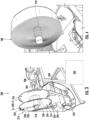
- a gum roll (e.g., cushion gum roll, adhesive roll, etc.) 100 is shown, according to an example embodiment.
- the gum roll 100 defines a generally annular body having a first side 102, a second side 104 substantially parallel to and opposite the first side 102, an inner roll surface 106, an outer roll surface 108, an inner roll diameter 110, an outer roll diameter 112, a roll thickness 114, and a center axis C A .
- the gum roll 100 substantially defines an Archimedean spiral.
- the inner roll diameter 110 may be between 5,1-15,2 cm (2-6 inches), inclusive. In some embodiments, the inner roll diameter 110 is approximately 7,6 cm (3 inches).
- the outer roll diameter 112 may be between 25,4-152,4 cm (10-60 inches). In some embodiments, the outer roll diameter 112 is between 50,8-127,0 cm (20-50 inches). inclusive. In some embodiments, the outer roll diameter 112 is between 55,9-66,0 cm (22-26 inches), inclusive. For example, the outer roll diameter 112 may be approximately 59,7 cm (23.5 inches). In some embodiments, the outer roll diameter 112 is between 101,6-116,8 cm (40-46 inches), inclusive. For example, the outer roll diameter 112 may be approximately 106,7 cm (42 inches). In some embodiments, the outer roll diameter 112 is greater than 152,4 cm (60 inches).
- the outer roll diameter 112 is sized to fit on a skid or pallet.
- the outer roll diameter 112 may be approximately equal to the size of the skid or pallet such that no portion of the gum roll 100 extends over the edge of the skid or pallet.
- the roll thickness 114 is defined as a distance between the first side 102 and the second side 104. The roll thickness 114 may vary across the entirety of the gum roll 100.
- the central axis C A is defined as the central axis of the inner roll surface 106.
- the inner roll surface 106 may define a substantially circular cross-section such that the central axis C A extends through a center of the substantially circular cross-section.
- the outer roll surface 108 defines a substantially circular cross-section and the central axis C A is also the central axis of the outer roll surface 108.
- the gum roll 100 is formed from a strip stock 120, such as a strip stock of cushion gum, adhesive, rubber cement, highly dispersed precipitated silica (HDSS), or a similar material.
- the strip stock 120 may be pre-formed before being wound into the gum roll 100.
- a strip stock 120 of HDSS may be manufactured and stored on a storage roll for a period of time (e.g., minutes, hours, days, weeks, etc.) before being unwound from the storage roll and wound into the gum roll 100.
- the gum roll 100 is formed as part of the manufacturing processes for the strip stock 120.
- a sheet of HDSS e.g., sheet stock, etc.
- This avoids the additional steps of winding the strip stock 120 onto a roller for storage, and then unwinding the roll at a later time to form the gum roll 100.
- the strip stock 120 includes a first surface 122 and a second surface 124 opposite the first surface 122 and substantially parallel to the first surface 122. A distance between the first surface 122 and the second surface 124 is shown as a stock thickness 126.
- the stock thickness 126 may be less than 7,6 cm (3 inches). In some embodiments, the stock thickness 126 is less than one inch. In some embodiments, the stock thickness 126 is between 0,64-2,54 cm (0.25-1 inches), inclusive.
- the HDSS, and thus the strip stock 120 may be pliable, malleable, and formable such that the stock thickness 126 varies across the entirety of the strip stock 120.
- the strip stock 120 is shown being wound into the gum roll 100.
- the strip stock further includes a first edge 127 and a second edge 128 opposite to the first edge 127.
- a distance between the first edge 127 and the second edge 128 is shown as a stock width 130.
- the stock width 130 may be between 7,6-20,3 cm (3-8 inches), inclusive. In some embodiments, the stock width 130 is between 12,7-15,2 cm (5-6 inches), inclusive. Similar to the stock thickness 126, the stock width 130 may vary between the first edge 127 and the second edge 128 along a length of the strip stock 120 due to manufacturing tolerances and the pliability of the HDSS. In some embodiments, the stock thickness 126 and the stock width 130 may be out of tolerance with the desired manufacturing tolerances.
- the strip stock 120 further includes a first end 134 and a second end 136.
- the first end 134 and the second end 136 are separated by a distance, referred to herein as a stock length.
- the stock length is defined as the shortest distance between the first end 134 and the second end 136 along a continuous, unbroken line that lies on the first surface 122. This is in contrast to the absolute distance between the first end 134 and the second end 136, shown in FIG. 1 as being less than the outer roll diameter 112 (e.g., approximately one-half the outer roll diameter 112 minus one-half of the inner roll diameter 110).
- the stock length may be less than 30,5 m (100 feet).
- the stock length maybe between 12,2-30,5 m (40-100 feet). In some embodiments, the stock length is greater than 30,5 m (100 feet), e.g. 36,6m (120 feet), 61,0 m (200 feet), 152,4 m (500 feet), etc.
- the gum roll 100 includes a structural support core 142 extending along the central axis C A and interfacing with the inner roll surface 106.
- the structural support core 142 may be formed of cardboard or a similar disposable material that provides support for a single gum roll 100.
- the structural support core 142 is solid and substantially rigid such that the sides of the structural support core 142 can withstand large forces without compressing or deforming.
- the structural support core 142 is a spring core, or a cylindrical sleeve that has a hollow center and is configured to be compressed during insertion and removal.
- the structural support core 142 is formed of plastic, metal, wood, or a similar material such that the structural support core 142 may be reused for multiple gum rolls.
- the gum roll 100 is coreless, meaning that the gum roll 100 does not include a structural support (e.g., the structural support core 142) positioned proximate to the inner roll surface 106.
- a structural support e.g., the structural support core 142
- the inner roll surface 106 e.g., the first surface 122 proximate to the first end 134
- the gum roll 100 is formed of the strip stock 120 such that the first surface 122 interfaces with the second surface 124.
- the strip stock 120 is coated with a powder (e.g., inert powder) or coating that prevents the strip stock 120 from adhering to itself while being wound into the gum roll 100.
- the strip stock 120 is dipped in an anti-tack emulsion prior to being wound into the gum roll 100 to prevent the strip stock 120 from sticking to itself.
- the strip stock 120 is cut and the gum roll 100 is considered to be complete.
- the gum roll 100 may include a splice 250.
- the strip stock 120 may have a strip length that is too short to form the gum roll 100 of the desired outer roll diameter 112.
- 24,4 m (80 feet) of strip stock may be required to form the gum roll 100 of the desired outer roll diameter 112, but a first strip stock may have a strip length of only 12,2 m (40 feet).
- the second end 136 of the first strip stock may be spliced with (e.g., coupled to, hot spliced, etc.) a first end of a second strip stock to form the gum roll 100 having the desired outer roll diameter 112.
- a third strip stock may be required to form the gum roll 100, the third strip stock joined to the second strip stock with a second splice.
- the gum roll 100 may include many splices that join many strip stocks (e.g., 1, 2, 3, 5, 8, etc.).
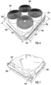
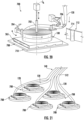
- the first winding system 200 includes a rotating spindle 204, an actuator 208, and a fixture assembly 212.
- the actuator 208 is configured to rotate the rotating spindle 204 and the fixture assembly 212.
- the fixture assembly 212 is coupled to the rotating spindle 204 such that the fixture assembly 212 rotates as the rotating spindle 204 rotates.
- the fixture assembly 212 includes a first fixture plate 214, a second fixture plate 216, and a core fixture 218.
- the first fixture plate 214, the second fixture plate 216, and the core fixture 218 are removably coupled to the rotating spindle 204 such that a central axis of the rotating spindle 204 extends through each of the first fixture plate 214, the second fixture plate 216, and the core fixture 218.
- the first fixture plate 214 and the second fixture plate 216 are separated by a distance, shown as a fixture width 220.
- the first fixture plate 214 and the second fixture plate 216 are configured to facilitate winding the gum roll 100.
- the fixture width 220 is approximately equal to the roll thickness 114.
- the first fixture plate 214 includes a fixture slot 222.
- the fixture slot 222 includes a first slot edge 224 and a second slot edge 226.
- the first slot edge 224 extends in a substantially circumferential direction with respect to a central axis of the rotating spindle 204.
- the first slot edge 224 is positioned a distance away from the central axis of the rotating spindle 204, the distance shown as a first edge radius 228.
- the second slot edge 226 extends in a substantially circumferential direction with respect to the central axis of the rotating spindle 204.
- the second slot edge 226 is concentric with the first slot edge 224.
- the second slot edge 226 is positioned radially away from the central axis of the rotating spindle 204 by a distance, shown as a second edge radius 230.
- the fixture slot 222 acts as a "Go/No Go" gauge, where the operator cuts the strip stock 120 when the gum roll 100 is visible through the fixture slot 222.
- the gum roll 100 has the desired outer roll diameter 112 when a portion of the gum roll 100 extends radially away from the central axis of the rotating spindle 204 a distance equal to or greater than the first edge radius 228, but less than or equal to the second edge radius 230.
- the first edge radius 228 is approximately 55,9 cm (22 inches) and the second edge radius 230 is approximately 58,4 cm (23 inches).
- the first winding system 200 includes a pressure roller 240.
- the pressure roller 240 is configured to apply a radial force to the gum roll 100 in a direction generally toward the central axis of the rotating spindle 204 as the strip stock 120 is wound around the core fixture 218.
- the core fixture 218 may be a cylindrical sleeve or shaft that is removably coupled to the rotating spindle 204 and is structured to withstand the radially compressive forces caused by the winding of the strip stock 120.
- the strip stock 120 is wound around the rotating spindle 204. The force applied by the pressure roller 240 may be adjusted to achieve a desired winding tension.
- the pressure roller 240 includes a sensor 242, such as an encoder, that automatically determines the outer roll diameter 112 as the strip stock 120 is wound onto the core fixture 218.
- the first winding system 200 may further include a cutting system 244 configured to cut the strip stock 120 when the sensor 242 detects that the outer roll diameter 112 is in the desired range.
- the first fixture plate 214 may be removed from the first winding system 200 such that the gum roll 100 and the core fixture 218 may be removed from the first winding system 200.
- An assisted lifting device may be used to transport the gum roll 100 from the first winding system 200 to a skid or pallet.
- the gum roll 100 may be placed on a flat transport structure (e.g., skid, pallet, etc.), referred to herein as a skid 265, such that the first side 102 is facing the top of the skid 265.
- the skid 265 may be formed of plastic, press board, metal, cardboard, wood, and the like.
- the strip stock 120 is provided.
- the strip stock 120 may be manufactured just before being wound into the gum roll 100.
- the strip stock 120 is stored on a roll for a period of time prior to being wound into the gum roll 100.
- the core fixture 218 is coupled to the rotating spindle 204 such that the core fixture 218 rotates as the rotating spindle 204 rotates.
- the core fixture 218 is a hollow tube that is centered on the rotating spindle 204.
- the core fixture 218 is an elongate bar coupled to the rotating spindle 204 at one end.
- the first end 134 of the strip stock 120 is coupled to the core fixture 218. Specifically, the first end 134 is coupled to the core fixture 218 such that the first surface 122 of the strip stock 120 interfaces with an outer surface of the core fixture 218.
- the rotating spindle 204 is rotated to wind the strip stock 120 onto the core fixture 218 to form the gum roll 100.
- the pressure roller 240 is used to facilitate the winding tension of the gum roll 100.
- the winding tension is controlled such that the gum roll 100 is formed using a constant winding tension.
- the second end 136 of the strip stock 120 is spliced to a first end of another strip stock to increase the length of the strip stock 120.
- another strip stock may be spliced to the second end 136 of the strip stock 120, and the winding of the gum roll 100 continues.
- the strip stock 120 is of adequate length and this step 310 is not required.
- the strip stock 120 (e.g., the first strip stock, the second strip stock, etc.) is cut to form the second end 136.
- the strip stock 120 may be cut when the outer roll diameter 112 reaches a desired diameter.
- the second end 136 is crimped (e.g., impressed, deformed and coupled) to the gum roll 100 to prevent the second end 136 from separating from the gum roll 100, such as during transportation.
- the core fixture 218 is removed from the rotating spindle 204.
- the gum roll 100 may be removed using an assistive lifting device, such as a fork lift, lift-assist, or a similar assistive lifting device.
- the core fixture 218 is removed from the gum roll 100 such that the inner roll surface 106 is exposed to air.
- the gum roll 100 may be laid flat on a pallet or skid before the core fixture 218 is removed from the gum roll 100.
- the gum roll 100 may be removed from the core fixture 218 without removing the core fixture 218 from the rotating spindle 204.
- the structural support core 142 is positioned within the gum roll 100 to replace the core fixture 218 and to provide support to the inner roll surface 106.
- the structural support core 142 is positioned within the gum roll 100 such that the structural support core 142 interfaces with the inner roll surface 106 of the gum roll 100.
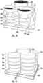
- the skid 265 is shown having a first gum roll 321, a second gum roll 322, a third gum roll 323, and a fourth gum roll 324 positioned thereon.
- Each of the first gum roll 321, the second gum roll 322, the third gum roll 323, and the fourth gum roll 324 are substantially similar to the gum roll 100. Accordingly, similar features are denoted with like numbering.
- the first gum roll 321, the second gum roll 322, the third gum roll 323, and the fourth gum roll 324 are collectively referred to as "the gum rolls 325.”
- the skid 265 defines a generally planner stacking surface 270 (e.g., first skid surface) having a skid width 272 and a skid length 274.
- the stacking surface 270 is substantially square, the skid width 272 and the skid length 274 being approximately the same length.
- the stacking surface 270 defines a polygon (e.g., regular polygon, irregular polygon) different from a square, such as a rectangle, trapezoid, rhombus, diamond, parallelogram, etc.
- the skid width 272 and the skid length 274 are different lengths.
- the skid 265 has a skid width 272 of approximately 111,8 cm (44 inches) and a skid length 274 of approximately 111,8 cm (44 inches). In some embodiments, the skid 265 has a skid width 272 of approximately 121,9 cm (48 inches) and a skid length 274 of approximately 121,9 cm (48 inches).
- each of the first gum roll 321, the second gum roll 322, the third gum roll 323, and the fourth gum roll 324 fit on the stacking surface 270 such that no portion of any of the first gum roll 321, the second gum roll 322, the third gum roll 323, and the fourth gum roll 324 extends beyond a perimeter of the stacking surface 270.
- a portion of any of the first gum roll 321, the second gum roll 322, the third gum roll 323, and the fourth gum roll 324 may extend beyond the perimeter of the stacking surface 270 and hang over the edge of the skid 265.
- the first gum roll 321 may have the outer roll diameter 112 equal to or less than one half of the skid length 274.
- each of the gum rolls 325 is defined by a substantially similar outer roll diameter 112 being approximately equal to one half of the skid length 274 such that the gum rolls 325 may be positioned on the stacking surface 270 without hanging over the edge of the skid 265.
- a first film sheet e.g., film, film barrier, etc.
- the skid 265 may be formed of a material that fuses to the strip stock 120 immediately upon contact, and thus the first film sheet 330 is configured to prevent such contact.
- the gum rolls 325 are naked and coreless , meaning that the strip stock 120 is exposed to the atmosphere when the gum rolls 325 are positioned on the stacking surface 270.
- the gum rolls 325 cooperate to form a first skid layer 332.
- the skid 265 may be configured to support many gum rolls, and thus multiple skid layers.
- a perspective view of the skid 265 having the first skid layer 332 is shown, according to another example embodiment.
- a second film sheet 334 may be positioned on top of the gum rolls 325.
- the first side 102 of each of the gum rolls 325 may interface with the first film sheet 330
- the second side 104 of each of the gum rolls 325 interfaces with the second film sheet 334.
- a fifth gum roll 335, a sixth gum roll 336, a seventh gum roll 337, and an eighth gum roll 338 may be positioned on the second film sheet 334 such that the fifth gum roll 335 is approximately concentric with the first gum roll 321, the sixth gum roll 336 is approximately concentric with the second gum roll 322, the seventh gum roll 337 is approximately concentric with the third gum roll 323, and the eighth gum roll 338 is approximately concentric with the fourth gum roll 324.
- the gum rolls 340 may be substantially similar to the gum roll 100. Collectively, the gum rolls 340 form a second skid layer 342.
- a third film sheet 344 may be positioned, shown in FIG. 8 .
- the skid 265 may be skid wrapped using poly film 714, as shown in FIG. 9 .
- film sheets e.g., the first film sheet 330, the second film sheet 334, and the third film sheet 344 are not provided between the skid layers (e.g., between the first skid layer 332 and the second skid layer 342).
- the skid 265 includes four skid layers. In some embodiments, the skid 265 includes five skid layers. In some embodiments, the skid 265 includes six skid layers. In some embodiments, the skid 265 includes ten skid layers. As shown in FIG. 10 , the skid 265 includes the first skid layer 332, the second skid layer 342, a third skid layer 346, a fourth skid layer 348, and a fifth skid layer 350. The third skid layer 346, the fourth skid layer 348, and the fifth skid layer 350 are similar to the first skid layer 332.
- the skid 265 may include most any number of skid layers (e.g., 1, 2, 3, 4, 5, etc.).
- a final gum roll 352 (similar to the gum roll 100) may be positioned on top of the top skid layer (e.g., the fifth skid layer 350) and centered relative to the stacking surface 270.
- the final gum roll 352 may be used to discourage stacking another skid pallet on top of the skid 265 loaded with five skid layers.
- each of the gum rolls positioned on the skid 265 e.g., the gum rolls 340, the gum rolls 325, the final gum roll 352) are individually wrapped.
- each of the gum rolls positioned on the skid 265 are wrapped in poly film 714.
- a skid wrapping machine or a luggage wrapping machine may be used to wrap the gum rolls.
- the skid 265 is shown having the first skid layer 332, the second skid layer 342, the third skid layer 346, the fourth skid layer 348, and the fifth skid layer 350.
- Each of the skid layers may include four gum rolls wrapped in poly film 714.
- the final gum roll 352 may be wrapped in poly film 714 and positioned on the fifth skid layer 350 and centered relative to the stacking surface 270.
- the skid 265 may be substantially rectangular such that the gum rolls are loaded on the stacking surface 270 in a 2x3 configuration. In some embodiments, the gum rolls may be loaded on the stacking surface 270 in a triangular configuration such that three gum rolls form each of the skid layers. In some embodiments, such as shown in FIG. 12 , the gum roll 100 may be formed to have an outer roll diameter 112 approximately equal to the skid length 274 such that the first skid layer 332 includes only one gum roll 100 and the gum roll 100 does not extend beyond the perimeter of the stacking surface 270.
- the gum roll 100 may be formed to have the outer roll diameter 112 measuring approximately, but not more than, 121, 9 cm (48 inches). In some embodiments, the gum roll 100 may have an outer roll diameter of 116,8 cm (46 inches). In some embodiments, the gum roll 100 has an outer diameter of between 2,54 and 5,08 cm (1 and 2 inches), inclusive, less than the shortest dimension (e.g., width, length) of the skid 265.
- the gum roll 100 may have a diameter between 106,7 and 109,2 cm (42 and 43 inches), inclusive.
- the gum roll 100 may be placed on the first film sheet 330 on the stacking surface 270, and the second film sheet 334 may be placed on top of the gum roll 100 such that the gum roll 100 forms the entirely of the first skid layer 332.
- the skid 265 may include 2, 3, 4, 5, or more such gum rolls such that the skid 265 includes five or more skid layers, each of the skid layers formed of a single gum roll.
- the skid 265 includes the final gum roll 352.
- the final gum roll 352 may define the outer roll diameter 112 less than the skid width 272. In some embodiments, the outer roll diameter 112 is approximately 40-60% of the skid width 272, inclusive.
- the skid 265 having the stacking surface 270 is provided.
- the stacking surface 270 may be most any shape or size configured to receive the gum roll 100.
- the stacking surface 270 is round such that material may be saved in the manufacturing of the skid 265.
- the first film sheet 330 is positioned on the stacking surface 270.
- the first film sheet 330 may be formed of a polymer, an elastomer, or a similar material.
- the first film sheet 330 is treated or coated such that the first film sheet 330 is resistant to curing to, sticking to, or permanently adhering to the gum roll 100.
- the film sheet 330 is not provided.
- the gum roll 100 may be sized to have a diameter that is 2,54-7,62 cm (1-3 inches) less than one of the stacking width 272 or the stacking length 274.
- the gum roll 100 is sized to have an outer roll diameter 112 that is between 2,54-5,08 cm (1-2 inches) less than at least one of the stacking width 272 or the stacking length 274.
- the diameter of the gum roll 100 may be between 116,8-119,4 cm (46-47 inches).
- the gum roll 100 is provided on the first film sheet 330 such that no portion of the gum roll 100 extends beyond the perimeter of the stacking surface 270.
- the first side 102 (or second side 104) is positioned entirely on the first film sheet 330.
- the gum rolls 325 are positioned in a 2x2 (two-by-two) configuration on the skid 265 such that no portion of any one of the gum rolls 325 extends beyond the perimeter of the stacking surface 270.
- the first side 102 is positioned on the stacking surface 270.
- the first side 102 is positioned entirely on the stacking surface 270.
- the first skid layer 332 is formed on the first film sheet 330.
- the second gum roll 322 is positioned on the stacking surface, abutting the first gum roll 321.
- the first skid layer 332 may be formed only of naked, coreless gum rolls, such as the gum roll 100.
- the gum rolls 325 form the first skid layer 332 and a divider is positioned between each of the gum rolls 325 to prevent any one of the gum rolls 325 from contacting another one of the gum rolls 325.
- each one of the gum rolls 325 is individually wrapped in poly film 714.
- the gum rolls 325 are individually wrapped in poly film before the gum rolls 325 are positioned on the stacking surface 270 to form the first skid layer 332.
- the second film sheet 334 is positioned on the first skid layer 332 such that the first skid layer 332 is prevented from contacting the second skid layer 342.
- steps 408 and 410 may be repeated until the desired number of skid layers is formed.
- the second film sheet 334 is not provided and the gum rolls 325 of the first skid layer 332 are able to interface with the gum rolls of the second skid layer 342.
- the final gum roll 352 similar to the gum roll 100, is positioned on the final skid layer (e.g., the fifth skid layer 350) and centered relative to the stacking surface 270.
- the final gum roll 352 is positioned to discourage stacking another pallet or skid on top of the skid 265.
- the skid layers (e.g., the first skid layer 332 and the second skid layer 342) are skid wrapped, such as using poly film 714 or similar material to wrap the skid layers and prevent shifting of the gum rolls during shipping.
- the second winding system 500 includes a core fixture 502, a rotating spindle 504, a handle 506, and a support stand 508.
- the second winding system 500 is configured to wind the strip stock 120 into the gum roll 100 (e.g., the gum rolls 325).
- the strip stock 120 may be formed as a sheet stock 140 prior to being scored or cut into the strip stock 120.
- the sheet stock 140 has a width approximately equal to five times the stock width 130.
- the sheet stock 140 may include an incision 123 (e.g., cut, score, partial cut, perforation, etc.), each incision 123 corresponding to an edge of the strip stock 120.
- the sheet stock 140 may be coupled to the core fixture 502 and wound onto the core fixture such that an elongate roll 510 is formed, the elongate roll 510 including multiple gum rolls.
- the sheet stock 140 may have a width approximately equal to five times the stock width 130 and the sheet stock may include four incisions 512, the incisions 512 facilitating separation of the strip stock 120 from the sheet stock 140, but the incisions 512 not fully separating the strip stock 120 from the sheet stock 140.
- the sheet stock 140 is wound onto the core fixture 502, the core fixture 502 defining a length 514 greater than the width of the sheet stock 140 such that no portion of the sheet stock 140, and similarly no portion of the elongate roll 510, extends beyond the ends of the core fixture 502.
- the incisions 512 extend all the way through the sheet stock 140 and separate the sheet stock 140 into individual strip stocks 120.
- the individual strip stock 120 may be wound on the core fixture 502 in close proximity to one another forming individual gum rolls 100 that are not coupled to one another.
- the core fixture 502 is removably coupled to the rotating spindle 504 such that the core fixture 502 may be removed from the second winding system 500 when the elongate roll 510 is at a desired diameter.
- the rotating spindle 504 is operatively coupled to the handle 506.
- the handle 506 is rotated by hand, such as by an operator, to facilitate winding of the elongate roll 510 onto the core fixture 502.
- the rotating spindle 504 is operatively coupled to an actuator configured to rotate the rotating spindle 504 and wind the sheet stock 140 on the core fixture 502.
- the core fixture 502, the rotating spindle 504, and the handle 506 are all supported by the support stand 508.
- the elongate roll 510 is shown positioned on the skid 265.
- a lifting device such as a robotic arm or fork lift may transfer the elongate roll 510 from the second winding system 500 to the skid 265.
- the elongate roll 510 may be rotated sideways such that the core fixture 502 extends substantially perpendicular relative to the stacking surface 270.
- the elongate roll 510 may then be positioned on the skid 265 and the core fixture 502 may be removed from the elongate roll 510.
- the elongate roll 510 may be positioned on the skid 265 without separating the individual gum rolls 100 from the elongate roll 510 via the incisions 512.
- the skid 265 may include the first film sheet 330 between the elongate roll 510 and the stacking surface 270, and the skid may include the second film sheet 334 on top of the elongate roll 510.
- the skid 265 includes one elongate roll 510 positioned on the skid 265 and centered on the skid 265 relative to the stacking surface 270.
- the diameter of the elongate roll 510 may be slightly less than the skid length 274 and less than the skid width 272.
- the skid 265 includes a first elongate roll 521, a second elongate roll 522, a third elongate roll 523, and a fourth elongate roll 524, herein referred to collectively as the elongate rolls 525.
- the elongate rolls 525 may be positioned on the skid 265 in a two-by-two configuration. After the elongate rolls 525 are positioned on the skid 265, the elongate rolls 525 may be skid wrapped to prevent the elongate rolls 525 from shifting during shipping.
- the elongate roll 510 is shown as including four incisions 512 and five gum rolls 100, the elongate roll 510 may include any number of incisions 512 or gum rolls 100 (e.g., two gum rolls 100 and one incision 512, three gum rolls 100 and two incisions, six gum rolls 100 and five incisions 512, etc.).
- the skid 265 having the elongate rolls 525 is shown in a retreading environment.
- a retreading system 540 including an extruder 542.
- the strip stock 120 is fed into the extruder 542, which then applies the strip stock 120 to a tire casing 544 during a retreading operation.
- the extruder 542 is configured to receive the strip stock 120 and extrude the strip stock 120 through a die, tube, or similar structure.
- the strip stock 120 is then applied to the tire casing 544 during a retread process.
- extruding the strip stock 120 including heating up the strip stock 120 to activate the adhesive (e.g., tackifying) agents that cause the strip stock 120 to adhere to the tire casing 544.
- the first end 134 is fed into the extruder 542.
- the strip stock 120 from the gum roll 100 is "center-fed.”
- the second end 136 is fed into the extruder 542.
- the gum roll 100 may still be coupled to the elongate roll 510 when the first end 134 is fed into the extruder 542.
- the incision 512 may be a perforation that allows separation between the strip stock 120 of the gum roll 100 and the strip stock 120 of the adjacent gum roll when a predetermined force is applied, such as by the extruder 542.
- An operator may grab the first end 134 and separate the strip stock 120 proximate the first end 134 from the adjacent gum roll by pulling on the first end 134.
- the strip stock 120 may separate from the adjacent gum roll along the incision 512. After the entire gum roll 100 has been used, the same process may be applied to the adjacent gum roll.
- the third winding system 600 is similar to the second winding system 500. A difference between the third winding system 600 and the second winding system 500 is that the third winding system 600 does not include the handle 506.
- the third winding system 600 includes a pair of drive rollers 604 configured to wind the sheet stock 140 into the elongate roll 510.
- the pair of drive rollers 604 interface with second surface 124 of the strip stock 120 (e.g., the second surface 124 of the sheet stock 140) and wind the sheet stock 140 into the elongate roll 510.
- the gum roll 100 is shown on a conveyor 610.
- the gum roll 100 travels down the conveyor 610 and is received by a wrapping system 615 configured to wrap the gum roll 100.
- the gum roll 100 may be wrapped in poly film 714 to prevent damage to the gum roll 100 during packaging and shipping. After the gum roll 100 is wrapped in poly film 714, the gum roll 100 is placed on the skid 265.
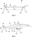
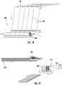
- a fourth winding system 700 is shown according to an example embodiment.
- the fourth winding system 700 is configured to wind the gum roll 100 substantially horizontally such that the central axis C A is substantially parallel to gravity while the gum roll 100 is wound.
- the fourth winding system 700 includes a core fixture 702, a pressure roller 704, guide rollers 706, a rotating platform 708, and an actuator 710.
- the fourth winding system 700 is configured to wind the gum roll 100 directly on the skid 265, removing the intermediate step of having to rotate the gum roll 100 such that one of the first side 102 or the second side 104 is substantially parallel to the stacking surface 270.
- the fourth winding system 700 winds all of the skid layers (e.g., five skid layers) at the same time.
- the first end 134 may be coupled to the core fixture 702.
- the guide rollers 706 facilitate the positioning of the strip stock 120 to prevent the strip stock 120 from twisting or tearing during the winding of the gum roll 100.
- the strip stock 120 is initially fed in a vertical direction (e.g., the first edge 127 and the second edge 128 are substantially perpendicular to the skid 265).
- the guide rollers 706 redirect the strip stock 120 such that the strip stock 120 may be wound into the gum roll 100 in a horizontal direction.
- the guide rollers 706 may facilitate a substantially 90-degree turn in the feed direction of the strip stock 120 such that the first edge 127 and the second edge 128 are substantially parallel to the stacking surface 270.
- the guide rollers 706 may redirect a feed direction of the sheet stock 140, such as if the sheet stock 140 is to be wound onto the core fixture 702 such that the elongate roll 510 is formed on the skid 265.
- the skid 265 is placed on and may be coupled to the rotating platform 708 such that the skid 265 rotates as the rotating platform 708 rotates.
- the core fixture 702 rotates as the rotating platform 708 rotates.
- the first end 134 of the strip stock 120 may be coupled to the core fixture 702 such that the first surface 122 proximate to the first end 134 interfaces with the core fixture 702.
- the pressure roller 704 may interface with the second surface 124 of the strip stock 120 to maintain a consistent winding tension of the gum roll 100.
- the core fixture 702 is positioned proximate to a center of the stacking surface 270 such that the gum roll 100 is centered on the skid 265 relative to the stacking surface 270.
- a sleeve is provided around the core fixture 702 to facilitate removal of the core fixture 702 from the gum roll 100.
- the core fixture 702 is retractable such that after the gum roll 100 is formed, the core fixture 702 may be pulled upward away from the skid 265 and out of the middle of the gum roll 100 while sleeve remains positioned within the gum roll 100.
- the strip stock 120 may be cut to form the second end 136.
- the first end 134 formed by the cut may be coupled to the core fixture 702 proximate to where the gum roll 100 is coupled to the core fixture 702.
- the process may be repeated to form a second gum roll on top of the gum roll 100 that was formed on the skid 265.
- the second film sheet 334 may be positioned between the second gum roll and the gum roll 100.
- the gum roll 100 forms the first skid layer 332.
- the skid 265 may include multiple skid layers (e.g., the first skid layer 332 and the second skid layer 342) until the desired amount of skid layers are formed or until the load capacity of the skid 265 is achieved.
- the skid 265 includes ten skid layers.
- the final gum roll 352 is positioned on the final skid layer (e.g., the fifth skid layer 350, a sixth skid layer, an eight skid layer, etc.) to discourage stacking another pallet or skid on the skid 265.
- the final skid layer e.g., the fifth skid layer 350, a sixth skid layer, an eight skid layer, etc.
- the skid layers may be skid wrapped.
- the skid layers are skid wrapped using a poly film roller 712.
- the poly film 714 may be coupled to the skid layers, and the rotating platform 708 may rotate to unwind the poly film 714 from the poly film roller 712 and wind the poly film 714 on the skid layers.
- the core fixture 702 may be removed from the skid layers before or after the skid layers are skid wrapped.
- the sheet stock 140 is shown as including five strip stocks 120 and four incisions 512. As the sheet stock 140 is fed toward the plurality of fourth winding systems 700, the sheet stock 140 may be separated into the strip stock 120 along the incisions 512. All five of the shown fourth winding systems 700 may operate to wind the strip stock 120 at the same time such that the sheet stock 140 is wound into five of the gum rolls 100 at the same time.
- Coupled means the joining of two members directly or indirectly to one another. Such joining may be stationary (e.g., permanent) or moveable (e.g., removable or releasable). Such joining may be achieved with the two members or the two members and any additional intermediate members being integrally formed as a single unitary body with one another or with the two members or the two members and any additional intermediate members being attached to one another.
Landscapes
- Engineering & Computer Science (AREA)
- Mechanical Engineering (AREA)
- Winding Of Webs (AREA)
- Packaging Of Machine Parts And Wound Products (AREA)
Claims (14)
- Verfahren zum Ausbilden einer Gummirolle (100, 321, 322, 323, 324, 325, 335, 336, 337, 338, 340, 352, 510, 521, 522, 523, 524, 525), das Verfahren umfassend:Bereitstellen eines Streifenmaterials (120, 140), das ein erstes Ende (134), eine erste Oberfläche (122) und eine zweite Oberfläche (124) gegenüber der ersten Oberfläche (122) aufweist;Koppeln des ersten Endes (134) mit einer Kernvorrichtung (218, 502, 702), so dass die erste Oberfläche (122) mit der Kernvorrichtung (218, 502, 702) in Verbindung steht;Drehen der Kernvorrichtung (218, 502, 702), um das Streifenmaterial (120, 140) auf die Kernvorrichtung (218, 502, 702) derart zu wickeln, dass die erste Oberfläche (122) mit der zweiten Oberfläche (124) in Verbindung steht, um eine Gummirolle (100, 321, 322, 323, 324, 325, 335, 336, 337, 338, 340, 352, 510, 521, 522, 523, 524, 525) auszubilden; undEntfernen der Kernvorrichtung (218, 502, 702) von der Gummirolle (100, 321, 322, 323, 324, 325, 335, 336, 337, 338, 340, 352, 510, 521, 522, 523, 524, 525).
- Verfahren nach Anspruch 1, ferner umfassend Schneiden des Streifenmaterials (120, 140), um ein zweites Ende (136) auszubilden, wenn die Gummirolle (100, 321, 322, 323, 324, 325, 335, 336, 337, 338, 340, 352, 510, 521, 522, 523, 524, 525) auf einen äußeren Rollendurchmesser (112) gewickelt ist, wobei der äußere Rollendurchmesser (112) größer als ein Durchmesser der Kernvorrichtung (218, 502, 702) ist.
- Verfahren nach Anspruch 2, ferner umfassend Heften des zweiten Endes (136) an die Gummirolle (100, 321, 322, 323, 324, 325, 335, 336, 337, 338, 340, 352, 510, 521, 522, 523, 524, 525).
- Verfahren nach Anspruch 2, wobei der äußere Rollendurchmesser (112) zwischen 25,4-152,4 cm (10-60 Zoll), einschließlich, liegt.
- Verfahren nach Anspruch 2, wobei der äußere Rollendurchmesser (112) zwischen 50,8-127 cm (20-50 Zoll), einschließlich, liegt.
- Verfahren nach Anspruch 1, ferner umfassend Einsetzen eines strukturellen Stützkerns (142) in die Gummirolle (100, 321, 322, 323, 324, 325, 335, 336, 337, 338, 340, 352, 510, 521, 522, 523, 524, 525), wobei der strukturelle Stützkern (142) mit der ersten Oberfläche (122) in Verbindung steht.
- Verfahren nach Anspruch 1, wobei das Streifenmaterial (120, 140) aus hoch dispergierbaren ausgefällten Kieselsäuren ausgebildet ist.
- Verfahren nach Anspruch 1, ferner umfassend Einwickeln der Gummirolle (100, 321, 322, 323, 324, 325, 335, 336, 337, 338, 340, 352, 510, 521, 522, 523, 524, 525) in Polyfolie (714).
- Verfahren nach Anspruch 1, ferner umfassend:Bereitstellen eines Gestells (265), das eine Stapeloberfläche (270) aufweist;Positionieren der Kernvorrichtung (218, 502, 702) auf der Stapeloberfläche (270), wobei eine Mittelachse der Kernvorrichtung (218, 502, 702) sich im Wesentlichen senkrecht zu der Stapeloberfläche (270) erstreckt; undDrehen des Gestells (265) und der Kernvorrichtung (218, 502, 702), um das Streifenmaterial (120, 140) auf das Gestell (265) zu wickeln, wobei die erste Oberfläche (122) des Streifenmaterials (120, 140) sich im Wesentlichen senkrecht zu der Stapeloberfläche (270) erstreckt.
- Verfahren nach Anspruch 1, wobei die Gummirolle (100, 321, 322, 323, 324, 325, 335, 336, 337, 338, 340, 352, 510, 521, 522, 523, 524, 525) eine erste Seite (102) und eine zweite Seite (104) einschließt, das Verfahren ferner umfassend:Bereitstellen eines Gestells (265), das eine Stapeloberfläche (270) aufweist;Positionieren der Gummirolle (100, 321, 322, 323, 324, 325, 335, 336, 337, 338, 340, 352, 510, 521, 522, 523, 524, 525) auf der Stapeloberfläche (270) derart, dass die erste Seite (102) auf der Stapeloberfläche (270) positioniert ist.
- Verfahren nach Anspruch 10, wobei die Stapeloberfläche (270) eine Oberflächenbreite (272) und eine Oberflächenlänge (274) einschließt, das Verfahren ferner umfassend das Ausbilden der Gummirolle (100, 321, 322, 323, 324, 325, 335, 336, 337, 338, 340, 352, 510, 521, 522, 523, 524, 525) derart, dass der äußere Rollendurchmesser (112) zwischen 2,54-7,62 cm (1-3 Zoll) kleiner als mindestens eine der Oberflächenbreite (272) oder der Oberflächenlänge (274) ist.
- Verfahren nach Anspruch 10, wobei die Gummirolle (100, 321, 322, 323, 324, 325, 335, 336, 337, 338, 340, 352, 510, 521, 522, 523, 524, 525) eine erste Gummirolle (100, 312, 335, 510, 521) ist, das Verfahren ferner umfassend Positionieren einer zweiten Gummirolle (322, 323, 324, 336, 337, 338, 510, 522, 523, 524) auf der Stapeloberfläche (270) derart, dass die zweite Gummirolle (322, 323, 324, 336, 337, 338, 510, 522, 523, 524) an der ersten Gummirolle (100, 312, 335, 510, 521) anliegt.
- Verfahren nach Anspruch 12, ferner umfassend individuelles Einwickeln sowohl der ersten Gummirolle (100, 312, 335, 510, 521) als auch der zweiten Gummirolle (322, 323, 324, 336, 337, 338, 510, 522, 523, 524) in Polyfolie (714) vor dem Positionieren der ersten Gummirolle (100, 312, 335, 510, 521) und der zweiten Gummirolle (322, 323, 324, 336, 337, 338, 510, 522, 523, 524) auf dem Gestell (265).
- Verfahren nach Anspruch 10, wobei die Gummirolle (100, 321, 322, 323, 324, 325, 335, 336, 337, 338, 340, 352, 510, 521, 522, 523, 524, 525) eine erste Gummirolle (100, 312, 335, 510, 521) ist, das Verfahren ferner umfassend:Positionieren einer Folienbarriere (330, 334, 344) auf der zweiten Seite (104) der ersten Gummirolle (100, 312, 335, 510, 521); undPositionieren einer zweiten Gummirolle (322, 323, 324, 336, 337, 338, 510, 522, 523, 524) auf der Folienbarriere (330, 334, 344) und auf der ersten Gummirolle (100, 312, 335, 510, 521).
Applications Claiming Priority (1)
| Application Number | Priority Date | Filing Date | Title |
|---|---|---|---|
| US202063076223P | 2020-09-09 | 2020-09-09 |
Publications (2)
| Publication Number | Publication Date |
|---|---|
| EP3967482A1 EP3967482A1 (de) | 2022-03-16 |
| EP3967482B1 true EP3967482B1 (de) | 2025-05-14 |
Family
ID=77710572
Family Applications (1)
| Application Number | Title | Priority Date | Filing Date |
|---|---|---|---|
| EP21195850.9A Active EP3967482B1 (de) | 2020-09-09 | 2021-09-09 | Verfahren zur herstellung von einer gummi-rolle |
Country Status (2)
| Country | Link |
|---|---|
| US (2) | US11981502B2 (de) |
| EP (1) | EP3967482B1 (de) |
Family Cites Families (24)
| Publication number | Priority date | Publication date | Assignee | Title |
|---|---|---|---|---|
| US3877655A (en) * | 1972-04-17 | 1975-04-15 | Felix G Cardinal | System, method and apparatus for processing raw rubber into strip stock for retreading tires |
| US4155519A (en) * | 1977-10-17 | 1979-05-22 | Price John E | Findings structure |
| US4757950A (en) | 1987-08-21 | 1988-07-19 | Sandar Industries, Inc. | Apparatus and method for cutting and spooling a web of paper |
| JP2510570Y2 (ja) * | 1989-09-04 | 1996-09-11 | 富士写真フイルム株式会社 | ロ―ル状写真感光材料の集合包装体 |
| DE9109284U1 (de) * | 1991-07-27 | 1991-09-26 | EMTEC Magnetics GmbH, 67059 Ludwigshafen | Mehrweg-Sammelverpackung für gestapelte Wickelrollen |
| US5256232A (en) | 1992-07-27 | 1993-10-26 | Eastman Kodak Company | Apparatus and method for winding strips of web material onto spools |
| US5351825A (en) * | 1992-12-31 | 1994-10-04 | Badger Plug Company | Packaging plug with conical nose |
| CN1050323C (zh) | 1993-08-05 | 2000-03-15 | Az造型和机械制造有限公司 | 轮胎翻新设备及方法 |
| US5368157A (en) * | 1993-10-29 | 1994-11-29 | Baldwin Graphic Systems, Inc. | Pre-packaged, pre-soaked cleaning system and method for making the same |
| US5472089A (en) | 1994-05-03 | 1995-12-05 | Eastman Kodak Company | Light-tight and physically protected packaging for a roll of photosensitive web |
| FR2763321B1 (fr) | 1997-05-13 | 1999-07-23 | Thimon | Machine pour bobiner du film, procede de fabrication de bobines de films pre-etires et bobines de films pre-etires obtenues par ledit procede |
| US6047523A (en) * | 1998-03-18 | 2000-04-11 | Tenneco Packaging Inc. | Vertical packaging of webbing rolls |
| AU6264899A (en) * | 1999-09-23 | 2001-04-24 | Goodyear Tire And Rubber Company, The | Storage spool with coiled liner |
| DE19957990A1 (de) * | 1999-12-02 | 2001-06-07 | Voith Paper Patent Gmbh | Auszieheinrichtung für in Rollenwickelmaschinen eingesetzte Wickelrohre |
| US6899778B1 (en) | 2000-01-27 | 2005-05-31 | Bandag Incorporated | Method and apparatus for preparing tire tread for a retread tire |
| BR0200346A (pt) | 2001-02-20 | 2002-10-08 | Goodyear Tire & Rubber | Método e aparelho para armazenar material em tira |
| US6581763B2 (en) * | 2001-10-18 | 2003-06-24 | Olympic General Corporation | Packaging system for coiled goods |
| ITTO20060102A1 (it) * | 2006-02-14 | 2007-08-15 | Bridgestone Corp | Metodo ed impianto per la realizzazione di una striscia di battistrada |
| DE102006007332A1 (de) | 2006-02-16 | 2007-08-30 | Schoeller Arca Systems Services Gmbh | Mehrfach verwendbare Transporteinheit für Folienrollen und dergleichen |
| JP2008169002A (ja) * | 2007-01-12 | 2008-07-24 | Bridgestone Corp | 長尺部材の巻取装置及び製造装置 |
| GB2464136A (en) | 2008-10-06 | 2010-04-07 | Dsi Dimona Silica Ind Ltd | A dispersible silica characterised by DBP absorption capacity |
| FR2939724B1 (fr) | 2008-12-17 | 2012-04-13 | Michelin Soc Tech | Bandage pneumatique dont le sommet est pourvu d'une couche anti-bruit. |
| WO2016103077A1 (en) * | 2014-12-24 | 2016-06-30 | Pirelli Tyre S.P.A. | Plant for collecting or dispensing an elongated element for building tyres and method for collecting or dispensing an elongated element wound in reels |
| JP2020070042A (ja) * | 2018-10-30 | 2020-05-07 | 株式会社フジシール | ラベルロール梱包体 |
-
2021
- 2021-09-09 US US17/470,336 patent/US11981502B2/en active Active
- 2021-09-09 EP EP21195850.9A patent/EP3967482B1/de active Active
-
2024
- 2024-03-27 US US18/617,816 patent/US20240228156A1/en active Pending
Also Published As
| Publication number | Publication date |
|---|---|
| EP3967482A1 (de) | 2022-03-16 |
| US20220073265A1 (en) | 2022-03-10 |
| US11981502B2 (en) | 2024-05-14 |
| US20240228156A1 (en) | 2024-07-11 |
Similar Documents
| Publication | Publication Date | Title |
|---|---|---|
| JP4523601B2 (ja) | タイヤの成型方法及び成型設備 | |
| EP1256541A2 (de) | Aufgewickelte Materialbahn und Verfahren zum Aufwickeln | |
| BR112017007990B1 (pt) | Processo e aparelho para aplicar um elemento de redução de ruído a um pneu para rodas de veículo | |
| ITMI20112269A1 (it) | Metodo per controllare la deposizione di uno strato di materiale polimerico sigillante su un tamburo di formatura e processo per produrre pneumatici auto-sigillanti per ruote di veicoli | |
| JP2005081845A (ja) | トレッドベルト構造を組み立ててそれを移送する方法および装置 | |
| EP3967482B1 (de) | Verfahren zur herstellung von einer gummi-rolle | |
| JP3742449B2 (ja) | カレンダ加工装置及びカレンダローラを備えているカレンダ加工装置の1つのカレンダローラを交換する方法 | |
| USRE36687E (en) | Method and apparatus for making pallet supports and pallets incorporating said supports | |
| US9950894B2 (en) | Device for receiving an elastomer strand and for feeding the elastomer strand to a processing device | |
| EP0431922B1 (de) | Einwickeln von rollenartigen Gegenständen | |
| CN100395101C (zh) | 制造充气轮胎的方法和设备 | |
| FI3746388T3 (en) | DEVICE FOR WINDING UP AND UNWINDING A NUMBER OF DIFFERENT TAPE ROLLS | |
| EP4166488B1 (de) | Kunststofffolienrolle mit konvolut-kartonrohr | |
| JP4532549B2 (ja) | カーカスプライの製造方法 | |
| US4707968A (en) | Method and apparatus for wrapping pressure sensitive rolls of material | |
| JP6641666B2 (ja) | プライの製造装置および製造方法 | |
| JP2001232694A (ja) | 未加硫タイヤのカーカスの成型方法 | |
| JP4617769B2 (ja) | 帯状部材の接合方法と帯状部材の接合装置 | |
| JP2001232696A (ja) | 未加硫タイヤのインナーライナの成型方法 | |
| JPH08156129A (ja) | 帯状材料の供給,貼付け方法 | |
| US20050183815A1 (en) | Tire ply forming apparatus and process | |
| US20260077977A1 (en) | Corewinder To Form A Log Core, Process To Form Such A Core, And Tissue Paper Logs With Said Core | |
| EP1345755B1 (de) | Verfahren und vorrichtung zur herstellung von luftreifen | |
| JPS6351881B2 (de) | ||
| JP4571552B2 (ja) | 樹脂フィルムの送給方法およびそれに用いる装置 |
Legal Events
| Date | Code | Title | Description |
|---|---|---|---|
| PUAI | Public reference made under article 153(3) epc to a published international application that has entered the european phase |
Free format text: ORIGINAL CODE: 0009012 |
|
| STAA | Information on the status of an ep patent application or granted ep patent |
Free format text: STATUS: REQUEST FOR EXAMINATION WAS MADE |
|
| 17P | Request for examination filed |
Effective date: 20210909 |
|
| AK | Designated contracting states |
Kind code of ref document: A1 Designated state(s): AL AT BE BG CH CY CZ DE DK EE ES FI FR GB GR HR HU IE IS IT LI LT LU LV MC MK MT NL NO PL PT RO RS SE SI SK SM TR |
|
| STAA | Information on the status of an ep patent application or granted ep patent |
Free format text: STATUS: EXAMINATION IS IN PROGRESS |
|
| 17Q | First examination report despatched |
Effective date: 20240221 |
|
| GRAP | Despatch of communication of intention to grant a patent |
Free format text: ORIGINAL CODE: EPIDOSNIGR1 |
|
| STAA | Information on the status of an ep patent application or granted ep patent |
Free format text: STATUS: GRANT OF PATENT IS INTENDED |
|
| RIC1 | Information provided on ipc code assigned before grant |
Ipc: B65H 19/29 20060101ALI20241105BHEP Ipc: B65H 19/22 20060101ALI20241105BHEP Ipc: B65H 18/00 20060101ALI20241105BHEP Ipc: B29D 30/00 20060101AFI20241105BHEP |
|
| INTG | Intention to grant announced |
Effective date: 20241205 |
|
| GRAJ | Information related to disapproval of communication of intention to grant by the applicant or resumption of examination proceedings by the epo deleted |
Free format text: ORIGINAL CODE: EPIDOSDIGR1 |
|
| STAA | Information on the status of an ep patent application or granted ep patent |
Free format text: STATUS: EXAMINATION IS IN PROGRESS |
|
| GRAP | Despatch of communication of intention to grant a patent |
Free format text: ORIGINAL CODE: EPIDOSNIGR1 |
|
| INTC | Intention to grant announced (deleted) | ||
| RIN1 | Information on inventor provided before grant (corrected) |
Inventor name: TOMTSCHIK, ALEXANDER G. Inventor name: ZECK, CHAD M. Inventor name: SCHURR, JEROD E. Inventor name: SCHLAPKOHL, MERLE R. Inventor name: FOSS, TIMOTHY T. Inventor name: AUDAS, MILTON B. |
|
| STAA | Information on the status of an ep patent application or granted ep patent |
Free format text: STATUS: GRANT OF PATENT IS INTENDED |
|
| INTG | Intention to grant announced |
Effective date: 20250227 |
|
| GRAS | Grant fee paid |
Free format text: ORIGINAL CODE: EPIDOSNIGR3 |
|
| GRAA | (expected) grant |
Free format text: ORIGINAL CODE: 0009210 |
|
| STAA | Information on the status of an ep patent application or granted ep patent |
Free format text: STATUS: THE PATENT HAS BEEN GRANTED |
|
| P01 | Opt-out of the competence of the unified patent court (upc) registered |
Free format text: CASE NUMBER: APP_11222/2025 Effective date: 20250306 |
|
| AK | Designated contracting states |
Kind code of ref document: B1 Designated state(s): AL AT BE BG CH CY CZ DE DK EE ES FI FR GB GR HR HU IE IS IT LI LT LU LV MC MK MT NL NO PL PT RO RS SE SI SK SM TR |
|
| REG | Reference to a national code |
Ref country code: GB Ref legal event code: FG4D |
|
| REG | Reference to a national code |
Ref country code: CH Ref legal event code: EP |
|
| REG | Reference to a national code |
Ref country code: DE Ref legal event code: R096 Ref document number: 602021030713 Country of ref document: DE |
|
| REG | Reference to a national code |
Ref country code: IE Ref legal event code: FG4D |
|
| REG | Reference to a national code |
Ref country code: NL Ref legal event code: FP |
|
| PGFP | Annual fee paid to national office [announced via postgrant information from national office to epo] |
Ref country code: NL Payment date: 20250820 Year of fee payment: 5 |
|
| PG25 | Lapsed in a contracting state [announced via postgrant information from national office to epo] |
Ref country code: FI Free format text: LAPSE BECAUSE OF FAILURE TO SUBMIT A TRANSLATION OF THE DESCRIPTION OR TO PAY THE FEE WITHIN THE PRESCRIBED TIME-LIMIT Effective date: 20250514 Ref country code: PT Free format text: LAPSE BECAUSE OF FAILURE TO SUBMIT A TRANSLATION OF THE DESCRIPTION OR TO PAY THE FEE WITHIN THE PRESCRIBED TIME-LIMIT Effective date: 20250915 Ref country code: ES Free format text: LAPSE BECAUSE OF FAILURE TO SUBMIT A TRANSLATION OF THE DESCRIPTION OR TO PAY THE FEE WITHIN THE PRESCRIBED TIME-LIMIT Effective date: 20250514 |
|
| PGFP | Annual fee paid to national office [announced via postgrant information from national office to epo] |
Ref country code: DE Payment date: 20250820 Year of fee payment: 5 |
|
| REG | Reference to a national code |
Ref country code: LT Ref legal event code: MG9D |
|
| PG25 | Lapsed in a contracting state [announced via postgrant information from national office to epo] |
Ref country code: GR Free format text: LAPSE BECAUSE OF FAILURE TO SUBMIT A TRANSLATION OF THE DESCRIPTION OR TO PAY THE FEE WITHIN THE PRESCRIBED TIME-LIMIT Effective date: 20250815 Ref country code: NO Free format text: LAPSE BECAUSE OF FAILURE TO SUBMIT A TRANSLATION OF THE DESCRIPTION OR TO PAY THE FEE WITHIN THE PRESCRIBED TIME-LIMIT Effective date: 20250814 |
|
| PG25 | Lapsed in a contracting state [announced via postgrant information from national office to epo] |
Ref country code: PL Free format text: LAPSE BECAUSE OF FAILURE TO SUBMIT A TRANSLATION OF THE DESCRIPTION OR TO PAY THE FEE WITHIN THE PRESCRIBED TIME-LIMIT Effective date: 20250514 |
|
| PGFP | Annual fee paid to national office [announced via postgrant information from national office to epo] |
Ref country code: IT Payment date: 20250820 Year of fee payment: 5 |
|
| REG | Reference to a national code |
Ref country code: AT Ref legal event code: MK05 Ref document number: 1794470 Country of ref document: AT Kind code of ref document: T Effective date: 20250514 |
|
| PG25 | Lapsed in a contracting state [announced via postgrant information from national office to epo] |
Ref country code: BG Free format text: LAPSE BECAUSE OF FAILURE TO SUBMIT A TRANSLATION OF THE DESCRIPTION OR TO PAY THE FEE WITHIN THE PRESCRIBED TIME-LIMIT Effective date: 20250514 |
|
| PGFP | Annual fee paid to national office [announced via postgrant information from national office to epo] |
Ref country code: BE Payment date: 20250820 Year of fee payment: 5 |
|
| PG25 | Lapsed in a contracting state [announced via postgrant information from national office to epo] |
Ref country code: HR Free format text: LAPSE BECAUSE OF FAILURE TO SUBMIT A TRANSLATION OF THE DESCRIPTION OR TO PAY THE FEE WITHIN THE PRESCRIBED TIME-LIMIT Effective date: 20250514 |
|
| PG25 | Lapsed in a contracting state [announced via postgrant information from national office to epo] |
Ref country code: AT Free format text: LAPSE BECAUSE OF FAILURE TO SUBMIT A TRANSLATION OF THE DESCRIPTION OR TO PAY THE FEE WITHIN THE PRESCRIBED TIME-LIMIT Effective date: 20250514 |
|
| PG25 | Lapsed in a contracting state [announced via postgrant information from national office to epo] |
Ref country code: RS Free format text: LAPSE BECAUSE OF FAILURE TO SUBMIT A TRANSLATION OF THE DESCRIPTION OR TO PAY THE FEE WITHIN THE PRESCRIBED TIME-LIMIT Effective date: 20250814 |
|
| PG25 | Lapsed in a contracting state [announced via postgrant information from national office to epo] |
Ref country code: IS Free format text: LAPSE BECAUSE OF FAILURE TO SUBMIT A TRANSLATION OF THE DESCRIPTION OR TO PAY THE FEE WITHIN THE PRESCRIBED TIME-LIMIT Effective date: 20250914 |
|
| PG25 | Lapsed in a contracting state [announced via postgrant information from national office to epo] |
Ref country code: LV Free format text: LAPSE BECAUSE OF FAILURE TO SUBMIT A TRANSLATION OF THE DESCRIPTION OR TO PAY THE FEE WITHIN THE PRESCRIBED TIME-LIMIT Effective date: 20250514 |
|
| PG25 | Lapsed in a contracting state [announced via postgrant information from national office to epo] |
Ref country code: DK Free format text: LAPSE BECAUSE OF FAILURE TO SUBMIT A TRANSLATION OF THE DESCRIPTION OR TO PAY THE FEE WITHIN THE PRESCRIBED TIME-LIMIT Effective date: 20250514 Ref country code: SM Free format text: LAPSE BECAUSE OF FAILURE TO SUBMIT A TRANSLATION OF THE DESCRIPTION OR TO PAY THE FEE WITHIN THE PRESCRIBED TIME-LIMIT Effective date: 20250514 |
|
| PG25 | Lapsed in a contracting state [announced via postgrant information from national office to epo] |
Ref country code: CZ Free format text: LAPSE BECAUSE OF FAILURE TO SUBMIT A TRANSLATION OF THE DESCRIPTION OR TO PAY THE FEE WITHIN THE PRESCRIBED TIME-LIMIT Effective date: 20250514 |
|
| PG25 | Lapsed in a contracting state [announced via postgrant information from national office to epo] |
Ref country code: EE Free format text: LAPSE BECAUSE OF FAILURE TO SUBMIT A TRANSLATION OF THE DESCRIPTION OR TO PAY THE FEE WITHIN THE PRESCRIBED TIME-LIMIT Effective date: 20250514 |
|
| PG25 | Lapsed in a contracting state [announced via postgrant information from national office to epo] |
Ref country code: RO Free format text: LAPSE BECAUSE OF FAILURE TO SUBMIT A TRANSLATION OF THE DESCRIPTION OR TO PAY THE FEE WITHIN THE PRESCRIBED TIME-LIMIT Effective date: 20250514 Ref country code: SK Free format text: LAPSE BECAUSE OF FAILURE TO SUBMIT A TRANSLATION OF THE DESCRIPTION OR TO PAY THE FEE WITHIN THE PRESCRIBED TIME-LIMIT Effective date: 20250514 |
|
| PLBE | No opposition filed within time limit |
Free format text: ORIGINAL CODE: 0009261 |
|
| STAA | Information on the status of an ep patent application or granted ep patent |
Free format text: STATUS: NO OPPOSITION FILED WITHIN TIME LIMIT |
|
| REG | Reference to a national code |
Ref country code: CH Ref legal event code: L10 Free format text: ST27 STATUS EVENT CODE: U-0-0-L10-L00 (AS PROVIDED BY THE NATIONAL OFFICE) Effective date: 20260325 |