EP3966359B1 - Verfahren und vorrichtung zum spülen einer überlaufkammer an dem badseitigen ende eines rüssels einer vorrichtung zum schmelztauchbeschichten - Google Patents
Verfahren und vorrichtung zum spülen einer überlaufkammer an dem badseitigen ende eines rüssels einer vorrichtung zum schmelztauchbeschichten Download PDFInfo
- Publication number
- EP3966359B1 EP3966359B1 EP19750072.1A EP19750072A EP3966359B1 EP 3966359 B1 EP3966359 B1 EP 3966359B1 EP 19750072 A EP19750072 A EP 19750072A EP 3966359 B1 EP3966359 B1 EP 3966359B1
- Authority
- EP
- European Patent Office
- Prior art keywords
- melt
- snout
- overflow chamber
- bath
- metal
- Prior art date
- Legal status (The legal status is an assumption and is not a legal conclusion. Google has not performed a legal analysis and makes no representation as to the accuracy of the status listed.)
- Active
Links
Images
Classifications
-
- B—PERFORMING OPERATIONS; TRANSPORTING
- B08—CLEANING
- B08B—CLEANING IN GENERAL; PREVENTION OF FOULING IN GENERAL
- B08B9/00—Cleaning hollow articles by methods or apparatus specially adapted thereto
- B08B9/08—Cleaning containers, e.g. tanks
-
- C—CHEMISTRY; METALLURGY
- C23—COATING METALLIC MATERIAL; COATING MATERIAL WITH METALLIC MATERIAL; CHEMICAL SURFACE TREATMENT; DIFFUSION TREATMENT OF METALLIC MATERIAL; COATING BY VACUUM EVAPORATION, BY SPUTTERING, BY ION IMPLANTATION OR BY CHEMICAL VAPOUR DEPOSITION, IN GENERAL; INHIBITING CORROSION OF METALLIC MATERIAL OR INCRUSTATION IN GENERAL
- C23C—COATING METALLIC MATERIAL; COATING MATERIAL WITH METALLIC MATERIAL; SURFACE TREATMENT OF METALLIC MATERIAL BY DIFFUSION INTO THE SURFACE, BY CHEMICAL CONVERSION OR SUBSTITUTION; COATING BY VACUUM EVAPORATION, BY SPUTTERING, BY ION IMPLANTATION OR BY CHEMICAL VAPOUR DEPOSITION, IN GENERAL
- C23C2/00—Hot-dipping or immersion processes for applying the coating material in the molten state without affecting the shape; Apparatus therefor
- C23C2/003—Apparatus
- C23C2/0032—Apparatus specially adapted for batch coating of substrate
- C23C2/00322—Details of mechanisms for immersing or removing substrate from molten liquid bath, e.g. basket or lifting mechanism
-
- C—CHEMISTRY; METALLURGY
- C23—COATING METALLIC MATERIAL; COATING MATERIAL WITH METALLIC MATERIAL; CHEMICAL SURFACE TREATMENT; DIFFUSION TREATMENT OF METALLIC MATERIAL; COATING BY VACUUM EVAPORATION, BY SPUTTERING, BY ION IMPLANTATION OR BY CHEMICAL VAPOUR DEPOSITION, IN GENERAL; INHIBITING CORROSION OF METALLIC MATERIAL OR INCRUSTATION IN GENERAL
- C23C—COATING METALLIC MATERIAL; COATING MATERIAL WITH METALLIC MATERIAL; SURFACE TREATMENT OF METALLIC MATERIAL BY DIFFUSION INTO THE SURFACE, BY CHEMICAL CONVERSION OR SUBSTITUTION; COATING BY VACUUM EVAPORATION, BY SPUTTERING, BY ION IMPLANTATION OR BY CHEMICAL VAPOUR DEPOSITION, IN GENERAL
- C23C2/00—Hot-dipping or immersion processes for applying the coating material in the molten state without affecting the shape; Apparatus therefor
-
- C—CHEMISTRY; METALLURGY
- C23—COATING METALLIC MATERIAL; COATING MATERIAL WITH METALLIC MATERIAL; CHEMICAL SURFACE TREATMENT; DIFFUSION TREATMENT OF METALLIC MATERIAL; COATING BY VACUUM EVAPORATION, BY SPUTTERING, BY ION IMPLANTATION OR BY CHEMICAL VAPOUR DEPOSITION, IN GENERAL; INHIBITING CORROSION OF METALLIC MATERIAL OR INCRUSTATION IN GENERAL
- C23C—COATING METALLIC MATERIAL; COATING MATERIAL WITH METALLIC MATERIAL; SURFACE TREATMENT OF METALLIC MATERIAL BY DIFFUSION INTO THE SURFACE, BY CHEMICAL CONVERSION OR SUBSTITUTION; COATING BY VACUUM EVAPORATION, BY SPUTTERING, BY ION IMPLANTATION OR BY CHEMICAL VAPOUR DEPOSITION, IN GENERAL
- C23C2/00—Hot-dipping or immersion processes for applying the coating material in the molten state without affecting the shape; Apparatus therefor
- C23C2/003—Apparatus
- C23C2/0034—Details related to elements immersed in bath
- C23C2/00342—Moving elements, e.g. pumps or mixers
- C23C2/00344—Means for moving substrates, e.g. immersed rollers or immersed bearings
-
- C—CHEMISTRY; METALLURGY
- C23—COATING METALLIC MATERIAL; COATING MATERIAL WITH METALLIC MATERIAL; CHEMICAL SURFACE TREATMENT; DIFFUSION TREATMENT OF METALLIC MATERIAL; COATING BY VACUUM EVAPORATION, BY SPUTTERING, BY ION IMPLANTATION OR BY CHEMICAL VAPOUR DEPOSITION, IN GENERAL; INHIBITING CORROSION OF METALLIC MATERIAL OR INCRUSTATION IN GENERAL
- C23C—COATING METALLIC MATERIAL; COATING MATERIAL WITH METALLIC MATERIAL; SURFACE TREATMENT OF METALLIC MATERIAL BY DIFFUSION INTO THE SURFACE, BY CHEMICAL CONVERSION OR SUBSTITUTION; COATING BY VACUUM EVAPORATION, BY SPUTTERING, BY ION IMPLANTATION OR BY CHEMICAL VAPOUR DEPOSITION, IN GENERAL
- C23C2/00—Hot-dipping or immersion processes for applying the coating material in the molten state without affecting the shape; Apparatus therefor
- C23C2/003—Apparatus
- C23C2/0038—Apparatus characterised by the pre-treatment chambers located immediately upstream of the bath or occurring locally before the dipping process
- C23C2/004—Snouts
-
- C—CHEMISTRY; METALLURGY
- C23—COATING METALLIC MATERIAL; COATING MATERIAL WITH METALLIC MATERIAL; CHEMICAL SURFACE TREATMENT; DIFFUSION TREATMENT OF METALLIC MATERIAL; COATING BY VACUUM EVAPORATION, BY SPUTTERING, BY ION IMPLANTATION OR BY CHEMICAL VAPOUR DEPOSITION, IN GENERAL; INHIBITING CORROSION OF METALLIC MATERIAL OR INCRUSTATION IN GENERAL
- C23C—COATING METALLIC MATERIAL; COATING MATERIAL WITH METALLIC MATERIAL; SURFACE TREATMENT OF METALLIC MATERIAL BY DIFFUSION INTO THE SURFACE, BY CHEMICAL CONVERSION OR SUBSTITUTION; COATING BY VACUUM EVAPORATION, BY SPUTTERING, BY ION IMPLANTATION OR BY CHEMICAL VAPOUR DEPOSITION, IN GENERAL
- C23C2/00—Hot-dipping or immersion processes for applying the coating material in the molten state without affecting the shape; Apparatus therefor
- C23C2/14—Removing excess of molten coatings; Controlling or regulating the coating thickness
-
- C—CHEMISTRY; METALLURGY
- C23—COATING METALLIC MATERIAL; COATING MATERIAL WITH METALLIC MATERIAL; CHEMICAL SURFACE TREATMENT; DIFFUSION TREATMENT OF METALLIC MATERIAL; COATING BY VACUUM EVAPORATION, BY SPUTTERING, BY ION IMPLANTATION OR BY CHEMICAL VAPOUR DEPOSITION, IN GENERAL; INHIBITING CORROSION OF METALLIC MATERIAL OR INCRUSTATION IN GENERAL
- C23C—COATING METALLIC MATERIAL; COATING MATERIAL WITH METALLIC MATERIAL; SURFACE TREATMENT OF METALLIC MATERIAL BY DIFFUSION INTO THE SURFACE, BY CHEMICAL CONVERSION OR SUBSTITUTION; COATING BY VACUUM EVAPORATION, BY SPUTTERING, BY ION IMPLANTATION OR BY CHEMICAL VAPOUR DEPOSITION, IN GENERAL
- C23C2/00—Hot-dipping or immersion processes for applying the coating material in the molten state without affecting the shape; Apparatus therefor
- C23C2/325—Processes or devices for cleaning the bath
-
- C—CHEMISTRY; METALLURGY
- C23—COATING METALLIC MATERIAL; COATING MATERIAL WITH METALLIC MATERIAL; CHEMICAL SURFACE TREATMENT; DIFFUSION TREATMENT OF METALLIC MATERIAL; COATING BY VACUUM EVAPORATION, BY SPUTTERING, BY ION IMPLANTATION OR BY CHEMICAL VAPOUR DEPOSITION, IN GENERAL; INHIBITING CORROSION OF METALLIC MATERIAL OR INCRUSTATION IN GENERAL
- C23C—COATING METALLIC MATERIAL; COATING MATERIAL WITH METALLIC MATERIAL; SURFACE TREATMENT OF METALLIC MATERIAL BY DIFFUSION INTO THE SURFACE, BY CHEMICAL CONVERSION OR SUBSTITUTION; COATING BY VACUUM EVAPORATION, BY SPUTTERING, BY ION IMPLANTATION OR BY CHEMICAL VAPOUR DEPOSITION, IN GENERAL
- C23C2/00—Hot-dipping or immersion processes for applying the coating material in the molten state without affecting the shape; Apparatus therefor
- C23C2/34—Hot-dipping or immersion processes for applying the coating material in the molten state without affecting the shape; Apparatus therefor characterised by the shape of the material to be treated
- C23C2/36—Elongated material
- C23C2/40—Plates; Strips
-
- C—CHEMISTRY; METALLURGY
- C23—COATING METALLIC MATERIAL; COATING MATERIAL WITH METALLIC MATERIAL; CHEMICAL SURFACE TREATMENT; DIFFUSION TREATMENT OF METALLIC MATERIAL; COATING BY VACUUM EVAPORATION, BY SPUTTERING, BY ION IMPLANTATION OR BY CHEMICAL VAPOUR DEPOSITION, IN GENERAL; INHIBITING CORROSION OF METALLIC MATERIAL OR INCRUSTATION IN GENERAL
- C23C—COATING METALLIC MATERIAL; COATING MATERIAL WITH METALLIC MATERIAL; SURFACE TREATMENT OF METALLIC MATERIAL BY DIFFUSION INTO THE SURFACE, BY CHEMICAL CONVERSION OR SUBSTITUTION; COATING BY VACUUM EVAPORATION, BY SPUTTERING, BY ION IMPLANTATION OR BY CHEMICAL VAPOUR DEPOSITION, IN GENERAL
- C23C2/00—Hot-dipping or immersion processes for applying the coating material in the molten state without affecting the shape; Apparatus therefor
- C23C2/50—Controlling or regulating the coating processes
-
- B—PERFORMING OPERATIONS; TRANSPORTING
- B05—SPRAYING OR ATOMISING IN GENERAL; APPLYING FLUENT MATERIALS TO SURFACES, IN GENERAL
- B05C—APPARATUS FOR APPLYING FLUENT MATERIALS TO SURFACES, IN GENERAL
- B05C3/00—Apparatus in which the work is brought into contact with a bulk quantity of liquid or other fluent material
- B05C3/02—Apparatus in which the work is brought into contact with a bulk quantity of liquid or other fluent material the work being immersed in the liquid or other fluent material
- B05C3/12—Apparatus in which the work is brought into contact with a bulk quantity of liquid or other fluent material the work being immersed in the liquid or other fluent material for treating work of indefinite length
- B05C3/125—Apparatus in which the work is brought into contact with a bulk quantity of liquid or other fluent material the work being immersed in the liquid or other fluent material for treating work of indefinite length the work being a web, band, strip or the like
-
- B—PERFORMING OPERATIONS; TRANSPORTING
- B08—CLEANING
- B08B—CLEANING IN GENERAL; PREVENTION OF FOULING IN GENERAL
- B08B2209/00—Details of machines or methods for cleaning hollow articles
- B08B2209/08—Details of machines or methods for cleaning containers, e.g. tanks
Definitions
- the invention relates to a method for rinsing an overflow chamber at the bath-side end of a nozzle of a device for hot-dip coating a metal strip with molten metal.
- the invention relates to said device for hot-dip coating with the necessary components for carrying out the method.
- the U.S. 2004/052959 A1 discloses a device according to the independent device claim 3 without a lifting device for the trunk.
- the European patent specification EP 2 989 226 B1 discloses an apparatus for continuous hot dip coating of metal strip.
- This device comprises a container with a molten metal for guiding the metal strip through and a nozzle for guiding the metal strip through in an inert gas atmosphere after it emerges from the molten metal.
- the snout has at least one overflow chamber for taking up impurities from the surface of the molten metal in the vicinity of the freshly coated metal strip.
- the device also has a lifting device for moving the snout out of the molten metal and/or for lowering the snout into the molten metal.
- the device has a suction pump for preferably continuously sucking off the impurities from the overflow chamber.
- the overflow chamber also has at least one through opening, also known as a flushing opening called on, through which liquid molten metal can flow from the molten bath into the discharge chamber, which is then continuously sucked out of the overflow chamber with the aid of a suction pump.
- the device disclosed in said patent specification has a control or regulating device for controlling the suction pump as a function of the height difference between the bath level and an overflow edge of the overflow chamber.
- the rinsing process as known from the said prior art, has the disadvantage that it can only be operated when the nozzle with its overflow chamber is immersed in the molten metal.
- the invention is based on the object of further developing a method according to the invention for flushing an overflow chamber and a device for hot-dip coating a metal strip for carrying out the method according to the invention such that the flushing process is continued even after the nozzle has been pulled out of the melt can.
- the method provides that the snout with the overflow chamber is moved out of the melt pool at least far enough so that no melt can flow over an overflow edge inside the snout into the overflow chamber and that the rinsing cycle is also operated when the snout is moved out of the melt Feeding the melt from the melt pool into the overflow chamber with the help of a feed pump.
- the method according to the invention offers the advantage that the rinsing process of the overflow chambers does not have to be interrupted, but can be maintained continuously until the overflow nozzle is again immersed in the melt.
- the continuous continuation of the rinsing process of the overflow chambers outside of the melt offers the advantage that the chambers can also be cleaned further in this situation, e.g. B. to prevent caking and that dry running of the suction pump is prevented.
- the method according to the invention also provides that the level of the melt in the overflow chamber is regulated to a predetermined target level even when the snout is moved out of the melt by suitably varying the output of the suction pump and/or the feed pump.
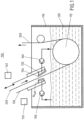
- the figure shows the device 100 for hot-dip coating a metal strip 200 with a molten metal 120.
- the molten metal 120 is in a container 110.
- the metal strip 200 is guided by a deflection roller 115 deflected inside the container in the molten metal.
- the nozzle 130 Before it enters the metal melt 120, it is passed through a nozzle 130, the nozzle ensuring that the metal strip is guided under a protective gas atmosphere before it enters the melt 120.
- the nozzle 130 has at least one, preferably two or four, overflow chambers 132 which are connected to one another in a fluid-conducting manner. These overflow chambers serve to collect slag residues or impurities from the surface of the molten metal in the vicinity of the metal strip.
- a suction pump 150 is provided for preferably continuously sucking the impurities out of the overflow chamber; this prevents these slag residues or impurities from coming into contact with the freshly coated metal strip and caking there or on the inside of the snout.
- a lifting device 140 is provided in the snout 130 for moving the snout 130 out of the molten metal and for lowering the snout into the molten metal; the directions of travel for the trunk 130 are marked in the figure with a double arrow.
- device 100 in addition to suction pump 150, device 100 also has a delivery pump 160 for supplying melt, preferably from container 110 into the at least one overflow chamber 132, in particular when the bath-side end of the nozzle is no longer immersed in molten metal 120 . Due to the preferably simultaneous operation of the feed pump 160 and the suction pump 150, it is possible according to the invention, even if the nozzle has been moved out of the melt, to maintain continuous flushing in the overflow chamber 132 in the form of a continuous melt flow and in this way to ensure continuous cleaning of the overflow chamber and to prevent the suction pump from running dry.
- the snout according to the invention can not only be raised and lowered but also pivoted. This applies in particular to the end piece on the bathroom side of the proboscis with the overflow chamber 132; however, other elements of the trunk can also be pivotable.
- the molten metal is, for example, liquid zinc.
- the device 100 according to the invention can also have a level controller 170 for controlling the level of the melt 120 in the overflow chamber 132 even when the nozzle 130 is moved out of the melt 120.
- the controller is designed to set the level of the melt in the overflow chamber 132 to a predetermined target Level N is to be adjusted by suitably varying the output of suction pump 150 and/or delivery pump 160 .
- the target level of the melt in the overflow chamber is below an overflow edge 134 of the overflow chamber 132.
Landscapes
- Chemical & Material Sciences (AREA)
- Engineering & Computer Science (AREA)
- Mechanical Engineering (AREA)
- Chemical Kinetics & Catalysis (AREA)
- Materials Engineering (AREA)
- Metallurgy (AREA)
- Organic Chemistry (AREA)
- Coating With Molten Metal (AREA)
Description
- Die Erfindung betrifft ein Verfahren zum Spülen einer Überlaufkammer an dem badseitigen Ende eines Rüssels einer Vorrichtung zum Schmelztauchbeschichten eines Metallbandes mit einer Metallschmelze. Darüber hinaus betrifft die Erfindung die besagte Vorrichtung zum Schmelztauchbeschichten mit den notwendigen Komponenten zum Durchführen des Verfahrens.
- Die
US 2004/052959 A1 offenbart eine Vorrichtung gemäß dem unabhängigen Vorrichtungsanspruch 3 ohne eine Hubeinrichtung für den Rüssel. - Die europäische Patentschrift
EP 2 989 226 B1 , analog zuDE 10 2013 104 267 B3 , offenbart eine Vorrichtung zum kontinuierlichen Schmelztauchbeschichten von Metallband. Diese Vorrichtung umfasst einen Behälter mit einer Metallschmelze zum Durchleiten des Metallbandes sowie einen Rüssel zum Durchleiten des Metallbandes in einer Schutzgasatmosphäre nach seinem Austritt aus der Metallschmelze. Der Rüssel hat an seinem badseitigen Ende mindestens eine Überlaufkammer zum Aufnehmen von Verunreinigungen von der Oberfläche der Metallschmelze in der Umgebung des frisch beschichteten Metallbandes. Die Vorrichtung weist darüber hinaus eine Hubeinrichtung auf zum Herausfahren des Rüssels aus der Metallschmelze und/oder zum Absenken des Rüssels in die Metallschmelze hinein. Schließlich weist die Vorrichtung eine Saugpumpe auf zum vorzugsweise kontinuierlichen Absaugen der Verunreinigungen aus der Überlaufkammer. Die Überlaufkammer weist darüber hinaus mindestens eine Durchgangsöffnung, auch Spülöffnung genannt auf, durch welche flüssige Metallschmelze aus dem Schmelzbad in die Ablaufkammer fließen kann, welche sodann kontinuierlich mit Hilfe einer Saugpumpe aus der Überlaufkammer abgesaugt wird. Durch die Aufrechthaltung der Spülströmung innerhalb der Überlaufkammer wird auf zuverlässige Weise sichergestellt, dass Schlacke bzw. Verunreinigungen aus dem Rüssel kontinuierlich abgeführt werden, da durch die stete Zufuhr von flüssiger Metallschmelze eine "weiche" Konsistenz der Schlacke aufrecht erhalten bleibt und Ablagerungen, sogenannte Anbackungen, im Rüssel weitestgehend vermieden werden. Ohne eine ausreichende Zufuhr von flüssiger Metallschmelze würden im Rüssel an der Schmelzbadoberfläche schwimmende Schlackenpartikel sich miteinander in Art einer Sinterung verbinden. Der in derEP 2 989 226 B1 offenbarte Rüssel kann ohne Störungen der Schlackenabfuhr geschwenkt und teleskopiert werden. Schließlich verfügt die in der besagten Patentschrift offenbarte Vorrichtung über eine Steuerungs- oder Regelungseinrichtung zum Steuern der Saugpumpe in Abhängigkeit der Höhendifferenz zwischen dem Badspiegel und einer Überlaufkante der Überlaufkammer. - Dem Spülvorgang, wie er aus dem besagten Stand der Technik bekannt ist, haftet der Nachteil an, dass er nur betrieben werden kann, wenn der Rüssel mit seiner Überlaufkammer in die Metallschmelze eingetaucht ist.
- Ausgehend von diesem Stand der Technik liegt der Erfindung die Aufgabe zugrunde, ein erfindungsgemäßes Verfahren zum Spülen einer Überlaufkammer und eine Vorrichtung zum Schmelztauchbeschichten eines Metallbandes zum Durchführen des erfindungsgemäßen Verfahrens dahingehend weiterzubilden, dass der Spülvorgang auch nach einem Herausziehen des Rüssels aus der Schmelze weiter fortgeführt werden kann.
- Diese Aufgabe wird durch das in Patentanspruch 1 beanspruchte Verfahren gelöst. Demnach sieht das Verfahren vor, dass der Rüssel mit der Überlaufkammer zumindest so weit aus dem Schmelzbad herausgefahren wird, dass keine Schmelze über eine Überlaufkante im Inneren des Rüssels in die Überlaufkammer strömen kann und dass der Spülkreislauf auch bei aus der Schmelze herausgefahrenem Rüssel betrieben wird durch Zuführen der Schmelze aus dem Schmelzbad in die Überlaufkammer mit Hilfe einer Förderpumpe.
- Insbesondere bei Beendigung eines Beschichtungsvorganges, beispielsweise im Übergang zwischen zwei zu beschichtenden Metallbändern oder zu Wartungszwecken ist es gelegentlich erforderlich, dass der Rüssel aus dem Schmelzbad herausgefahren werden muss. Bei diesen Situationen bietet das erfindungsgemäße Verfahren den Vorteil, dass der Spülvorgang der Überlaufkammern nicht unterbrochen werden muss, sondern kontinuierlich weiter aufrecht erhalten werden kann, bis der Überlaufrüssel wieder in die Schmelze eingetaucht wird. Die kontinuierliche Fortführung des Spülvorganges der Überlaufkammern auch außerhalb der Schmelze bietet den Vorteil, dass die Kammern auch in dieser Situation weiter gereinigt werden können, um z. B. Anbackungen zu verhindern und dass ein Trockenlaufen der Saugpumpe verhindert wird.
- Gemäß einem ersten Ausführungsbeispiel der Erfindung sieht das erfindungsgemäße Verfahren weiterhin vor, dass das Niveau der Schmelze in der Überlaufkammer auch bei herausgefahrenem Rüssel aus der Schmelze auf ein vorbestimmtes Soll-Niveau geregelt wird durch geeignete Variation der Leistung der Saugpumpe und/oder der Förderpumpe.
- Die oben genannt Aufgabe wird weiterhin durch eine Vorrichtung zum Schmelztauchbeschichten eines Metallbandes mit einer Förderpumpe zum Durchführen des erfindungsgemäßen Verfahrens gelöst. Die Vorteile dieser Vorrichtung entsprechen den oben mit Bezug auf das beanspruchte Verfahren genannten Vorteilen.
- Weitere vorteilhafte Ausgestaltungen der Vorrichtung sind Gegenstand der abhängigen Ansprüche.
- Der Beschreibung ist eine einzige Figur beigefügt, welche die erfindungsgemäße Vorrichtung zum Durchführen des erfindungsgemäßen Verfahrens zeigt.
- Konkret zeigt die Figur die Vorrichtung 100 zum Schmelztauchbeschichten eines Metallbandes 200 mit einer Metallschmelze 120. Die Metallschmelze 120 befindet sich in einem Behälter 110. Das Metallband 200 wird über eine Umlenkrolle 115 im Inneren des Behälters in der Metallschmelze umgelenkt. Es wird vor seinem Eintritt in die Metallschmelze 120 durch einen Rüssel 130 geleitet, wobei der Rüssel gewährleistet, dass das Metallband vor seinem Eintritt in die Schmelze 120 unter einer Schutzgasatmosphäre geführt wird. Der Rüssel 130 weist an seinem badseitigen Ende mindestens eine, vorzugsweise zwei oder vier miteinander fluidleitend verbundene Überlaufkammern 132 auf. Diese Überlaufkammern dienen zum Aufnehmen von Schlackenresten oder Verunreinigungen von der Oberfläche von der Metallschmelze in der Umgebung des Metallbandes. Es ist eine Saugpumpe 150 vorgesehen zum vorzugsweise kontinuierlichen Absaugen der Verunreinigungen aus der Überlaufkammer; auf diese Weise wird verhindert, dass diese Schlackenreste oder Verunreinigungen mit dem frisch beschichteten Metallband in Kontakt geraten und dort oder an der Innenseite des Rüssels anbacken. Darüber hinaus ist im Rüssel 130 eine Hubeinrichtung 140 vorgesehen zum Herausfahren des Rüssels 130 aus der Metallschmelze und zum Absenken des Rüssels in die Metallschmelze; die Verfahrrichtungen für den Rüssel 130 sind in der Figur mit einem Doppelpfeil gekennzeichnet.
- Erfindungsgemäß weist die Vorrichtung 100 neben der der Saugpumpe 150 auch eine Förderpumpe 160 auf zum Zuführen von Schmelze, vorzugsweise aus dem Behälter 110 in die mindestens eine Überlaufkammer 132, insbesondere auch dann, wenn das badseitige Ende des Rüssels nicht mehr in die Metallschmelze 120 eingetaucht ist. Durch den vorzugsweise gleichzeitigen Betrieb der Förderpumpe 160 und der Absaugpumpe 150 ist es erfindungsgemäß möglich, auch wenn der Rüssel aus der Schmelze herausgefahren ist, in der Überlaufkammer 132 eine kontinuierliche Spülung in Form eines kontinuierlichen Schmelzenstromes aufrechtzuerhalten und auf diese Weise eine kontinuierliche Reinigung der Überlaufkammer sicherzustellen sowie ein Trockenlaufen der Saugpumpe zu verhindern.
- Der erfindungsgemäße Rüssel ist nicht nur heb- und senkbar, sondern auch schwenkbar ausgebildet. Das gilt insbesondere für das badseitige Endstück des Rüssels mit der Überlaufkammer 132; es können jedoch auch andere Elemente des Rüssels schwenkbar ausgebildet sein.
- Bei der Metallschmelze handelt es sich beispielsweise um flüssiges Zink. Schließlich kann die erfindungsgemäße Vorrichtung 100 auch eine Niveauregelung 170 aufweisen zum Regeln des Niveaus der Schmelze 120 in der Überlaufkammer 132 auch bei herausgefahrenem Rüssel 130 aus der Schmelze 120. Die Regelung ist ausgebildet, den Pegel der Schmelze in der Überlaufkammer 132 auf ein vorbestimmtes Soll-Niveau Nsoll durch geeignete Variation der Leistung der Saugpumpe 150 und/oder der Förderpumpe 160 einzuregeln. Das Soll-Niveau der Schmelze in der Überlaufkammer liegt unterhalb einer Überlaufkante 134 der Überlaufkammer 132.
-
- 100
- Vorrichtung
- 110
- Behälter
- 115
- Umlenkrolle
- 120
- Metallschmelze
- 130
- Rüssel
- 132
- Überlaufkammer
- 134
- Überlaufkante
- 140
- Hubeinrichtung
- 150
- Saugpumpe
- 160
- Förderpumpe
- 170
- Niveauregelung
- 200
- Metallband
- NSoll
- Soll-Niveau
Claims (7)
- Verfahren zum Spülen einer Überlaufkammer (132) an dem badseitigen Ende eines Rüssels (130) einer Vorrichtung (100) zum Schmelztauchbeschichten eines Metallbandes (200), wobei der Rüssel dient zum Führen des Metallbandes in einer Schutzgasatmosphäre vor Beschichtung des Metallbandes (200) mit einer Metallschmelze (120), aufweisend folgende Schritte:Durchführen eines Spülkreislaufs in der Überlaufkammer (132) durch Zuführen der Metallschmelze (120) aus einem Schmelzbad in die Überlaufkammer (132) einerseits; und gleichzeitiges Abpumpen der Schmelze (120) aus der Überlaufkammer in das Schmelzbad mit Hilfe einer Saugpumpe (150) anderseits;dadurch gekennzeichnet,dass der Rüssel (130) mit der Überlaufkammer (132) zumindest soweit aus dem Schmelzbad herausgefahren wird, dass keine Schmelze über eine Überlaufkante (134) im Innern des Rüssels (130) in die Überlaufkammer strömen kann; unddass der Spülkreislauf auch bei aus der Schmelze herausgefahrenem Rüssel betrieben wird durch Zuführen der Schmelze aus dem Schmelzbad in die Überlaufkammer (132) mit Hilfe einer Förderpumpe (160).
- Verfahren nach Anspruch 1,
dadurch gekennzeichnet,
dass das Niveau der Schmelze (120) in der Überlaufkammer (132) auch bei herausgefahrenem Rüssel (130) auf ein vorbestimmtes Soll-Niveau (NSoll) geregelt wird durch geeignete Variation der Leistung der Saugpumpe (150) und/oder der Förderpumpe (160). - Vorrichtung (100) zum Schmelztauchbeschichten eines Metallbandes (200) mit einer flüssigen Metallschmelze (120), aufweisend:einen Behälter (110) mit der Metallschmelze (120) zum Durchleiten des Metallbandes (200);einen Rüssel (130) zum Durchleiten des Metallbandes in einer Schutzgasatmosphäre vor seinem Eintritt in die Metallschmelze (120), wobei der Rüssel (130) an seinem badseitigen Ende mindestens eine Überlaufkammer (132) aufweist zum Aufnehmen von Verunreinigungen von der Oberfläche der Metallschmelze in der Umgebung des Metallbandes (200);eine Hubeinrichtung (140) zum Herausfahren des Rüssels (130) aus der Metallschmelze und zum Absenken des Rüssels in die Metallschmelze; undeine Saugpumpe (150) zum -vorzugsweise kontinuierlichen - Absaugen der Verunreinigungen aus der Überlaufkammer;gekennzeichnet durcheine Förderpumpe (160) zum Zuführen der Metallschmelze (120) in die Überlaufkammer (132).
- Vorrichtung (100) nach Anspruch 3,
dadurch gekennzeichnet,
dass an dem badseitigen Ende des Rüssels (130) eine Mehrzahl von Überlaufkammern (132) vorgesehen ist, welche in Form von miteinander kommunizierenden Röhren fluidleitend miteinander verbunden sind. - Vorrichtung (100) nach Anspruch 3 oder 4,
dadurch gekennzeichnet,
dass die Überlaufkammer (130) fest an dem Rüssel angeordnet ist. - Vorrichtung nach einem der Ansprüche 3 bis 5,
dadurch gekennzeichnet,
dass zumindest der Endabschnitt des Rüssels (130) mit der Überlaufkammer (132) schwenkbar ausgebildet ist. - Vorrichtung nach einem der Ansprüche 3 bis 6,
gekennzeichnet durch
eine Niveauregelung (170) zum Regeln des Niveaus der Schmelze (120) in der Überlaufkammer (132) während des Spülvorganges auch bei herausgefahrenem Rüssel (130) auf ein vorbestimmtes Soll-Niveau (Nson) durch geeignete Variation der Leistung der Saugpumpe (150) und/oder der Förderpumpe (160).
Applications Claiming Priority (2)
| Application Number | Priority Date | Filing Date | Title |
|---|---|---|---|
| DE102019206609.7A DE102019206609A1 (de) | 2019-05-08 | 2019-05-08 | Verfahren und Vorrichtung zum Spülen einer Überlaufkammer an dem badseitigen Ende eines Rüssels einer Vorrichtung zum Schmelztauchbeschichten |
| PCT/EP2019/069811 WO2020224792A1 (de) | 2019-05-08 | 2019-07-23 | Verfahren und vorrichtung zum spülen einer überlaufkammer an dem badseitigen ende eines rüssels einer vorrichtung zum schmelztauchbeschichten |
Publications (2)
| Publication Number | Publication Date |
|---|---|
| EP3966359A1 EP3966359A1 (de) | 2022-03-16 |
| EP3966359B1 true EP3966359B1 (de) | 2023-03-29 |
Family
ID=72943013
Family Applications (1)
| Application Number | Title | Priority Date | Filing Date |
|---|---|---|---|
| EP19750072.1A Active EP3966359B1 (de) | 2019-05-08 | 2019-07-23 | Verfahren und vorrichtung zum spülen einer überlaufkammer an dem badseitigen ende eines rüssels einer vorrichtung zum schmelztauchbeschichten |
Country Status (7)
| Country | Link |
|---|---|
| US (1) | US11850634B2 (de) |
| EP (1) | EP3966359B1 (de) |
| KR (1) | KR20220002629A (de) |
| CN (1) | CN113966407B (de) |
| DE (1) | DE102019206609A1 (de) |
| PL (1) | PL3966359T3 (de) |
| WO (1) | WO2020224792A1 (de) |
Families Citing this family (5)
| Publication number | Priority date | Publication date | Assignee | Title |
|---|---|---|---|---|
| WO2021048593A1 (en) * | 2019-09-10 | 2021-03-18 | Arcelormittal | Moveable overflow for continuous hot-dip coating equipments |
| CN113637934B (zh) * | 2021-07-22 | 2023-06-27 | 武汉钢铁有限公司 | 一种用于环形溢流炉鼻子制造的辅助装置及方法 |
| CN114807802B (zh) * | 2022-04-24 | 2023-04-07 | 苏州市华盛源机电有限公司 | 基于合金镀液的大功率电机壳表面高效加工装置及方法 |
| CN117431485B (zh) * | 2022-07-12 | 2026-05-19 | 宝山钢铁股份有限公司 | 多工作模式的热镀锌组炉鼻子机组及其内部气氛控制方法 |
| CN118600352B (zh) * | 2024-08-08 | 2025-01-03 | 中南大学 | 锌液面电磁驱渣装置及方法 |
Family Cites Families (17)
| Publication number | Priority date | Publication date | Assignee | Title |
|---|---|---|---|---|
| JPS61103587A (ja) * | 1984-10-26 | 1986-05-22 | Osaka Gas Co Ltd | 埋設パイプの内面用ライニング方法 |
| JP2501654B2 (ja) * | 1990-06-28 | 1996-05-29 | 川崎製鉄株式会社 | 連続溶融亜鉛めっき装置 |
| JPH04120258A (ja) * | 1990-09-12 | 1992-04-21 | Kawasaki Steel Corp | 連続溶融亜鉛めっき方法および装置 |
| JPH04120258U (ja) | 1991-04-15 | 1992-10-27 | 三菱重工業株式会社 | 直流高圧放電電極 |
| JPH08269659A (ja) | 1995-03-31 | 1996-10-15 | Nisshin Steel Co Ltd | 連続溶融めっきにおけるスナウト内ドロスの除去方法および装置 |
| RS50049B (sr) * | 2000-11-10 | 2008-11-28 | Sollac, | Uređaj oblaganja sa namakanjem metalne trake |
| FR2816640B1 (fr) * | 2000-11-10 | 2003-10-31 | Lorraine Laminage | Installation de revetement au trempe a chaud et en continu d'une bande metallique |
| JP2002275608A (ja) * | 2001-03-13 | 2002-09-25 | Nippon Steel Corp | 連続焼鈍材と溶融メッキ材の通板切替え方法 |
| JP2003293107A (ja) * | 2002-04-04 | 2003-10-15 | Nippon Steel Corp | 外観性に優れた溶融金属めっき方法およびその装置 |
| JP5609664B2 (ja) | 2011-01-18 | 2014-10-22 | Jfeスチール株式会社 | スナウト内の異物除去装置およびその異物除去方法 |
| KR20130062525A (ko) * | 2011-12-05 | 2013-06-13 | 주식회사 포스코 | 도금액 유지 장치 |
| CN102925839A (zh) * | 2012-10-25 | 2013-02-13 | 常州大学 | 一种连续热浸镀锌铝中高频调幅磁场离心分离锌渣的方法 |
| DE102013104267B3 (de) * | 2013-04-26 | 2014-02-27 | Thyssenkrupp Steel Europe Ag | Vorrichtung zum kontinuierlichen Schmelztauchbeschichten von Metallband |
| DE102014104509A1 (de) * | 2014-03-31 | 2015-10-01 | Thyssenkrupp Ag | Vorrichtung und Verfahren zur Reinigung einer Schmelze und Schmelztauchbeschichtungsanlage |
| DE102016218947A1 (de) | 2016-04-28 | 2017-11-02 | Sms Group Gmbh | Bauteil für eine Schmelztauchbeschichtungsanlage und Verfahren zum Herstellen eines solchen |
| CN107447174A (zh) * | 2016-05-31 | 2017-12-08 | 宝钢新日铁汽车板有限公司 | 一种炉鼻子内的清洁系统和方法 |
| CN108842121A (zh) * | 2018-08-25 | 2018-11-20 | 宝钢湛江钢铁有限公司 | 一种带钢连续热浸镀锌系统 |
-
2019
- 2019-05-08 DE DE102019206609.7A patent/DE102019206609A1/de not_active Withdrawn
- 2019-07-23 WO PCT/EP2019/069811 patent/WO2020224792A1/de not_active Ceased
- 2019-07-23 CN CN201980096150.8A patent/CN113966407B/zh active Active
- 2019-07-23 US US17/609,697 patent/US11850634B2/en active Active
- 2019-07-23 PL PL19750072.1T patent/PL3966359T3/pl unknown
- 2019-07-23 EP EP19750072.1A patent/EP3966359B1/de active Active
- 2019-07-23 KR KR1020217039255A patent/KR20220002629A/ko not_active Ceased
Also Published As
| Publication number | Publication date |
|---|---|
| EP3966359A1 (de) | 2022-03-16 |
| DE102019206609A1 (de) | 2020-11-12 |
| US20220213582A1 (en) | 2022-07-07 |
| PL3966359T3 (pl) | 2023-07-24 |
| WO2020224792A1 (de) | 2020-11-12 |
| CN113966407B (zh) | 2023-10-27 |
| US11850634B2 (en) | 2023-12-26 |
| KR20220002629A (ko) | 2022-01-06 |
| CN113966407A (zh) | 2022-01-21 |
Similar Documents
| Publication | Publication Date | Title |
|---|---|---|
| WO2020224792A1 (de) | Verfahren und vorrichtung zum spülen einer überlaufkammer an dem badseitigen ende eines rüssels einer vorrichtung zum schmelztauchbeschichten | |
| DE2520732C2 (de) | Verfahren und Vorrichtung zur Steuerung der Bewegung einer Saugvorrichtung | |
| DE2455629B2 (de) | Verfahren zum Aufbringen einer Lötmittelschicht auf eine Fläche einer gedruckten Schaltungsplatte oder eines ähnlichen Körpers und Anordnung zur Durchführung des Verfahrens | |
| WO2014173663A1 (de) | Vorrichtung zum kontinuierlichen schmelztauchbeschichten von metallband | |
| DE2417689A1 (de) | Verfahren und anlage zur kontinuierlichen und regelbaren schlammabsaugung aus einem klaerbecken | |
| DE2619342C3 (de) | Wellenlötvorrichtung | |
| DE2843800C2 (de) | Verfahren und Vorrichtung zum Waschen und Kühlen des Bruchkornes von Cottage- Käse, Quark o.dgl. | |
| EP0052270A1 (de) | Vorrichtung zur Reinigung eines Siels mit geschlossenem Kanalquerschnitt von nicht schwebefähigen Ablagerungen | |
| DE102013213718B3 (de) | Vorrichtung zum Anheben und wieder Absetzen einer Pfanne, Anlage mit einer solchen Vorrichtung und Verfahren | |
| DE102011077247A1 (de) | Verfahren und Vorrichtung zum Auftragen von Lot | |
| DE10234010B4 (de) | Vorrichtung und Verfahren zum Entfernen von Bodenschlacke einer Metallschmelze in einem Schmelztiegel insbesondere bei der Schmelztauchbeschichtung von Metallband | |
| DE4413347A1 (de) | Pulverbeschichtungskabine | |
| EP3826779B1 (de) | Walzgerüst und verfahren zum kühlen der oberen arbeitswalze eines walzgerüstes | |
| DE102019111162A1 (de) | Vorrichtung zur Bearbeitung einer Oberfläche mittels Strahlen einer wässrigen Flüssigkeit | |
| DE4010801C2 (de) | Vorrichtung zum Abstreifen von laufendem Bandmaterial | |
| EP0358847A1 (de) | Verfahren zum Abfüllen von empfindlichen Produkten wie z. B. Obst in Kisten mit einem Wasserbehälter und Vorrichtung zur Durchführung des Verfahrens | |
| DE2061266A1 (de) | Einrichtung zur Abfuehrung des abgesetzten Schlamms aus einem Klaerbecken | |
| EP3938118B1 (de) | Reinigungsvorrichtung für airless-farbspritzgeräte und verfahren dazu | |
| DE202019107110U1 (de) | Reinigungsvorrichtung für Airless-Farbspritzgeräte | |
| DE3903319C1 (de) | ||
| DE102016124641A1 (de) | Lötvorrichtung | |
| DE1923689A1 (de) | Einrichtung zum Verzinnen von Kabelenden | |
| DE1957142C (de) | Verfahren zum Beladen eines Lade raums eines Schiffes mit von einer Saug baggervornchtung gefördertem Baggergut, und Saugbaggervorrichtung zum Durchfuhren dieses Verfahrens | |
| EP3382101A2 (de) | Reinigungsvorrichtung und analoges reinigungsverfahren | |
| DE804279C (de) | Beheizte Reinigungsvorrichtung fuer Metallteile |
Legal Events
| Date | Code | Title | Description |
|---|---|---|---|
| STAA | Information on the status of an ep patent application or granted ep patent |
Free format text: STATUS: UNKNOWN |
|
| STAA | Information on the status of an ep patent application or granted ep patent |
Free format text: STATUS: THE INTERNATIONAL PUBLICATION HAS BEEN MADE |
|
| PUAI | Public reference made under article 153(3) epc to a published international application that has entered the european phase |
Free format text: ORIGINAL CODE: 0009012 |
|
| STAA | Information on the status of an ep patent application or granted ep patent |
Free format text: STATUS: REQUEST FOR EXAMINATION WAS MADE |
|
| 17P | Request for examination filed |
Effective date: 20211208 |
|
| AK | Designated contracting states |
Kind code of ref document: A1 Designated state(s): AL AT BE BG CH CY CZ DE DK EE ES FI FR GB GR HR HU IE IS IT LI LT LU LV MC MK MT NL NO PL PT RO RS SE SI SK SM TR |
|
| DAV | Request for validation of the european patent (deleted) | ||
| DAX | Request for extension of the european patent (deleted) | ||
| GRAP | Despatch of communication of intention to grant a patent |
Free format text: ORIGINAL CODE: EPIDOSNIGR1 |
|
| STAA | Information on the status of an ep patent application or granted ep patent |
Free format text: STATUS: GRANT OF PATENT IS INTENDED |
|
| INTG | Intention to grant announced |
Effective date: 20221013 |
|
| GRAS | Grant fee paid |
Free format text: ORIGINAL CODE: EPIDOSNIGR3 |
|
| GRAA | (expected) grant |
Free format text: ORIGINAL CODE: 0009210 |
|
| STAA | Information on the status of an ep patent application or granted ep patent |
Free format text: STATUS: THE PATENT HAS BEEN GRANTED |
|
| AK | Designated contracting states |
Kind code of ref document: B1 Designated state(s): AL AT BE BG CH CY CZ DE DK EE ES FI FR GB GR HR HU IE IS IT LI LT LU LV MC MK MT NL NO PL PT RO RS SE SI SK SM TR |
|
| REG | Reference to a national code |
Ref country code: CH Ref legal event code: EP |
|
| REG | Reference to a national code |
Ref country code: DE Ref legal event code: R096 Ref document number: 502019007356 Country of ref document: DE |
|
| REG | Reference to a national code |
Ref country code: AT Ref legal event code: REF Ref document number: 1556705 Country of ref document: AT Kind code of ref document: T Effective date: 20230415 |
|
| REG | Reference to a national code |
Ref country code: IE Ref legal event code: FG4D Free format text: LANGUAGE OF EP DOCUMENT: GERMAN |
|
| REG | Reference to a national code |
Ref country code: LT Ref legal event code: MG9D |
|
| PG25 | Lapsed in a contracting state [announced via postgrant information from national office to epo] |
Ref country code: RS Free format text: LAPSE BECAUSE OF FAILURE TO SUBMIT A TRANSLATION OF THE DESCRIPTION OR TO PAY THE FEE WITHIN THE PRESCRIBED TIME-LIMIT Effective date: 20230329 Ref country code: NO Free format text: LAPSE BECAUSE OF FAILURE TO SUBMIT A TRANSLATION OF THE DESCRIPTION OR TO PAY THE FEE WITHIN THE PRESCRIBED TIME-LIMIT Effective date: 20230629 Ref country code: LV Free format text: LAPSE BECAUSE OF FAILURE TO SUBMIT A TRANSLATION OF THE DESCRIPTION OR TO PAY THE FEE WITHIN THE PRESCRIBED TIME-LIMIT Effective date: 20230329 Ref country code: LT Free format text: LAPSE BECAUSE OF FAILURE TO SUBMIT A TRANSLATION OF THE DESCRIPTION OR TO PAY THE FEE WITHIN THE PRESCRIBED TIME-LIMIT Effective date: 20230329 Ref country code: HR Free format text: LAPSE BECAUSE OF FAILURE TO SUBMIT A TRANSLATION OF THE DESCRIPTION OR TO PAY THE FEE WITHIN THE PRESCRIBED TIME-LIMIT Effective date: 20230329 |
|
| REG | Reference to a national code |
Ref country code: NL Ref legal event code: MP Effective date: 20230329 |
|
| PG25 | Lapsed in a contracting state [announced via postgrant information from national office to epo] |
Ref country code: SE Free format text: LAPSE BECAUSE OF FAILURE TO SUBMIT A TRANSLATION OF THE DESCRIPTION OR TO PAY THE FEE WITHIN THE PRESCRIBED TIME-LIMIT Effective date: 20230329 Ref country code: NL Free format text: LAPSE BECAUSE OF FAILURE TO SUBMIT A TRANSLATION OF THE DESCRIPTION OR TO PAY THE FEE WITHIN THE PRESCRIBED TIME-LIMIT Effective date: 20230329 Ref country code: GR Free format text: LAPSE BECAUSE OF FAILURE TO SUBMIT A TRANSLATION OF THE DESCRIPTION OR TO PAY THE FEE WITHIN THE PRESCRIBED TIME-LIMIT Effective date: 20230630 Ref country code: FI Free format text: LAPSE BECAUSE OF FAILURE TO SUBMIT A TRANSLATION OF THE DESCRIPTION OR TO PAY THE FEE WITHIN THE PRESCRIBED TIME-LIMIT Effective date: 20230329 |
|
| PG25 | Lapsed in a contracting state [announced via postgrant information from national office to epo] |
Ref country code: SM Free format text: LAPSE BECAUSE OF FAILURE TO SUBMIT A TRANSLATION OF THE DESCRIPTION OR TO PAY THE FEE WITHIN THE PRESCRIBED TIME-LIMIT Effective date: 20230329 Ref country code: RO Free format text: LAPSE BECAUSE OF FAILURE TO SUBMIT A TRANSLATION OF THE DESCRIPTION OR TO PAY THE FEE WITHIN THE PRESCRIBED TIME-LIMIT Effective date: 20230329 Ref country code: PT Free format text: LAPSE BECAUSE OF FAILURE TO SUBMIT A TRANSLATION OF THE DESCRIPTION OR TO PAY THE FEE WITHIN THE PRESCRIBED TIME-LIMIT Effective date: 20230731 Ref country code: ES Free format text: LAPSE BECAUSE OF FAILURE TO SUBMIT A TRANSLATION OF THE DESCRIPTION OR TO PAY THE FEE WITHIN THE PRESCRIBED TIME-LIMIT Effective date: 20230329 Ref country code: EE Free format text: LAPSE BECAUSE OF FAILURE TO SUBMIT A TRANSLATION OF THE DESCRIPTION OR TO PAY THE FEE WITHIN THE PRESCRIBED TIME-LIMIT Effective date: 20230329 |
|
| PG25 | Lapsed in a contracting state [announced via postgrant information from national office to epo] |
Ref country code: SK Free format text: LAPSE BECAUSE OF FAILURE TO SUBMIT A TRANSLATION OF THE DESCRIPTION OR TO PAY THE FEE WITHIN THE PRESCRIBED TIME-LIMIT Effective date: 20230329 Ref country code: IS Free format text: LAPSE BECAUSE OF FAILURE TO SUBMIT A TRANSLATION OF THE DESCRIPTION OR TO PAY THE FEE WITHIN THE PRESCRIBED TIME-LIMIT Effective date: 20230729 |
|
| REG | Reference to a national code |
Ref country code: DE Ref legal event code: R097 Ref document number: 502019007356 Country of ref document: DE |
|
| PG25 | Lapsed in a contracting state [announced via postgrant information from national office to epo] |
Ref country code: DK Free format text: LAPSE BECAUSE OF FAILURE TO SUBMIT A TRANSLATION OF THE DESCRIPTION OR TO PAY THE FEE WITHIN THE PRESCRIBED TIME-LIMIT Effective date: 20230329 Ref country code: CZ Free format text: LAPSE BECAUSE OF FAILURE TO SUBMIT A TRANSLATION OF THE DESCRIPTION OR TO PAY THE FEE WITHIN THE PRESCRIBED TIME-LIMIT Effective date: 20230329 |
|
| PLBE | No opposition filed within time limit |
Free format text: ORIGINAL CODE: 0009261 |
|
| STAA | Information on the status of an ep patent application or granted ep patent |
Free format text: STATUS: NO OPPOSITION FILED WITHIN TIME LIMIT |
|
| PG25 | Lapsed in a contracting state [announced via postgrant information from national office to epo] |
Ref country code: MC Free format text: LAPSE BECAUSE OF FAILURE TO SUBMIT A TRANSLATION OF THE DESCRIPTION OR TO PAY THE FEE WITHIN THE PRESCRIBED TIME-LIMIT Effective date: 20230329 |
|
| PG25 | Lapsed in a contracting state [announced via postgrant information from national office to epo] |
Ref country code: MC Free format text: LAPSE BECAUSE OF FAILURE TO SUBMIT A TRANSLATION OF THE DESCRIPTION OR TO PAY THE FEE WITHIN THE PRESCRIBED TIME-LIMIT Effective date: 20230329 |
|
| REG | Reference to a national code |
Ref country code: CH Ref legal event code: PL |
|
| 26N | No opposition filed |
Effective date: 20240103 |
|
| PG25 | Lapsed in a contracting state [announced via postgrant information from national office to epo] |
Ref country code: LU Free format text: LAPSE BECAUSE OF NON-PAYMENT OF DUE FEES Effective date: 20230723 |
|
| GBPC | Gb: european patent ceased through non-payment of renewal fee |
Effective date: 20230723 |
|
| PG25 | Lapsed in a contracting state [announced via postgrant information from national office to epo] |
Ref country code: LU Free format text: LAPSE BECAUSE OF NON-PAYMENT OF DUE FEES Effective date: 20230723 |
|
| REG | Reference to a national code |
Ref country code: IE Ref legal event code: MM4A |
|
| PG25 | Lapsed in a contracting state [announced via postgrant information from national office to epo] |
Ref country code: CH Free format text: LAPSE BECAUSE OF NON-PAYMENT OF DUE FEES Effective date: 20230731 Ref country code: GB Free format text: LAPSE BECAUSE OF NON-PAYMENT OF DUE FEES Effective date: 20230723 |
|
| PG25 | Lapsed in a contracting state [announced via postgrant information from national office to epo] |
Ref country code: SI Free format text: LAPSE BECAUSE OF FAILURE TO SUBMIT A TRANSLATION OF THE DESCRIPTION OR TO PAY THE FEE WITHIN THE PRESCRIBED TIME-LIMIT Effective date: 20230329 |
|
| PG25 | Lapsed in a contracting state [announced via postgrant information from national office to epo] |
Ref country code: SI Free format text: LAPSE BECAUSE OF FAILURE TO SUBMIT A TRANSLATION OF THE DESCRIPTION OR TO PAY THE FEE WITHIN THE PRESCRIBED TIME-LIMIT Effective date: 20230329 |
|
| PG25 | Lapsed in a contracting state [announced via postgrant information from national office to epo] |
Ref country code: IE Free format text: LAPSE BECAUSE OF NON-PAYMENT OF DUE FEES Effective date: 20230723 |
|
| PG25 | Lapsed in a contracting state [announced via postgrant information from national office to epo] |
Ref country code: IE Free format text: LAPSE BECAUSE OF NON-PAYMENT OF DUE FEES Effective date: 20230723 |
|
| PG25 | Lapsed in a contracting state [announced via postgrant information from national office to epo] |
Ref country code: BG Free format text: LAPSE BECAUSE OF FAILURE TO SUBMIT A TRANSLATION OF THE DESCRIPTION OR TO PAY THE FEE WITHIN THE PRESCRIBED TIME-LIMIT Effective date: 20230329 |
|
| PG25 | Lapsed in a contracting state [announced via postgrant information from national office to epo] |
Ref country code: BG Free format text: LAPSE BECAUSE OF FAILURE TO SUBMIT A TRANSLATION OF THE DESCRIPTION OR TO PAY THE FEE WITHIN THE PRESCRIBED TIME-LIMIT Effective date: 20230329 |
|
| PG25 | Lapsed in a contracting state [announced via postgrant information from national office to epo] |
Ref country code: CY Free format text: LAPSE BECAUSE OF FAILURE TO SUBMIT A TRANSLATION OF THE DESCRIPTION OR TO PAY THE FEE WITHIN THE PRESCRIBED TIME-LIMIT; INVALID AB INITIO Effective date: 20190723 |
|
| PG25 | Lapsed in a contracting state [announced via postgrant information from national office to epo] |
Ref country code: HU Free format text: LAPSE BECAUSE OF FAILURE TO SUBMIT A TRANSLATION OF THE DESCRIPTION OR TO PAY THE FEE WITHIN THE PRESCRIBED TIME-LIMIT; INVALID AB INITIO Effective date: 20190723 |
|
| PGFP | Annual fee paid to national office [announced via postgrant information from national office to epo] |
Ref country code: DE Payment date: 20250722 Year of fee payment: 7 |
|
| PGFP | Annual fee paid to national office [announced via postgrant information from national office to epo] |
Ref country code: IT Payment date: 20250724 Year of fee payment: 7 Ref country code: TR Payment date: 20250716 Year of fee payment: 7 Ref country code: PL Payment date: 20250710 Year of fee payment: 7 |
|
| PGFP | Annual fee paid to national office [announced via postgrant information from national office to epo] |
Ref country code: BE Payment date: 20250721 Year of fee payment: 7 |
|
| PGFP | Annual fee paid to national office [announced via postgrant information from national office to epo] |
Ref country code: FR Payment date: 20250725 Year of fee payment: 7 Ref country code: AT Payment date: 20250722 Year of fee payment: 7 |