EP3960056A1 - Beutelloser bodenstaubsauger - Google Patents
Beutelloser bodenstaubsauger Download PDFInfo
- Publication number
- EP3960056A1 EP3960056A1 EP21185704.0A EP21185704A EP3960056A1 EP 3960056 A1 EP3960056 A1 EP 3960056A1 EP 21185704 A EP21185704 A EP 21185704A EP 3960056 A1 EP3960056 A1 EP 3960056A1
- Authority
- EP
- European Patent Office
- Prior art keywords
- vacuum cleaner
- separator
- wheel axle
- drive unit
- cleaner according
- Prior art date
- Legal status (The legal status is an assumption and is not a legal conclusion. Google has not performed a legal analysis and makes no representation as to the accuracy of the status listed.)
- Granted
Links
Images

Classifications
-
- A—HUMAN NECESSITIES
- A47—FURNITURE; DOMESTIC ARTICLES OR APPLIANCES; COFFEE MILLS; SPICE MILLS; SUCTION CLEANERS IN GENERAL
- A47L—DOMESTIC WASHING OR CLEANING; SUCTION CLEANERS IN GENERAL
- A47L9/00—Details or accessories of suction cleaners, e.g. mechanical means for controlling the suction or for effecting pulsating action; Storing devices specially adapted to suction cleaners or parts thereof; Carrying-vehicles specially adapted for suction cleaners
- A47L9/22—Mountings for motor fan assemblies
-
- A—HUMAN NECESSITIES
- A47—FURNITURE; DOMESTIC ARTICLES OR APPLIANCES; COFFEE MILLS; SPICE MILLS; SUCTION CLEANERS IN GENERAL
- A47L—DOMESTIC WASHING OR CLEANING; SUCTION CLEANERS IN GENERAL
- A47L5/00—Structural features of suction cleaners
- A47L5/12—Structural features of suction cleaners with power-driven air-pumps or air-compressors, e.g. driven by motor vehicle engine vacuum
- A47L5/22—Structural features of suction cleaners with power-driven air-pumps or air-compressors, e.g. driven by motor vehicle engine vacuum with rotary fans
- A47L5/28—Suction cleaners with handles and nozzles fixed on the casings, e.g. wheeled suction cleaners with steering handle
-
- A—HUMAN NECESSITIES
- A47—FURNITURE; DOMESTIC ARTICLES OR APPLIANCES; COFFEE MILLS; SPICE MILLS; SUCTION CLEANERS IN GENERAL
- A47L—DOMESTIC WASHING OR CLEANING; SUCTION CLEANERS IN GENERAL
- A47L5/00—Structural features of suction cleaners
- A47L5/12—Structural features of suction cleaners with power-driven air-pumps or air-compressors, e.g. driven by motor vehicle engine vacuum
- A47L5/22—Structural features of suction cleaners with power-driven air-pumps or air-compressors, e.g. driven by motor vehicle engine vacuum with rotary fans
- A47L5/36—Suction cleaners with hose between nozzle and casing; Suction cleaners for fixing on staircases; Suction cleaners for carrying on the back
- A47L5/362—Suction cleaners with hose between nozzle and casing; Suction cleaners for fixing on staircases; Suction cleaners for carrying on the back of the horizontal type, e.g. canister or sledge type
-
- A—HUMAN NECESSITIES
- A47—FURNITURE; DOMESTIC ARTICLES OR APPLIANCES; COFFEE MILLS; SPICE MILLS; SUCTION CLEANERS IN GENERAL
- A47L—DOMESTIC WASHING OR CLEANING; SUCTION CLEANERS IN GENERAL
- A47L9/00—Details or accessories of suction cleaners, e.g. mechanical means for controlling the suction or for effecting pulsating action; Storing devices specially adapted to suction cleaners or parts thereof; Carrying-vehicles specially adapted for suction cleaners
-
- A—HUMAN NECESSITIES
- A47—FURNITURE; DOMESTIC ARTICLES OR APPLIANCES; COFFEE MILLS; SPICE MILLS; SUCTION CLEANERS IN GENERAL
- A47L—DOMESTIC WASHING OR CLEANING; SUCTION CLEANERS IN GENERAL
- A47L9/00—Details or accessories of suction cleaners, e.g. mechanical means for controlling the suction or for effecting pulsating action; Storing devices specially adapted to suction cleaners or parts thereof; Carrying-vehicles specially adapted for suction cleaners
- A47L9/009—Carrying-vehicles; Arrangements of trollies or wheels; Means for avoiding mechanical obstacles
-
- A—HUMAN NECESSITIES
- A47—FURNITURE; DOMESTIC ARTICLES OR APPLIANCES; COFFEE MILLS; SPICE MILLS; SUCTION CLEANERS IN GENERAL
- A47L—DOMESTIC WASHING OR CLEANING; SUCTION CLEANERS IN GENERAL
- A47L9/00—Details or accessories of suction cleaners, e.g. mechanical means for controlling the suction or for effecting pulsating action; Storing devices specially adapted to suction cleaners or parts thereof; Carrying-vehicles specially adapted for suction cleaners
- A47L9/10—Filters; Dust separators; Dust removal; Automatic exchange of filters
-
- A—HUMAN NECESSITIES
- A47—FURNITURE; DOMESTIC ARTICLES OR APPLIANCES; COFFEE MILLS; SPICE MILLS; SUCTION CLEANERS IN GENERAL
- A47L—DOMESTIC WASHING OR CLEANING; SUCTION CLEANERS IN GENERAL
- A47L9/00—Details or accessories of suction cleaners, e.g. mechanical means for controlling the suction or for effecting pulsating action; Storing devices specially adapted to suction cleaners or parts thereof; Carrying-vehicles specially adapted for suction cleaners
- A47L9/10—Filters; Dust separators; Dust removal; Automatic exchange of filters
- A47L9/12—Dry filters
- A47L9/122—Dry filters flat
-
- A—HUMAN NECESSITIES
- A47—FURNITURE; DOMESTIC ARTICLES OR APPLIANCES; COFFEE MILLS; SPICE MILLS; SUCTION CLEANERS IN GENERAL
- A47L—DOMESTIC WASHING OR CLEANING; SUCTION CLEANERS IN GENERAL
- A47L9/00—Details or accessories of suction cleaners, e.g. mechanical means for controlling the suction or for effecting pulsating action; Storing devices specially adapted to suction cleaners or parts thereof; Carrying-vehicles specially adapted for suction cleaners
- A47L9/10—Filters; Dust separators; Dust removal; Automatic exchange of filters
- A47L9/16—Arrangement or disposition of cyclones or other devices with centrifugal action
-
- A—HUMAN NECESSITIES
- A47—FURNITURE; DOMESTIC ARTICLES OR APPLIANCES; COFFEE MILLS; SPICE MILLS; SUCTION CLEANERS IN GENERAL
- A47L—DOMESTIC WASHING OR CLEANING; SUCTION CLEANERS IN GENERAL
- A47L9/00—Details or accessories of suction cleaners, e.g. mechanical means for controlling the suction or for effecting pulsating action; Storing devices specially adapted to suction cleaners or parts thereof; Carrying-vehicles specially adapted for suction cleaners
- A47L9/24—Hoses or pipes; Hose or pipe couplings
-
- A—HUMAN NECESSITIES
- A47—FURNITURE; DOMESTIC ARTICLES OR APPLIANCES; COFFEE MILLS; SPICE MILLS; SUCTION CLEANERS IN GENERAL
- A47L—DOMESTIC WASHING OR CLEANING; SUCTION CLEANERS IN GENERAL
- A47L9/00—Details or accessories of suction cleaners, e.g. mechanical means for controlling the suction or for effecting pulsating action; Storing devices specially adapted to suction cleaners or parts thereof; Carrying-vehicles specially adapted for suction cleaners
- A47L9/26—Incorporation of winding devices for electric cables
-
- A—HUMAN NECESSITIES
- A47—FURNITURE; DOMESTIC ARTICLES OR APPLIANCES; COFFEE MILLS; SPICE MILLS; SUCTION CLEANERS IN GENERAL
- A47L—DOMESTIC WASHING OR CLEANING; SUCTION CLEANERS IN GENERAL
- A47L9/00—Details or accessories of suction cleaners, e.g. mechanical means for controlling the suction or for effecting pulsating action; Storing devices specially adapted to suction cleaners or parts thereof; Carrying-vehicles specially adapted for suction cleaners
- A47L9/32—Handles
- A47L9/327—Handles for suction cleaners with hose between nozzle and casing
Definitions
- the invention relates to a bagless canister vacuum cleaner, which is also referred to simply as a vacuum cleaner below.
- a vacuum cleaner usually has a housing which has a suction inlet for sucking in suction air in a front region, a separator, a drive unit, a cable drum and two wheels.
- the suction inlet is equipped with a suction nozzle that may be fitted.
- a bagless vacuum cleaner is generally a cyclone vacuum cleaner in which turbulence and any turbulence are generated in an incoming air flow, as a result of which the suction material, such as dust particles, is pressed in a predetermined direction and separated due to centrifugal force.
- bagless means that the suction material in the vacuum cleaner is collected directly in the separator without a bag or similar exchangeable filter medium for receiving suction material being arranged in it, so that the user has to empty the suction material from the separator does not remove a bag or the like from the separator.
- the canister vacuum cleaner can have one or more filter media that prevent suction material from entering the drive unit.
- position and direction information relate to a working position of the vacuum cleaner.
- the vacuum cleaner in particular the suction hose and any suction nozzle mounted thereon, can have a forward movement direction, also referred to here as the main direction, and a backward movement direction when it is moved back and forth during a suction process.
- the housing of the vacuum cleaner is moved in one direction.
- the position and direction information in this application relates in particular to a working position, with the suction inlet always being arranged in the front area of the vacuum cleaner, with the front area being arranged at the front in the direction of travel and the rear area being arranged at the rear in the direction of travel.
- the drive unit and the cable drum are relatively heavy components and are usually located at the rear of the vacuum cleaner. As a result, the center of gravity of such a vacuum cleaner is also more rearward and generally requires a carrying handle at the front of the vacuum cleaner, resulting in an upright carrying position.
- front area and rear area refer to areas which are defined as front and rear in relation to the direction of travel by a wheel axis running through the two pivot points of the two wheels, the wheel axis being an (imaginary) dividing line between the front and and rear area forms.
- the front area is the area where the suction entrance is located. Because the center of gravity is in the rear area, such a vacuum cleaner can rotate to the left or right by pivoting at the front and “stopping" at the center of gravity at the back, which can lead to swaying when a user pulls the vacuum cleaner behind.
- the invention therefore addresses the problem of providing a bagless floor vacuum cleaner that has improved maneuverability.
- the invention relates to a bagless canister vacuum cleaner with a housing which has a suction inlet for sucking in suction air in a front area, a separator, a drive unit, a cable drum, two wheels and a wheel axle running through the two pivot points of the two wheels, the drive unit and the Cable drums are arranged in a front area in front of the wheel axle and the separator is arranged in a rear area behind the wheel axle, so that there is a focus of the vacuum cleaner in the front area in front of the wheel axle.
- the separator is preferably arranged transversely to the direction of travel in the canister vacuum cleaner with respect to its longitudinal axis. This enables a compact design of the vacuum cleaner and an optimal distribution of the center of gravity.
- Position and direction information refers to the working position and direction of travel of the cylinder vacuum cleaner.
- the separator is located at the rear and the cable drum and drive unit are located at the front, the weight distribution in the vacuum cleaner is optimized. As a result, the center of gravity is in the front area in front of the wheels. This leads to a safe stand of the vacuum cleaner.
- the vacuum cleaner is relatively small, compact and extremely manoeuvrable. At the same time he is powerfully trained.
- the wheel axle can be physically present in the vacuum cleaner and can be realized, for example, by a connecting rod connecting the wheels.
- the wheel axis is preferably an imaginary line; i.e. she is not physically trained.
- the cable reel and the drive unit are preferably arranged next to one another in the front area.
- the cable reel is arranged next to one another on the left in the direction of travel and the drive unit on the right in the direction of travel.
- the drive unit is preferably a fan.
- the cable reel and the drive unit are preferably accommodated in the housing, while the separator has a separator container which is preferably detachably connected to the housing.
- the center of gravity is at a distance from the wheel axis that is less than 10%, preferably less than 5%, more preferably less than 2% of a device length that extends along the front area and the rear area in the direction of travel.
- the center of gravity is the center of mass.
- the center of gravity preferably shifts by less than 10%, preferably less than 5%, more preferably less than 2% along the device length compared to the case of an empty separator arranged in the canister vacuum cleaner. This also leads to a secure stand of the vacuum cleaner in the event of maintenance, when the separator has been removed from the vacuum cleaner.
- the separator is removed from the vacuum cleaner by detaching it from the housing.
- Maintenance means that the separator is removed from the vacuum cleaner for emptying and the vacuum cleaner stands briefly on a surface without the separator. Because there is little or no change in the center of gravity when the separator is removed, the vacuum cleaner stands firmly on the ground with and without the separator.
- the center of gravity of the vacuum cleaner is designed in such a way that, even when standing on a surface with a slope of up to 10°, the vacuum cleaner stands stable and does not tip over, regardless of whether the separator is connected to the housing or removed from it .
- the canister vacuum cleaner also has a skid, which is arranged in the front area in front of the wheel axle in such a way that the center of gravity is behind it. This will continue to ensure a secure footing.
- the skid is preferably arranged and designed in such a way that the vacuum cleaner stands on it and the wheels on the ground during operation and can be moved.
- the floor vacuum cleaner also has a carrying handle, which is arranged on an upper side of the floor vacuum cleaner.
- a carrying handle which is arranged on an upper side of the floor vacuum cleaner. This makes the vacuum cleaner easy to carry. To carry the vacuum cleaner, it does not have to be tilted first, but can be lifted and carried directly into the operating position using the carrying handle or handle on the top, which is easy on the back.
- the carrying handle is preferably formed on the housing.
- the vacuum cleaner further comprises a separator carrying handle which is arranged on the separator and by means of which the separator can be carried when it is removed from the housing.
- the separator carrying handle is preferably also located on the top of the vacuum cleaner.
- the floor vacuum cleaner preferably also has one or more operating elements which are arranged on the top of the floor vacuum cleaner. As a result, they are arranged so that they are easily accessible for the user.
- the canister vacuum cleaner also has a support wheel which is arranged and designed in such a way that it only touches a surface on which the canister vacuum cleaner is arranged in the working position if the skid is at least 1 mm, preferably 2 mm, from the ground , more preferably 3 mm apart. This prevents the vacuum cleaner from being vulnerable when pulling with a trailing edge on the ground and "scratching" it. This further prevents damage to the substrate.
- the support roller generally has no contact with the floor and only touches the floor when the vacuum cleaner is or is slightly raised at the front.
- the support wheel preferably has ribs which are arranged in such a way that they protect the support wheel from collisions when the vacuum cleaner moves in the direction of travel.
- the ribs serve to protect the support roller in the direction of travel, so that it is not damaged, especially when driving over thresholds.
- the support roller preferably has ribs pointing away in the direction of travel.
- the wheels of the vacuum cleaner are preferably made relatively large.
- the wheels In a side view of the vacuum cleaner along its length along the front area and the rear area and a plan view of a diameter of the wheels, the wheels preferably each have a diameter that is greater than half the maximum height of the housing, more preferably greater than three quarters of the maximum height of the housing is, but is smaller than the maximum height.
- the maximum height of the housing represents a dimension in the working position of the vacuum cleaner, which, starting from the base on which the vacuum cleaner is standing, extends perpendicularly from the base and furthest away from the base.
- the wheels have an inclination in a range of 1 to 7°, preferably 2 to 6°.
- the vacuum cleaner achieves better lateral guidance.
- this tendency is referred to as camber or wheel camber.
- the camber is an angle between the center plane of the wheel and a perpendicular to the ground at the point of contact of the wheel.
- the suction inlet is preferably arranged in the front area in a lower area of the canister vacuum cleaner.
- the suction inlet is preferably formed below half the maximum height of the housing in the front area of the housing.
- a suction flow generated by the power unit during operation has the following air path: the suction flow flows from the suction inlet through a duct to an upper region of the separator, then through the separator, then through the power unit, then through an engine compartment deflected back and then flows through an exhaust air filter.
- the channel between the suction inlet and the separator is preferably S-shaped. The air is preferentially blown through the power-plant, then into the engine compartment, redirected back and blown forward to reduce power-plant noise.
- a bellows seal is preferably arranged between the channel and the separator. As a result, a relatively large amount of play is realized at this point.
- a replaceable seal is preferably arranged between the separator and a part of the housing containing the drive unit.
- the seal is preferably arranged on the housing side.
- the exhaust air filter is preferably guided over a sliding link.
- the exhaust air filter preferably has an exhaust air grille which has a large number of nozzles, each with a predetermined blow-out direction. When it leaves the vacuum cleaner, the air is blown through the exhaust air grille, which contains a nozzle in each honeycomb that gives the air a targeted blow-out direction to prevent the air flow from blowing dirt particles in front of the vacuum cleaner beforehand.
- the vacuum cleaner preferably has a cable duct for the cable drum.
- the separator preferably has a cyclone cylinder, ie a cylinder in which the cyclone is generated during operation.
- the cyclone cylinder is preferably arranged transversely to the direction of travel.
- the vacuum cleaner has a spherical design. This means that it does not have an elongated shape when viewed from the side, but rather a spherical shape. This makes it compact.
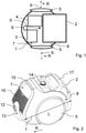
- the vacuum cleaner has a housing 1, which has a suction inlet (not shown) in a front region 7 for sucking in suction air.
- the vacuum cleaner also has a separator 2, a drive unit 3, a cable drum 4, two wheels 5 and a wheel axle 6 running through the two pivot points of the two wheels 5.
- the drive unit 3 and the cable drum 4 are arranged in the front area 7 in front of the wheel axle 6 , while the separator 2 is arranged in a rear area 8 behind the wheel axle 6 . is, so that a focus S of the vacuum cleaner is in the front area 7 in front of the wheel axle 6 .
- the wheel axle 6, which represents an imaginary line and is therefore shown in broken lines, separates the front area 7, which lies in front of the wheel axle 6, and the rear area 8, which lies behind the wheel axle 6.
- the vacuum cleaner is spherical. During operation, the vacuum cleaner is moved in a travel direction R.
- the front area 7 is at the front in the direction of travel R, while the rear area 8 is at the rear in the direction of travel R.
- the cable drum 4 and the drive unit are arranged side by side.
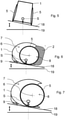
- the vacuum cleaner has the suction inlet 12 which is arranged in the front area 7 in a lower area 13 of the vacuum cleaner.
- An exhaust air grille 15 is arranged above the suction inlet 12 .
- the vacuum cleaner On its upper side, the vacuum cleaner has a carrying handle 10 for carrying the vacuum cleaner, which is arranged and formed on the housing 1 .
- the vacuum cleaner has on its upper side a separator carrying handle 17 which is arranged on the separator 2 and by means of which the separator 2 can be carried separately from the housing 1, ie when the separator 2 is removed from the housing 1.
- the Vacuum cleaner a control 14 on its top.
- the vacuum cleaner has a length L along the front area 7 and the rear area 8 .
- FIG 3 shows a cross-sectional view of the in 1 shown vacuum cleaner.
- a suction hose 16 is mounted on the suction inlet (not shown).
- the vacuum cleaner has a skid 9 which is arranged in the front area 7 in such a way that the center of gravity (not shown) lies behind it. Furthermore, the vacuum cleaner has a support roller 11 in the rear area 8 .
- a suction flow generated by the power pack 3 has the following air path:
- the suction flow flows from the suction inlet (not shown) through a duct (not shown) to an upper region of the separator 2, then through the separator 2, then through the power pack 3, then through an engine compartment (not shown), is redirected back and then flows through the exhaust filter 15.
- FIG. 4 shows another part cross-sectional part plan view of the in 1 shown vacuum cleaner.
- the cable reel 4 and the drive unit 3 are arranged next to one another in the front area 7 .
- figure 5 shows a front view of the in 1 shown vacuum cleaner.
- the vacuum cleaner is arranged on an inclined base 18 which has an incline of 10°, indicated by a double arrow, to an imaginary flat base 19 .
- the center of gravity S lies in the middle between the two wheels 5, which have an inclination (not shown), ie a wheel camber of 4°.
- the vacuum cleaner is stable on the ground 18.
- FIG. 6 shows a side view of the in figure 5 shown vacuum cleaner.
- the vacuum cleaner is arranged on the sloping base 18 which has the gradient of 10° to the imaginary level base 19 indicated by the double arrow.
- the housing 1 and the separator 2 are connected to each other.
- the center of gravity S is in the front area 7 in front of the wheel axle 6.
- the vacuum cleaner is stable on the ground 18.
- FIG. 7 shows a side view of the in 6 shown vacuum cleaner with removed separator container.
- the inside 7 shown vacuum cleaner corresponds to the in 6 shown vacuum cleaner with the difference that the separator is removed from the housing 1.
- the center of gravity S is in the front area in front of the wheel axle 6. Compared to the center of gravity of the in 6 vacuum cleaner shown, the center of gravity S has not shifted or has shifted only slightly.
- the vacuum cleaner is stable on the ground 18.
Landscapes
- Engineering & Computer Science (AREA)
- Mechanical Engineering (AREA)
- Electric Suction Cleaners (AREA)
Abstract
Description
- Die Erfindung betrifft einen beutellosen Bodenstaubsauger, der nachstehend auch einfach als Staubsauger bezeichnet wird. Solch ein Staubsauger weist üblicherweise ein Gehäuse, welches in einem Vorderbereich einen Saugeingang zum Einsaugen von Saugluft aufweist, einen Abscheider, ein Antriebsaggregat, eine Kabeltrommel und zwei Räder auf. Der Saugeingang ist bei Betrieb mit einem Saugschlauch mit ggf. montierter Saugdüse versehen.
- Ein beutelloser Staubsauger ist im Allgemeinen ein Zyklon-Staubsauger, bei dem in einem eintretenden Luftstrom Wirbel und etwaige Verwirbelungen erzeugt werden, wodurch das Sauggut wie z.B. Staubteilchen aufgrund von Fliehkraft in eine vorbestimmte Richtung gedrückt und abgeschieden wird. Unter dem Ausdruck "beutellos" ist zu verstehen, dass das Sauggut in dem Staubsauger direkt im Abscheider gesammelt wird, ohne dass in diesem ein Beutel oder ein ähnliches Wechselfiltermedium zur Aufnahme von Sauggut angeordnet ist, so dass der Nutzer zur Entleerung des Saugguts aus dem Abscheider keinen Beutel oder dgl. aus dem Abscheider entnimmt. Der Bodenstaubsauger kann aber ein oder mehrere Filtermedien aufweisen, die verhindern, dass Sauggut in das Antriebsaggregat gelangt.
- Der klassische Aufbau solch eines Bodenstaubsaugers ist aus Sicht der Luftströmung, die bei Betrieb mittels des Antriebaggregats erzeugt wird, eher linear. Damit ist gemeint, dass im Vorderbereich die Luft angesaugt, zur Reinigung durch den Abscheider geführt, dann durch das Antriebsaggregat geleitet und anschließend nach hinten oder hinten oben ausgeblasen wird. Dies führt zu einer länglichen Bauform des Staubsaugers. Positions- und Richtungsangaben beziehen sich in dieser Anmeldung auf eine Arbeitsposition des Staubsaugers. Bei der betriebsgemäßen Arbeitsposition kann der Staubsauger insbesondere der Saugschlauch und ggf. daran montierte Saugdüse eine Vorwärtsbewegungsrichtung, hier auch als Hauptrichtung bezeichnet, und eine Rückwärtsbewegungsrichtung aufweisen, wenn er während eines Saugvorgangs hin und her bewegt wird. Das Gehäuse des Staubsaugers wird dabei in eine Fahrtrichtung bewegt. Die Positions- und Richtungsangaben beziehen sich in dieser Anmeldung insbesondere auf eine Arbeitsposition, wobei der Saugeingang stets im Vorderbereich des Staubsaugers angeordnet ist, wobei der Vorderbereich in Fahrtrichtung vorne und der Hinterbereich in Fahrtrichtung hinten angeordnet ist.
- Das Antriebsaggregat und die Kabeltrommel sind relativ schwere Komponenten und üblicherweise im Hinterbereich des Staubsaugers angeordnet. Dadurch liegt der Schwerpunkt solch eines Staubsaugers auch eher hinten und erfordert im Allgemeinen einen Tragegriff im Vorderbereich des Staubsaugers, was zu einer aufrechten Trage-Position führt.
- Die Begriffe "Vorderbereich" und "Hinterbereich" beziehen sich auf Bereiche, die durch eine durch die zwei Drehpunkte der beiden Räder verlaufende Radachse als vorne und hinten in Bezug auf die Fahrtrichtung definiert sind, wobei die Radachse eine (gedachte) Trennlinie zwischen dem Vorder- und Hinterbereich bildet. Der Vorderbereich ist der Bereich, in dem der Saugeingang liegt. Durch den im Hinterbereich liegenden Schwerpunkt kann solch ein Staubsauger eine Links- oder Rechtsdrehung ausführen, in dem er vorne schwenkt und hinten beim Schwerpunkt "stehenbleibt", was zum Schlingern führen kann, wenn ein Nutzer den Staubsauger hinterherzieht.
- Der Erfindung stellt sich somit das Problem, einen beutellosen Bodenstaubsauger bereitzustellen, der eine verbesserte Manövrierfähigkeit aufweist.
- Erfindungsgemäß wird dieses Problem durch einen beutellosen Bodenstaubsauger mit den Merkmalen des Patentanspruchs 1 gelöst. Vorteilhafte Ausgestaltungen und Weiterbildungen der Erfindung ergeben sich aus den nachfolgenden Unteransprüchen.
- Die mit der Erfindung erreichbaren Vorteile bestehen neben der Kompaktheit und hervorragenden Manövrierfähigkeit des Staubsaugers darin, dass der Staubsauger relativ klein ist und damit wenig Stauraum benötigt.
- Die Erfindung betrifft einen beutellosen Bodenstaubsauger mit einem Gehäuse, welches in einem Vorderbereich einen Saugeingang zum Einsaugen von Saugluft aufweist, einem Abscheider, einem Antriebsaggregat, einer Kabeltrommel, zwei Rädern und einer durch die zwei Drehpunkte der beiden Räder verlaufenden Radachse, wobei das Antriebsaggregat und die Kabeltrommel in einem Vorderbereich vor der Radachse angeordnet sind und der Abscheider in einem Hinterbereich hinter der Radachse angeordnet ist, so dass sich ein Schwerpunkt des Bodenstaubsaugers im Vorderbereich vor der Radachse befindet. Bevorzugt ist der Abscheider dabei in Bezug auf seine Längsachse quer zur Fahrtrichtung im Bodenstaubsauger angeordnet. Dies ermöglicht eine kompakte Bauform des Staubsaugers und eine optimale Schwerpunktverteilung. Positions- und Richtungsangaben beziehen sich auf die Arbeitsposition und Fahrtrichtung des Bodenstaubsaugers.
- Dadurch, dass der Abscheider im Hinterbereich und die Kabeltrommel und das Antriebsaggregat im Vorderbreich angeordnet sind, wird eine optimierte Gewichtsverteilung im Staubsauger erzielt. Dadurch liegt der Schwerpunkt im Vorderbereich vor den Rädern. Dies führt zu einem sicheren Stand des Staubsaugers. Der Staubsauger ist relativ klein, kompakt und hervorragend manövrierfähig. Dabei ist er gleichzeitig kraftvoll ausgebildet.
- Die Radachse kann bei dem Staubsauger körperlich vorhanden sein und beispielsweise durch eine die Räder verbindende Verbindungsstange realisiert sein. Bevorzugt ist die Radachse eine gedachte Linie; d.h., sie ist nicht körperlich ausgebildet.
- Bevorzugt sind die Kabelrolle und das Antriebsaggregat im Vorderbreich nebeneinander angeordnet. Beispielsweise sind die Kabelrolle in Fahrtrichtung links und das Antriebsaggregat in Fahrtrichtung rechts nebeneinander angeordnet. Das Antriebsaggregat ist bevorzugt ein Gebläse. Die Kabelrolle und das Antriebsaggregat sind bevorzugt im Gehäuse untergebracht, während der Abscheider einen Abscheiderbehälter aufweist ist, der mit dem Gehäuse bevorzugt lösbar verbunden ist.
- In einer bevorzugten Ausführungsform weist der Schwerpunkt einen Abstand zu der Radachse auf, der kleiner als 10%, bevorzugt kleiner als 5%, bevorzugter kleiner 2% einer Gerätelänge ist, die sich entlang des Vorderbereichs und des Hinterbereichs in der Fahrtrichtung erstreckt. Dadurch ist die Links- Rechts-Drehung des Staubsaugers nah um den Schwerpunkt. Unter dem Schwerpunkt ist der Massenschwerpunkt zu verstehen.
- Bevorzugt verschiebt sich der Schwerpunkt im Falle eines vom Bodenstaubsauger entnommenen Abscheiders um weniger als 10%, bevorzugt weniger als 5%, bevorzugter weniger als 2% entlang der Gerätelänge gegenüber dem Falle eines in dem Bodenstaubsauger angeordneten leeren Abscheiders. Dies führt auch in einem Wartungsfall, wenn dem Staubsauger der Abscheider entnommen ist, zu einem sicheren Stand des Staubsaugers. Dem Staubsauger wird in einem Wartungsfall der Abscheider durch Lösen von dem Gehäuse entnommen, wobei mit dem Wartungsfall gemeint ist, dass der Abscheider zum Entleeren aus dem Staubsauger entnommen wird und der Staubsauger kurzzeitig ohne den Abscheider auf einem Untergrund steht. Dadurch, dass bei Entnahme des Abscheiders keine oder nur eine geringe Schwerpunktveränderung hervorgerufen wird, steht der Staubsauger mit und ohne Abscheider stabil auf dem Untergrund. Der Schwerpunkt des Staubsaugers ist derart ausgebildet, dass der Staubsauger, auch wenn er auf einem Untergrund mit einer Steigung von bis zu 10° steht, stabil steht und nicht umkippt und dies unabhängig davon, ob der Abscheider mit dem Gehäuse verbunden oder von ihm entnommen ist.
- In einer bevorzugten Ausführungsform weist der Bodenstaubsauger weiterhin eine Gleitkufe auf, die derart im Vorderbereich vor der Radachse angeordnet ist, dass der Schwerpunkt hinter ihr ist. Dadurch wird weiterhin ein sicherer Stand sichergestellt. Die Gleitkufe ist bevorzugt derart angeordnet und ausgebildet, dass der Staubsauger bei Betrieb auf ihr und den Rädern auf dem Untergrund steht und bewegbar ist.
- In einer bevorzugten Ausführungsform weist der Bodenstaubsauger weiterhin einen Tragegriff auf, der an einer Oberseite des Bodenstaubsaugers angeordnet ist. Dadurch ist der Staubsauger gut tragbar. Zum Tragen des Staubsaugers muss dieser nicht erst gekippt werden, sondern kann rückendschonend direkt am obenliegenden Trage- bzw. Handgriff in Betriebsposition angehoben und getragen werden. Der Tragegriff ist bevorzugt am Gehäuse ausgebildet. Bevorzugt weist der Staubsauger weiterhin einen Abscheider-Tragegriff auf, der am Abscheider angeordnet ist und mittels dem der Abscheider tragbar ist, wenn er vom Gehäuse entnommen ist. Der Abscheider-Tragegriff ist bevorzugt ebenfalls an der Oberseite des Staubsaugers angeordnet.
- Bevorzugt weist der Bodenstaubsauger weiterhin ein oder mehrere Bedienelemente auf, die an der Oberseite des Bodenstaubsaugers angeordnet sind. Dadurch sind sie für den Nutzer gut zugänglich angeordnet.
- In einer bevorzugten Ausführungsform weist der Bodenstaubsauger weiterhin ein Unterstützungsrad auf, das derart angeordnet und ausgebildet ist, dass es ausschließlich einen Untergrund, auf dem der Bodenstaubsauger in der Arbeitsposition angeordnet ist, berührt, wenn die Gleitkufe zu dem Untergrund mindestens 1 mm, bevorzugt 2 mm, bevorzugter 3 mm beabstandet ist. Dadurch wird verhindert, dass der Staubsauger anfällig beim Ziehen mit einer Hinterkante auf dem Untergrund wird und diesen "kratzt". Dadurch wird eine Beschädigung des Untergrunds weiterhin verhindert. Die Unterstützungsrolle hat im Allgemeinen keinen Kontakt zum Untergrund und berührt den Untergrund nur, wenn der Staubsauger vorne leicht angehoben ist oder wird.
- Bevorzugt weist das Unterstützungsrad Rippen auf, die derart angeordnet sind, dass sie das Unterstützungsrad vor Zusammenstößen bei Bewegung des Staubsaugers in Fahrtrichtung schützen. Die Rippen dienen für den Eigenschutz der Unterstützungsrolle in die Fahrtrichtung, damit sie insbesondere beim Überfahren von Schwellen nicht beschädigt wird. Die Unterstützungsrolle weist bevorzugt in die Fahrtrichtung abweisende Rippen auf.
- Die Räder des Staubsaugers sind bevorzugt relativ groß ausgebildet. Bei Seitenansicht des Staubsaugers entlang seiner Länge entlang des Vorderbereichs und des Hinterbereichs und Draufsicht auf einen Durchmesser der Räder weisen die Räder bevorzugt jeweils einen Durchmesser auf, der größer als eine halbe Maximal-Höhe des Gehäuses, bevorzugter größer als eine dreiviertel Maximal-Höhe des Gehäuses ist, aber kleiner als die Maximal-Höhe ist. Die Maximal-Höhe des Gehäuses stellt eine Abmessung in der Arbeitsposition des Staubsaugers dar, die sich ausgehend vom Untergrund, auf dem der Staubsauger steht, senkrecht vom Untergrund am weitesten vom Untergrund weg erstreckt. Diese relativ großen Räder begünstigen eine bessere Spurtreue beim Geradeauslauf des Staubsaugers.
- In einer bevorzugten Ausführungsform weisen die Räder eine Neigung in einem Bereich von 1 bis 7°, bevorzugt 2 bis 6° auf. Durch das leichte Neigen der Räder in diesem Bereich wird bei dem Staubsauger eine bessere Seitenführung erzielt. Insbesondere bei Automobilen wird diese Neigung als Sturz oder Radsturz bezeichnet. Unter dem Sturz wird ein Winkel zwischen der Radmittelebene und einer im Aufstandspunkt des Rades errichteten Senkrechten zum Untergrund verstanden.
- Bevorzugt ist der Saugeingang im Vorderbereich in einem unteren Bereich des Bodenstaubsaugers angeordnet ist. Bevorzugt ist der Saugeingang unterhalb der halben Maximal-Höhe des Gehäuses im Vorderbereich im Gehäuse ausgebildet.
- In einer bevorzugten Ausführungsform weist ein bei Betrieb von dem Antriebsaggregat erzeugter Saugstrom folgenden Luftweg auf: Der Saugstrom strömt ausgehend von dem Saugeingang durch einen Kanal zu einem oberen Bereich des Abscheiders, dann durch den Abscheider, anschließend durch das Antriebsaggregat, dann durch einen Motorraum, wird rückumgelenkt und strömt dann durch einen Abluftfilter. Der Kanal zwischen dem Saugeingang und dem Abscheider ist bevorzugt S-förmig ausgebildet. Die Luft wird bevorzugt durch das Antriebsaggregat, dann in den Motorraum geblasen, rückumgelenkt und nach vorne ausgeblasen, um einen Schall des Antriebsaggregats zu reduzieren.
- Bevorzugt ist zwischen dem Kanal und dem Abscheider eine Faltenbalgdichtung angeordnet. Dadurch wird an dieser Stelle relativ viel Spiel realisiert.
- Bevorzugt ist zwischen dem Abscheider und einem das Antriebsaggregat enthaltendem Teil des Gehäuses eine wechselbare Dichtung angeordnet. Bevorzugt ist die Dichtung gehäuseseitig angeordnet.
- Der Abluftfilter ist bevorzugt über eine Gleit-Kulisse geführt. Der Abluftfilter weist bevorzugt ein Abluftgitter auf, das eine Vielzahl von Düsen mit einer jeweils vorbestimmten Ausblasrichtung aufweist. Beim Austritt aus dem Staubsauger wird die Luft durch das Abluftgitter geblasen, welches in jeder Wabe eine Düse enthält, die der Luft eine gezielte Ausblasrichtung gibt, um zu verhindern das der Luftstrom Schmutzpartikel vor dem Staubsauger vorher bläst.
- Der Staubsauger weist bevorzugt einen Kabelkanal für die Kabeltrommel auf.
- Bevorzugt weist der Abscheider einen Zyklon-Zylinder auf, d.h. einen Zylinder, in dem bei Betrieb der Zyklon erzeugt wird. Der Zyklon Zylinders ist bevorzugt quer zur Fahrtrichtung angeordnet.
- Der Staubsauger weist ein kugeliges Design auf. D.h., er weist bei Seitenansicht keine längliche Bauform, sondern eine eher kugelförmige Gestalt auf. Dadurch ist er kompakt.
- Ein Ausführungsbeispiel der Erfindung ist in den Zeichnungen rein schematisch dargestellt und wird nachfolgend näher beschrieben. Es zeigt schematisch und nicht maßstabsgerecht
- Fig. 1
- eine skizzierte Schnittansicht eines erfindungsgemäßen beutellosen Bodenstaubsaugers;
- Fig. 2
- eine perspektivische Seitenansicht des in
Fig. 1 gezeigten Staubsaugers; - Fig. 3
- eine Querschnittsansicht des in
Fig. 1 gezeigten Staubsaugers; - Fig. 4
- eine Teil-Querschnitts-Teil-Draufsicht auf den in
Fig. 1 gezeigten Staubsauger; - Fig. 5
- eine Frontansicht des in
Fig. 1 gezeigten Staubsaugers, - Fig. 6
- eine Seitenansicht des in
Fig. 5 gezeigten Staubsaugers, und - Fig. 7
- eine Seitenansicht des in
Fig. 6 gezeigten Staubsaugers mit entnommenen Abscheidebehälter. -
Fig. 1 zeigt eine skizzierte Schnittansicht eines erfindungsgemäßen beutellosen Bodenstaubsaugers. Der Staubsauger weist ein Gehäuse 1 auf, welches in einem Vorderbereich 7 einen Saugeingang (nicht gezeigt) zum Einsaugen von Saugluft aufweist. Der Staubsauger weist weiterhin einen Abscheider 2, ein Antriebsaggregat 3, eine Kabeltrommel 4, zwei Räder 5 und eine durch die zwei Drehpunkte der beiden Räder 5 verlaufende Radachse 6 auf. Das Antriebsaggregat 3 und die Kabeltrommel 4 sind in dem Vorderbereich 7 vor der Radachse 6 angeordnet, während der Abscheider 2 in einem Hinterbereich 8 hinter der Radachse 6 angeordnet. ist, so dass sich ein Schwerpunkt S des Staubsaugers im Vorderbereich 7 vor der Radachse 6 befindet. Die Radachse 6, die eine gedachte Linie darstellt und daher gestrichelt gezeigt ist, trennt den Vorderbereich 7, der vor der Radachse 6 liegt, und den Hinterbereich 8, der hinter der Radachse 6 liegt. Der Staubsauger ist kugelig ausgebildet. Bei Betrieb wird der Staubsauger in eine Fahrtrichtung R bewegt. Der Vorderbereich 7 liegt in der Fahrtrichtung R vorne, während der Hinterbereich 8 in der Fahrtrichtung R hinten liegt. Die Kabeltrommel 4 und das Antriebsaggregat sind nebeneinander angeordnet. -
Fig. 2 zeigt eine perspektivische Seitenansicht des inFig. 1 gezeigten Staubsaugers. Der Staubsauger weist den Saugeingang 12 auf, der im Vorderbereich 7 in einem unteren Bereich 13 des Staubsaugers angeordnet ist. Oberhalb des Saugeingangs 12 ist ein Abluftgitter 15 angeordnet. Der Staubsauger weist an seiner Oberseite einen Tragegriff 10 zum Tragen des Staubsaugers auf, der am Gehäuse 1 angeordnet und ausgebildet ist. Weiterhin weist der Staubsauger an seiner Oberseite einen Abscheider-Tragegriff 17 auf, der am Abscheider 2 angeordnet ist und mittels dem der Abscheider 2 vom Gehäuse 1 getrennt tragbar ist, d.h., wenn der Abscheider 2 vom Gehäuse 1 entnommen ist. Ferner weist der Staubsauger ein Bedienelement 14 auf seiner Oberseite auf. Der Staubsauger weist eine Länge L entlang des Vorderbereichs 7 und des Hinterbereichs 8 auf. -
Fig. 3 zeigt eine Querschnittsansicht des inFig. 1 gezeigten Staubsaugers. An den Saugeingang (nicht gezeigt) ist ein Saugschlauch 16 montiert. Der Staubsauger weist eine Gleitkufe 9 auf, die im Vorderbereich 7 derart angeordnet ist, dass der Schwerpunkt (nicht gezeigt) hinter ihr liegt. Ferner weist der Staubsauger eine Unterstützungsrolle 11 im Hinterbereich 8 auf. - Bei Betrieb weist ein von dem Antriebsaggregat 3 erzeugter Saugstrom folgenden Luftweg auf: Der Saugstrom strömt ausgehend von dem Saugeingang (nicht gezeigt) durch einen Kanal (nicht gezeigt) zu einem oberen Bereich des Abscheiders 2, dann durch den Abscheider 2, anschließend durch das Antriebsaggregat 3, dann durch einen Motorraum (nicht gezeigt), wird rückumgelenkt und strömt dann durch den Abluftfilter 15.
-
Fig. 4 zeigt eine weitere Teil-Querschnitts-Teil-Draufsicht auf den inFig. 1 gezeigten Staubsauger. Die Kabelrolle 4 und das Antriebsaggregat 3 sind im Vorderbereich 7 nebeneinander angeordnet. -
Fig. 5 zeigt eine Frontansicht des inFig. 1 gezeigten Staubsaugers. Der Staubsauger ist auf einem geneigten Untergrund 18 angeordnet, der eine durch einen Doppelpfeil angedeutet Steigung von 10° zu einem gedachten ebenen Untergrund 19 aufweist. Der Schwerpunkt S liegt mittig zwischen den beiden Rädern 5, die eine Neigung (nicht gezeigt) d.h. einen Radsturz von 4° aufweisen. Der Staubsauger steht stabil auf dem Untergrund 18. -
Fig. 6 zeigt eine Seitenansicht des inFig. 5 gezeigten Staubsaugers. Der Staubsauger ist auf dem geneigten Untergrund 18 angeordnet, der die durch den Doppelpfeil angedeutete Steigung von 10° zu dem gedachten ebenen Untergrund 19 aufweist. Das Gehäuse 1 und der Abscheider 2 sind miteinander verbunden. Der Schwerpunkt S liegt im Vorderbereich 7 vor der Radachse 6. Der Staubsauger steht stabil auf dem Untergrund 18. -
Fig. 7 zeigt eine Seitenansicht des inFig. 6 gezeigten Staubsaugers mit entnommenen Abscheidebehälter. Der inFig. 7 gezeigte Staubsauger entspricht dem inFig. 6 gezeigten Staubsauger mit dem Unterschied, dass der Abscheider vom Gehäuse 1 entnommen ist. Der Schwerpunkt S liegt im Vorderbereich vor der Radachse 6. Im Vergleich zu dem Schwerpunkt des inFig. 6 gezeigten Staubsaugers hat sich der Schwerpunkt S nicht bzw. nur geringfügig verschoben. Der Staubsauger steht stabil auf dem Untergrund 18. -
- L
- Gerätelänge
- R
- Fahrtrichtung
- S
- Schwerpunkt
- 1
- Gehäuse
- 2
- Abscheider
- 3
- Antriebsaggregat
- 4
- Kabeltrommel
- 5
- Rad
- 6
- Radachse
- 7
- Vorderbereich
- 8
- Hinterbereich
- 9
- Gleitkufe
- 10
- Tragegriff
- 11
- Unterstützungsrad
- 12
- Saugeingang
- 13
- unterer Bereich
- 14
- Bedienelement
- 15
- Abluftfilter
- 16
- Saugschlauch
- 17
- Abscheider-Tragegriff
- 18
- Untergrund
- 19
- gedachter ebener Untergrund
Claims (11)
- Beutelloser Bodenstaubsauger mit einem Gehäuse (1), welches in einem Vorderbereich einen Saugeingang (12) zum Einsaugen von Saugluft aufweist, einem Abscheider (2), einem Antriebsaggregat (3), einer Kabeltrommel (4), zwei Rädern (5) und einer durch die zwei Drehpunkte der beiden Räder (5) verlaufenden Radachse (6), wobei das Antriebsaggregat (3) und die Kabeltrommel (4) in einem Vorderbereich (7) vor der Radachse (6) angeordnet sind und der Abscheider (2) in einem Hinterbereich (8) hinter der Radachse (6) angeordnet ist, so dass sich ein Schwerpunkt (S) des Bodenstaubsaugers im Vorderbereich (7) vor der Radachse (6) befindet, wobei sich Positions- und Richtungsangaben auf eine Arbeitsposition des Bodenstaubsaugers beziehen.
- Bodenstaubsauger nach Anspruch 1, dadurch gekennzeichnet, dass der Schwerpunkt (S) einen Abstand zu der Radachse (6) aufweist, der kleiner als 10%, bevorzugt kleiner als 5%, bevorzugter kleiner 2% einer Gerätelänge (L) ist, die sich entlang des Vorderbereichs (7) und des Hinterbereichs (8) in einer Fahrtrichtung (R) erstreckt.
- Bodenstaubsauger nach Anspruch 1 oder 2, dadurch gekennzeichnet, dass sich der Schwerpunkt (S) im Falle eines vom Bodenstaubsauger entnommenen Abscheiders (2) um weniger als 10%, bevorzugt weniger als 5%, bevorzugter weniger als 2% entlang der Gerätelänge (L) gegenüber dem Falle eines in dem Bodenstaubsauger angeordneten leeren Abscheiders (2) verschiebt.
- Bodenstaubsauger nach einem der vorangehenden Ansprüche, gekennzeichnet durch eine Gleitkufe (9), die derart im Vorderbereich (7) vor der Radachse (6) angeordnet ist, dass der Schwerpunkt (S) hinter ihr ist.
- Bodenstaubsauger nach einem der vorangehenden Ansprüche, gekennzeichnet durch einen Tragegriff (10) und/oder ein oder mehrere Bedienelemente (14), der und/oder das oder die an einer Oberseite des Bodenstaubsaugers angeordnet ist oder sind.
- Bodenstaubsauger nach einem der vorangehenden Ansprüche 4 oder 5, gekennzeichnet durch ein Unterstützungsrad (11), das derart angeordnet und ausgebildet ist, dass es ausschließlich einen Untergrund (18), auf dem der Bodenstaubsauger in der Arbeitsposition angeordnet ist, berührt, wenn die Gleitkufe (9) bei Betrieb des Bodenstaubsaugers zu dem Untergrund (18) mindestens 1 mm, bevorzugt 2 mm, bevorzugter 3 mm beabstandet ist.
- Bodenstaubsauger nach Anspruch 6, dadurch gekennzeichnet, dass das Unterstützungsrad (11) Rippen aufweist, die in Fahrtrichtung (R) angeordnet sind.
- Bodenstaubsauger nach einem der vorangehenden Ansprüche, dadurch gekennzeichnet, dass die Räder (5) eine Neigung in einem Bereich von 1 bis 7°, bevorzugt 2 bis 6° aufweisen.
- Bodenstaubsauger nach einem der vorangehenden Ansprüche, dadurch gekennzeichnet, dass der Saugeingang (12) im Vorderbereich (7) in einem unteren Bereich (13) des Bodenstaubsaugers angeordnet ist.
- Bodenstaubsauger nach einem der vorangehenden Ansprüche, dadurch gekennzeichnet, dass ein bei Betrieb von dem Antriebsaggregat (3) erzeugter Saugstrom folgenden Luftweg aufweist: der Saugstrom strömt ausgehend von dem Saugeingang (12) durch einen Kanal zu einem oberen Bereich des Abscheiders (2), dann durch den Abscheider (2), anschließend durch das Antriebsaggregat (3), dann durch einen Motorraum, wird rückumgelenkt und strömt dann durch einen Abluftfilter (15).
- Bodenstaubsauger nach einem der vorangehenden Ansprüche, dadurch gekennzeichnet, dass zwischen dem Kanal und dem Abscheider (2) eine Faltenbalgdichtung angeordnet ist, dass zwischen dem Abscheider (2) und einem das Antriebsaggregat (3) enthaltendem Teil des Gehäuses (1) eine wechselbare Dichtung angeordnet ist und/oder dass der Abluftfilter (15) ein Abluftgitter aufweist, das eine Vielzahl von Düsen mit einer jeweils vorbestimmten Ausblasrichtung aufweist.
Applications Claiming Priority (1)
| Application Number | Priority Date | Filing Date | Title |
|---|---|---|---|
| DE102020122669.1A DE102020122669A1 (de) | 2020-08-31 | 2020-08-31 | Beutelloser Bodenstaubsauger |
Publications (3)
| Publication Number | Publication Date |
|---|---|
| EP3960056A1 true EP3960056A1 (de) | 2022-03-02 |
| EP3960056C0 EP3960056C0 (de) | 2025-02-12 |
| EP3960056B1 EP3960056B1 (de) | 2025-02-12 |
Family
ID=76942830
Family Applications (1)
| Application Number | Title | Priority Date | Filing Date |
|---|---|---|---|
| EP21185704.0A Active EP3960056B1 (de) | 2020-08-31 | 2021-07-15 | Beutelloser bodenstaubsauger |
Country Status (3)
| Country | Link |
|---|---|
| EP (1) | EP3960056B1 (de) |
| CN (1) | CN114098508A (de) |
| DE (1) | DE102020122669A1 (de) |
Citations (5)
| Publication number | Priority date | Publication date | Assignee | Title |
|---|---|---|---|---|
| US20030208875A1 (en) * | 2002-05-08 | 2003-11-13 | Matsushita Electric Industrial Co., Ltd. | Vacuum cleaner |
| WO2008117945A1 (en) * | 2007-03-28 | 2008-10-02 | Chong, Chung-Ook | Vacuum cleaner |
| DE202014002826U1 (de) * | 2013-04-04 | 2014-07-16 | Lg Electronics Inc. | Staubsauger |
| WO2016184482A1 (en) * | 2015-05-15 | 2016-11-24 | Arcelik Anonim Sirketi | A vacuum cleaner |
| US20170332856A1 (en) * | 2016-05-20 | 2017-11-23 | Lg Electronics Inc. | Vacuum cleaner |
Family Cites Families (3)
| Publication number | Priority date | Publication date | Assignee | Title |
|---|---|---|---|---|
| JP2004357999A (ja) * | 2003-06-05 | 2004-12-24 | Sanyo Electric Co Ltd | 電気掃除機 |
| KR101397054B1 (ko) * | 2012-08-31 | 2014-05-20 | 엘지전자 주식회사 | 진공청소기 |
| KR102467328B1 (ko) * | 2016-02-05 | 2022-11-16 | 삼성전자주식회사 | 청소기 |
-
2020
- 2020-08-31 DE DE102020122669.1A patent/DE102020122669A1/de active Pending
-
2021
- 2021-07-15 EP EP21185704.0A patent/EP3960056B1/de active Active
- 2021-08-27 CN CN202111000345.3A patent/CN114098508A/zh active Pending
Patent Citations (5)
| Publication number | Priority date | Publication date | Assignee | Title |
|---|---|---|---|---|
| US20030208875A1 (en) * | 2002-05-08 | 2003-11-13 | Matsushita Electric Industrial Co., Ltd. | Vacuum cleaner |
| WO2008117945A1 (en) * | 2007-03-28 | 2008-10-02 | Chong, Chung-Ook | Vacuum cleaner |
| DE202014002826U1 (de) * | 2013-04-04 | 2014-07-16 | Lg Electronics Inc. | Staubsauger |
| WO2016184482A1 (en) * | 2015-05-15 | 2016-11-24 | Arcelik Anonim Sirketi | A vacuum cleaner |
| US20170332856A1 (en) * | 2016-05-20 | 2017-11-23 | Lg Electronics Inc. | Vacuum cleaner |
Also Published As
| Publication number | Publication date |
|---|---|
| CN114098508A (zh) | 2022-03-01 |
| DE102020122669A1 (de) | 2022-03-03 |
| EP3960056C0 (de) | 2025-02-12 |
| EP3960056B1 (de) | 2025-02-12 |
Similar Documents
| Publication | Publication Date | Title |
|---|---|---|
| EP0288436B1 (de) | Reinigungsfahrzeug zum Säubern von mit einem Hartbelag versehenen Bodenflächen | |
| EP2030550B1 (de) | Upright-Staubsauger | |
| DE19741573C2 (de) | Gebläse zum Bewegen von Abfall | |
| EP3583271B1 (de) | Saugbagger mit schwenkbarer filtereinheit | |
| EP3787455B1 (de) | Saugroboter zum autonomen reinigen eines fahrzeuginnenraums | |
| DE2758827C2 (de) | Auf einem Fahrzeug kippbar befestigter, mehrstufiger Abscheider | |
| EP1162002B1 (de) | Pulversprühbeschichtungskabine | |
| EP2256250B1 (de) | Fahrbare Vorrichtung zum Abtragen von Füllgut von einer Fläche | |
| DE2821027A1 (de) | Kehrmaschine | |
| EP3315666B1 (de) | Vorrichtung und verfahren zur aufnahme von kehrgut | |
| EP0823835B1 (de) | Aufnahmevorrichtung für abfälle | |
| DE10062329C1 (de) | Saug-Kehraggregat | |
| WO1997032464A9 (de) | Aufnahmevorrichtung für abfälle | |
| EP3960056B1 (de) | Beutelloser bodenstaubsauger | |
| DE202005017238U1 (de) | Vorrichtung zur Säuberung, insbesondere zur Sandentfernung, von Grasflächen | |
| CH715503B1 (de) | Selbstfahrende Kehrmaschine. | |
| EP3597828B1 (de) | Strassenfräsmaschine | |
| WO2019149343A1 (de) | Reinigungsgerät | |
| DE102013112978B4 (de) | Zum Sammeln von Grünschnitt eingerichtetes Laubsauggerät | |
| EP3832021B1 (de) | Bodenbearbeitungsmaschine mit staubabsaugung mit wahlweiser filterung der abgesaugten staubbelasteten luft | |
| EP3208383B1 (de) | Handgeführte kehrmaschine | |
| DE3214183A1 (de) | Fahrbare saugfoerderanlage | |
| WO2007017045A1 (de) | Abdeckung einer geöffneten trennstelle in einem luftführsystem eines verbrennungsmotors | |
| DE1774843U (de) | Maschine zum reinigen von strassen, flugplaetzen u. dgl. | |
| DE102019002510A1 (de) | Flächenreinigungsfahrzeug mit einer Fräsvorrichtung zur Sanierung und Reinigung von Verkehrsflächen |
Legal Events
| Date | Code | Title | Description |
|---|---|---|---|
| PUAI | Public reference made under article 153(3) epc to a published international application that has entered the european phase |
Free format text: ORIGINAL CODE: 0009012 |
|
| STAA | Information on the status of an ep patent application or granted ep patent |
Free format text: STATUS: THE APPLICATION HAS BEEN PUBLISHED |
|
| STAA | Information on the status of an ep patent application or granted ep patent |
Free format text: STATUS: REQUEST FOR EXAMINATION WAS MADE |
|
| AK | Designated contracting states |
Kind code of ref document: A1 Designated state(s): AL AT BE BG CH CY CZ DE DK EE ES FI FR GB GR HR HU IE IS IT LI LT LU LV MC MK MT NL NO PL PT RO RS SE SI SK SM TR |
|
| 17P | Request for examination filed |
Effective date: 20220211 |
|
| RBV | Designated contracting states (corrected) |
Designated state(s): AL AT BE BG CH CY CZ DE DK EE ES FI FR GB GR HR HU IE IS IT LI LT LU LV MC MK MT NL NO PL PT RO RS SE SI SK SM TR |
|
| GRAP | Despatch of communication of intention to grant a patent |
Free format text: ORIGINAL CODE: EPIDOSNIGR1 |
|
| STAA | Information on the status of an ep patent application or granted ep patent |
Free format text: STATUS: GRANT OF PATENT IS INTENDED |
|
| RIC1 | Information provided on ipc code assigned before grant |
Ipc: A47L 9/32 20060101ALI20241029BHEP Ipc: A47L 9/22 20060101ALI20241029BHEP Ipc: A47L 9/28 20060101ALI20241029BHEP Ipc: A47L 9/26 20060101ALI20241029BHEP Ipc: A47L 9/16 20060101ALI20241029BHEP Ipc: A47L 9/12 20060101ALI20241029BHEP Ipc: A47L 9/00 20060101ALI20241029BHEP Ipc: A47L 5/36 20060101AFI20241029BHEP |
|
| INTG | Intention to grant announced |
Effective date: 20241111 |
|
| GRAS | Grant fee paid |
Free format text: ORIGINAL CODE: EPIDOSNIGR3 |
|
| GRAA | (expected) grant |
Free format text: ORIGINAL CODE: 0009210 |
|
| STAA | Information on the status of an ep patent application or granted ep patent |
Free format text: STATUS: THE PATENT HAS BEEN GRANTED |
|
| AK | Designated contracting states |
Kind code of ref document: B1 Designated state(s): AL AT BE BG CH CY CZ DE DK EE ES FI FR GB GR HR HU IE IS IT LI LT LU LV MC MK MT NL NO PL PT RO RS SE SI SK SM TR |
|
| REG | Reference to a national code |
Ref country code: GB Ref legal event code: FG4D Free format text: NOT ENGLISH |
|
| REG | Reference to a national code |
Ref country code: CH Ref legal event code: EP |
|
| REG | Reference to a national code |
Ref country code: DE Ref legal event code: R096 Ref document number: 502021006601 Country of ref document: DE |
|
| REG | Reference to a national code |
Ref country code: IE Ref legal event code: FG4D Free format text: LANGUAGE OF EP DOCUMENT: GERMAN |
|
| U01 | Request for unitary effect filed |
Effective date: 20250212 |
|
| U07 | Unitary effect registered |
Designated state(s): AT BE BG DE DK EE FI FR IT LT LU LV MT NL PT RO SE SI Effective date: 20250218 |
|
| PG25 | Lapsed in a contracting state [announced via postgrant information from national office to epo] |
Ref country code: RS Free format text: LAPSE BECAUSE OF FAILURE TO SUBMIT A TRANSLATION OF THE DESCRIPTION OR TO PAY THE FEE WITHIN THE PRESCRIBED TIME-LIMIT Effective date: 20250512 |
|
| PG25 | Lapsed in a contracting state [announced via postgrant information from national office to epo] |
Ref country code: PL Free format text: LAPSE BECAUSE OF FAILURE TO SUBMIT A TRANSLATION OF THE DESCRIPTION OR TO PAY THE FEE WITHIN THE PRESCRIBED TIME-LIMIT Effective date: 20250212 |
|
| PG25 | Lapsed in a contracting state [announced via postgrant information from national office to epo] |
Ref country code: ES Free format text: LAPSE BECAUSE OF FAILURE TO SUBMIT A TRANSLATION OF THE DESCRIPTION OR TO PAY THE FEE WITHIN THE PRESCRIBED TIME-LIMIT Effective date: 20250212 |
|
| PG25 | Lapsed in a contracting state [announced via postgrant information from national office to epo] |
Ref country code: NO Free format text: LAPSE BECAUSE OF FAILURE TO SUBMIT A TRANSLATION OF THE DESCRIPTION OR TO PAY THE FEE WITHIN THE PRESCRIBED TIME-LIMIT Effective date: 20250512 Ref country code: IS Free format text: LAPSE BECAUSE OF FAILURE TO SUBMIT A TRANSLATION OF THE DESCRIPTION OR TO PAY THE FEE WITHIN THE PRESCRIBED TIME-LIMIT Effective date: 20250612 |
|
| PG25 | Lapsed in a contracting state [announced via postgrant information from national office to epo] |
Ref country code: HR Free format text: LAPSE BECAUSE OF FAILURE TO SUBMIT A TRANSLATION OF THE DESCRIPTION OR TO PAY THE FEE WITHIN THE PRESCRIBED TIME-LIMIT Effective date: 20250212 |
|
| PG25 | Lapsed in a contracting state [announced via postgrant information from national office to epo] |
Ref country code: GR Free format text: LAPSE BECAUSE OF FAILURE TO SUBMIT A TRANSLATION OF THE DESCRIPTION OR TO PAY THE FEE WITHIN THE PRESCRIBED TIME-LIMIT Effective date: 20250513 |
|
| U20 | Renewal fee for the european patent with unitary effect paid |
Year of fee payment: 5 Effective date: 20250731 |
|
| PG25 | Lapsed in a contracting state [announced via postgrant information from national office to epo] |
Ref country code: SM Free format text: LAPSE BECAUSE OF FAILURE TO SUBMIT A TRANSLATION OF THE DESCRIPTION OR TO PAY THE FEE WITHIN THE PRESCRIBED TIME-LIMIT Effective date: 20250212 |
|
| PGFP | Annual fee paid to national office [announced via postgrant information from national office to epo] |
Ref country code: GB Payment date: 20250722 Year of fee payment: 5 |
|
| PG25 | Lapsed in a contracting state [announced via postgrant information from national office to epo] |
Ref country code: CZ Free format text: LAPSE BECAUSE OF FAILURE TO SUBMIT A TRANSLATION OF THE DESCRIPTION OR TO PAY THE FEE WITHIN THE PRESCRIBED TIME-LIMIT Effective date: 20250212 |
|
| PG25 | Lapsed in a contracting state [announced via postgrant information from national office to epo] |
Ref country code: SK Free format text: LAPSE BECAUSE OF FAILURE TO SUBMIT A TRANSLATION OF THE DESCRIPTION OR TO PAY THE FEE WITHIN THE PRESCRIBED TIME-LIMIT Effective date: 20250212 |
|
| PLBE | No opposition filed within time limit |
Free format text: ORIGINAL CODE: 0009261 |
|
| STAA | Information on the status of an ep patent application or granted ep patent |
Free format text: STATUS: NO OPPOSITION FILED WITHIN TIME LIMIT |
|
| REG | Reference to a national code |
Ref country code: CH Ref legal event code: L10 Free format text: ST27 STATUS EVENT CODE: U-0-0-L10-L00 (AS PROVIDED BY THE NATIONAL OFFICE) Effective date: 20251224 |
|
| 26N | No opposition filed |
Effective date: 20251113 |
|
| REG | Reference to a national code |
Ref country code: CH Ref legal event code: H13 Free format text: ST27 STATUS EVENT CODE: U-0-0-H10-H13 (AS PROVIDED BY THE NATIONAL OFFICE) Effective date: 20260224 |
|
| PG25 | Lapsed in a contracting state [announced via postgrant information from national office to epo] |
Ref country code: CH Free format text: LAPSE BECAUSE OF NON-PAYMENT OF DUE FEES Effective date: 20250731 |