EP3832021B1 - Bodenbearbeitungsmaschine mit staubabsaugung mit wahlweiser filterung der abgesaugten staubbelasteten luft - Google Patents
Bodenbearbeitungsmaschine mit staubabsaugung mit wahlweiser filterung der abgesaugten staubbelasteten luft Download PDFInfo
- Publication number
- EP3832021B1 EP3832021B1 EP20211018.5A EP20211018A EP3832021B1 EP 3832021 B1 EP3832021 B1 EP 3832021B1 EP 20211018 A EP20211018 A EP 20211018A EP 3832021 B1 EP3832021 B1 EP 3832021B1
- Authority
- EP
- European Patent Office
- Prior art keywords
- filter
- housing
- valve component
- self
- working machine
- Prior art date
- Legal status (The legal status is an assumption and is not a legal conclusion. Google has not performed a legal analysis and makes no representation as to the accuracy of the status listed.)
- Active
Links
- 239000000428 dust Substances 0.000 title claims description 24
- 238000000605 extraction Methods 0.000 title claims description 14
- 238000001914 filtration Methods 0.000 title claims description 8
- 239000002689 soil Substances 0.000 title description 52
- 238000003801 milling Methods 0.000 claims description 26
- 238000011144 upstream manufacturing Methods 0.000 claims description 10
- 239000002245 particle Substances 0.000 claims description 9
- 238000007789 sealing Methods 0.000 claims description 3
- 239000000758 substrate Substances 0.000 claims 1
- 239000000463 material Substances 0.000 description 64
- 238000004140 cleaning Methods 0.000 description 19
- 238000005755 formation reaction Methods 0.000 description 16
- 230000015572 biosynthetic process Effects 0.000 description 15
- 230000000694 effects Effects 0.000 description 13
- 239000012065 filter cake Substances 0.000 description 10
- 230000005484 gravity Effects 0.000 description 9
- 238000003971 tillage Methods 0.000 description 9
- 238000011045 prefiltration Methods 0.000 description 8
- 239000008186 active pharmaceutical agent Substances 0.000 description 5
- 238000010168 coupling process Methods 0.000 description 5
- 238000005859 coupling reaction Methods 0.000 description 5
- 230000008878 coupling Effects 0.000 description 4
- 238000013461 design Methods 0.000 description 4
- 238000011161 development Methods 0.000 description 4
- 229910052500 inorganic mineral Inorganic materials 0.000 description 4
- 239000011707 mineral Substances 0.000 description 4
- 238000009434 installation Methods 0.000 description 3
- 230000002093 peripheral effect Effects 0.000 description 3
- XLYOFNOQVPJJNP-UHFFFAOYSA-N water Substances O XLYOFNOQVPJJNP-UHFFFAOYSA-N 0.000 description 3
- 229910000831 Steel Inorganic materials 0.000 description 2
- 229920001971 elastomer Polymers 0.000 description 2
- 239000000806 elastomer Substances 0.000 description 2
- 239000013536 elastomeric material Substances 0.000 description 2
- 238000000034 method Methods 0.000 description 2
- 239000010959 steel Substances 0.000 description 2
- 238000012546 transfer Methods 0.000 description 2
- RRHGJUQNOFWUDK-UHFFFAOYSA-N Isoprene Chemical compound CC(=C)C=C RRHGJUQNOFWUDK-UHFFFAOYSA-N 0.000 description 1
- 238000009412 basement excavation Methods 0.000 description 1
- 238000005452 bending Methods 0.000 description 1
- 230000005540 biological transmission Effects 0.000 description 1
- 238000007664 blowing Methods 0.000 description 1
- 230000003628 erosive effect Effects 0.000 description 1
- 239000004744 fabric Substances 0.000 description 1
- 229920000591 gum Polymers 0.000 description 1
- 239000002184 metal Substances 0.000 description 1
- 230000035699 permeability Effects 0.000 description 1
- 229920001195 polyisoprene Polymers 0.000 description 1
- 239000011148 porous material Substances 0.000 description 1
- 238000012545 processing Methods 0.000 description 1
- 230000000284 resting effect Effects 0.000 description 1
- 238000000926 separation method Methods 0.000 description 1
- 229920002379 silicone rubber Polymers 0.000 description 1
- 239000004945 silicone rubber Substances 0.000 description 1
Images


Classifications
-
- E—FIXED CONSTRUCTIONS
- E01—CONSTRUCTION OF ROADS, RAILWAYS, OR BRIDGES
- E01C—CONSTRUCTION OF, OR SURFACES FOR, ROADS, SPORTS GROUNDS, OR THE LIKE; MACHINES OR AUXILIARY TOOLS FOR CONSTRUCTION OR REPAIR
- E01C21/00—Apparatus or processes for surface soil stabilisation for road building or like purposes, e.g. mixing local aggregate with binder
-
- E—FIXED CONSTRUCTIONS
- E01—CONSTRUCTION OF ROADS, RAILWAYS, OR BRIDGES
- E01C—CONSTRUCTION OF, OR SURFACES FOR, ROADS, SPORTS GROUNDS, OR THE LIKE; MACHINES OR AUXILIARY TOOLS FOR CONSTRUCTION OR REPAIR
- E01C23/00—Auxiliary devices or arrangements for constructing, repairing, reconditioning, or taking-up road or like surfaces
- E01C23/06—Devices or arrangements for working the finished surface; Devices for repairing or reconditioning the surface of damaged paving; Recycling in place or on the road
- E01C23/08—Devices or arrangements for working the finished surface; Devices for repairing or reconditioning the surface of damaged paving; Recycling in place or on the road for roughening or patterning; for removing the surface down to a predetermined depth high spots or material bonded to the surface, e.g. markings; for maintaining earth roads, clay courts or like surfaces by means of surface working tools, e.g. scarifiers, levelling blades
- E01C23/085—Devices or arrangements for working the finished surface; Devices for repairing or reconditioning the surface of damaged paving; Recycling in place or on the road for roughening or patterning; for removing the surface down to a predetermined depth high spots or material bonded to the surface, e.g. markings; for maintaining earth roads, clay courts or like surfaces by means of surface working tools, e.g. scarifiers, levelling blades using power-driven tools, e.g. vibratory tools
- E01C23/088—Rotary tools, e.g. milling drums
-
- B—PERFORMING OPERATIONS; TRANSPORTING
- B01—PHYSICAL OR CHEMICAL PROCESSES OR APPARATUS IN GENERAL
- B01D—SEPARATION
- B01D46/00—Filters or filtering processes specially modified for separating dispersed particles from gases or vapours
- B01D46/0002—Casings; Housings; Frame constructions
-
- B—PERFORMING OPERATIONS; TRANSPORTING
- B01—PHYSICAL OR CHEMICAL PROCESSES OR APPARATUS IN GENERAL
- B01D—SEPARATION
- B01D46/00—Filters or filtering processes specially modified for separating dispersed particles from gases or vapours
- B01D46/0084—Filters or filtering processes specially modified for separating dispersed particles from gases or vapours provided with safety means
- B01D46/0087—Bypass or safety valves
-
- B—PERFORMING OPERATIONS; TRANSPORTING
- B01—PHYSICAL OR CHEMICAL PROCESSES OR APPARATUS IN GENERAL
- B01D—SEPARATION
- B01D46/00—Filters or filtering processes specially modified for separating dispersed particles from gases or vapours
- B01D46/24—Particle separators, e.g. dust precipitators, using rigid hollow filter bodies
- B01D46/2403—Particle separators, e.g. dust precipitators, using rigid hollow filter bodies characterised by the physical shape or structure of the filtering element
- B01D46/2411—Filter cartridges
-
- B—PERFORMING OPERATIONS; TRANSPORTING
- B01—PHYSICAL OR CHEMICAL PROCESSES OR APPARATUS IN GENERAL
- B01D—SEPARATION
- B01D46/00—Filters or filtering processes specially modified for separating dispersed particles from gases or vapours
- B01D46/42—Auxiliary equipment or operation thereof
- B01D46/44—Auxiliary equipment or operation thereof controlling filtration
-
- B—PERFORMING OPERATIONS; TRANSPORTING
- B01—PHYSICAL OR CHEMICAL PROCESSES OR APPARATUS IN GENERAL
- B01D—SEPARATION
- B01D46/00—Filters or filtering processes specially modified for separating dispersed particles from gases or vapours
- B01D46/52—Particle separators, e.g. dust precipitators, using filters embodying folded corrugated or wound sheet material
- B01D46/521—Particle separators, e.g. dust precipitators, using filters embodying folded corrugated or wound sheet material using folded, pleated material
-
- B—PERFORMING OPERATIONS; TRANSPORTING
- B01—PHYSICAL OR CHEMICAL PROCESSES OR APPARATUS IN GENERAL
- B01D—SEPARATION
- B01D46/00—Filters or filtering processes specially modified for separating dispersed particles from gases or vapours
- B01D46/56—Filters or filtering processes specially modified for separating dispersed particles from gases or vapours with multiple filtering elements, characterised by their mutual disposition
- B01D46/58—Filters or filtering processes specially modified for separating dispersed particles from gases or vapours with multiple filtering elements, characterised by their mutual disposition connected in parallel
-
- B—PERFORMING OPERATIONS; TRANSPORTING
- B28—WORKING CEMENT, CLAY, OR STONE
- B28D—WORKING STONE OR STONE-LIKE MATERIALS
- B28D7/00—Accessories specially adapted for use with machines or devices of the preceding groups
- B28D7/02—Accessories specially adapted for use with machines or devices of the preceding groups for removing or laying dust, e.g. by spraying liquids; for cooling work
-
- E—FIXED CONSTRUCTIONS
- E01—CONSTRUCTION OF ROADS, RAILWAYS, OR BRIDGES
- E01C—CONSTRUCTION OF, OR SURFACES FOR, ROADS, SPORTS GROUNDS, OR THE LIKE; MACHINES OR AUXILIARY TOOLS FOR CONSTRUCTION OR REPAIR
- E01C23/00—Auxiliary devices or arrangements for constructing, repairing, reconditioning, or taking-up road or like surfaces
- E01C23/06—Devices or arrangements for working the finished surface; Devices for repairing or reconditioning the surface of damaged paving; Recycling in place or on the road
- E01C23/12—Devices or arrangements for working the finished surface; Devices for repairing or reconditioning the surface of damaged paving; Recycling in place or on the road for taking-up, tearing-up, or full-depth breaking-up paving, e.g. sett extractor
- E01C23/122—Devices or arrangements for working the finished surface; Devices for repairing or reconditioning the surface of damaged paving; Recycling in place or on the road for taking-up, tearing-up, or full-depth breaking-up paving, e.g. sett extractor with power-driven tools, e.g. oscillated hammer apparatus
- E01C23/127—Devices or arrangements for working the finished surface; Devices for repairing or reconditioning the surface of damaged paving; Recycling in place or on the road for taking-up, tearing-up, or full-depth breaking-up paving, e.g. sett extractor with power-driven tools, e.g. oscillated hammer apparatus rotary, e.g. rotary hammers
-
- B—PERFORMING OPERATIONS; TRANSPORTING
- B01—PHYSICAL OR CHEMICAL PROCESSES OR APPARATUS IN GENERAL
- B01D—SEPARATION
- B01D2271/00—Sealings for filters specially adapted for separating dispersed particles from gases or vapours
- B01D2271/02—Gaskets, sealings
-
- B—PERFORMING OPERATIONS; TRANSPORTING
- B01—PHYSICAL OR CHEMICAL PROCESSES OR APPARATUS IN GENERAL
- B01D—SEPARATION
- B01D2279/00—Filters adapted for separating dispersed particles from gases or vapours specially modified for specific uses
- B01D2279/40—Filters adapted for separating dispersed particles from gases or vapours specially modified for specific uses for cleaning of environmental air, e.g. by filters installed on vehicles or on streets
-
- B—PERFORMING OPERATIONS; TRANSPORTING
- B65—CONVEYING; PACKING; STORING; HANDLING THIN OR FILAMENTARY MATERIAL
- B65G—TRANSPORT OR STORAGE DEVICES, e.g. CONVEYORS FOR LOADING OR TIPPING, SHOP CONVEYOR SYSTEMS OR PNEUMATIC TUBE CONVEYORS
- B65G69/00—Auxiliary measures taken, or devices used, in connection with loading or unloading
- B65G69/18—Preventing escape of dust
- B65G69/185—Preventing escape of dust by means of non-sealed systems
- B65G69/186—Preventing escape of dust by means of non-sealed systems with aspiration means
-
- E—FIXED CONSTRUCTIONS
- E01—CONSTRUCTION OF ROADS, RAILWAYS, OR BRIDGES
- E01C—CONSTRUCTION OF, OR SURFACES FOR, ROADS, SPORTS GROUNDS, OR THE LIKE; MACHINES OR AUXILIARY TOOLS FOR CONSTRUCTION OR REPAIR
- E01C2301/00—Machine characteristics, parts or accessories not otherwise provided for
- E01C2301/50—Methods or devices for preventing dust by spraying or sucking
Definitions
- Such a soil cultivating machine in the embodiment of a soil milling machine, in particular a road milling machine, is, for example, from DE 10 2004 007 716 B3 known.
- the soil material removed by the working device is—in the prior art as well as preferably also in the present invention—conveyed by means of a conveyor belt to a discharge point, starting from a working device housing in which the working device is movably accommodated for carrying out an excavation movement.
- the working device housing shields as Safety device from the environment of the working device in front of the working device and the soil material removed by it.
- the removed soil material that has been conveyed is generally thrown off, often onto a vehicle accompanying the mobile, self-propelled soil treatment machine, which vehicle disposes of or further processes the removed soil material that has been picked up.
- the DE 10 2004 007 716 B3 teaches a filter device in the flow path of the dust-laden air from the suction location to the blow-off location upstream of the conveyor fan in order to increase the stability of a conveyor fan that conveys the dust-laden air in order to clean the air before it reaches the conveying fan.
- the known filter device comprises a filter housing, in which a plurality of so-called “filter cartridges" are accommodated as filter bodies in order to achieve the largest possible filter surface.
- the filter bodies form a filter cake on their dirt side with increasing duration of filter operation, which impairs the filtering effect of the respective filter body when a critical size is exceeded DE 10 2004 007 716 B3 Furthermore, the filter bodies are freed from the filter cake by vibration or by a compressed air pulse realized on the clean side of the filter body.
- the filter cake cleaned from the filter body can be released onto the conveyor belt through a formation, such as a flap or a deformable area, in the bottom of the filter housing.
- the filter housing is arranged above the conveyor belt.
- the conveyor belt is shielded from the outside environment by a cover, so that soil material resting on the conveyor belt cannot, or only to a very small extent, escape from the conveyor belt to the environment during conveyance to the point of delivery.
- the filter performance required of the at least one filter body is considerable. This means that a large filter surface is required and/or that the at least one filter body has to be replaced at relatively short time intervals due to wear in order to obtain the desired filter performance.
- a mobile, self-propelled soil cultivating machine of the type mentioned in which the filter device for switching between filtering the extracted air and only a promotion of the unfiltered or by a pre-filter, such as a cyclone filter, pre-filtered extracted air without further filter effect has a bypass valve adjustable between at least two different operating positions. In a filter operating position, the bypass valve then connects the at least one suction location to the blow-off location, with flow flowing through the filter body. In a bypass operating position, the bypass valve connects the at least one suction location to the blow-off location, bypassing the filter body.
- the bypass valve preferably only has the filter and bypass operating positions.
- the service life of the filter body can therefore be increased in that the filter device is only operated when it is actually needed.
- the filter device In city centers that are already polluted with fine dust, the filter device must be operated in order to avoid an increase in the pollution with fine dust, whereas filtering of the extracted dust-laden air is not absolutely necessary during soil cultivation outside of built-up areas. If the blow-off point is sufficiently far away from a control station of the floor-working machine, on which an operator controlling the floor-working machine is working during floor-working, the operator's exposure to dust is negligible.
- the initially extracted dust-laden air is blown off into a duct which surrounds a transport device conveying the removed soil material
- the blown-off air only escapes from the transport device at the point at which the soil material is discharged or ejected.
- this delivery location is the location of the soil cultivation machine that is furthest away from the operator's platform during normal soil cultivation operation.
- the bypass valve can be structurally simple. It can have a movable valve component which has an outlet orifice of an upstream conveying duct for the dust-laden air. By moving the valve member, the outlet port of the upstream delivery channel can be connected to a desired one of two inlet ports on a downstream side of the bypass valve, in particular a separating gap between the outlet orifice and inlet orifices, are connected in a flow-guiding manner.
- the bypass valve can include a valve component that is movable relative to the filter housing and a valve component that is fixed to the filter housing.
- the movable valve component can be pivotable about a valve axis relative to the filter housing-fixed valve component by a predetermined angle, preferably by 180° for effective separation of the two operating positions and thus for avoiding undesired malpositions or incorrect actuations.
- the movable valve component can be translationally displaceable relative to the valve component fixed to the filter housing.
- An outlet orifice of a delivery channel upstream with respect to the bypass valve can be connected to the movable valve component.
- the valve component fixed to the filter housing can have the above-mentioned two inlet openings, of which a first inlet opening leads into a first compartment of the filter housing, in which at least one filter body is accommodated, and of which a second inlet opening leads into a second compartment of the filter housing, which has no filter effect , for example, because there are no filter bodies in the second compartment for the flow of dust-laden air.
- the movable valve component is preferably constructed in such a way, in particular asymmetrically constructed, that it closes that inlet opening on the side of the filter housing-fixed valve component which is not connected to the outlet opening of the movable valve component. In this way, undesired intake of false air by the conveying fan can be avoided.
- the entire conveying effect of the conveying fan can therefore advantageously relate to the air flow actually intended for conveying dust-laden air.
- the movable valve component and/or the valve component which is fixed to the filter housing can, in order to ensure that the inlet opening, which is not activated in the respective operating position of the bypass valve, be closed at least at the facing sides of the valve components may be formed with a planar interface.
- the inlet orifices or the outlet orifice can be provided with preferably elastic, particularly preferably elastomeric, sealing formations protruding towards the respective other valve component in order to bridge a separating gap between the movable valve component and the valve component fixed to the filter housing as gas-tight as possible.
- the movable valve component and/or the valve component fixed to the filter housing can preferably comprise a plate-shaped, flat component, from which at least one connection formation for connecting an air-conducting delivery channel can protrude on the upstream side of the movable valve component and/or at least one connection formation on the downstream side of the filter housing fixed valve component can protrude.
- one connection formation protrudes from each inlet opening on the downstream side of the valve component fixed to the filter housing.
- the bypass valve can be moved manually between its operating positions assigned to different air flow paths.
- the bypass valve comprises a valve drive, which adjusts the bypass valve between at least two of its operating positions upon actuation of a control switch on the operator's station of the soil treatment machine.
- the bypass valve can structurally connect the at least one suction point to the filter housing in the filter operating position in such a way that an interior space of the filter housing accommodating the filter body is part of the flow line for dust-laden air connecting the at least one suction point to the blow-off point is. Furthermore, in the bypass operating position, the bypass valve can connect the at least one suction location to the blow-off location, bypassing the interior of the filter housing accommodating the filter body and thus the filter body.
- a filter body is used to describe the invention presented. This is for illustrative purposes only and is not quantity. Although a single filter body may suffice, the filter device of the present invention preferably comprises a plurality of filter bodies. Each filter body can be mounted in the filter housing so that it can rotate about an axis of rotation. The axes of rotation of the filter bodies are then preferably parallel to one another for advantageously efficient utilization of the available installation space.
- the filter bodies of the present invention are also preferably roughly cylindrical filter bodies with a cylindrical envelope or roughly conical filter bodies with a conical envelope.
- the roughly conical filter bodies also include truncated cone-shaped filter bodies.
- the filter bodies can deviate from an ideal cylindrical or conical shape, for example because the filter bodies require a coupling formation for coupling to a coupling counter-formation on the filter housing and/or because porous filter material of the filter body encased by the envelope is physically present on both longitudinal end regions of the filter body, for example through corresponding end pieces should be position-defined.
- the mobile floor treatment machine discussed here is a self-propelled floor treatment machine which has a machine frame which is carried by a plurality of chain and/or wheel drives so that it can be adjusted in height.
- the machine frame in turn carries—preferably detachably as intended—the working device, which, according to a preferred embodiment, is a milling drum with a cylindrical base body on which milling tools, and preferably also ejectors, are arranged.
- the working device housing mentioned at the outset, which the soil tillage machine has in an advantageous development for shielding the working device is then a so-called "milling roller box".
- bit changing holders are arranged on the outside of the cylindrical base body, in which cutting bits are releasably accommodated as intended.
- the tool change holders are preferably arranged in a roughly helical manner on the base body, so that, when the milling drum rotates, they act on the removed soil material to achieve exerted axial conveying effect along the axis of rotation of the milling drum.
- at least one tool change holder helix runs from each axial longitudinal end of the milling drum towards the axial center of the milling drum in order to generate an axial conveying effect from each longitudinal end towards the axial center of the milling drum.
- the soil tillage machine can have a conveying fan in an advantageous development of the invention, with the filter device, in particular the filter body, preferably being located on the suction side of the conveying fan, so that the air conveyed by the conveying fan reaches the conveying fan in a cleaned state.
- the conveying fan can include an axial fan that is robust with respect to dust-laden air.
- the conveying fan can comprise a radial fan that takes up less installation space than an axial fan of the same conveying capacity.
- a section points in a direction if a surface normal emanating from the section has a component which points in the specified direction.
- a worn filter body can be exchanged for an unworn one particularly easily and quickly if it can be detachably coupled to a filter body receptacle at one longitudinal end, preferably only at one longitudinal end.
- the filter body receptacle arranged on the filter housing is accommodated in or on the filter housing so as to be rotatable about the axis of rotation.
- the filter body itself needs then provide no rotatability and / and have no formation to transmit a drive torque from a rotary drive to the filter body.
- Such a formation interacting with the rotary drive can be formed solely on the filter body receptacle.
- the filter body has a dirty side upstream of a porous filter material providing the filter effect of the filter body and a clean side downstream of the filter material with respect to an operational flow direction of the dust-laden air from the suction location to the blow-off location.
- upstream and downstream refer to the operating direction of flow of the dust-laden air from the suction location to the blow-off location.
- the suction point is closer to the working device than the blow-off point, because the dust load in the air in an air duct leading to the working device increases the closer you get to the working device.
- the filter device can have a pre-filter that is different from the filter body and is preferably arranged outside the filter housing so that only pre-cleaned, dust-laden air is routed to the filter body.
- cyclone filters which remove dust particles above a certain grain size from the dust-laden air, have proven themselves as such pre-filters.
- the filter material of the filter body can be matched particularly well in terms of its porosity and its permeability to the grain size range of the dust particles in the pre-cleaned air, so that the cleaning effect of the filter body can be further increased.
- the soil treatment machine preferably has a transport device, by means of which soil material removed by the working device can be conveyed in the direction away from the working device to a delivery location.
- the transport device preferably comprises at least one conveyor belt as the transport means, preferably at least two conveyor belts that follow one another in the conveying direction, which is encased over at least 90% of its conveying path to reduce the dirt load in the area surrounding the soil tillage machine or . are.
- other transport devices are not excluded, such as screw conveyors and the like.
- the filter housing is arranged above the transport device.
- the dust particle material which is usually mineral-bound, can then leave the filter housing, driven by gravity, and reach the transport device, where it is transported to the delivery site with the removed soil material.
- a soil cultivating machine according to the invention (hereinafter referred to as "machine” for short) is generally designated 10 .
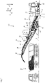
- a large road milling machine is shown as an example of the machine 10 according to the invention, the working device 12 of which is arranged with a milling drum 14 known per se, as is typical for large road milling machines, between the front chassis 16 and the rear chassis 18 .
- the running gears 16 and 18, which can be driven in each case preferably by a hydraulic motor (not shown) for the propulsion movement, can be steered and carry a machine frame 20, which in turn carries the working device 12.
- the machine 10 is thus a self-propelled vehicle.
- the direction of gravity is in the Figures 1 to 3 marked with an arrow g.
- the one to the character level of figure 1 orthogonal, parallel to the pitch axis Ni of the machine 10 running axis of rotation R rotatable milling drum 14 is shielded from the outside of the machine 10 by a milling drum box 22, which supports the milling drum 14 rotatably about the axis of rotation R.
- the milling drum box 22 is open to the subsoil U, on which the machine 10 with the running gears 16 and 18 stands and which the milling drum 14 removes, in order to enable the machine 10 to work the soil as intended.
- the machine frame 20 is connected to the chassis 16 and 18 via front lifting columns 17 and rear lifting columns 19 so that it can be adjusted in height along the yaw axis Gi, as a result of which the milling depth t of the milling drum 14 can be adjusted, for example.
- the machine 10 can be controlled from a control station 24 .
- the operator's stand 24 can be covered in a manner known per se.
- Soil material removed by the milling drum 14 during the intended soil tillage is conveyed by a transport device 26 from the working device 12 to a delivery location 28, where in the example shown it is transported to a transport truck accompanying the machine 10 during soil tillage at a distance in the direction of the roll axis Ro 30 is handed over.
- the transport device 26 comprises a receiving belt 32 located closer to the working device 12 and a discharge belt 34 which cooperates with the receiving belt 32 and is located further away from the working device 12.
- the receiving belt 32 can rotate, but is mounted on the machine frame 20 in an unchangeable manner with regard to its relative orientation to the machine frame 20 .
- the receiving belt 32 transfers the material it has conveyed to the discharge belt 34, which conveys the material that has been taken over to the delivery point 28.
- the discharge belt 34 is also rotatable, but can be pivoted relative to the machine frame 20 about a pivot axis S parallel to the yaw axis and can be tilted about a tilt axis orthogonal to the pivot axis S, so that the delivery location 28, which coincides with the discharge longitudinal end of the discharge belt 34, is approximately on the surface of a spherical cap is movable in order to adapt the delivery location 28 to the respective support vehicle.
- the transport device 26 is encased along its entire length by a housing 38 in order to prevent the external environment of the transport device 26 from being polluted by dust and material possibly falling from the transport device 26 .
- the part of the housing 38 located above the receiving belt 32 is largely realized by the machine frame 20 .
- the latter comprises a suction device 40 with a filter device 42.
- FIG 1 the suction device 40 is shown with a conveying fan 44' at the upper end of a filter housing 54.
- the filter device 42 is located on the suction side of the conveying fan 44', so that the air cleaned by the filter device 42 reaches the conveying fan 44' of the suction device 40 from figure 1 interspersed.
- the suction device 40 sucks in dust-laden air at a suction location 46, which can be located, for example, above the receiving belt 32, and conveys the dust-laden air in the specified sequence through a pre-filter 48 and through the filter device 42 to a blow-off location 50, which is either an outlet on the Conveyor fan 44', which blows off directly into the outside environment of the machine 10, or which can be an opening in the housing 38 above the discharge belt 34, through which the cleaned air is returned to the transport device 26, so that the cleaned air is combined escapes into the environment of the machine 10 with the removed soil material at the delivery point 28 .
- a suction location 46 which can be located, for example, above the receiving belt 32, and conveys the dust-laden air in the specified sequence through a pre-filter 48 and through the filter device 42 to a blow-off location 50, which is either an outlet on the Conveyor fan 44', which blows off directly into the outside environment of the machine 10, or which can be an opening in the housing 38 above the discharge belt 34,
- a filter body 52 is shown in the filter device 42 , the longitudinal axis of which is oriented essentially parallel to the transport direction or to the direction of travel of the discharge belt 34 .
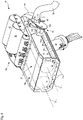
- the filter device 42 is more detailed than in FIG figure 1 shown.
- the filter device 42 includes the filter housing 54, in which in the example shown two, but very generally a plurality of filter bodies 52 are or is arranged.
- FIG 2 and 3 is the conveying fan 44 different from figure 1 shown in a lower portion of the filter housing 54 .
- the filter housing 54 or the filter device 42 is as in figure 1 functionally on the suction side of the conveying fan 44.
- figure 3 shows in particular the mirror-symmetrical design of the suction device 40 with regard to the first and the second hose lines 56 and 58, the pre-filter 48 and the conveying fan 44, which are each provided twice with respect to a mirror-symmetry plane spanned by the yaw axis Gi and the roll axis Ro, with the mirror symmetry applies to a stretched reference state, in which the discharge belt 34 and the transport direction of the discharge belt 34 are located in the plane of mirror symmetry.
- the conveying fan 44 conveys dust-laden air from the suction location 46 to the pre-filter 48 designed as a cyclone filter, where the dust-laden air is pre-cleaned in a manner known per se.
- the pre-cleaned air which is generally only polluted by fine dust with a grain size below a threshold size determined by the cyclone filter, is fed via a second hose line 58 to a bypass valve 60 , from where the pre-cleaned air enters the filter housing 54 .
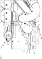
- the filter housing 54 has a larger compartment 54a in which the filter bodies 52 are accommodated and has a smaller compartment 54b in which no filter bodies 52 are accommodated.
- the filter bodies 52 are therefore located in an interior space 57 of the filter housing 54 or of the compartment 54a.
- the bypass valve 60 comprises a valve component 60a that is movable relative to the filter housing 54 and a valve component 60b that is fixed to the filter housing.
- the movable valve component 60a can, for example, be pivotable by 180° about a valve axis V relative to the valve component 60b fixed to the filter housing.
- an outlet orifice 62 of the second hose line 58 is preferred as a conveying channel upstream with respect to the bypass valve 60 via one of the plate-shaped, planar movable valve component 60a protruding connection formation 61, while the valve component 60b fixed to the filter housing has two inlet openings 64 and 66, of which the inlet opening 64 leads via a connection formation 63a into the compartment 54a of the filter housing 54, in which filter bodies 52 are accommodated, whereas the inlet opening 66 leads via a connection formation 63b into the compartment 54b without a filter body.
- a handle 68 is used to adjust the bypass valve 60 between its filter operating position, in which the bypass valve 60 connects the outlet orifice 62 with the inlet orifice 64, and the bypass operating position, in which the bypass valve 60 connects the outlet orifice 62 with of the inlet mouth 66 connects.
- a motor drive can also be provided for adjusting the bypass valve 60 between its two operating positions.
- An elastic sealing formation 65a or 65b surrounding the respective inlet orifice 64 or 66 can protrude from the valve component 60b fixed to the filter housing from the boundary surface 60b1 pointing towards the movable valve component 60a in order to bridge a separating gap between the valve components 60a and 60b in a gas-tight manner.
- the conveying fan 44 always sucks air away via the preferably smaller compartment 54b of the filter housing 54 that is free of filter bodies 52 . Depending on the position of the bypass valve 60, the conveying fan 44 sucks in air via the filter body 52 in the compartment 54a or directly via the inlet opening 66 without further filtering.
- the preferably plate-shaped movable valve component 60a is constructed asymmetrically in such a way that it closes that inlet opening on the side of the filter housing-fixed valve component 60b which is not connected to the outlet opening 62 of the movable valve component 60a. So an unwanted suction of false air is avoided by the conveyor fan 44, so that the entire Conveying effect of the conveying fan 44 relates to the air flow actually intended for conveying.
- two filter bodies 52 are shown by way of example in dashed lines in the interior space 57 of the compartment 54a. Both filter bodies 52 each extend along a longitudinal axis L, which is also the axis of rotation D of the respective filter body 52 . The filter bodies 52 are arranged with longitudinal axes L parallel. The filter bodies 52 are each connected about the axis of rotation D by an in figure 5 Rotary drive 70 shown rotatable.
- the filter bodies 52 are cantilevered at only one longitudinal end on rotary bearings 72, from which they cantilever along their longitudinal axis L or axis of rotation D.
- the rotary bearings 72 which represent embodiments of the filter body receptacles mentioned above, are arranged on the filter housing 54 and have a coupling formation with which a counter-coupling formation on a filter body 52 can be detachably coupled.
- filter bodies 52 can be quickly exchanged on the one hand and, on the other hand, arranged in the filter housing 54 so as to be rotatable about the axis of rotation D without their own means of relative movement.
- the rotary drive 70 preferably interacts directly with rotary bearings 72, so that the filter body 52 itself does not have to have any design for direct power transmission with the rotary drive 70.
- the rotary drive 70 and the rotary bearings 72 can have gear wheels or tooth structures that mesh with one another, the gear wheel of the rotary drive 70 being driven by a motor.
- This motor can be a hydraulic motor or, preferably, an electric motor.
- Another peripheral section of the filter body 52 can always be arranged in such a way that it points in the direction of gravity g, so that gravity consequently supports the loosening and falling of filter cakes, which accumulate on the dirty side of the filter material of the filter body 52 during filter operation .
- a peripheral portion of the filter body 52 then points in the direction of gravity g when a surface of the filter material or normal vector emanating from the envelope of the filter material has at least one component running in the direction of the effect of gravity.
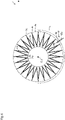
- FIG 6 A simplified cross-sectional view through the filter body 52 in a sectional plane orthogonal to the axis of rotation D is shown.
- the filter material 74 is a pleated filter material 74 which runs in a zigzag pattern around the axis of rotation D between an exemplary cylindrical radially outer envelope 74a and an exemplary cylindrical radially inner envelope 74b.
- Gravity acting direction g shown has the peripheral portion 75 of the filter material 74 in the gravitational acting direction g.
- the side of the filter material 74 pointing away from the axis of rotation D is the dirty side DS, on which filter cake forms during filter operation.
- the opposite side of the filter material 74 pointing to the axis of rotation D is the clean side CS, on which cleaned air flows after passing through the filter material 74 .
- the filter material 74 can be any porous material, such as a filter mat or a filter paper.
- the filter device 42 has a cleaning device 76 for removing filter cake from the filter material 74 of the filter bodies 52 .
- the cleaning device 76 comprises a pneumatic cleaning sub-device 76a and a mechanical cleaning sub-device 76b.
- the pneumatic partial cleaning device 76a comprises two compressed air tanks 78 and a valve arrangement 80 which is pneumatically connected to the compressed air tanks 78 and which is designed to discharge compressed air from the compressed air tanks 78 in bursts to the clean side CS of the filter material 74 of the filter bodies 52, so that the air pressure pressure surges that increase on the clean side CS compared to the dirty side DS are exerted on the filter material 74 . Due to these pressure surges, filter cake lying on the dirty side DS can be loosened or even ejected from the dirty side DS. The pressure surges can also bring about a deformation of the filter material 74 that supports the release of filter cake on the dirty side DS.
- a Control device 81 may be included, which controls the operation of the pneumatic cleaning sub-device 76a and the rotary drive 70.
- the pressure surges caused by the pneumatic cleaning sub-device 76a are matched to the rotational movement of the filter bodies 52 in terms of their duration and/or the distance between two consecutive pressure surges, so that it is ensured that the same circumferential section of the filter material 74 does not always point in the direction of gravity g when a pressure surge is applied. In this way it can be ensured that during a cleaning procedure the complete circumference of the filter body 52 is covered by the cleaning effect.
- a mechanical partial cleaning device 76b is provided, which supports the cleaning of the filter material 74 by subjecting it to mechanical stress.
- the mechanical partial cleaning device 76b comprises a wiper strip 82 which extends along the longitudinal axis or axis of rotation L or D of the filter body 52 .
- the wiper strip preferably extends through the radially outer envelope end 74a, which is cylindrical in the example shown, towards the axis of rotation D of the filter body 52, as is shown in figure 6 is shown.
- the radially outer folds 74c of the pleated filter material then scrape off the wiper strip 82, which temporarily increases the distance between two radially outer folds 74c that follow one another in the circumferential direction, so that filter cake caught between these folds can fall out more easily, and on the other hand, after the end of the contact engagement of the wiper strip 82 with a radially outer fold 74c, a force acting on the radially outer fold 74c and deforming it in the circumferential direction ends abruptly, so that the radially outer fold 74c, which was initially deformed in the circumferential direction, due to its material elasticity returns to its original shape, which can have a further filter cake-dissolving effect. Finally the Squeegee bar 82 mechanically along at least part of the filter material 74 and thus scrapes filter cake from the filter material 74 mechanically.
- the wiper strip 82 has a plurality of projections 84 on its side pointing towards the axis of rotation D, each of which protrudes from a support area 82a of the wiper strip 82 towards the axis of rotation D and thus towards the filter body 52.
- Each projection 84 has a web area 84a located closer to the carrier area 82a and preferably integrally connected thereto, and a stripping area 84b adjoining the web area 84a toward the axis of rotation D and preferably integrally connected thereto.
- the web area 84a of a projection 84 is shorter in the longitudinal direction of the wiper strip 82 than the wiper area 84b, which preferably projects beyond the web area 84a in the longitudinal direction of the wiper strip 82 on both sides.
- the wiping area 84b of each projection 84 thus provides the greatest possible wiping length and the web area 84a defines the deformation resistance of the projection 84 and thus the maximum load exerted by the wiping strip 82 on the filter material 74 .
- the wiper strip 82 can thus advantageously be made of stainless sheet steel. All projections 84 are preferably of identical design.
- the filter housing 54 has a housing base 86 pointing towards the discharge belt 34 when the filter device 42 is in the ready-to-use state, which in figure 5 is shown in dashed lines in a position lifted from the rest of the filter housing 55, ie the filter housing 54 without the housing base 86. In the usual, non-raised position, the housing base 86 is covered by the side wall of the filter housing 54 .
- the case back 86 is made of an elastomeric material, such as caoutchouc, gum, silicone rubber, etc.
- the case back 86 may be reinforced with inserts, such as fabric or scrim, to increase the case back 86's tear strength.
- the rest of the filter housing 55 is off in the example shown sheet metal built. However, this does not have to be the case.
- the filter housing 54 can have more than one wall made of an elastomeric material.
- the lower end 86a of the housing base 86 is coupled to an actuator 88 fixed to the filter housing 54 or to the housing 38 .
- the actuator 88 can be a pneumatic or a hydraulic actuator and can include a piston rod that can be extended from and retracted into a cylinder as the actuating element 90, or can be an electric or electromagnetic actuator whose actuating element 90 can be displaced electrically or electromagnetically.
- actuator 90 of actuator 88 is shown in phantom.
- the lower longitudinal end 86a of the housing base 86 is lifted off the rest of the filter housing 55, so that an outlet opening 92 is formed between the housing base 86, more precisely between its lower longitudinal end 86a and the rest of the filter housing 55, through which material to the transport device 26, more precisely towards the discharge belt 34, can be let out of the interior 57 of the filter housing 54, which has accumulated in the filter housing 54, in particular in the compartment 54a accommodating the filter bodies 52, in the course of operation.
- this is material which the extracted air has carried along and which has been filtered out of the air by the filter body 52 and/or which has been deposited on the inner walls of the filter housing 54 .
- the material can range from excavated soil material in the form of dust to shards of baked material.
- the removed soil material usually has a high level of moisture, since water is usually injected into the milling drum box 22 in order to prevent excessive formation of dust and to cool the milling cutters.
- the mineral soil material that has been removed tends to cake in a damp environment, a property that is particularly important for binding dust by injecting uses water. Mineral, rock-hard deposits can form on the inner surfaces of the filter housing.
- the deformable design of the housing base 86 through the use of elastomer material has another advantageous effect: through the targeted deformability of the housing base 86, soil material sticking to it can be detached from the housing base 86.
- An elastomeric wall of the filter housing 54 can be deformed in a simple manner by the cleaning device 76, more precisely by the pneumatic cleaning sub-device 76a. If this increases the pressure in the interior 57 of the filter housing 54, the deformable walls of the filter housing 54 bulge outwards, as a result of which the mineral layers of excavated soil material that are stuck and bonded to them flake off and can lie around loosely as shards in the interior 57 of the filter housing 54. The shards that have broken off can then be delivered to the transport device 26 through the outlet opening 92 and transported by it to the drop-off point 28 .
- the valve arrangement 80 can increase the pressure in the interior 57 of the filter housing 54, in particular in the compartment 54a, in a simple manner via pneumatic lines connected to it.
- the valve arrangement 80 can be actuated from the driver's station 24 .
- the control device 81 can also trigger a cleaning process of the filter housing 54 at predetermined time intervals by appropriately actuating the valve arrangement 80 .
- the conveying fan 44 can create a negative pressure in the filter housing 54 generate because the filter housing 54 is on the suction side of the conveyor fan 44.
- the filter housing 54 and thus its walls can be exposed to an alternating overpressure-underpressure load, which causes a flexing movement of the walls of the filter housing 54 further facilitates the detachment of hardened soil material sticking to it.
- the compressed air tanks 78 can also be connected via the valve arrangement 80 to an on-board compressor, which ensures a constant or quasi-constant level of compressed air in the compressed air tanks 78 .
Landscapes
- Engineering & Computer Science (AREA)
- Chemical & Material Sciences (AREA)
- Chemical Kinetics & Catalysis (AREA)
- Architecture (AREA)
- Civil Engineering (AREA)
- Structural Engineering (AREA)
- Mining & Mineral Resources (AREA)
- Mechanical Engineering (AREA)
- Physics & Mathematics (AREA)
- Geometry (AREA)
- Filtering Of Dispersed Particles In Gases (AREA)
Description
- Die vorliegende Erfindung betrifft eine selbstfahrende Bodenbearbeitungsmaschine, wie etwa eine Straßenfräse, einen Recycler oder einen Surface-Miner, wobei die Bodenbearbeitungsmaschine umfasst:
- einen von einer Mehrzahl von Ketten- oder/und Radlaufwerken höhenverstellbar getragenen Maschinenrahmen,
- eine Arbeitsvorrichtung zur Material abtragenden Bearbeitung eines Bereichs eines Bodens, und
- eine Absaugeinrichtung, welche dazu ausgebildet ist, staubbelastete Luft an wenigstens einem Absaugort aus wenigstens einem Maschinenbereich abzusaugen und abgesaugte Luft an einem vom Absaugort verschiedenen Abblasort auszublasen,
- ein Filtergehäuse, und
- einen im Filtergehäuse aufgenommenen Filterkörper, wobei der Filterkörper dazu ausgebildet ist, Staubpartikel aus der die Filtervorrichtung durchströmenden Luft zu entfernen.
- Eine solche Bodenbearbeitungsmaschine in Ausführungsform einer Boden-, insbesondere Straßenfräsmaschine ist beispielsweise aus der
DE 10 2004 007 716 B3 bekannt. - Das von der Arbeitsvorrichtung abgetragene Bodenmaterial wird - im Stand der Technik ebenso wie bevorzugt auch in der vorliegenden Erfindung - ausgehend von einem Arbeitsvorrichtungsgehäuse, in welchem die Arbeitsvorrichtung zur Ausführung einer Abtragsbewegung beweglich aufgenommen ist, mittels eines Transportbandes zu einem Abgabeort gefördert. Das Arbeitsvorrichtungsgehäuse schirmt als Arbeitsschutzvorrichtung die Umgebung der Arbeitsvorrichtung vor der Arbeitsvorrichtung und dem durch sie abgetragenen Bodenmaterial ab. Am Abgabeort wird das geförderte abgetragene Bodenmaterial in der Regel abgeworfen, häufig auf ein die mobile, selbstfahrende Bodenbearbeitungsmaschine begleitendes Fahrzeug, welches das aufgenommene abgetragene Bodenmaterial entsorgt oder weiterverarbeitet.
- Am Eingriffsort der abtragenden Arbeitsvorrichtung mit dem zu bearbeitenden Boden werden Bodenmaterialstücke unterschiedlich großer Körnung aus dem Boden herausgetrennt. Diese Bodenmaterialstücke bewegen sich mit hoher kinetischer Energie in dem Arbeitsvorrichtungsgehäuse und prallen auf die Wandung des Arbeitsvorrichtungsgehäuses, kollidieren untereinander oder/und mit Wirkflächen von Auswerfern an der Arbeitsvorrichtung sowie mit der Arbeitsvorrichtung selbst. Bei diesen Kollisionen entstehen, wie schon beim Abtrag des Bodenmaterials durch die Arbeitsvorrichtung, Stäube unterschiedlicher Körnung bis hin zum Feinstaub. Es sind diese Stäube, die die durch die Absaugeinrichtung abgesaugte Luft belasten. Die Stäube können in dem Arbeitsvorrichtungsgehäuse oder/und beim Transport des abgetragen Bodenmaterials in den das abgetragene Bodenmaterial umgebenden Luftraum übergehen. Dies gilt für den Stand der Technik ebenso wie für die vorliegende Erfindung.
- Bereits die
DE 102 23819 A1 lehrt, die durch die Bodenbearbeitung entstehende staubbelastete Luft an einem näher bei der Arbeitsvorrichtung gelegenen Absaugort abzusaugen und in einem weiter von der Arbeitsvorrichtung entfernt gelegenen Abblasort auf das Transportband abzublasen. Durch eine Berieselungseinrichtung, welche die Umgebung des Abblasorts mit Wasser berieselt oder/und durch eine elektrostatische Abscheidevorrichtung kann Staub in der am Abblasort abgeblasenen Luft aus der Luft entfernt werden. - Die
DE 10 2004 007 716 B3 lehrt, zur Erhöhung der Standfestigkeit eines die staubbelastete Luft fördernden Fördergebläses eine Filtervorrichtung im Strömungsweg der staubbelasteten Luft vom Absaugort zum Abblasort stromaufwärts des Fördergebläses anzuordnen und so die Luft zu reinigen, bevor sie das Fördergebläse erreicht. Die bekannte Filtervorrichtung umfasst ein Filtergehäuse, in welchen eine Mehrzahl von sogenannten "Filterkartuschen" als Filterkörper aufgenommen ist, um eine möglichst große Filterfläche zu erzielen. - Da die Filterkörper auf ihrer Schmutzseite mit zunehmender Dauer des Filterbetriebs einen Filterkuchen bilden, welcher bei Überschreiten einer kritischen Größe die Filterwirkung des jeweiligen Filterkörpers beeinträchtigt, lehrt die
DE 10 2004 007 716 B3 weiterhin, die Filterkörper durch Vibration oder durch einen auf der Reinseite des Filterkörpers realisierten Druckluftimpuls vom Filterkuchen zu befreien. Der vom Filterkörper abgereinigte Filterkuchen kann durch eine Formation, etwa eine Klappe oder ein verformbarer Bereich, im Boden des Filtergehäuses auf das Transportband abgegeben werden. Das Filtergehäuse ist über dem Transportband angeordnet. Das Transportband ist durch eine Abdeckung von der Außenumgebung abgeschirmt, sodass auf dem Transportband aufliegendes Bodenmaterial nicht oder nur in sehr geringem Umfang vom Transportband während der Förderung bis zum Abgabeort in die Umgebung gelangen kann. - Aufgrund der starken Staubbelastung der vom Absaugort weg geförderten Luft ist die von dem wenigstens einen Filterkörper geforderte Filterleistung erheblich. Dies bedeutet, dass eine große Filterfläche benötigt wird oder/und dass der wenigstens eine Filterkörper verschleißbedingt in verhältnismäßig kurzen Zeitabständen getauscht werden muss, um die gewünschte Filterleistung zu erhalten.
- Es ist daher Aufgabe der vorliegenden Erfindung, die eingangs genannte mobile, selbstfahrende Bodenbearbeitungsmaschine derart weiterzubilden, dass ohne Vergrößerung der Filterfläche die Standzeit des wenigstens einen Filterkörpers verlängert werden kann, bis dessen verschleißbedingter Austausch notwendig ist.
- Diese Aufgabe wird erfindungsgemäß durch eine mobile, selbstfahrende Bodenbearbeitungsmaschine der eingangs genannten Art gelöst, bei welcher die Filtervorrichtung zum Umschalten zwischen einer Filterung der abgesaugten Luft und lediglich einer Förderung der ungefilterten oder durch einen Vorfilter, wie etwa Zyklonfilter, vorgefilterten abgesaugten Luft ohne weitere Filterwirkung ein zwischen wenigstens zwei unterschiedlichen Betriebsstellungen verstellbares Bypass-Ventil aufweist. In einer Filter-Betriebsstellung verbindet dann das Bypass-Ventil den wenigstens einen Absaugort mit dem Abblasort unter Durchströmung des Filterkörpers. In einer Bypass-Betriebsstellung verbindet das Bypass-Ventil den wenigstens einen Absaugort mit dem Abblasort unter Umgehung des Filterkörpers. Bevorzugt weist das Bypass-Ventil nur die Filter- und die Bypass-Betriebsstellung auf.
- Die Standzeit des Filterkörpers kann also dadurch erhöht werden, dass ein Filterbetrieb der Filtervorrichtung nur dann erfolgt, wenn dieser tatsächlich benötigt wird. So ist in ohnehin bereits feinstaubbelasteten Innenstädten ein Betrieb der Filtervorrichtung geboten, um eine Erhöhung der Feinstaubbelastung zu vermeiden, wohingegen während einer Bodenbearbeitung außerhalb von geschlossenen Ortschaften ein Filtern der abgesaugten staubbelasteten Luft nicht unbedingt notwendig ist. Befindet sich der Abblasort ausreichend weit von einem Fahrstand der Bodenbearbeitungsmaschine entfernt, auf welchem eine die Bodenbearbeitungsmaschine steuernde Bedienperson während einer Bodenbearbeitung tätig ist, ist die Staubbelastung der Bedienperson vernachlässigbar. Dann, wenn gemäß einer bevorzugten Weiterbildung die zunächst abgesaugte staubbelastete Luft in einen Kanal abgeblasen wird, welcher eine das abgetragene Bodenmaterial fördernde Transportvorrichtung umgibt, tritt die abgeblasene Luft erst am Abgabe- bzw. Abwurfort des Bodenmaterials von der Transportvorrichtung ins Freie. Dieser Abgabeort ist während eines bestimmungsgemäßen Bodenbearbeitungsbetriebs in der Regel der am weitesten vom Fahrstand entfernte Ort der Bodenbearbeitungsmaschine.
- Das Bypass-Ventil kann konstruktiv einfach aufgebaut sein. Es kann ein bewegliches Ventilbauteil aufweisen, welches eine Austrittsmündung eines stromaufwärtigen Förderkanals der staubbelasteten Luft aufweist. Durch Bewegung des Ventilbauteils kann die Austrittsmündung des stromaufwärtigen Förderkanals mit einer gewünschten von zwei Eintrittsmündungen auf einer stromabwärtigen Seite des Bypass-Ventils, insbesondere eines Trennspalts zwischen Austrittsmündung und Eintrittsmündungen, strömungsführend verbunden werden.
- Das Bypass-Ventil kann ein relativ zum Filtergehäuse bewegliches Ventilbauteil und ein filtergehäusefestes Ventilbauteil umfassen. Das bewegliche Ventilbauteil kann um eine Ventilachse relativ zum filtergehäusefesten Ventilbauteil um einen vorbestimmten Winkel, zur effektiven Trennung der beiden Betriebsstellungen und somit zur Vermeidung von unerwünschten Fehlstellungen oder Fehlbetätigungen bevorzugt um 180°, schwenkbar sein. Alternativ oder zusätzlich kann das bewegliche Ventilbauteil relativ zum filtergehäusefesten Ventilbauteil translatorisch verschiebbar sein. Mit dem beweglichen Ventilbauteil kann eine Austrittsmündung eines bezüglich des Bypass-Ventils stromaufwärtigen Förderkanals verbunden sein.
- Das filtergehäusefeste Ventilbauteil kann die oben genannten zwei Eintrittsmündungen aufweisen, von denen eine erste Eintrittsmündung in ein erstes Kompartiment des Filtergehäuses führt, in welchem wenigstens ein Filterkörper aufgenommen ist, und von denen eine zweite Eintrittsmündung in ein zweites Kompartiment des Filtergehäuses führt, welches keine Filterwirkung entfaltet, etwa, weil im zweiten Kompartiment keine Filterkörper zur Durchströmung mit staubbelasteter Luft angeordnet sind.
- Bevorzugt ist das bewegliche Ventilbauteil dabei derart aufgebaut, insbesondere asymmetrisch aufgebaut, dass es diejenige Eintrittsmündung auf Seiten des filtergehäusefesten Ventilbauteils verschließt, welche nicht mit der Austrittsmündung des beweglichen Ventilbauteils verbunden ist. So kann ein unerwünschtes Ansaugen von Falschluft durch das Fördergebläse vermieden werden. Daher kann sich in vorteilhafter Weise die gesamte Förderwirkung des Fördergebläses auf den tatsächlich zur Förderung von staubbelasteter Luft bestimmten Luftstrom beziehen.
- Das bewegliche Ventilbauteil oder/und das filtergehäusefeste Ventilbauteil können zur Sicherstellung eines Verschließens der in der jeweiligen Betriebsstellung des Bypass-Ventils nicht aktivierten Eintrittsmündung wenigstens an den aufeinander zuweisenden Seiten der Ventilbauteile mit einer ebenen Grenzfläche ausgebildet sein. Die Eintrittsmündungen oder die Austrittsmündung können mit, vorzugsweise elastischen, besonders bevorzugt elastomeren, zum jeweils anderen Ventilbauteil vorstehenden Dichtungsformationen versehen sein, um einen Trennspalt zwischen dem beweglichen Ventilbauteil und dem filtergehäusefesten Ventilbauteil möglichst gasdicht zu überbrücken. Bevorzugt kann bzw. können das bewegliche Ventilbauteil oder/und das filtergehäusefeste Ventilbauteil ein plattenförmiges, ebenes Bauteil umfassen, von welchem ausgehend wenigstens eine Anschlussformation zum Anschluss eines Luft leitenden Förderkanals auf der stromaufwärtigen Seite des beweglichen Ventilbauteils abstehen kann oder/und wenigstens eine Anschlussformation auf der stromabwärtigen Seite des filtergehäusefesten Ventilbauteils abstehen kann. Bevorzugt steht auf der der stromabwärtigen Seite des filtergehäusefesten Ventilbauteils von jeder Eintrittsmündung je eine Anschlussformation ab.
- Grundsätzlich kann das Bypass-Ventil von Hand zwischen seinen unterschiedlichen Luftströmungswegen zugeordneten Betriebsstellungen bewegbar sein. Bevorzugt umfasst das Bypass-Ventil einen Ventilantrieb, welcher auf Betätigung eines Steuerschalters am Fahrstand der Bodenbearbeitungsmaschine das Bypass-Ventil zwischen wenigstens zwei seiner Betriebsstellungen verstellt.
- Konstruktiv kann gemäß einer bevorzugten Ausführungsform der erfindungsgemäßen Bodenbearbeitungsmaschine das Bypass-Ventil in der Filter-Betriebsstellung den wenigstens einen Absaugort derart mit dem Filtergehäuse verbinden, dass ein den Filterkörper aufnehmender Innenraum des Filtergehäuses Teil der den wenigstens einen Absaugort mit dem Abblasort verbindenden Strömungsleitung für staubbelastete Luft ist. Weiter kann das Bypass-Ventil in der Bypass-Betriebsstellung den wenigstens einen Absaugort mit dem Abblasort unter Umgehung des den Filterkörper aufnehmenden Innenraums des Filtergehäuses und damit des Filterkörpers verbinden.
- In der vorliegenden Anmeldung ist zur Beschreibung der vorgestellten Erfindung von einem Filterkörper die Rede. Dies dient lediglich der Veranschaulichung und ist keine Mengenangabe. Wenngleich ein einziger Filterkörper ausreichen kann, weist die Filtervorrichtung der vorliegenden Erfindung bevorzugt eine Mehrzahl von Filterkörpern auf. Jeder Filterkörper kann um eine Drehachse drehbar im Filtergehäuse gelagert sein. Dann sind bevorzugt die Drehachsen der Filterkörper zur vorteilhaft effizienten Ausnutzung des vorhandenen Bauraums zueinander parallel.
- Auch die Filterkörper der vorliegenden Erfindung sind bevorzugt grob-zylindrische Filterkörper mit einer zylindrischen Einhüllenden oder grob-konische Filterkörper mit einer konischen Einhüllenden. Zu den grob-konischen Filterkörpern gehören auch kegelstumpfförmige Filterkörper. An ihren Längsenden können die Filterkörper von einer idealen Zylinder- oder Konusform abweichen, etwa weil die Filterkörper eine Kopplungsformation zur Kopplung mit einer Kopplungsgegenformation am Filtergehäuse erfordern oder/und weil von der Einhüllenden eingehülltes poröses Filtermaterial des Filterkörpers an beiden Längsendbereichen des Filterkörpers körperlich, etwa durch entsprechende Endstücke lagedefiniert sein soll.
- Die vorliegend diskutierte mobile Bodenbearbeitungsmaschine ist eine selbstfahrende Bodenbearbeitungsmaschine, welche einen von einer Mehrzahl von Ketten-oder/und Radlaufwerken höhenverstellbar getragenen Maschinenrahmen aufweist. Der Maschinenrahmen trägt wiederum - bevorzugt bestimmungsgemäß lösbar - die Arbeitsvorrichtung, welche gemäß einer bevorzugten Ausführungsform eine Fräswalze mit einem zylindrischen Grundkörper ist, auf welchem Fräsmeißel, und vorzugsweise auch Auswerfer, angeordnet sind. Das eingangs genannte Arbeitsvorrichtungsgehäuse, welches die Bodenbearbeitungsmaschine zur Abschirmung der Arbeitsvorrichtung in vorteilhafter Weiterbildung aufweist, ist dann ein sogenannter "Fräswalzenkasten". Zum erleichterten Wechsel der während der abtragenden Bodenbearbeitung stark verschleißbeanspruchten Fräsmeißel sind an der Außenseite des zylindrischen Grundkörpers Meißelwechselhalter angeordnet, in welchen Fräsmeißel bestimmungsgemäß lösbar aufgenommen sind. Zum erleichterten Abtransport des durch die Fräsmeißel vom Boden abgetragenen Bodenmaterials sind die Meißelwechselhalter bevorzugt grob wendelförmig auf dem Grundkörper angeordnet, um bei Rotation der Fräswalze eine auf das abgetragene Bodenmaterial ausgeübte axiale Förderwirkung längs der Rotationsachse der Fräswalze zu erzielen. Üblicherweise verlaufen von jedem axialen Längsende der Fräswalze je wenigstens eine Meißelwechselhalter-Wendel zur axialen Fräswalzenmitte hin, um von jedem Längsende eine axiale Förderwirkung zur axialen Fräswalzenmitte zu erzeugen.
- Zur Förderung der staubbelasteten Luft kann die Bodenbearbeitungsmaschine in vorteilhafter Weiterbildung der Erfindung ein Fördergebläse aufweisen, wobei die Filtervorrichtung, insbesondere der Filterkörper, bevorzugt auf der Saugseite des Fördergebläses liegt, sodass die vom Fördergebläse geförderte Luft das Fördergebläse in gereinigtem Zustand erreicht. Je weniger Staubpartikel in der geförderten Luft enthalten sind, desto weniger abrasiv wirkt die geförderte Luft auf das Fördergebläse. Das Fördergebläse kann einen gegenüber staubbelasteter Luft robusten Axiallüfter umfassen. Alternativ kann das Fördergebläse einen weniger Bauraum als ein Axiallüfter gleicher Förderleistung einnehmenden Radiallüfter umfassen.
- Wenn in der vorliegenden Anmeldung von einer bestimmungsgemäß lösbaren Anordnung die Rede ist, so ist damit eine zerstörungsfrei lösbare Anordnung bezeichnet, wie sie beispielsweise durch Schraubverbindungen, Bajonettverbindungen und dergleichen bewirkt werden kann, im Gegensatz zu nicht-lösbaren Anordnungen, wie beispielsweise Schweiß- oder Nietverbindungen, welche lediglich zerstörend aufgehoben werden können.
- Ein Abschnitt weist gemäß der vorliegenden Anmeldung in eine Richtung, wenn eine von dem Abschnitt ausgehende Flächennormale eine Komponente aufweist, welche in die angegebene Richtung weist.
- Ein verschlissener Filterkörper kann dadurch besonders einfach und schnell gegen einen unverschlissenen ausgetauscht werden, wenn er an einem Längsende, bevorzugt nur an einem Längsende, mit einer Filterkörperaufnahme lösbar koppelbar ist. Dabei reicht es zur Erzielung einer bevorzugten Drehbarkeit des Filterkörpers aus, wenn die am Filtergehäuse angeordnete Filterkörperaufnahme um die Drehachse drehbar im oder am Filtergehäuse aufgenommen ist. Der Filterkörper selbst braucht dann keinerlei Drehbarkeit bereitzustellen oder/und keinerlei Formation aufzuweisen, um von einem Drehantrieb ein Antriebsdrehmoment auf den Filterkörper zu übertragen. Eine solche mit dem Drehantrieb wechselwirkende Formation kann alleine an der Filterkörperaufnahme ausgebildet sein.
- Grundsätzlich weist der Filterkörper eine bezüglich einer Betriebsströmungsrichtung der staubbelasteten Luft vom Absaugort zum Abblasort stromaufwärts eines die Filterwirkung des Filterkörpers bereitstellenden porösen Filtermaterials gelegene Schmutzseite und eine stromabwärts des Filtermaterials gelegene Reinseite auf.
- Sofern in der vorliegenden Anmeldung nichts Abweichendes gesagt ist, beziehen sich die Angaben "stromaufwärts" und "stromabwärts" auf die Betriebsströmungsrichtung der staubbelasteten Luft vom Absaugort zum Abblasort.
- Der Absaugort liegt näher bei der Arbeitsvorrichtung als der Abblasort, weil in einem zur Arbeitsvorrichtung führenden Luftkanal die Staubbelastung der Luft mit zunehmender Annäherung an die Arbeitsvorrichtung ansteigt.
- Um die Belastung des Filterkörpers der Filtervorrichtung im Filterbetrieb zu verringern, kann die Filtervorrichtung einen vom Filterkörper verschiedenen Vorfilter aufweisen, welcher bevorzugt außerhalb des Filtergehäuses angeordnet ist, sodass nur vorgereinigte staubbelastete Luft zum Filterkörper geleitet wird. Als derartige Vorfilter haben sich sogenannte Zyklonfilter bewährt, welche Staubpartikel oberhalb einer bestimmten Korngröße aus der staubbelasteten Luft entfernen. Somit erreichen den wenigstens einen Filterkörper im Filtergehäuse bevorzugt nur Staubpartikel unterhalb einer bestimmten Korngröße oder eines bestimmten Korngrößenbereichs. Das Filtermaterial des Filterkörpers kann hinsichtlich seiner Porosität und seiner Durchlässigkeit auf den Korngrößenbereich der Staubpartikel in der vorgereinigten Luft besonders gut abgestimmt werden, sodass die Reinigungswirkung des Filterkörpers weiter erhöht werden kann.
- Wie eingangs bereits geschildert, weist die Bodenbearbeitungsmaschine bevorzugt eine Transportvorrichtung auf, durch welches von der Arbeitsvorrichtung abgetragenes Bodenmaterial in Richtung von der Arbeitsvorrichtung weg zu einem Abgabeort förderbar ist. Um die pro Zeiteinheit anfallenden Mengen an abgetragenem Bodenmaterial sicher abtransportieren zu können umfasst die Transportvorrichtung bevorzugt als Transportmittel wenigstens ein Förderband, vorzugsweise wenigstens zwei in Förderrichtung aufeinander folgende Förderbänder, welche zur Reduzierung der Schmutzbelastung der Umgebung der Bodenbearbeitungsmaschine über wenigstens 90 % ihrer Förderstrecke eingehaust ist bzw. sind. Es sind jedoch auch andere Transportvorrichtungen nicht ausgeschlossen, wie beispielsweise Schneckenförderer und dergleichen.
- Gemäß einer vorteilhaften Weiterbildung ist das Filtergehäuse über der Transportvorrichtung angeordnet. Dann kann das, in der Regel mineralisch gebundene, Staubpartikelmaterial schwerkraftgetrieben das Filtergehäuse verlassen und die Transportvorrichtung erreichen, wo es mit dem abgetragenem Bodenmaterial zum Abgabeort transportiert wird.
- Die vorliegende Erfindung wird nachfolgend anhand der beiliegenden Zeichnungen erläutert. Es stellt dar:
- Fig. 1
- eine grobschematische Seitenansicht einer erfindungsgemäßen Bodenbearbeitungsmaschine während einer Bodenmaterial abtragenden Bearbeitung,
- Fig. 2
- eine ausschnittsweise Vergrößerung des Abwurfbandes der Transportvorrichtung mit daran angeordneter Filtervorrichtung der Bodenbearbeitungsmaschine von
Figur 1 in perspektivischer Ansicht, - Fig. 3
- eine perspektivische grobschematische Ansicht der Filtervorrichtung von
Figur 2 , einschließlich Vorfilter der Bodenbearbeitungsmaschine vonFigur 1 , - Fig. 4
- eine perspektivische grobschematische Ansicht der Filtervorrichtung von
Figur 3 , ohne Vorfilter, von schräg vorne und oben, - Fig. 5
- eine vergrößerte grobschematische Seitenansicht des Bypass-Ventils der Filtervorrichtung der Bodenbearbeitungsmaschine von
Figur 1 , und - Fig. 6
- eine grobschematische beispielhafte Querschnittansicht durch das Filtermaterial eines Filterkörpers der Filtervorrichtung der
Figuren 1 bis 5 . - In
Figur 1 ist eine erfindungsgemäße Bodenbearbeitungsmaschine (nachfolgend kurz als "Maschine" bezeichnet) allgemein mit 10 bezeichnet. Beispielhaft ist als erfindungsgemäße Maschine 10 eine Straßengroßfräse dargestellt, deren Arbeitsvorrichtung 12 mit einer an sich bekannten Fräswalze 14, wie für Straßengroßfräsen typisch, zwischen den vorderen Fahrwerken 16 und den hinteren Fahrwerken 18 angeordnet ist. Die jeweils vorzugsweise durch einen nicht dargestellten Hydromotor zur Vortriebsbewegung antreibbaren Fahrwerke 16 und 18 sind lenkbar und tragen einen Maschinenrahmen 20, welche wiederum die Arbeitsvorrichtung 12 trägt. Die Maschine 10 ist somit ein selbstfahrendes Fahrzeug. - Die Schwerkraftwirkungsrichtung ist in den
Figuren 1 bis 3 mit einem Pfeil g gekennzeichnet. - Die um eine zur Zeichenebene von
Figur 1 orthogonale, parallel zur Nickachse Ni der Maschine 10 verlaufende Rotationsachse R rotierbare Fräswalze 14 ist durch einen Fräswalzenkasten 22, welcher die Fräswalze 14 um die Rotationsachse R rotierbar lagert, zur Außenumgebung der Maschine 10 abgeschirmt. Der Fräswalzenkasten 22 ist zum Untergrund U, auf welchem die Maschine 10 mit den Fahrwerken 16 und 18 aufsteht, und welchen die Fräswalze 14 abträgt, hin offen, um die bestimmungsgemäße Bodenbearbeitung der Maschine 10 zu ermöglichen. - Der Maschinenrahmen 20 ist längs der Gierachse Gi höhenverstellbar über vordere Hubsäulen 17 und hintere Hubsäulen 19 mit den Fahrwerken 16 und 18 verbunden, wodurch beispielsweise die Frästiefe t der Fräswalze 14 einstellbar ist.
- Die Maschine 10 ist von einem Fahrstand 24 aus steuerbar. Der Fahrstand 24 kann in an sich bekannter Weise überdacht sein.
- Von der Fräswalze 14 während der bestimmungsgemäßen Bodenbearbeitung abgetragenes Bodenmaterial wird von einer Transportvorrichtung 26 von der Arbeitsvorrichtung 12 zu einem Abgabeort 28 gefördert, wo es im dargestellten Beispiel einem die Maschine 10 während der Bodenbearbeitung mit Abstand in Richtung der Rollachse Ro vorausfahrend-begleitenden Transport-Lkw 30 übergeben wird.
- Die Transportvorrichtung 26 umfasst ein näher bei der Arbeitsvorrichtung 12 gelegenes Aufnahmeband 32 und ein mit dem Aufnahmeband 32 kooperierendes, weiter von der Arbeitsvorrichtung 12 entfernt gelegenes Abwurfband 34. Das Aufnahmeband 32 ist umlauffähig, aber hinsichtlich seiner relativen Orientierung zum Maschinenrahmen 20 unveränderlich am Maschinenrahmen 20 gelagert. An einer Übergabestelle 36 übergibt das Aufnahmeband 32 das von ihm geförderte Material an das Abwurfband 34, welches das übernommene Material bis zum Abgabeort 28 fördert. Das Abwurfband 34 ist ebenfalls umlauffähig, jedoch relativ zum Maschinenrahmen 20 um eine gierachsenparallele Schwenkachse S schwenkbar und um eine zur Schwenkachse S orthogonale Neigeachse neigbar, sodass der Abgabeort 28, welcher mit dem abwerfenden Längsende des Abwurfbands 34 zusammenfällt, in etwa auf der Oberfläche einer Kugelkalotte beweglich ist, um den Abgabeort 28 an das jeweilige Begleitfahrzeug anzupassen.
- Die Transportvorrichtung 26 ist längs ihrer gesamten Länge durch eine Einhausung 38 eingehaust, um eine Belastung der Außenumgebung der Transportvorrichtung 26 durch Staub und durch von der Transportvorrichtung 26 möglicherweise herabfallendes Material zu vermeiden. Der über dem Aufnahmeband 32 gelegene Teil der Einhausung 38 ist größtenteils durch den Maschinenrahmen 20 realisiert.
- Zur weiteren Verringerung der Schmutzemission, insbesondere Staubemission, der Maschine 10 durch die Arbeitsvorrichtung 12 umfasst diese eine Absaugeinrichtung 40 mit einer Filtervorrichtung 42.
- Um anzudeuten, dass die Absaugeinrichtung 40 in unterschiedlicher Weise ausgestaltet sein kann, ist in
Figur 1 die Absaugeinrichtung 40 mit einem Fördergebläse 44' am oberen Ende eines Filtergehäuses 54 dargestellt. Die Filtervorrichtung 42 ist auf der Saugseite des Fördergebläses 44' gelegen, sodass durch die Filtervorrichtung 42 gereinigte Luft das Fördergebläse 44' der Absaugeinrichtung 40 vonFigur 1 durchsetzt. - Die Absaugeinrichtung 40 saugt staubbelastete Luft an einem Absaugort 46 an, der beispielsweise über dem Aufnahmeband 32 gelegen sein kann, und fördert die staubbelastete Luft in der angegebenen Reihenfolge durch einen Vorfilter 48 und durch die Filtervorrichtung 42 zu einem Abblasort 50, welcher entweder ein Auslass am Fördergebläse 44' sein kann, der direkt in die Außenumgebung der Maschine 10 abbläst, oder welcher über dem Abwurfband 34 eine Mündung in der Einhausung 38 sein kann, durch welche hindurch die gereinigte Luft wieder zurück zur Transportvorrichtung 26 gegeben wird, sodass die gereinigte Luft zusammen mit dem abgetragenen Bodenmaterial am Abgabeort 28 in die Umgebung der Maschine 10 austritt.
- In der Filtervorrichtung 42 ist ein Filterkörper 52 gezeigt, dessen Längsachse im Wesentlichen parallel zur Transportrichtung bzw. zur Verlaufsrichtung des Abwurfbandes 34 orientiert ist.
- In den
Figuren 2 und3 ist die Filtervorrichtung 42 stärker detailliert als inFigur 1 dargestellt. Die Filtervorrichtung 42 umfasst das Filtergehäuse 54, in welchem im dargestellten Beispiel zwei, ganz allgemein jedoch eine Mehrzahl von Filterkörpern 52 angeordnet sind bzw. ist. - In den
Figur 2 und3 ist das Fördergebläse 44 abweichend vonFigur 1 in einem unteren Abschnitt des Filtergehäuses 54 dargestellt. Jedoch liegt das Filtergehäuse 54 bzw. die Filtervorrichtung 42 wie inFigur 1 funktional auf der Saugseite des Fördergebläses 44. -
Figur 3 zeigt insbesondere die spiegelsymmetrische Ausgestaltung der Absaugeinrichtung 40 hinsichtlich der ersten und der zweiten Schlauchleitungen 56 bzw. 58, der Vorfilter 48 und der Fördergebläse 44, welche jeweils je zweifach bezüglich einer von der Gierachse Gi und der Rollachse Ro aufgespannten Spiegelsymmetrieebene vorgesehen sind, wobei die Spiegelsymmetrie für einen gestreckten Bezugszustand gilt, in welchem das Abwurfband 34 und die Transportrichtung des Abwurfbandes 34 in der Spiegelsymmetrieebene gelegen sind. - Durch eine erste Schlauchleitung 56 wird vom Fördergebläse 44 staubbelastete Luft vom Absaugort 46 zu dem als Zyklonfilter ausgestalteten Vorfilter 48 gefördert, wo in an sich bekannter Weise eine Vorreinigung der staubbelasteten Luft erfolgt. Über eine zweite Schlauchleitung 58 wird die vorgereinigte und in der Regel nur noch durch Feinstaub mit einer Korngröße unterhalb einer durch den Zyklonfilter bestimmten Schwellengröße belastete Luft einem Bypass-Ventil 60 zugeführt, von wo aus die vorgereinigte Luft in das Filtergehäuse 54 eintritt.
- Das Filtergehäuse 54 weist ein größeres Kompartiment 54a auf, in welchem die Filterkörper 52 aufgenommen sind, und weist ein kleineres Kompartiment 54b auf, in welchem keine Filterkörper 52 aufgenommen sind. Die Filterkörper 52 befinden sich also in einem Innenraum 57 des Filtergehäuses 54 bzw. des Kompartiments 54a.
- Das Bypass-Ventil 60 umfasst ein relativ zum Filtergehäuse 54 bewegliches Ventilbauteil 60a und ein filtergehäusefestes Ventilbauteil 60b. Das bewegliche Ventilbauteil 60a kann beispielsweise um eine Ventilachse V relativ zum filtergehäusefesten Ventilbauteil 60b um 180° schwenkbar sein. Mit dem beweglichen Ventilbauteil 60a ist eine Austrittsmündung 62 der zweiten Schlauchleitung 58 als einem bezüglich des Bypass-Ventils 60 stromaufwärtigen Förderkanal über eine vom bevorzugt plattenförmig, eben ausgebildeten beweglichen Ventilbauteil 60a abstehende Anschlussformation 61 verbunden, während das filtergehäusefeste Ventilbauteil 60b zwei Eintrittsmündungen 64 und 66 aufweist, von denen die Eintrittsmündung 64 über eine Anschlussformation 63a in das Kompartiment 54a des Filtergehäuses 54 führt, in welchem Filterkörper 52 aufgenommen sind, wohingegen die Eintrittsmündung 66 über eine Anschlussformation 63b in das Kompartiment 54b ohne Filterkörper führt. Ein Handgriff 68 dient der Verstellung des Bypass-Ventils 60 zwischen seiner Filter-Betriebsstellung, in welcher das Bypass-Ventil 60 die Austrittsmündung 62 mit der Eintrittsmündung 64 verbindet, und der Bypass-Betriebsstellung, in welcher das Bypass-Ventil 60 die Austrittsmündung 62 mit der Eintrittsmündung 66 verbindet. Alternativ kann anstelle des Handgriffs 68 auch ein motorischer Antrieb zur Verstellung des Bypass-Ventils 60 zwischen seinen beiden Betriebsstellungen vorgesehen sein.
- Vom filtergehäusefesten Ventilbauteil 60b können von der zum beweglichen Ventilbauteil 60a hinweisenden Grenzfläche 60b1 je eine die jeweilige Eintrittsmündung 64 bzw. 66 umgebende elastische Dichtungsformation 65a bzw. 65b abstehen, um einen Trennspalt zwischen den Ventilbauteilen 60a und 60b gasdicht zu überbrücken.
- Das Fördergebläse 44 saugt Luft stets über das von Filterkörpern 52 freie, vorzugsweise kleinere Kompartiment 54b des Filtergehäuses 54 ab. Je nach Stellung des Bypass-Ventils 60 saugt dabei das Fördergebläse 44 Luft über die Filterkörper 52 im Kompartiment 54a oder unmittelbar über die Eintrittsmündung 66 ohne weitere Filterung an.
- Das, vorzugsweise plattenförmige, bewegliche Ventilbauteil 60a ist dabei derart asymmetrisch gebaut, dass es diejenige Eintrittsmündung auf Seiten des filtergehäusefesten Ventilbauteils 60b verschließt, welche nicht mit der Austrittsmündung 62 des beweglichen Ventilbauteils 60a verbunden ist. So wird ein unerwünschtes Ansaugen von Falschluft durch das Fördergebläse 44 vermieden, sodass die gesamte Förderwirkung des Fördergebläses 44 sich auf den tatsächlich zur Förderung bestimmten Luftstrom bezieht.
- In
Figur 4 sind beispielhaft zwei Filterkörper 52 strichliniert im Innenraum 57 des Kompartiment 54a dargestellt. Beide Filterkörper 52 erstrecken sich jeweils längs einer Längsachse L, die auch Drehachse D des jeweiligen Filterkörpers 52 ist. Die Filterkörper 52 sind mit parallelen Längsachsen L angeordnet. Die Filterkörper 52 sind jeweils um die Drehachse D durch einen inFigur 5 gezeigten Drehantrieb 70 drehbar. - Die Filterkörper 52 sind an nur einem Längsende fliegend an Drehlagerungen 72 gelagert, von welchen aus sie längs ihrer Längsachse L bzw. Drehachse D auskragen. Die Drehlagerungen 72, die Ausführungsformen oben genannter Filterkörperaufnahmen darstellen, sind am Filtergehäuse 54 angeordnet und weisen eine Kopplungsformation auf, mit welcher eine Gegenkopplungsformation an einem Filterkörper 52 lösbar koppelbar ist. Dadurch können Filterkörper 52 zum einen schnell getauscht und zum anderen ohne eigene Relativbewegungsmittel drehbar um die Drehachse D im Filtergehäuse 54 angeordnet werden. Der Drehantrieb 70 wirkt bevorzugt unmittelbar mit Drehlagerungen 72 zusammen, sodass der Filterkörper 52 selbst keinerlei Ausbildung für eine unmittelbare Kraftübertragung mit dem Drehantrieb 70 aufweisen muss. Der Drehantrieb 70 und die Drehlagerungen 72 können miteinander kämmende Zahnräder bzw. Zahnstrukturen aufweisen, wobei das Zahnrad des Drehantriebs 70 durch einen Motor angetrieben ist. Dieser Motor kann ein Hydromotor oder, bevorzugt, ein Elektromotor sein.
- Durch die Drehbarkeit der Filterkörper 52 kann stets ein anderer Umfangsabschnitt des Filterkörpers 52 so angeordnet werden, dass er in Schwerkraftwirkungsrichtung g weist, sodass folglich die Schwerkraft ein Lösen und Abfallen von Filterkuchen unterstützt, welche sich auf der Schmutzseite von Filtermaterial der Filterkörper 52 im Filterbetrieb ansammeln. Ein Umfangsabschnitt des Filterkörpers 52 weist dann in Schwerkraftwirkungsrichtung g, wenn ein von der Oberfläche des Filtermaterials oder von der Einhüllenden des Filtermaterials ausgehender Normalenvektor wenigstens eine in Schwerkraftwirkungsrichtung verlaufende Komponente aufweist.
- In
Figur 6 ist eine simplifizierte Querschnittsansicht durch den Filterkörper 52 in einer zur Drehachse D orthogonalen Schnittebene dargestellt. Das Filtermaterial 74 ist im dargestellten Beispiel ein plissiertes Filtermaterial 74, welches zickzackförmig zwischen einer beispielhaft zylindrischen radial äußeren Einhüllenden 74a und einer beispielhaft zylindrischen radial inneren Einhüllenden 74b um die Drehachse D verläuft. Lediglich zur Erläuterung: Für die beispielhaft inFigur 6 gezeigte Schwerkraftwirkungsrichtung g weist der Umfangsabschnitt 75 des Filtermaterials 74 in Schwerkraftwirkungsrichtung g. Die von der Drehachse D wegweisende Seite des Filtermaterials 74 ist die Schmutzseite DS, auf welcher sich im Filterbetrieb Filterkuchen bildet. Die entgegengesetzte, zur Drehachse D hinweisende Seite des Filtermaterials 74 ist die Reinseite CS, auf welcher nach dem Durchgang durch das Filtermaterial 74 gereinigte Luft strömt. Das Filtermaterial 74 kann ein beliebiges poröses Material sein, wie etwa ein Filtervlies oder ein Filterpapier. - Zur Abreinigung von Filterkuchen vom Filtermaterial 74 der Filterkörper 52 weist die Filtervorrichtung 42 eine Reinigungsvorrichtung 76 auf. Die Reinigungsvorrichtung 76 umfasst im dargestellten Beispiel eine pneumatische Reinigungs-Teilvorrichtung 76a und eine mechanische Reinigungs-Teilvorrichtung 76b.
- Die pneumatische Reinigungs-Teilvorrichtung 76a umfasst im dargestellten Beispiel zwei Drucklufttanks 78 und eine mit den Drucklufttanks 78 pneumatisch verbundene Ventilanordnung 80, welche dazu ausgebildet ist, Druckluft aus den Drucklufttanks 78 stoßartig zur Reinseite CS des Filtermaterials 74 der Filterkörper 52 auszulassen, sodass den Luftdruck auf der Reinseite CS gegenüber der Schmutzseite DS erhöhende Druckstöße auf das Filtermaterial 74 ausgeübt werden. Durch diese Druckstöße kann auf der Schmutzseite DS liegender Filterkuchen von der Schmutzseite DS gelöst oder sogar abgeworfen werden. Durch die Druckstöße kann auch eine das Lösen von Filterkuchen auf der Schmutzseite DS unterstützende Verformung des Filtermaterials 74 bewirkt werden. Im Gehäuse der Ventilanordnung 80 kann eine Steuervorrichtung 81 aufgenommen sein, welche den Betrieb der pneumatischen Reinigungs-Teilvorrichtung 76a und des Drehantriebs 70 steuert.
- Die von der pneumatischen Reinigungs-Teilvorrichtung 76a bewirkten Druckstöße sind hinsichtlich ihrer Dauer oder/und des Abstandes zwischen zwei aufeinanderfolgenden Druckstößen auf die Drehbewegung der Filterkörper 52 abgestimmt, sodass sichergestellt ist, dass nicht stets der gleiche Umfangsabschnitt des Filtermaterials 74 in Schwerkraftwirkungsrichtung g weist, wenn ein Druckstoß ausgeübt wird. So kann gewährleistet werden, dass während einer Reinigungsprozedur der vollständige Umfang des Filterkörpers 52 von der Reinigungswirkung erfasst wird.
- Alternativ oder, wie im dargestellten Ausführungsbeispiel, zusätzlich zur pneumatischen Reinigung ist eine mechanische Reinigungs-Teilvorrichtung 76b vorgesehen, welche die Reinigung des Filtermaterials 74 durch mechanische Belastung desselben unterstützt.
- Die mechanische Reinigungs-Teilvorrichtung 76b umfasst eine Abstreiferleiste 82, welche sich längs der Längs- bzw. Drehachse L bzw. D des Filterkörpers 52 erstreckt. Bevorzugt erstreckt sich die Abstreiferleiste durch die radial äußere, im dargestellten Beispiel zylindrische Einhüllende 74a hindurch zur Drehachse D des Filterkörpers 52 hin, wie dies in
Figur 6 dargestellt ist. Bei Drehung des Filterkörpers 52 um die Drehachse D streifen dann die radial äußeren Falten 74c des plissierten Filtermaterials an der Abstreiferleiste 82 ab, wodurch zum einen vorübergehend der Abstand zwischen zwei in Umfangsrichtung unmittelbar aufeinanderfolgenden radial äußeren Falten 74c vergrößert wird, sodass zwischen diesen Falten aufgenommener Filterkuchen leichter herausfallen kann, und wodurch zum anderen nach einem Ende des Anlageeingriffs der Abstreiferleiste 82 mit einer radial äußeren Falte 74c eine auf die radial äußere Falte 74c wirkende, in Umfangsrichtung verformende Kraft schlagartig endet, sodass sich die zunächst in Umfangsrichtung verformte radial äußere Falte 74c aufgrund ihrer Materialelastizität in ihre ursprüngliche Gestalt zurückstellt, was eine weitere Filterkuchen lösende Auswirkung haben kann. Schließlich streift die Abstreiferleiste 82 mechanisch an wenigstens einem Teil des Filtermaterials 74 entlang und schabt so Filterkuchen vom Filtermaterial 74 mechanisch ab. - Zur Schonung des porösen und daher möglicherweise empfindlichen Filtermaterials 74 weist die Abstreiferleiste 82 auf ihrer zur Drehachse D hinweisenden Seite eine Mehrzahl von Vorsprüngen 84 auf, welche jeweils von einem Trägerbereich 82a der Abstreiferleiste 82 zur Drehachse D und somit zum Filterkörper 52 hin auskragen. Jeder Vorsprung 84 weist dabei einen näher beim Trägerbereich 82a gelegenen, vorzugsweise einstückig mit diesem verbundenen Stegbereich 84a und einen an den Stegbereich 84a zur Drehachse D hin anschließenden, vorzugsweise einstückig mit diesem verbundenen Abstreifbereich 84b auf. Der Stegbereich 84a eines Vorsprungs 84 ist in Längsrichtung der Abstreiferleiste 82 kürzer ausgebildet als der Abstreifbereich 84b, welcher den Stegbereich 84a vorzugsweise in Längsrichtung der Abstreiferleiste 82 beidseitig überragt. Somit stellt der Abstreifbereich 84b eines jeden Vorsprungs 84 eine möglichst große Abstreiflänge bereit und definiert der Stegbereich 84a den Verformungswiderstand des Vorsprungs 84 und damit die von der Abstreiferleiste 82 auf das Filtermaterial 74 ausgeübte maximale Belastung. Die Abstreiferleiste 82 kann so in vorteilhafter Weise aus nicht-rostendem Stahlblech hergestellt sein. Vorzugsweise sind alle Vorsprünge 84 identisch ausgebildet.
- Das Filtergehäuse 54 weist einen im betriebsfertig montierten Zustand der Filtervorrichtung 42 zum Abwurfband 34 hinweisenden Gehäuseboden 86 auf, welcher in
Figur 5 strichliniert in einer vom restlichen Filtergehäuse 55, also dem Filtergehäuse 54 ohne Gehäuseboden 86, abgehobenen Stellung gezeigt ist. In der gewöhnlichen, nicht abgehobenen Stellung ist der Gehäuseboden 86 von der Seitenwand des Filtergehäuses 54 verdeckt. - Der Gehäuseboden 86 ist aus einem Elastomer-Material hergestellt, wie etwa Kautschuk, Gummi, Silikongummi usw. Der Gehäuseboden 86 kann durch Einlagen, wie etwa Gewebe oder Gelege, verstärkt sein, um die Reißfestigkeit des Gehäusebodens 86 zu erhöhen. Das restliche Filtergehäuse 55 ist im dargestellten Beispiel aus Metallblech gebaut. Dies muss jedoch nicht so sein. Das Filtergehäuse 54 kann mehr als nur eine Wandung aus einem Elastomer-Material aufweisen.
- An seinem in der bezüglich der Schwerkraftwirkungsrichtung g geneigten Einbausituation, wie sie in den
Figuren 1 bis 3 erkennbar ist, unteren Ende 86a ist der Gehäuseboden 86 mit einem am Filtergehäuse 54 oder an der Einhausung 38 festgelegten Aktuator 88 gekoppelt. Der Aktuator 88 kann ein pneumatischer oder ein hydraulischer Aktuator sein und kann etwa eine aus einem Zylinder ausfahrbare und in diesen einziehbare Kolbenstange als Betätigungsglied 90 umfassen, oder kann ein elektrischer oder elektromagnetischer Aktuator sein, dessen Betätigungsglied 90 elektrisch oder elektromagnetisch verlagerbar ist. - In seiner ausgefahrenen Stellung ist das Betätigungsglied 90 des Aktuators 88 strichliniert gezeigt. In dieser ausgefahrenen Stellung des Betätigungsglied 90 ist das untere Längsende 86a des Gehäuseboden 86 vom restlichen Filtergehäuse 55 abgehoben, sodass zwischen dem Gehäuseboden 86, genauer zwischen dessen unterem Längsende 86a und dem restlichen Filtergehäuse 55 eine Auslassöffnung 92 gebildet ist, durch welche hindurch Material zur Transportvorrichtung 26, genauer zum Abwurfband 34 hin aus dem Innenraum 57 des Filtergehäuses 54 ausgelassen werden kann, welches sich im Filtergehäuse 54, insbesondere in dem die Filterkörper 52 aufnehmenden Kompartiment 54a im Laufe des Betriebs angesammelt hat. Es handelt sich dabei in der Regel um Material, welches die abgesaugte Luft mitgeführt hat, und welches durch die Filterkörper 52 aus der Luft herausgefiltert wurde oder/und welches sich an den Innenwänden des Filtergehäuses 54 abgelagert hat. Das Material kann abgetragenes Bodenmaterial in Form von Staub bis hin zu Scherben von verbacktem Material umfassen.
- Das abgetragene Bodenmaterial weist üblicherweise eine hohe Feuchte auf, da in den Fräswalzenkasten 22 üblicherweise Wasser eingespritzt wird, um eine übermäßige Staubentwicklung zu unterbinden und die Fräsmeißel zu kühlen. Das mineralische abgetragene Bodenmaterial neigt in feuchter Umgebung zum Verbacken, eine Eigenschaft die man sich gerade für das Binden von Staub durch Einspritzen von Wasser zunutze macht. Es können sich so mineralische, steinharte Ablagerungen an den Innenflächen des Filtergehäuses bilden.
- Die verformbare Ausbildung des Gehäusebodens 86 durch Verwendung von Elastomer-Material hat noch eine weitere vorteilhafte Wirkung: durch gezielte Verformbarkeit des Gehäuseboden 86 kann daran anbackendes Bodenmaterial vom Gehäuseboden 86 gelöst werden. Gleiches gilt für jede andere Wand des Filtergehäuses 54, die ebenfalls durch Verformbarkeit orthogonal zu ihrer Wandfläche von daran anbackendem Bodenmaterial befreit werden kann. Deshalb ist es von Vorteil, wenn weitere Wände des Filtergehäuses 54 aus Elastomer-Material oder durch dünnes Stahlblech mit verhältnismäßig geringem Biege- oder Walkwiderstand gebildet sind.
- Die Verformung einer elastomeren Wand des Filtergehäuses 54 kann in einfacher Weise durch die Reinigungsvorrichtung 76, genauer durch die pneumatische Reinigungs-Teilvorrichtung 76a erfolgen. Wenn diese den Druck im Innenraum 57 des Filtergehäuses 54 erhöht, Beulen sich die verformbaren Wände des Filtergehäuses 54 nach außen, wodurch daran festbackende, gebundene mineralische Schichten von abgetragenem Bodenmaterial abplatzen und als Scherben im Innenraum 57 des Filtergehäuses 54 lose herumliegen können. Die abgeplatzten Scherben können dann durch die Auslassöffnung 92 an die Transportvorrichtung 26 abgegeben und von dieser zum Abwurf am Abgabeort 28 transportiert werden. Die Ventilanordnung 80 kann in einfacher Weise über daran angeschlossene Pneumatik-Leitungen den Druck im Innenraum 57 des Filtergehäuses 54, insbesondere im Kompartiment 54a, erhöhen.
- Die Ventilanordnung 80 kann von Fahrstand 24 aus betätigbar sein. Die Steuervorrichtung 81 kann außerdem einen Reinigungsvorgang des Filtergehäuses 54 in vorbestimmten Zeitabständen durch entsprechende Ansteuerung der Ventilanordnung 80 auslösen.
- So, wie die pneumatische Reinigungs-Teilvorrichtung 76a einen Überdruck im Filtergehäuse 54 erzeugen kann, kann das Fördergebläse 44 einen Unterdruck im Filtergehäuse 54 erzeugen, da das Filtergehäuse 54 auf der Saugseite des Fördergebläses 44 liegt. Durch geeignete Abstimmung des Betriebs der pneumatischen Reinigungs-Teilvorrichtung 76a und des Fördergebläses 44 aufeinander, etwa durch einen alternierenden Betrieb dieser Einrichtungen, kann das Filtergehäuse 54 und damit seine Wände einer wechselnden Überdruck-Unterdruck-Belastung ausgesetzt werden, was eine Walkbewegung von Wänden des Filtergehäuses 54 zur Ablösung von daran anbackendem ausgehärtetem Bodenmaterial weiter erleichtert.
- Die Drucklufttanks 78 können, gegebenenfalls ebenfalls über die Ventilanordnung 80, an einen bordeigenen Kompressor angeschlossen sein, der für ein konstantes oder quasi-konstantes Druckluftniveau in den Drucklufttanks 78 sorgt.
Claims (12)
- Selbstfahrende Bodenbearbeitungsmaschine (10), wie etwa Straßenfräse, Recycler oder Surface-Miner, umfassend- einen von einer Mehrzahl von Ketten- oder/und Radlaufwerken (16, 18) höhenverstellbar getragenen Maschinenrahmen (20),- eine Arbeitsvorrichtung (12) zur Material abtragenden Bearbeitung eines Bereichs eines Bodens (U), und- eine Absaugeinrichtung (40), welche dazu ausgebildet ist, staubbelastete Luft an wenigstens einem Absaugort (46) aus wenigstens einem Maschinenbereich abzusaugen und abgesaugte Luft an einem vom Absaugort (46) verschiedenen Abblasort (50) auszublasen,wobei die Absaugeinrichtung (40) eine längs eines Betriebsströmungswegs vom wenigstens einen Absaugort (46) zum Abblasort (50) angeordnete Filtervorrichtung (42) aufweist, wobei die Filtervorrichtung (42) umfasst:- ein Filtergehäuse (54),- einen im Filtergehäuse (54) aufgenommenen Filterkörper (52), wobei der Filterkörper (52) dazu ausgebildet ist, Staubpartikel aus der die Filtervorrichtung (42) durchströmenden Luft zu entfernen,dadurch gekennzeichnet, dass die Filtervorrichtung (42) ein zwischen wenigstens zwei unterschiedlichen Betriebsstellungen verstellbares Bypass-Ventil (60) aufweist, wobei eine Filter-Betriebsstellung den wenigstens einen Absaugort (46) mit dem Abblasort (50) unter Durchströmung des Filterkörpers (52) verbindet, und wobei eine Bypass-Betriebsstellung den wenigstens einen Absaugort (46) mit dem Abblasort (50) unter Umgehung des Filterkörpers (52) verbindet.
- Selbstfahrende Bodenbearbeitungsmaschine (10) nach Anspruch 1, dadurch gekennzeichnet, dass das Bypass-Ventil (60) in der Filter-Betriebsstellung den wenigstens einen Absaugort (46) derart mit dem Filtergehäuse (54) verbindet, dass ein den Filterkörper (52) aufnehmender Innenraum (57) des Filtergehäuses (54) Teil der den wenigstens einen Absaugort (46) mit dem Abblasort (50) verbindenden Strömungsleitung (56, 58) für staubbelastete Luft ist, und dass das Bypass-Ventil (60) in der Bypass-Betriebsstellung den wenigstens einen Absaugort (46) mit dem Abblasort (50) unter Umgehung des den Filterkörper (52) aufnehmenden Innenraums (57) des Filtergehäuses (54) verbindet.
- Selbstfahrende Bodenbearbeitungsmaschine (10) nach Anspruch 1 oder 2, dadurch gekennzeichnet, dass das Bypass-Ventil (60) ein relativ zum Filtergehäuse (54) bewegliches Ventilbauteil (60a) und ein filtergehäusefestes Ventilbauteil (60b) umfasst, wobei das bewegliche Ventilbauteil (60a) relativ zum filtergehäusefesten Ventilbauteil (60b) um eine Ventilachse (V) relativ zum filtergehäusefesten Ventilbauteil (60b) translatorisch verschiebbar oder/und um einen vorbestimmten Winkel schwenkbar ist.
- Selbstfahrende Bodenbearbeitungsmaschine (10) nach Anspruch 3, dadurch gekennzeichnet, dass mit dem beweglichen Ventilbauteil (60a) eine Austrittsmündung (62) eines bezüglich des Bypass-Ventils (60) stromaufwärtigen Förderkanals (58) verbunden ist.
- Selbstfahrende Bodenbearbeitungsmaschine (10) nach Anspruch 3 oder 4, dadurch gekennzeichnet, dass das filtergehäusefeste Ventilbauteil (60b) zwei Eintrittsmündungen (64, 66) aufweist, von denen eine erste Eintrittsmündung (64) in ein erstes Kompartiment (54a) des Filtergehäuses (54) führt, in welchem wenigstens ein Filterkörper (52) aufgenommen ist.
- Selbstfahrende Bodenbearbeitungsmaschine (10) nach Anspruch 5, dadurch gekennzeichnet, dass eine zweite Eintrittsmündung (66) in ein zweites Kompartiment (54b) des Filtergehäuses (54) führt, welches keine Filterwirkung bereitstellt.
- Selbstfahrende Bodenbearbeitungsmaschine (10) nach einem der Ansprüche 5 oder 6,
dadurch gekennzeichnet, dass das bewegliche Ventilbauteil (60a) derart aufgebaut ist, dass es diejenige Eintrittsmündung (64, 66) verschließt, welche nicht mit der Austrittsmündung (62) des beweglichen Ventilbauteils (60a) verbunden ist. - Selbstfahrende Bodenbearbeitungsmaschine (10) nach einem der Ansprüche 3 bis 7,
dadurch gekennzeichnet, dass das bewegliche Ventilbauteil (60a) oder/und das filtergehäusefeste Ventilbauteil (60b) wenigstens an den aufeinander zuweisenden Seiten der Ventilbauteile (60a, 60b) mit einer ebenen Grenzfläche (60b1) ausgebildet ist bzw. sind. - Selbstfahrende Bodenbearbeitungsmaschine (10) nach einem der Ansprüche 4 bis 8, unter Einbeziehung des Anspruchs 4 oder 5,
dadurch gekennzeichnet, dass die Eintrittsmündungen (64, 66) oder die Austrittsmündung (62) mit zum jeweils anderen Ventilbauteil (60a, 60b) vorstehenden Dichtungsformationen (65a, 65b) versehen sind, um einen Trennspalt zwischen dem beweglichen Ventilbauteil (60a) und dem filtergehäusefesten Ventilbauteil (60b) zu überbrücken. - Selbstfahrende Bodenbearbeitungsmaschine (10) nach einem der Ansprüche 4 bis 9, unter Einbeziehung des Anspruchs 4,
dadurch gekennzeichnet, dass das bewegliche Ventilbauteil (60a) ein plattenförmiges, ebenes Bauteil umfasst, von welchem ausgehend wenigstens eine Anschlussformation (61) zum Anschluss des Luft leitenden Förderkanals (58) auf der stromaufwärtigen Seite des beweglichen Ventilbauteils (60a) absteht. - Selbstfahrende Bodenbearbeitungsmaschine (10) nach einem der Ansprüche 3 bis 10,
dadurch gekennzeichnet, dass das filtergehäusefeste Ventilbauteil (60b) ein plattenförmiges, ebenes Bauteil umfasst, von welchem ausgehend wenigstens eine Anschlussformation (63a, 63b) auf der stromabwärtigen Seite des filtergehäusefesten Ventilbauteils (60b) absteht. - Selbstfahrende Bodenbearbeitungsmaschine (10) nach einem der vorhergehenden Ansprüche,
dadurch gekennzeichnet, dass das Bypass-Ventil (60) einen Ventilantrieb aufweist, durch welchen auf Betätigung eines Steuerschalters am Fahrstand (24) der Bodenbearbeitungsmaschine das Bypass-Ventil (60) zwischen wenigstens zwei seiner Betriebsstellungen verstellbar ist.
Applications Claiming Priority (1)
| Application Number | Priority Date | Filing Date | Title |
|---|---|---|---|
| DE102019132889.6A DE102019132889A1 (de) | 2019-12-03 | 2019-12-03 | Bodenbearbeitungsmaschine mit Staubabsaugung mit wahlweiser Filterung der abgesaugten staubbelasteten Luft |
Publications (2)
| Publication Number | Publication Date |
|---|---|
| EP3832021A1 EP3832021A1 (de) | 2021-06-09 |
| EP3832021B1 true EP3832021B1 (de) | 2022-11-02 |
Family
ID=73694731
Family Applications (1)
| Application Number | Title | Priority Date | Filing Date |
|---|---|---|---|
| EP20211018.5A Active EP3832021B1 (de) | 2019-12-03 | 2020-12-01 | Bodenbearbeitungsmaschine mit staubabsaugung mit wahlweiser filterung der abgesaugten staubbelasteten luft |
Country Status (4)
| Country | Link |
|---|---|
| US (1) | US11851829B2 (de) |
| EP (1) | EP3832021B1 (de) |
| CN (1) | CN112900208B (de) |
| DE (1) | DE102019132889A1 (de) |
Family Cites Families (9)
| Publication number | Priority date | Publication date | Assignee | Title |
|---|---|---|---|---|
| SE451947B (sv) * | 1984-05-30 | 1987-11-09 | Nederman Philip & Co Ab | Filterrensanordning |
| DE10223819B4 (de) | 2002-05-28 | 2005-05-12 | Wirtgen Gmbh | Fräsmaschine zum Bearbeiten von Bodenoberflächen, sowie Verfahren zum Entsorgen von während der Fräsbearbeitung entstehenden Stäuben und Dämpfen an einer Fräsmaschine |
| DE102004007716B3 (de) * | 2004-02-16 | 2005-06-16 | Wirtgen Gmbh | Fräsmaschine sowie Verfahren zum Bearbeiten von Bodenoberflächen |
| CN101970759B (zh) * | 2008-03-12 | 2014-05-07 | 马林公司 | 用于磨削路面的改进的刨路机 |
| CN202638181U (zh) * | 2012-06-20 | 2013-01-02 | 浙江吉天环保科技有限公司 | 内滤式粉尘过滤设备 |
| DE102012211635B4 (de) | 2012-07-04 | 2024-07-04 | Robert Bosch Gmbh | Partikelabsaugvorrichtung |
| DE102017008745A1 (de) | 2016-09-20 | 2018-03-22 | Mann + Hummel Gmbh | Feinstaub-Abscheidevorrichtung für ein Fahrzeug |
| DE102017127086A1 (de) * | 2017-11-17 | 2019-05-23 | Vorwerk & Co. Interholding Gmbh | Regenerierbarer Luftfilter |
| US11260977B2 (en) * | 2018-12-04 | 2022-03-01 | The Boeing Company | Filtration apparatus for use with aircraft |
-
2019
- 2019-12-03 DE DE102019132889.6A patent/DE102019132889A1/de not_active Withdrawn
-
2020
- 2020-11-05 CN CN202011224598.4A patent/CN112900208B/zh active Active
- 2020-11-19 US US16/952,282 patent/US11851829B2/en active Active
- 2020-12-01 EP EP20211018.5A patent/EP3832021B1/de active Active
Also Published As
| Publication number | Publication date |
|---|---|
| US11851829B2 (en) | 2023-12-26 |
| EP3832021A1 (de) | 2021-06-09 |
| CN112900208B (zh) | 2023-09-15 |
| US20210164173A1 (en) | 2021-06-03 |
| CN112900208A (zh) | 2021-06-04 |
| DE102019132889A1 (de) | 2021-06-10 |
Similar Documents
| Publication | Publication Date | Title |
|---|---|---|
| EP1564332B1 (de) | Fräsmaschine sowie Verfahren zum Bearbeiten von Bodenoberflächen | |
| EP3225738B1 (de) | Bodenfräsmaschine, insbesondere strassenfräse, zum abtragen von bodenmaterial sowie verfahren zum betrieb einer bodenfräsmaschine | |
| EP2256250B1 (de) | Fahrbare Vorrichtung zum Abtragen von Füllgut von einer Fläche | |
| EP0368129B1 (de) | Saugbagger | |
| DE2758827C2 (de) | Auf einem Fahrzeug kippbar befestigter, mehrstufiger Abscheider | |
| DE2916131A1 (de) | Vorrichtung zur behandlung einer oberflaeche | |
| DE3710283C2 (de) | Einrichtung zum Abbau und Abtransport von kontaminiertem Erdreich | |
| DE102013106996B4 (de) | Waggonreinigungsanlage | |
| DE102013104412B4 (de) | Reinigungsvorrichtung für eine Gleisanlage sowie ein mit einer solchen Reinigungsvorrichtung ausgestattetes Schienenfahrzeug | |
| DE102010011418B4 (de) | Vorrichtung, System und Verfahren zum Nassreinigen von Kunstrasen | |
| DE69928176T2 (de) | Fräsmaschine mit einer Vorrichtung zum Absaugen und Verarbeiten von Staub | |
| DE4330233C3 (de) | Kehrmaschine | |
| WO2005095057A1 (de) | Reinigungsanlage | |
| EP3315666A1 (de) | Vorrichtung und verfahren zur aufnahme von kehrgut | |
| EP3832021B1 (de) | Bodenbearbeitungsmaschine mit staubabsaugung mit wahlweiser filterung der abgesaugten staubbelasteten luft | |
| DE69000540T2 (de) | Vorrichtung zum reinigen von gebaeudefassaden. | |
| EP3832022B1 (de) | Bodenbearbeitungsmaschine mit staubabsaugung und rotierbaren filterkartuschen | |
| EP2815062B1 (de) | Vorrichtung zum trockenbohren mit bohrkleinabsaugung | |
| EP3832020B1 (de) | Bodenbearbeitungsmaschine mit gefilterter staubabsaugung mit elastisch verformbarem filtergehäuse | |
| EP3597828B1 (de) | Strassenfräsmaschine | |
| EP4204184A1 (de) | Strahlanlage und verfahren zum betreiben einer strahlanlage | |
| DE102009060719A1 (de) | Verfahren zum Aufnehmen von Streugut einer Straßenfräsmaschine und Vorrichtung zum Durchführen des Verfahrens | |
| DE4140978C2 (de) | Vorrichtung zum Sandstrahlen von Wandflächen | |
| DE202004002444U1 (de) | Fräsmaschine zum Bearbeiten von Bodenoberflächen | |
| DE102007008040B4 (de) | Entlaubungsvorrichtung, insbesondere für Weinstöcke |
Legal Events
| Date | Code | Title | Description |
|---|---|---|---|
| PUAI | Public reference made under article 153(3) epc to a published international application that has entered the european phase |
Free format text: ORIGINAL CODE: 0009012 |
|
| STAA | Information on the status of an ep patent application or granted ep patent |
Free format text: STATUS: THE APPLICATION HAS BEEN PUBLISHED |
|
| AK | Designated contracting states |
Kind code of ref document: A1 Designated state(s): AL AT BE BG CH CY CZ DE DK EE ES FI FR GB GR HR HU IE IS IT LI LT LU LV MC MK MT NL NO PL PT RO RS SE SI SK SM TR |
|
| STAA | Information on the status of an ep patent application or granted ep patent |
Free format text: STATUS: REQUEST FOR EXAMINATION WAS MADE |
|
| 17P | Request for examination filed |
Effective date: 20210913 |
|
| RBV | Designated contracting states (corrected) |
Designated state(s): AL AT BE BG CH CY CZ DE DK EE ES FI FR GB GR HR HU IE IS IT LI LT LU LV MC MK MT NL NO PL PT RO RS SE SI SK SM TR |
|
| GRAP | Despatch of communication of intention to grant a patent |
Free format text: ORIGINAL CODE: EPIDOSNIGR1 |
|
| STAA | Information on the status of an ep patent application or granted ep patent |
Free format text: STATUS: GRANT OF PATENT IS INTENDED |
|
| RIC1 | Information provided on ipc code assigned before grant |
Ipc: B65G 69/18 20060101ALI20220114BHEP Ipc: B28D 7/02 20060101ALI20220114BHEP Ipc: E01C 23/12 20060101ALI20220114BHEP Ipc: E01C 23/088 20060101AFI20220114BHEP |
|
| INTG | Intention to grant announced |
Effective date: 20220202 |
|
| GRAJ | Information related to disapproval of communication of intention to grant by the applicant or resumption of examination proceedings by the epo deleted |
Free format text: ORIGINAL CODE: EPIDOSDIGR1 |
|
| STAA | Information on the status of an ep patent application or granted ep patent |
Free format text: STATUS: REQUEST FOR EXAMINATION WAS MADE |
|
| GRAP | Despatch of communication of intention to grant a patent |
Free format text: ORIGINAL CODE: EPIDOSNIGR1 |
|
| STAA | Information on the status of an ep patent application or granted ep patent |
Free format text: STATUS: GRANT OF PATENT IS INTENDED |
|
| INTC | Intention to grant announced (deleted) | ||
| INTG | Intention to grant announced |
Effective date: 20220516 |
|
| GRAS | Grant fee paid |
Free format text: ORIGINAL CODE: EPIDOSNIGR3 |
|
| GRAA | (expected) grant |
Free format text: ORIGINAL CODE: 0009210 |
|
| STAA | Information on the status of an ep patent application or granted ep patent |
Free format text: STATUS: THE PATENT HAS BEEN GRANTED |
|
| AK | Designated contracting states |
Kind code of ref document: B1 Designated state(s): AL AT BE BG CH CY CZ DE DK EE ES FI FR GB GR HR HU IE IS IT LI LT LU LV MC MK MT NL NO PL PT RO RS SE SI SK SM TR |
|
| REG | Reference to a national code |
Ref country code: GB Ref legal event code: FG4D Free format text: NOT ENGLISH |
|
| REG | Reference to a national code |
Ref country code: CH Ref legal event code: EP Ref country code: AT Ref legal event code: REF Ref document number: 1528832 Country of ref document: AT Kind code of ref document: T Effective date: 20221115 |
|
| REG | Reference to a national code |
Ref country code: DE Ref legal event code: R096 Ref document number: 502020001929 Country of ref document: DE |
|
| REG | Reference to a national code |
Ref country code: IE Ref legal event code: FG4D Free format text: LANGUAGE OF EP DOCUMENT: GERMAN |
|
| REG | Reference to a national code |
Ref country code: NL Ref legal event code: FP |
|
| REG | Reference to a national code |
Ref country code: SE Ref legal event code: TRGR |
|
| REG | Reference to a national code |
Ref country code: LT Ref legal event code: MG9D |
|
| PG25 | Lapsed in a contracting state [announced via postgrant information from national office to epo] |
Ref country code: PT Free format text: LAPSE BECAUSE OF FAILURE TO SUBMIT A TRANSLATION OF THE DESCRIPTION OR TO PAY THE FEE WITHIN THE PRESCRIBED TIME-LIMIT Effective date: 20230302 Ref country code: NO Free format text: LAPSE BECAUSE OF FAILURE TO SUBMIT A TRANSLATION OF THE DESCRIPTION OR TO PAY THE FEE WITHIN THE PRESCRIBED TIME-LIMIT Effective date: 20230202 Ref country code: LT Free format text: LAPSE BECAUSE OF FAILURE TO SUBMIT A TRANSLATION OF THE DESCRIPTION OR TO PAY THE FEE WITHIN THE PRESCRIBED TIME-LIMIT Effective date: 20221102 Ref country code: FI Free format text: LAPSE BECAUSE OF FAILURE TO SUBMIT A TRANSLATION OF THE DESCRIPTION OR TO PAY THE FEE WITHIN THE PRESCRIBED TIME-LIMIT Effective date: 20221102 Ref country code: ES Free format text: LAPSE BECAUSE OF FAILURE TO SUBMIT A TRANSLATION OF THE DESCRIPTION OR TO PAY THE FEE WITHIN THE PRESCRIBED TIME-LIMIT Effective date: 20221102 |
|
| PG25 | Lapsed in a contracting state [announced via postgrant information from national office to epo] |
Ref country code: RS Free format text: LAPSE BECAUSE OF FAILURE TO SUBMIT A TRANSLATION OF THE DESCRIPTION OR TO PAY THE FEE WITHIN THE PRESCRIBED TIME-LIMIT Effective date: 20221102 Ref country code: PL Free format text: LAPSE BECAUSE OF FAILURE TO SUBMIT A TRANSLATION OF THE DESCRIPTION OR TO PAY THE FEE WITHIN THE PRESCRIBED TIME-LIMIT Effective date: 20221102 Ref country code: LV Free format text: LAPSE BECAUSE OF FAILURE TO SUBMIT A TRANSLATION OF THE DESCRIPTION OR TO PAY THE FEE WITHIN THE PRESCRIBED TIME-LIMIT Effective date: 20221102 Ref country code: IS Free format text: LAPSE BECAUSE OF FAILURE TO SUBMIT A TRANSLATION OF THE DESCRIPTION OR TO PAY THE FEE WITHIN THE PRESCRIBED TIME-LIMIT Effective date: 20230302 Ref country code: HR Free format text: LAPSE BECAUSE OF FAILURE TO SUBMIT A TRANSLATION OF THE DESCRIPTION OR TO PAY THE FEE WITHIN THE PRESCRIBED TIME-LIMIT Effective date: 20221102 Ref country code: GR Free format text: LAPSE BECAUSE OF FAILURE TO SUBMIT A TRANSLATION OF THE DESCRIPTION OR TO PAY THE FEE WITHIN THE PRESCRIBED TIME-LIMIT Effective date: 20230203 |
|
| P01 | Opt-out of the competence of the unified patent court (upc) registered |
Effective date: 20230525 |
|
| PG25 | Lapsed in a contracting state [announced via postgrant information from national office to epo] |
Ref country code: SM Free format text: LAPSE BECAUSE OF FAILURE TO SUBMIT A TRANSLATION OF THE DESCRIPTION OR TO PAY THE FEE WITHIN THE PRESCRIBED TIME-LIMIT Effective date: 20221102 Ref country code: RO Free format text: LAPSE BECAUSE OF FAILURE TO SUBMIT A TRANSLATION OF THE DESCRIPTION OR TO PAY THE FEE WITHIN THE PRESCRIBED TIME-LIMIT Effective date: 20221102 Ref country code: EE Free format text: LAPSE BECAUSE OF FAILURE TO SUBMIT A TRANSLATION OF THE DESCRIPTION OR TO PAY THE FEE WITHIN THE PRESCRIBED TIME-LIMIT Effective date: 20221102 Ref country code: DK Free format text: LAPSE BECAUSE OF FAILURE TO SUBMIT A TRANSLATION OF THE DESCRIPTION OR TO PAY THE FEE WITHIN THE PRESCRIBED TIME-LIMIT Effective date: 20221102 Ref country code: CZ Free format text: LAPSE BECAUSE OF FAILURE TO SUBMIT A TRANSLATION OF THE DESCRIPTION OR TO PAY THE FEE WITHIN THE PRESCRIBED TIME-LIMIT Effective date: 20221102 |
|
| REG | Reference to a national code |
Ref country code: DE Ref legal event code: R097 Ref document number: 502020001929 Country of ref document: DE |
|
| REG | Reference to a national code |
Ref country code: BE Ref legal event code: MM Effective date: 20221231 |
|
| PG25 | Lapsed in a contracting state [announced via postgrant information from national office to epo] |
Ref country code: SK Free format text: LAPSE BECAUSE OF FAILURE TO SUBMIT A TRANSLATION OF THE DESCRIPTION OR TO PAY THE FEE WITHIN THE PRESCRIBED TIME-LIMIT Effective date: 20221102 Ref country code: LU Free format text: LAPSE BECAUSE OF NON-PAYMENT OF DUE FEES Effective date: 20221201 Ref country code: AL Free format text: LAPSE BECAUSE OF FAILURE TO SUBMIT A TRANSLATION OF THE DESCRIPTION OR TO PAY THE FEE WITHIN THE PRESCRIBED TIME-LIMIT Effective date: 20221102 |
|
| PLBE | No opposition filed within time limit |
Free format text: ORIGINAL CODE: 0009261 |
|
| STAA | Information on the status of an ep patent application or granted ep patent |
Free format text: STATUS: NO OPPOSITION FILED WITHIN TIME LIMIT |
|
| 26N | No opposition filed |
Effective date: 20230803 |
|
| PG25 | Lapsed in a contracting state [announced via postgrant information from national office to epo] |
Ref country code: IE Free format text: LAPSE BECAUSE OF NON-PAYMENT OF DUE FEES Effective date: 20221201 |
|
| PG25 | Lapsed in a contracting state [announced via postgrant information from national office to epo] |
Ref country code: SI Free format text: LAPSE BECAUSE OF FAILURE TO SUBMIT A TRANSLATION OF THE DESCRIPTION OR TO PAY THE FEE WITHIN THE PRESCRIBED TIME-LIMIT Effective date: 20221102 Ref country code: BE Free format text: LAPSE BECAUSE OF NON-PAYMENT OF DUE FEES Effective date: 20221231 |
|
| PGFP | Annual fee paid to national office [announced via postgrant information from national office to epo] |
Ref country code: SE Payment date: 20231219 Year of fee payment: 4 Ref country code: NL Payment date: 20231219 Year of fee payment: 4 Ref country code: FR Payment date: 20231220 Year of fee payment: 4 Ref country code: DE Payment date: 20231214 Year of fee payment: 4 |
|
| PG25 | Lapsed in a contracting state [announced via postgrant information from national office to epo] |
Ref country code: CY Free format text: LAPSE BECAUSE OF FAILURE TO SUBMIT A TRANSLATION OF THE DESCRIPTION OR TO PAY THE FEE WITHIN THE PRESCRIBED TIME-LIMIT Effective date: 20221102 |
|
| PG25 | Lapsed in a contracting state [announced via postgrant information from national office to epo] |
Ref country code: MK Free format text: LAPSE BECAUSE OF FAILURE TO SUBMIT A TRANSLATION OF THE DESCRIPTION OR TO PAY THE FEE WITHIN THE PRESCRIBED TIME-LIMIT Effective date: 20221102 |
|
| PGFP | Annual fee paid to national office [announced via postgrant information from national office to epo] |
Ref country code: IT Payment date: 20240102 Year of fee payment: 4 |
|
| PG25 | Lapsed in a contracting state [announced via postgrant information from national office to epo] |
Ref country code: MC Free format text: LAPSE BECAUSE OF FAILURE TO SUBMIT A TRANSLATION OF THE DESCRIPTION OR TO PAY THE FEE WITHIN THE PRESCRIBED TIME-LIMIT Effective date: 20221102 |
|
| PG25 | Lapsed in a contracting state [announced via postgrant information from national office to epo] |
Ref country code: TR Free format text: LAPSE BECAUSE OF FAILURE TO SUBMIT A TRANSLATION OF THE DESCRIPTION OR TO PAY THE FEE WITHIN THE PRESCRIBED TIME-LIMIT Effective date: 20221102 Ref country code: MC Free format text: LAPSE BECAUSE OF FAILURE TO SUBMIT A TRANSLATION OF THE DESCRIPTION OR TO PAY THE FEE WITHIN THE PRESCRIBED TIME-LIMIT Effective date: 20221102 |
|
| PG25 | Lapsed in a contracting state [announced via postgrant information from national office to epo] |
Ref country code: BG Free format text: LAPSE BECAUSE OF FAILURE TO SUBMIT A TRANSLATION OF THE DESCRIPTION OR TO PAY THE FEE WITHIN THE PRESCRIBED TIME-LIMIT Effective date: 20221102 |
|
| REG | Reference to a national code |
Ref country code: CH Ref legal event code: PL |