EP3931817B1 - Drucker zum bedrucken von markierer-karten mit markierern zum markieren elektrischer geräte - Google Patents
Drucker zum bedrucken von markierer-karten mit markierern zum markieren elektrischer geräte Download PDFInfo
- Publication number
- EP3931817B1 EP3931817B1 EP20709515.9A EP20709515A EP3931817B1 EP 3931817 B1 EP3931817 B1 EP 3931817B1 EP 20709515 A EP20709515 A EP 20709515A EP 3931817 B1 EP3931817 B1 EP 3931817B1
- Authority
- EP
- European Patent Office
- Prior art keywords
- station
- plate
- printer according
- pivot
- medium
- Prior art date
- Legal status (The legal status is an assumption and is not a legal conclusion. Google has not performed a legal analysis and makes no representation as to the accuracy of the status listed.)
- Active
Links
Images


Classifications
-
- B—PERFORMING OPERATIONS; TRANSPORTING
- B41—PRINTING; LINING MACHINES; TYPEWRITERS; STAMPS
- B41J—TYPEWRITERS; SELECTIVE PRINTING MECHANISMS, i.e. MECHANISMS PRINTING OTHERWISE THAN FROM A FORME; CORRECTION OF TYPOGRAPHICAL ERRORS
- B41J3/00—Typewriters or selective printing or marking mechanisms characterised by the purpose for which they are constructed
- B41J3/407—Typewriters or selective printing or marking mechanisms characterised by the purpose for which they are constructed for marking on special material
-
- B—PERFORMING OPERATIONS; TRANSPORTING
- B41—PRINTING; LINING MACHINES; TYPEWRITERS; STAMPS
- B41J—TYPEWRITERS; SELECTIVE PRINTING MECHANISMS, i.e. MECHANISMS PRINTING OTHERWISE THAN FROM A FORME; CORRECTION OF TYPOGRAPHICAL ERRORS
- B41J13/00—Devices or arrangements of selective printing mechanisms, e.g. ink-jet printers or thermal printers, specially adapted for supporting or handling copy material in short lengths, e.g. sheets
- B41J13/08—Conveyor bands or like feeding devices
-
- B—PERFORMING OPERATIONS; TRANSPORTING
- B41—PRINTING; LINING MACHINES; TYPEWRITERS; STAMPS
- B41J—TYPEWRITERS; SELECTIVE PRINTING MECHANISMS, i.e. MECHANISMS PRINTING OTHERWISE THAN FROM A FORME; CORRECTION OF TYPOGRAPHICAL ERRORS
- B41J13/00—Devices or arrangements of selective printing mechanisms, e.g. ink-jet printers or thermal printers, specially adapted for supporting or handling copy material in short lengths, e.g. sheets
- B41J13/10—Sheet holders, retainers, movable guides, or stationary guides
- B41J13/12—Sheet holders, retainers, movable guides, or stationary guides specially adapted for small cards, envelopes, or the like, e.g. credit cards, cut visiting cards
-
- B—PERFORMING OPERATIONS; TRANSPORTING
- B41—PRINTING; LINING MACHINES; TYPEWRITERS; STAMPS
- B41J—TYPEWRITERS; SELECTIVE PRINTING MECHANISMS, i.e. MECHANISMS PRINTING OTHERWISE THAN FROM A FORME; CORRECTION OF TYPOGRAPHICAL ERRORS
- B41J3/00—Typewriters or selective printing or marking mechanisms characterised by the purpose for which they are constructed
- B41J3/407—Typewriters or selective printing or marking mechanisms characterised by the purpose for which they are constructed for marking on special material
- B41J3/4073—Printing on three-dimensional objects not being in sheet or web form, e.g. spherical or cubic objects
- B41J3/40731—Holders for objects, e. g. holders specially adapted to the shape of the object to be printed or adapted to hold several objects
Definitions
- the present invention relates to a printer for printing on plate-like media, in particular for printing on marker cards with markers for marking electrical devices, which has a device for handling the printable plate-like media, in particular the marker cards with markers for marking electrical devices, in the printing process.
- a printer and a plate-like printing medium in particular a card or marker for marking electrical devices, connectors, cables or the like, are known, wherein at least one or a plurality of markers is/are combined to form a mat.
- the printing medium, in particular the markers are provided with prints as they pass through a printer.
- the printing medium, in particular the mat is provided with a first device for preventing rotation, which is designed to interact with a corresponding device for preventing rotation on the printer in such a way that printing on the printing medium - in particular the mat - is only possible when the printing medium is inserted in the correct orientation.
- a printer with a separation device is known.
- the separation device works according to a slider-locking bar principle.
- the movement of the sliders or locking bars takes place synchronously via an electrically actuated walking beam kinematics that works for each side.
- a printer of the generic type, but also of the type according to the invention can have the magazine, in particular the slot magazine with the separating device, a printing unit, a thermal fixing unit and an output station.
- the magazine in particular the slot magazine with the separating device, a printing unit, a thermal fixing unit and an output station.
- the individual components of the printer are arranged in a line.
- a generic printer is from the US 2008 / 031 674 A1 known.
- the printing devices according to the state of the art have proven themselves well in practice, but a more space-saving arrangement of the individual stations of the printer and a higher printing performance of the entire printing process are desirable. A change in direction when transporting the devices to be printed should be particularly advantageous. It is therefore the object of the present invention to create such a printer that meets this goal.
- the invention solves this problem by the subject matter according to claim 1 and also provides the method according to claim 25.
- a printer is created for printing plate-like media made of plastic and/or metal, in particular for printing marker cards made of plastic and/or metal with markers for marking electrical devices, which has various functional devices, and a device for handling the printable plate-like media, in particular the marker cards with markers for marking electrical devices, in the printing process, with which the plate-like media are handled in the printer, in particular conveyed in the printer, wherein they are conveyed further at least between the functional devices, wherein the handling device has several stations, that is to say at least three or more stations, so that at least a first station, a second station and a third station are provided, each of which serves as receiving and fixing devices for the plate-like media to be printed.
- each station has a conveyor for further conveying the respective plate-like medium within the station and from station to station.
- the handling device has several stations, each of which is designed as a receiving device for one or more plate-like media, in particular one marker card each.
- several marker cards can also be fixed at the same time.
- each station has a conveyor for conveying the respective plate-like medium within the station and from (this station) to the neighboring station, the construction effort of the handling device can advantageously be kept low.
- One or more of the stations are designed to be pivotable so that they can be pivoted from a first pivot position to a second pivot position.
- a printer with a relatively high throughput does not have to be built too much in a single straight direction and thus extremely “long”, but can advantageously be kept relatively “short” in one direction, for example.
- Another advantage is that one or more of the stations can be pivoted against a spring stop. D .
- the spring stop provides a soft tolerance window and a soft motor stop. The corresponding stations still come to a stop precisely at the stop or stops.
- one or more of the stations can be pivoted against a spring-loaded stop and that at least two of the stations can be pivoted in such a way that they are aligned with one another in a first pivoting position and in another pivoting position are not aligned with each other. This results in very advantageous operating behavior overall.
- the stations can each be designed as a type of shell with a U-shaped cross-section. This makes it easy to fix the plate-like medium, in particular the marker card, in a form-fitting manner.
- the conveyor can be a belt conveyor or a belt conveyor.
- other conveyors are also possible, such as a roller conveyor. This provides a simple and therefore advantageous conveyor.
- the handling in particular a conveying of a respective plate-like medium, does not take place on a straight line but with at least one change of direction or several changes of direction of the respective plate-like medium during handling, so that the conveying path as a whole deviates from a straight line.
- a printer with a relatively high throughput is not built too much in a single straight direction and thus extremely “long”, but the printer as a whole can advantageously be kept relatively “short” in one direction, although a relatively long conveyor path can be realized overall, on which the plate-like media can be printed and preferably also fixed and cooled.
- the handling device is designed in such a way or the method is designed in such a way that it is used to realize a single change in direction of the respective plate-like medium and overall an angled, in particular an L-shaped, conveying path of the respective plate-like medium is or will be realized.
- the handling device or the method for handling it is designed in such a way that it can be used to implement two changes in direction of the respective plate-like medium and a U-shaped conveying path for the respective plate-like medium is/will be implemented overall. In this way, it is possible for a card to enter a printer on the same side from which it is again conveyed out and output.
- the handling device or the method for handling it is designed in such a way that it can be used to realize more than two changes in direction of the respective plate-like medium.
- the conveying path of the respective plate-like medium lies in a single plane without a height offset or that any height offset that may exist is less than 20 mm.
- the medium to be printed is also not turned over, as is often the case with a conventional paper printer, for example. This advantageously further simplifies the construction effort of the handling device.
- the printer has one or more of the following functional devices: a separating device, a printing device, and/or a fixing device and that the conveying takes place from functional device to functional device.
- At least three stations can be provided, so that at least a first, a second and a third station are provided.
- the device has a pivoting plate which is positioned between two of the stations, one of these stations being second station and the other station is referred to as the third station.
- the second station and the third station can be pivoted from a parallel position into a position aligned with one another.
- the pivoting plate has a stop section which extends at an angle between the stations aligned parallel in a first position.
- the swivel plate has the spring-loaded stops.
- the stop section has a web which is provided with a bore through which an eyelet of a first spring passes.
- the pivoting plate has at least one or more bearing sections.
- the bearing section can accommodate a fixed bearing pin of a second pivot bearing of the third station and can have a holding plate coaxial to the second pivot bearing, wherein the holding plate is rotatably mounted coaxially to the second pivot bearing.
- a first drive is attached to the holding plate in a rotationally fixed manner, which is designed as a motor and which is preferably intended to initiate a pivoting movement of the third station via a transmission, for example a gear transmission.
- the retaining plate has a second spring which serves as a return spring for the motor.
- the motor drives a pinion, and the pinion meshes with a gear, wherein the gear is connected to the station in a rotationally fixed manner.
- the printer has a guide rail on which a guide carriage is movably guided, wherein the guide carriage has a fixed bearing pin of a first pivot bearing, by means of which the second station is pivotally mounted on the guide carriage.
- the second station has a web, wherein the web has a bore through which an eyelet of a third spring extends. It can also be provided that the third spring is connected to the guide carriage.
- a vertical movement of the station along the guide rail as well as a pivoting movement of the station about the central axis of the first pivot bearing in the counterclockwise direction are actuated by a single second drive.
- the second station has a resilient end stop due to the third spring and the swivel plate has a resilient end stop due to the first spring, whereby after a swivel movement of the second station has taken place, both the second station and the swivel plate are aligned parallel to one another, even if the second station is moved further vertically upwards along the guide rail.
- the third station driven by the motor via the pinion and the gear, executes a pivoting movement, wherein a counter torque to the torque of the motor is applied by the second spring, whereby a pivoting movement is executed in a clockwise direction around a central axis of the second pivot bearing until the third station contacts the third stop.
- the second station and the third station are aligned with each other with repeatable accuracy after reaching the respective stops.
- the drives continue to move after the stops of the stations have been reached, in that the first drive and the second drive continue to move into the corresponding springs and thus stop, although the stations already contact the stops.
- the motor remains switched on for a certain time after the pivoting movement of the third station has come to a standstill at the third stop pin, thereby deflecting the second spring so that the third station always contacts the third stop under spring load.
- the printer has at least one cooling zone for cooling the plate-shaped medium.
- the invention also provides a method for handling, in particular conveying, a plate-shaped medium on a conveying path by a printer according to one of the preceding claims, in which the handling, in particular conveying of a respective plate-like medium, does not take place on a straight line but with at least one change of direction or several changes of direction of the respective plate-like medium during handling, so that the conveying path as a whole deviates from a straight line, wherein one or more of the stations is/are designed to be pivotable and is/are pivoted during operation from a first pivot position into a second pivot position against a resilient stop.
- the handling device is used to implement a single change in direction of the respective plate-like medium and an angled, in particular L-shaped, conveying path of the respective plate-like medium is implemented.
- the handling device is designed in such a way that the handling device is used to implement two changes in direction of the respective plate-like medium and an overall U-shaped conveying path of the respective plate-like medium is implemented.
- the handling device is used to implement more than two changes in direction of the respective plate-like medium and/or that the conveying on the conveying path of the respective plate-like medium takes place in a single plane without any height offset.
- handling or "handling” used in the context of the present invention is to be understood as a change in the spatial position and orientation of a body with a certain geometric shape, e.g. by turning or rotating or maintaining it with technical means, but without changing anything on the body itself, as in processing.
- "Handling” also includes movements of the body, such as saving - i.e. short-term storage - changing quantities - such as separating, dividing, combining - moving or conveying the body, as well as securing and controlling the body, which are carried out by technical means.
- conducting means or “conveying” used in the context of the present invention is to be understood as technical means for moving goods in demarcated operating areas, or the movement of goods in demarcated operating areas.
- marker card 2 with markers 3 for marking electrical devices, connectors, cables or the like, please refer to the DE 20 2006 005 458 U1 referred to.
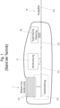
- a printer for printing marker cards 2 with markers 3 for marking electrical devices, connectors, cables or the like is shown according to the prior art.
- the handling of the marker card 2 in the printer according to the prior art takes place in a line, i.e. without changing the direction of the marker card during handling.
- the printer has various devices I, II, III, IV, each device being assigned a defined function.
- the first device I has a magazine with a separating device. It is a separating device.
- a printing device - a previously separated marker card 2 is printed.
- a fixing device - the print image is fixed on the printed marker card 2.
- an output device - the finished printed marker card 2 is output.
- a cooling zone may be integrated into the output device (not shown here).
- a device For transport within a printer with one or more devices according to the type of Fig.1 A device is used for handling printable marker cards 2 with markers 3 for marking electrical devices, connectors, cables or the like in a printing process of the printer.
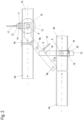
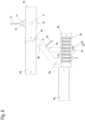
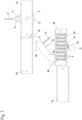
- Fig. 2 an exemplary device 1 according to the invention for handling printable marker cards 2 with markers 3 for marking electrical devices, connectors, cables or the like in a printing process of a printer is shown.
- the handling, in particular the conveying or transport, of the marker card 2 no longer takes place in a straight line, but with one or more changes in direction of the marker card during handling. Overall, this results in a non-straight conveying path when conveying the respective plate-like medium through the printer.
- the device 1 has several, here four, receiving and fixing devices, referred to below as stations 4a, 4b, 4c, 4d, for one or more consecutive marker cards 2 to be printed.
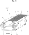
- stations 4a to 4d each have a Fig. 13 shown conveying means 23, with which the respective marker card 2 can be conveyed translationally from one station 4a to 4c to another station 4b to 4d.
- the conveyor 23 is designed here as a round belt conveyor with two parallel, synchronously driven round belts 24.
- other conveyors 23 are also possible, such as a belt conveyor or a roller conveyor.
- the stations 4a to 4d can be designed as a kind of shell 25 with a U-shaped cross-section (see also Fig. 13 ). They can each be assigned a functional device I, II, III, IV, such as a printing device or a fixing device.
- the marker card 2a has U-profiles 26 arranged laterally and formed as a single piece, which touch the respective round belt 24 of the conveyor 23 on three sides and are supported on the respective round belt 24.
- the stations 4a to 4d can each have sliding plates 27.
- the sliding plates 27 serve to guide the marker cards 2 in a vertical direction, whereby "vertical” refers to the drawing plane of the Fig. 13 In this way, the marker card 2 is reliably guided in one plane during conveying.
- the first station 4a can be installed in a fixed location and can be designed as a magazine with a separating device as a functional device (otherwise not shown here). It can therefore also form part of the separating device.
- the second station 4b can be provided as a clamping and feed device for the printing device and thus form part of a printing device as a functional device (otherwise not shown here). This can also form a type of switch.
- the second station 4b is pivotally mounted by a first pivot bearing 5.
- the first station 4a and the second station 4b are arranged one behind the other in a line, with the second station 4b leaving this line in a parallel shift during the subsequent printing process in order to orient the marker card 2a accordingly to a print head. After printing is complete, a pivoting movement can also be provoked using the same drive.
- the third station 4c can also be provided as a switch and is therefore pivotably mounted by a second pivot bearing 6, similar to the second station 4b.
- the fourth station 4d is stationary. It can form part of a fixing device as a functional device in which the printed image is fixed on the markers 3, e.g. by supplying heat.
- the third station 4c and the fourth station 4d are arranged one behind the other in a straight line, wherein the third station 4c can be pivoted via the second pivot bearing 6 from this line at an angle oblique thereto from a first pivot position into a second pivot position oblique thereto.
- the second station 4b and the third station 4c can, if required, be brought into line via the respective first pivot bearing 5 and the second pivot bearing 6 and a drive.
- a U-shaped conveying direction is therefore realized for the marker card 2 to be printed or for the printed marker card 2 in the printing process - in other words, here, for example, a conveying direction with two changes of direction.
- the device 1 can also be designed in such a way that it can be used to achieve a single change in direction, i.e. for example an angular - for example L-shaped - conveying direction is achieved.
- the conveying means 23 are designed in such a way that it can achieve a conveying direction with more than two changes of direction - e.g. an S-shaped conveying direction is realized.
- the conveying direction with at least one change of direction results in an advantageous higher printing performance of the entire printing process of the printer.
- the device 1 can have a pivoting plate 7 which is positioned between the second station 4b and the third station 4c.
- the pivoting plate 7 has an elongated stop section 7a which extends in relation to the drawing plane of the Fig. 2 diagonally at an angle between the second station 4b and the third station 4c.
- the stop section 7a can have several pivoting plates 7 perpendicular to the plane of the drawing of the Fig. 2 have protruding stops 8a, 8b, 8c.
- the stops 8a, 8b, 8c can be firmly connected to the stop section 7a of the pivoting plate 7 and can also pass through the stop section 7a.
- the stop section 7a can also have a web 9 which is provided with a hole through which an eyelet of a first spring 10 passes. An eyelet at another end of the first spring 10 is suspended in a fixed part not shown in detail here.
- the first spring 10 is designed here as a helical tension spring.
- the stop section 7a has a further stop 16, which is positioned laterally on the stop section 7a.
- the pivot plate 7 can also have a bearing section 7b.
- the bearing section 7b accommodates a fixed bearing pin of the second pivot bearing 6 of the third station 4c.
- the bearing section 7b has a holding plate 11 coaxial with the second pivot bearing 6.
- a first drive which is designed here as a motor 12, is attached to the holding plate 11 in a rotationally fixed manner.
- the motor 12 can initiate a pivoting movement of the third station 4c via a gear transmission.
- the holding plate 11 has a second spring 17, which serves as a return spring for the motor 12.
- the second spring 17 is designed here as a spiral tension spring.
- the spring can also be designed differently, such as as a spiral compression spring; a springy return function is essential.
- the holding plate 11 is rotatably mounted coaxially to the second pivot bearing 6.
- a gear 13 is connected to the station 4c in a rotationally fixed manner, which meshes with a pinion 14 driven by the motor 12, thus forming the gear transmission.
- the design of the transmission as a gear transmission is advantageous, but not mandatory.
- the transmission can therefore also be designed differently, for example as a belt transmission or coupling transmission.
- a direct drive of the swivel movement of the station 4c by the motor 12 is also possible.
- the motor 12 can also be designed as a gear motor.
- a guide rail 15 serves as a straight guide for the translational displacement of the second station 4b vertically upwards, whereby “vertically upwards” refers to the drawing plane of the Fig. 2
- the guide rail 15 has a guide carriage 18.
- the guide carriage 18 is movably guided on the guide rail 15 and has a fixed bearing pin of the first pivot bearing 5, by means of which the second station 4b is pivotally mounted on the guide carriage 18.
- the second station 4b has a web 19.
- the web 19 has a hole through which an eyelet of a third spring 20 passes.
- the third spring 20 is designed as a spiral tension spring.
- An eyelet at another end of the third spring 20 is connected to the guide carriage 18.
- the third spring 20 serves as a return spring for the second station 4b when it is pivoted out about the first pivot bearing 5. This is one possible design for a return mechanism with a stop. Other structural designs or other geometric arrangements are also possible.
- the third station 4c has a stop 21 which is supported on the outside of the fourth station 4d and is positioned in such a way that a pivoting of the third station 4c in an anti-clockwise direction is prevented.
- This is a possible Design for the stop.
- Other structural designs or other geometric arrangements are also possible.
- the third station 4c has a recess 22.
- the recess 22 ensures that the third station 4c can assume a position in line with the fourth station 4d despite the stop 8c, which is positioned on the stop section 7a of the pivoting plate 7 in the region of a free end of the third station 4c, which is in line with the fourth station 4d, in such a way that it would prevent this without the recess 22.
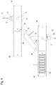
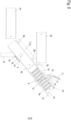
- Fig.3 the device 1 is shown in a three-dimensional view.
- the stops 8a, 8b, 8c on the stop section 7a of the swivel plate 7 are clearly visible.
- the webs 9 and 19 as well as the stop 22 and the recess 22 are also clearly visible.
- a first marker card 2a has been separated from a magazine into the first station 4a of the device 1 with the separating device.
- the marker card 2 is in a flat-horizontal orientation in the first station 4a.
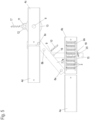
- Fig.4 shown.
- the first marker card 2a was conveyed centrally and symmetrically to the second station 2b by the respective conveyor 23 of the first station 4a and the second station 4b and thus fed to the printing area of the printer (not shown here), so that the first marker card 2a can be printed.
- the first marker card 2a is in the printing position and is printed.
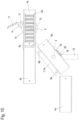
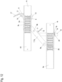
- Fig.7 the printing process is completed and the second station 4b with the first printed marker card 2a is in relation to the drawing plane of the Fig.7 with the guide carriage 18 along the guide rail 15 vertically upwards in the direction of the swivel plate 7 until the second station 4b contacts the first stop 8a of the swivel plate 7.
- Fig.8 is the second station 4b in relation to the drawing plane of the Fig.8 with the guide carriage 18 along the guide rail 15 further vertically upwards in the direction of the swivel plate 7, so that the second station 4b additionally contacts the second stop 8b of the swivel plate 7.
- the station 4b performs a pivoting movement around a central axis of the first pivot bearing 5 in an anti-clockwise direction, since the direction of movement of the guide carriage 18 and the first stop 8a forms a force couple that generates a torque that rotates around an instantaneous center that coincides with a circumferential line of the first stop 8a and acts on the second station 4b.
- Both movements - namely the vertical movement of the station 4b along the guide rail 15 and the pivoting movement of the station 4b around the central axis of the first pivot bearing 5 in the counterclockwise direction - can advantageously be actuated by a single second drive (not shown here).
- both the second station 4b and the pivoting plate 7 are inevitably aligned parallel to one another, even if the second station 4b is moved further vertically upwards along the guide rail 15, for example in order to compensate for potential tolerances between the components.
- the third station 4c also carries out a pivoting movement driven by the motor 12 via the pinion 14 and the gear 13. A counter torque to the torque of the motor 12 is applied by the second spring 17. In this case, a pivoting movement is carried out in a clockwise direction around a central axis of the second pivot bearing 6 until the third station 4c contacts the third stop 8c.
- the stops 8a, 8b, 8c are arranged in a line and the swivel plate can only move around the central axis of the second swivel bearing 6, which is also the swivel axis of the station 4c, the first station 4b and the second station 4c are necessarily and repeatedly aligned with each other after reaching the respective stops 8a, 8b or 8c.
- the motor 12 remains switched on for a certain time and deflects the second spring 17, since the third station 4c cannot be swiveled any further. Since the motor 12 is designed in such a way that its holding torque in the de-energized state is greater than the counter torque applied by the second spring 17, the station 4c always contacts the third stop 4c with a spring load.
- the motor 12 can also be a motor with an active holding torque, such as a stepper motor.
- the swivel and stop system of the two stations 4b and 4c compensates for tolerances with regard to mechanical and control-related influences.
- the two stations 4b and 4c advantageously come to a precise stop at the stops 8a and 8b or 8c, although the drives each stop gently.
- Fig.10 the situation is shown in which the third station 4c was swiveled back to its starting position - i.e. aligned or in line with the fourth station 4d. To do this, the motor 12 was set in a reversing movement until the third station 4c contacted the stop 21 again.
- the first marker card 2a can be conveyed further into the fixing area or into the fourth station 4d, while a second marker card 2b has already been separated into the first station 4a, as shown in Fig. 11 is recognizable.
- Fig. 12 it is shown how - after the first marker card 2a has been transferred to the third station 4c and pivoted with the third station 4c - the first marker card 2a is conveyed to the fourth station 4d - the output station - and the second marker card 2b is simultaneously conveyed from the first station 4a to the second station 4b - i.e. into the printing position.
- the printer's entire printing process advantageously improves printing performance.
Landscapes
- Engineering & Computer Science (AREA)
- Manufacturing & Machinery (AREA)
- Handling Of Cut Paper (AREA)
- Handling Of Sheets (AREA)
- Delivering By Means Of Belts And Rollers (AREA)
- Separation, Sorting, Adjustment, Or Bending Of Sheets To Be Conveyed (AREA)
Applications Claiming Priority (2)
| Application Number | Priority Date | Filing Date | Title |
|---|---|---|---|
| DE102019104934 | 2019-02-27 | ||
| PCT/EP2020/055057 WO2020174017A1 (de) | 2019-02-27 | 2020-02-26 | Drucker zum bedrucken von markierer-karten mit markierern zum markieren elektrischer geräte |
Publications (2)
| Publication Number | Publication Date |
|---|---|
| EP3931817A1 EP3931817A1 (de) | 2022-01-05 |
| EP3931817B1 true EP3931817B1 (de) | 2024-05-22 |
Family
ID=69770872
Family Applications (1)
| Application Number | Title | Priority Date | Filing Date |
|---|---|---|---|
| EP20709515.9A Active EP3931817B1 (de) | 2019-02-27 | 2020-02-26 | Drucker zum bedrucken von markierer-karten mit markierern zum markieren elektrischer geräte |
Country Status (10)
| Country | Link |
|---|---|
| US (1) | US11945241B2 (pl) |
| EP (1) | EP3931817B1 (pl) |
| CN (1) | CN113661534B (pl) |
| AU (1) | AU2020227214B2 (pl) |
| CA (1) | CA3127583A1 (pl) |
| DE (1) | DE102020105062A1 (pl) |
| ES (1) | ES2992807T3 (pl) |
| PL (1) | PL3931817T3 (pl) |
| WO (1) | WO2020174017A1 (pl) |
| ZA (1) | ZA202104997B (pl) |
Families Citing this family (3)
| Publication number | Priority date | Publication date | Assignee | Title |
|---|---|---|---|---|
| DE102022213235A1 (de) | 2022-12-07 | 2024-06-13 | Phoenix Contact Gmbh & Co. Kg | Transportvorrichtung zum Transportieren von Substraten |
| DE102022132564A1 (de) | 2022-12-07 | 2024-06-13 | Phoenix Contact Gmbh & Co. Kg | Transportvorrichtung für Substrate mit bewegbaren Niederhaltern |
| EP4630251A1 (de) | 2022-12-07 | 2025-10-15 | Phoenix Contact GmbH & Co KG | Transportvorrichtung für substrate mit bewegbaren niederhaltern |
Family Cites Families (18)
| Publication number | Priority date | Publication date | Assignee | Title |
|---|---|---|---|---|
| JP3366791B2 (ja) | 1995-11-09 | 2003-01-14 | ニスカ株式会社 | 情報記録装置 |
| US5814796A (en) * | 1996-01-31 | 1998-09-29 | Mag-Tek, Inc. | Terminal for issuing and processing data-bearing documents |
| WO2006044363A2 (en) | 2004-10-12 | 2006-04-27 | Jcm American Corporation | Gaming system card reader/writer/dispenser having provision for card recycling |
| DE102006003056B4 (de) * | 2006-01-20 | 2014-05-08 | Phoenix Contact Gmbh & Co. Kg | Tintendrucker zum Bedrucken von Gegenständen |
| DE202006005458U1 (de) | 2006-04-04 | 2007-08-16 | Weidmüller Interface GmbH & Co. KG | Drucker und Druckmedium, insbesondere Karte oder Markierer |
| ITGE20060081A1 (it) | 2006-08-03 | 2008-02-04 | Grafoplast Spa | Dispositivo automatico di carico/scarico di supporti di stampa in una macchina da stampa. |
| CN101625810B (zh) * | 2008-07-07 | 2013-09-04 | 约翰·谢尔勒鲁普 | 用于防止未经许可取走商品的安全系统 |
| JP2011116466A (ja) | 2009-11-30 | 2011-06-16 | Nisca Corp | 搬送ベルトおよび印刷装置 |
| CN102029808B (zh) * | 2009-09-30 | 2014-11-19 | 立志凯株式会社 | 印刷装置以及输送带 |
| DE102010051539A1 (de) | 2010-11-18 | 2012-05-24 | Murrplastik Systemtechnik Gmbh | Vorrichtung zur Beschriftung von Kennzeichnungsschildern |
| DE202012101998U1 (de) | 2012-05-31 | 2013-09-02 | Weidmüller Interface GmbH & Co. KG | Drucker mit einer Vereinzelungsvorrichtung |
| US8976409B2 (en) | 2013-03-14 | 2015-03-10 | Xerox Corporation | Large sheet image on paper registration |
| DE102013104780A1 (de) | 2013-05-08 | 2014-11-13 | Weidmüller Interface GmbH & Co. KG | Magaziniervorrichtung und Verfahren zum Aufstapeln von bedruckten Markierungselementmatten |
| DE102013018196A1 (de) | 2013-10-30 | 2015-04-30 | Murrplastik Systemtechnik Gmbh | Vorrichtung zum Greifen und Transportieren eines Kennzeichnungsschildersatzes |
| DE102014004365B4 (de) | 2014-03-26 | 2016-11-03 | Phoenix Contact Gmbh & Co. Kg | Markierungsvorrichtung |
| DE102014012055A1 (de) | 2014-08-18 | 2016-02-18 | Murrplastik Systemtechnik Gmbh | Vorrichtung zur Beschriftung von Kennzeichnungseinheiten |
| IT201600126141A1 (it) | 2016-12-14 | 2018-06-14 | Danilo Rigardo | Dispositivo di trascinamento di targhette di identificazione per cavi e componenti elettrici al fine di ottenerne la stampa a mezzo di una stampante a getto di inchiostro e metodo per la realizzazione di un caricatore automatico. |
| CN107284040B (zh) * | 2017-06-05 | 2018-12-18 | 沈阳友联电子装备有限公司 | 一种ic卡激光打标方法及打标装置 |
-
2020
- 2020-02-26 US US17/427,360 patent/US11945241B2/en active Active
- 2020-02-26 CA CA3127583A patent/CA3127583A1/en active Pending
- 2020-02-26 WO PCT/EP2020/055057 patent/WO2020174017A1/de not_active Ceased
- 2020-02-26 DE DE102020105062.3A patent/DE102020105062A1/de active Pending
- 2020-02-26 PL PL20709515.9T patent/PL3931817T3/pl unknown
- 2020-02-26 ES ES20709515T patent/ES2992807T3/es active Active
- 2020-02-26 EP EP20709515.9A patent/EP3931817B1/de active Active
- 2020-02-26 AU AU2020227214A patent/AU2020227214B2/en active Active
- 2020-02-26 CN CN202080023067.0A patent/CN113661534B/zh active Active
-
2021
- 2021-07-15 ZA ZA2021/04997A patent/ZA202104997B/en unknown
Also Published As
| Publication number | Publication date |
|---|---|
| US20220143989A1 (en) | 2022-05-12 |
| CA3127583A1 (en) | 2020-09-03 |
| CN113661534B (zh) | 2023-08-18 |
| US11945241B2 (en) | 2024-04-02 |
| CN113661534A (zh) | 2021-11-16 |
| ZA202104997B (en) | 2022-07-27 |
| DE102020105062A1 (de) | 2020-08-27 |
| WO2020174017A1 (de) | 2020-09-03 |
| PL3931817T3 (pl) | 2024-09-09 |
| EP3931817A1 (de) | 2022-01-05 |
| AU2020227214A1 (en) | 2021-08-12 |
| AU2020227214B2 (en) | 2025-09-11 |
| ES2992807T3 (en) | 2024-12-18 |
Similar Documents
| Publication | Publication Date | Title |
|---|---|---|
| EP0052408B1 (de) | Schreibwerk mit einem Aufzeichnungsorgan und Mitteln zum Umlenken eines Aufzeichnungsträgers | |
| EP3931817B1 (de) | Drucker zum bedrucken von markierer-karten mit markierern zum markieren elektrischer geräte | |
| CH620652A5 (pl) | ||
| DE3736878C2 (pl) | ||
| EP2751744B1 (de) | Wendevorrichtung für identifikationsgegenstände | |
| EP0576390A1 (de) | Vorrichtung zum Sammeln von Einzelblättern zu einem Bund | |
| DE2618439C2 (de) | Transporteinrichtung für die Auswertung von Identifizierungskarten | |
| EP2855311B1 (de) | Drucker mit einer vereinzelungsvorrichtung | |
| DE2717758C3 (de) | Vorrichtung zur Papierführung in Druckgeräten, insbesondere bei Daten- und Fernschreibmaschinen | |
| AT501863A1 (de) | Haltevorrichtung für tintenstrahldrucker | |
| DE1243428B (de) | Aufzeichnungstraeger-Entnahmevorrichtung | |
| DE102010048921A1 (de) | Verfahren und Einrichtung zum Erfassen und Bedrucken von Dokumenten | |
| EP1882659A2 (de) | Bogenstanz- und -prägemaschine und Verfahren zur Bogenausrichtung | |
| BE1031113B1 (de) | Aufstaplungsvorrichtung zum Aufstapeln von Substraten | |
| DE2047669C3 (de) | Steuereinrichtung zum Auswählen der einen von zwei Transportgeschwindigkeiten bei Karten- oder Streifenlochern | |
| DE2913595A1 (de) | Transportvorrichtung fuer blattfoermige aufzeichnungstraeger | |
| WO2024120780A1 (de) | Aufstaplungsvorrichtung zum aufstapeln von substraten | |
| DE2002313C3 (de) | Vorsteckeinrichtung an Schreib , Buchungs und ähnlichen Maschinen | |
| DE2606697B2 (de) | Vorrichtung zum Vereinzeln von Aufzeichnungsträgern | |
| DE3031992C2 (pl) | ||
| EP3296114A1 (de) | Drucker mit auszugssystem für ein druckmodul | |
| DE1810940C (de) | Vorsteckeinrichtung an Schreib-, Buchungs- und ähnlichen Maschinen | |
| EP4630251A1 (de) | Transportvorrichtung für substrate mit bewegbaren niederhaltern | |
| EP4630355A1 (de) | Vereinzelungsvorrichtung zum vereinzeln aufgestapelter substrate | |
| DE102023105409A1 (de) | Vereinzelungsvorrichtung zum Vereinzeln aufgestapelter Substrate |
Legal Events
| Date | Code | Title | Description |
|---|---|---|---|
| STAA | Information on the status of an ep patent application or granted ep patent |
Free format text: STATUS: UNKNOWN |
|
| STAA | Information on the status of an ep patent application or granted ep patent |
Free format text: STATUS: THE INTERNATIONAL PUBLICATION HAS BEEN MADE |
|
| PUAI | Public reference made under article 153(3) epc to a published international application that has entered the european phase |
Free format text: ORIGINAL CODE: 0009012 |
|
| STAA | Information on the status of an ep patent application or granted ep patent |
Free format text: STATUS: REQUEST FOR EXAMINATION WAS MADE |
|
| 17P | Request for examination filed |
Effective date: 20210913 |
|
| AK | Designated contracting states |
Kind code of ref document: A1 Designated state(s): AL AT BE BG CH CY CZ DE DK EE ES FI FR GB GR HR HU IE IS IT LI LT LU LV MC MK MT NL NO PL PT RO RS SE SI SK SM TR |
|
| DAV | Request for validation of the european patent (deleted) | ||
| DAX | Request for extension of the european patent (deleted) | ||
| GRAP | Despatch of communication of intention to grant a patent |
Free format text: ORIGINAL CODE: EPIDOSNIGR1 |
|
| STAA | Information on the status of an ep patent application or granted ep patent |
Free format text: STATUS: GRANT OF PATENT IS INTENDED |
|
| INTG | Intention to grant announced |
Effective date: 20240109 |
|
| GRAS | Grant fee paid |
Free format text: ORIGINAL CODE: EPIDOSNIGR3 |
|
| P01 | Opt-out of the competence of the unified patent court (upc) registered |
Effective date: 20240307 |
|
| GRAA | (expected) grant |
Free format text: ORIGINAL CODE: 0009210 |
|
| STAA | Information on the status of an ep patent application or granted ep patent |
Free format text: STATUS: THE PATENT HAS BEEN GRANTED |
|
| AK | Designated contracting states |
Kind code of ref document: B1 Designated state(s): AL AT BE BG CH CY CZ DE DK EE ES FI FR GB GR HR HU IE IS IT LI LT LU LV MC MK MT NL NO PL PT RO RS SE SI SK SM TR |
|
| REG | Reference to a national code |
Ref country code: GB Ref legal event code: FG4D Free format text: NOT ENGLISH |
|
| REG | Reference to a national code |
Ref country code: CH Ref legal event code: EP |
|
| REG | Reference to a national code |
Ref country code: DE Ref legal event code: R096 Ref document number: 502020008063 Country of ref document: DE |
|
| REG | Reference to a national code |
Ref country code: IE Ref legal event code: FG4D Free format text: LANGUAGE OF EP DOCUMENT: GERMAN |
|
| REG | Reference to a national code |
Ref country code: NL Ref legal event code: FP |
|
| REG | Reference to a national code |
Ref country code: SE Ref legal event code: TRGR |
|
| REG | Reference to a national code |
Ref country code: LT Ref legal event code: MG9D |
|
| PG25 | Lapsed in a contracting state [announced via postgrant information from national office to epo] |
Ref country code: IS Free format text: LAPSE BECAUSE OF FAILURE TO SUBMIT A TRANSLATION OF THE DESCRIPTION OR TO PAY THE FEE WITHIN THE PRESCRIBED TIME-LIMIT Effective date: 20240922 |
|
| PG25 | Lapsed in a contracting state [announced via postgrant information from national office to epo] |
Ref country code: BG Free format text: LAPSE BECAUSE OF FAILURE TO SUBMIT A TRANSLATION OF THE DESCRIPTION OR TO PAY THE FEE WITHIN THE PRESCRIBED TIME-LIMIT Effective date: 20240522 |
|
| PG25 | Lapsed in a contracting state [announced via postgrant information from national office to epo] |
Ref country code: FI Free format text: LAPSE BECAUSE OF FAILURE TO SUBMIT A TRANSLATION OF THE DESCRIPTION OR TO PAY THE FEE WITHIN THE PRESCRIBED TIME-LIMIT Effective date: 20240522 Ref country code: HR Free format text: LAPSE BECAUSE OF FAILURE TO SUBMIT A TRANSLATION OF THE DESCRIPTION OR TO PAY THE FEE WITHIN THE PRESCRIBED TIME-LIMIT Effective date: 20240522 |
|
| PG25 | Lapsed in a contracting state [announced via postgrant information from national office to epo] |
Ref country code: GR Free format text: LAPSE BECAUSE OF FAILURE TO SUBMIT A TRANSLATION OF THE DESCRIPTION OR TO PAY THE FEE WITHIN THE PRESCRIBED TIME-LIMIT Effective date: 20240823 |
|
| PG25 | Lapsed in a contracting state [announced via postgrant information from national office to epo] |
Ref country code: PT Free format text: LAPSE BECAUSE OF FAILURE TO SUBMIT A TRANSLATION OF THE DESCRIPTION OR TO PAY THE FEE WITHIN THE PRESCRIBED TIME-LIMIT Effective date: 20240923 |
|
| PG25 | Lapsed in a contracting state [announced via postgrant information from national office to epo] |
Ref country code: LV Free format text: LAPSE BECAUSE OF FAILURE TO SUBMIT A TRANSLATION OF THE DESCRIPTION OR TO PAY THE FEE WITHIN THE PRESCRIBED TIME-LIMIT Effective date: 20240522 |
|
| PG25 | Lapsed in a contracting state [announced via postgrant information from national office to epo] |
Ref country code: PT Free format text: LAPSE BECAUSE OF FAILURE TO SUBMIT A TRANSLATION OF THE DESCRIPTION OR TO PAY THE FEE WITHIN THE PRESCRIBED TIME-LIMIT Effective date: 20240923 Ref country code: NO Free format text: LAPSE BECAUSE OF FAILURE TO SUBMIT A TRANSLATION OF THE DESCRIPTION OR TO PAY THE FEE WITHIN THE PRESCRIBED TIME-LIMIT Effective date: 20240822 Ref country code: LV Free format text: LAPSE BECAUSE OF FAILURE TO SUBMIT A TRANSLATION OF THE DESCRIPTION OR TO PAY THE FEE WITHIN THE PRESCRIBED TIME-LIMIT Effective date: 20240522 Ref country code: IS Free format text: LAPSE BECAUSE OF FAILURE TO SUBMIT A TRANSLATION OF THE DESCRIPTION OR TO PAY THE FEE WITHIN THE PRESCRIBED TIME-LIMIT Effective date: 20240922 Ref country code: HR Free format text: LAPSE BECAUSE OF FAILURE TO SUBMIT A TRANSLATION OF THE DESCRIPTION OR TO PAY THE FEE WITHIN THE PRESCRIBED TIME-LIMIT Effective date: 20240522 Ref country code: GR Free format text: LAPSE BECAUSE OF FAILURE TO SUBMIT A TRANSLATION OF THE DESCRIPTION OR TO PAY THE FEE WITHIN THE PRESCRIBED TIME-LIMIT Effective date: 20240823 Ref country code: FI Free format text: LAPSE BECAUSE OF FAILURE TO SUBMIT A TRANSLATION OF THE DESCRIPTION OR TO PAY THE FEE WITHIN THE PRESCRIBED TIME-LIMIT Effective date: 20240522 Ref country code: BG Free format text: LAPSE BECAUSE OF FAILURE TO SUBMIT A TRANSLATION OF THE DESCRIPTION OR TO PAY THE FEE WITHIN THE PRESCRIBED TIME-LIMIT Effective date: 20240522 Ref country code: RS Free format text: LAPSE BECAUSE OF FAILURE TO SUBMIT A TRANSLATION OF THE DESCRIPTION OR TO PAY THE FEE WITHIN THE PRESCRIBED TIME-LIMIT Effective date: 20240822 |
|
| REG | Reference to a national code |
Ref country code: ES Ref legal event code: FG2A Ref document number: 2992807 Country of ref document: ES Kind code of ref document: T3 Effective date: 20241218 |
|
| PG25 | Lapsed in a contracting state [announced via postgrant information from national office to epo] |
Ref country code: DK Free format text: LAPSE BECAUSE OF FAILURE TO SUBMIT A TRANSLATION OF THE DESCRIPTION OR TO PAY THE FEE WITHIN THE PRESCRIBED TIME-LIMIT Effective date: 20240522 |
|
| PG25 | Lapsed in a contracting state [announced via postgrant information from national office to epo] |
Ref country code: EE Free format text: LAPSE BECAUSE OF FAILURE TO SUBMIT A TRANSLATION OF THE DESCRIPTION OR TO PAY THE FEE WITHIN THE PRESCRIBED TIME-LIMIT Effective date: 20240522 |
|
| PG25 | Lapsed in a contracting state [announced via postgrant information from national office to epo] |
Ref country code: SK Free format text: LAPSE BECAUSE OF FAILURE TO SUBMIT A TRANSLATION OF THE DESCRIPTION OR TO PAY THE FEE WITHIN THE PRESCRIBED TIME-LIMIT Effective date: 20240522 Ref country code: RO Free format text: LAPSE BECAUSE OF FAILURE TO SUBMIT A TRANSLATION OF THE DESCRIPTION OR TO PAY THE FEE WITHIN THE PRESCRIBED TIME-LIMIT Effective date: 20240522 |
|
| PG25 | Lapsed in a contracting state [announced via postgrant information from national office to epo] |
Ref country code: SM Free format text: LAPSE BECAUSE OF FAILURE TO SUBMIT A TRANSLATION OF THE DESCRIPTION OR TO PAY THE FEE WITHIN THE PRESCRIBED TIME-LIMIT Effective date: 20240522 |
|
| PG25 | Lapsed in a contracting state [announced via postgrant information from national office to epo] |
Ref country code: SM Free format text: LAPSE BECAUSE OF FAILURE TO SUBMIT A TRANSLATION OF THE DESCRIPTION OR TO PAY THE FEE WITHIN THE PRESCRIBED TIME-LIMIT Effective date: 20240522 Ref country code: SK Free format text: LAPSE BECAUSE OF FAILURE TO SUBMIT A TRANSLATION OF THE DESCRIPTION OR TO PAY THE FEE WITHIN THE PRESCRIBED TIME-LIMIT Effective date: 20240522 Ref country code: RO Free format text: LAPSE BECAUSE OF FAILURE TO SUBMIT A TRANSLATION OF THE DESCRIPTION OR TO PAY THE FEE WITHIN THE PRESCRIBED TIME-LIMIT Effective date: 20240522 Ref country code: EE Free format text: LAPSE BECAUSE OF FAILURE TO SUBMIT A TRANSLATION OF THE DESCRIPTION OR TO PAY THE FEE WITHIN THE PRESCRIBED TIME-LIMIT Effective date: 20240522 Ref country code: DK Free format text: LAPSE BECAUSE OF FAILURE TO SUBMIT A TRANSLATION OF THE DESCRIPTION OR TO PAY THE FEE WITHIN THE PRESCRIBED TIME-LIMIT Effective date: 20240522 |
|
| REG | Reference to a national code |
Ref country code: DE Ref legal event code: R097 Ref document number: 502020008063 Country of ref document: DE |
|
| PLBE | No opposition filed within time limit |
Free format text: ORIGINAL CODE: 0009261 |
|
| STAA | Information on the status of an ep patent application or granted ep patent |
Free format text: STATUS: NO OPPOSITION FILED WITHIN TIME LIMIT |
|
| PGFP | Annual fee paid to national office [announced via postgrant information from national office to epo] |
Ref country code: DE Payment date: 20250218 Year of fee payment: 6 |
|
| PGFP | Annual fee paid to national office [announced via postgrant information from national office to epo] |
Ref country code: SE Payment date: 20250218 Year of fee payment: 6 |
|
| PG25 | Lapsed in a contracting state [announced via postgrant information from national office to epo] |
Ref country code: SI Free format text: LAPSE BECAUSE OF FAILURE TO SUBMIT A TRANSLATION OF THE DESCRIPTION OR TO PAY THE FEE WITHIN THE PRESCRIBED TIME-LIMIT Effective date: 20240522 |
|
| PGFP | Annual fee paid to national office [announced via postgrant information from national office to epo] |
Ref country code: CH Payment date: 20250301 Year of fee payment: 6 |
|
| PGFP | Annual fee paid to national office [announced via postgrant information from national office to epo] |
Ref country code: FR Payment date: 20250224 Year of fee payment: 6 Ref country code: PL Payment date: 20250217 Year of fee payment: 6 Ref country code: CZ Payment date: 20250218 Year of fee payment: 6 |
|
| PGFP | Annual fee paid to national office [announced via postgrant information from national office to epo] |
Ref country code: IT Payment date: 20250224 Year of fee payment: 6 Ref country code: GB Payment date: 20250220 Year of fee payment: 6 |
|
| 26N | No opposition filed |
Effective date: 20250225 |
|
| PGFP | Annual fee paid to national office [announced via postgrant information from national office to epo] |
Ref country code: TR Payment date: 20250218 Year of fee payment: 6 |
|
| PGFP | Annual fee paid to national office [announced via postgrant information from national office to epo] |
Ref country code: ES Payment date: 20250331 Year of fee payment: 6 |
|
| PG25 | Lapsed in a contracting state [announced via postgrant information from national office to epo] |
Ref country code: MC Free format text: LAPSE BECAUSE OF FAILURE TO SUBMIT A TRANSLATION OF THE DESCRIPTION OR TO PAY THE FEE WITHIN THE PRESCRIBED TIME-LIMIT Effective date: 20240522 |
|
| REG | Reference to a national code |
Ref country code: NL Ref legal event code: MM Effective date: 20250301 |
|
| PG25 | Lapsed in a contracting state [announced via postgrant information from national office to epo] |
Ref country code: LU Free format text: LAPSE BECAUSE OF NON-PAYMENT OF DUE FEES Effective date: 20250226 |
|
| PG25 | Lapsed in a contracting state [announced via postgrant information from national office to epo] |
Ref country code: NL Free format text: LAPSE BECAUSE OF NON-PAYMENT OF DUE FEES Effective date: 20250301 |