EP3931413B1 - Anchoring device for anchoring a stake of a beach parasol in sand or sandy soil - Google Patents
Anchoring device for anchoring a stake of a beach parasol in sand or sandy soil Download PDFInfo
- Publication number
- EP3931413B1 EP3931413B1 EP20706737.2A EP20706737A EP3931413B1 EP 3931413 B1 EP3931413 B1 EP 3931413B1 EP 20706737 A EP20706737 A EP 20706737A EP 3931413 B1 EP3931413 B1 EP 3931413B1
- Authority
- EP
- European Patent Office
- Prior art keywords
- wall
- plate
- sleeve
- anchoring device
- buriable
- Prior art date
- Legal status (The legal status is an assumption and is not a legal conclusion. Google has not performed a legal analysis and makes no representation as to the accuracy of the status listed.)
- Active
Links
- 239000004576 sand Substances 0.000 title claims description 47
- 238000004873 anchoring Methods 0.000 title claims description 32
- 239000002689 soil Substances 0.000 title claims description 8
- 239000000463 material Substances 0.000 claims description 10
- 229920001971 elastomer Polymers 0.000 claims description 8
- 238000004519 manufacturing process Methods 0.000 claims description 8
- 239000000806 elastomer Substances 0.000 claims description 6
- 238000000465 moulding Methods 0.000 claims description 5
- 238000000034 method Methods 0.000 claims description 4
- 239000004744 fabric Substances 0.000 claims description 3
- 239000012528 membrane Substances 0.000 description 7
- 230000000694 effects Effects 0.000 description 6
- 238000003780 insertion Methods 0.000 description 4
- 230000037431 insertion Effects 0.000 description 4
- 229920002943 EPDM rubber Polymers 0.000 description 2
- 241001508691 Martes zibellina Species 0.000 description 2
- 238000005452 bending Methods 0.000 description 2
- 238000009933 burial Methods 0.000 description 2
- 239000000470 constituent Substances 0.000 description 2
- 239000004033 plastic Substances 0.000 description 2
- 229920000728 polyester Polymers 0.000 description 2
- 239000000243 solution Substances 0.000 description 2
- 239000004743 Polypropylene Substances 0.000 description 1
- 239000000853 adhesive Substances 0.000 description 1
- 230000001070 adhesive effect Effects 0.000 description 1
- 238000013459 approach Methods 0.000 description 1
- 238000009412 basement excavation Methods 0.000 description 1
- 238000006073 displacement reaction Methods 0.000 description 1
- 239000000835 fiber Substances 0.000 description 1
- 239000012530 fluid Substances 0.000 description 1
- 238000002347 injection Methods 0.000 description 1
- 239000007924 injection Substances 0.000 description 1
- 230000014759 maintenance of location Effects 0.000 description 1
- 150000002825 nitriles Chemical class 0.000 description 1
- -1 polypropylene Polymers 0.000 description 1
- 229920001155 polypropylene Polymers 0.000 description 1
- 229920001296 polysiloxane Polymers 0.000 description 1
- 230000003014 reinforcing effect Effects 0.000 description 1
- 238000000926 separation method Methods 0.000 description 1
- 230000001131 transforming effect Effects 0.000 description 1
- 239000002759 woven fabric Substances 0.000 description 1
Images


Classifications
-
- E—FIXED CONSTRUCTIONS
- E04—BUILDING
- E04H—BUILDINGS OR LIKE STRUCTURES FOR PARTICULAR PURPOSES; SWIMMING OR SPLASH BATHS OR POOLS; MASTS; FENCING; TENTS OR CANOPIES, IN GENERAL
- E04H12/00—Towers; Masts or poles; Chimney stacks; Water-towers; Methods of erecting such structures
- E04H12/22—Sockets or holders for poles or posts
- E04H12/2253—Mounting poles or posts to the holder
- E04H12/2261—Mounting poles or posts to the holder on a flat base
-
- A—HUMAN NECESSITIES
- A45—HAND OR TRAVELLING ARTICLES
- A45B—WALKING STICKS; UMBRELLAS; LADIES' OR LIKE FANS
- A45B25/00—Details of umbrellas
-
- A—HUMAN NECESSITIES
- A45—HAND OR TRAVELLING ARTICLES
- A45F—TRAVELLING OR CAMP EQUIPMENT: SACKS OR PACKS CARRIED ON THE BODY
- A45F3/00—Travelling or camp articles; Sacks or packs carried on the body
- A45F3/44—Article supports adapted to be stuck into the ground
-
- A—HUMAN NECESSITIES
- A45—HAND OR TRAVELLING ARTICLES
- A45B—WALKING STICKS; UMBRELLAS; LADIES' OR LIKE FANS
- A45B23/00—Other umbrellas
- A45B2023/0012—Ground supported umbrellas or sunshades on a single post, e.g. resting in or on a surface there below
-
- A—HUMAN NECESSITIES
- A45—HAND OR TRAVELLING ARTICLES
- A45B—WALKING STICKS; UMBRELLAS; LADIES' OR LIKE FANS
- A45B25/00—Details of umbrellas
- A45B2025/003—Accessories not covered by groups A45B25/24 - A45B25/30
Definitions
- the present invention relates to a device for anchoring in the sand or in sandy soil, a beach umbrella stake.
- this anchor for the parasol does not resist the action of the wind on the deployed canvas of the parasol. Indeed, the wind resistance of the open parasol is relatively high and all it takes is a violent gust to tear it from the sand and make it pick up speed, transforming it into a daunting projectile. Fatal accidents have occurred in recent years on French territory alone.
- a screw-on parasol base which consists of a cone surmounted by a tubular part equipped with a screw handle and a screw for tightening the tube constituting the parasol base.
- a helical thread is formed around the cone.
- the parasol base is screwed into the sand and the parasol pole is inserted into the tubular part and the pole is blocked by tightening the screw.
- the resistance to tearing of the parasol stake is improved, given the increased surface of the parasol base to be screwed in contact with the sand and the presence of the helical net, but remains however insufficient to retain it during a gust Wind.
- the support base includes a membrane and a mounting bracket.
- the membrane is disc-shaped, it is made of a woven fabric in PVC coated polyester yarn.
- the thickness of the membrane is 0.75 mm.
- the diameter of the disc is between 46 cm and 91 cm and ideally measures 60 cm.
- the mounting bracket includes an upper portion located on the upper side of the membrane and a lower portion located on the lower side of the membrane. The two parts are attached to each other or to the membrane.
- the mounting bracket is defined by a central tubular element through which there is an internal bore slightly larger than the diameter of the parasol stem and which is surrounded by an upper outer sleeve. This is fixed in the membrane by press fit, by a fixing or with an adhesive. It is made of rubber or plastic material, such as PVC.
- the upper outer sleeve is crossed by a thread in which a tightening screw makes it possible to block the stem of the parasol.
- a device for anchoring in the sand or in sandy soil, a stake for a beach umbrella, comprising a plate buried in sand made of a flexible or semi-rigid material, a sleeve intended to receive said stake, the sleeve being associated with said plate via a junction zone, the sleeve being open on both sides;
- the sleeve comprises a tubular inner wall connected to the outer wall via radial ribs, said radial ribs being extended towards the inside of the tubular inner wall to come into contact with the wall constituting the stake.
- the sleeve does not require any additional clamping device to retain the parasol pole.
- the anchor device is relatively inexpensive to manufacture.
- a tubular intermediate wall is formed between the outer wall and the tubular inner wall, the tubular intermediate wall being connected to the outer wall and to the tubular inner wall, via the radial ribs.
- the sleeve has, in front view, an outer wall in the shape of a truncated cone, the large base of which forms the junction with the buryable plate.
- This geometry of the sleeve gives it good mechanical strength and makes it possible to increase the pressure that the sand exerts around the sleeve when the anchoring device is buried.
- openings pass through the buryable plate at the level of the junction zone and radial folds delimit facets in the buryable plate in the form of angular sectors, from the sleeve to the periphery of the plate. buryable, at least one radial ply being secant with an opening.
- the openings provide flexibility in the junction area.
- the facets are thus less deformed by the inclination of the sleeve in a windy situation on the parasol. They can thus remain stable when they are kept trapped in the sand, which avoids the excavation of the buryable wall.
- the openings allow the folding of the facets in the extension of the sleeve.
- cells are formed on the upper face intended to be turned towards the top of the buryable plate.
- Studs are formed in the burial sand, which increases the pull-out resistance of the device and improves its operating safety.
- the underside of the buryable plate has a smooth appearance.
- the smooth underside provides a suction cup effect to the buryable plate with underlying wet sand.
- the buryable plate has, when it rests on a flat support, the geometry of a disc with a diameter of between 20 cm and 40 cm +/- 2 cm with a preferential value of 30 cm +/-2cm.
- the anchoring device is effective for the majority of beach umbrellas with an open canopy diameter of approximately 180 cm.
- the anchoring device includes a stake for a parasol.
- This set can accommodate a parasol pole.
- the anchoring device includes a parasol pole equipped with a fabric and a mechanism for deploying the latter.
- This set provides independent use of the parasol.
- a method of manufacturing an anchor device forms part of the invention.
- the anchoring device is manufactured by molding, the buryable plate as well as the said sleeve forming one and the same object manufactured in one piece.
- the molded anchor is ready for use. It is packaged to be offered for sale.
- the material chosen is an elastomer and whose hardness is between 60 and 90 ⁇ 8 IRHD, the thickness of the buryable plate being between 2 and 10 mm with a preferred value of 3 mm.
- a buryable plate is thus obtained which has sufficient rigidity and in particular when the buryable plate is defined by facets.
- the anchor device 100 presented on the Figs. 1, 2 and 3 , is intended to anchor, in a safe manner, the stake P constituting a parasol, in the sand of a beach or in sandy soil.
- It consists of a Pf buried plate, a Mn sleeve for receiving a P stake for a parasol.
- the buryable plate Pf is laid flat on a plane support N to simulate a burying situation.
- the buryable plate Pf in this situation preferably has the shape of a disc D so that the user of the anchoring device 100 does not have to choose its best operating orientation.
- the diameter of the disc D is between 20 cm and 40 cm +/-2 cm depending on the size of the beach umbrella with a preferential value practically equal to 30 cm +/- 2 cm, corresponding to the majority of beach umbrellas and whose diameter of the open canvas is approximately 180 cm.
- the planar buryable plate Pf is made of a flexible or preferably semi-rigid material, manually deformable but which does not undergo permanent deformation, in the register of normal use.
- the hardness of the elastomer is chosen between 60 to 90 ⁇ 8 IRHD.
- the elastomer is chosen in particular from nitrile, EPDM (abbreviation for ethylene-propylene-diene monomer), silicone, rubber.
- the elastomer chosen is preferably a regenerated polypropylene.
- a material well suited for the manufacture of this Pf plate is a flat sheet of elastomer with a thickness of between 2 mm and 10 mm. A value of 3 mm provides correct resistance and sufficient rigidity.
- the upper face of the buryable plate Pf which is intended to face upwards has cells V in order to be able to receive by molding a plurality of aggregates of grains of sand and thus increase the contact surface of said plate with the mass of sand located above her.
- its underside is smooth to provide a suction cup effect with an underlying wet sand.
- the cells V are radially aligned. They have a square geometry at the periphery of the burial plate and which evolves towards a rectangular geometry as it approaches the sleeve Mn and by delimiting between them separations of quasi-constant and relatively small thickness. A thousand cells are at least formed in the buryable plate Pf. In this way, a plurality of studs are formed by molding in the burying sand, which increases the resistance to tearing of the device and improves its operating safety. .
- the constituent material of the buryable plate Pf can incorporate a reinforcing weft T made, for example, of a plurality of crossed polyester fibers, to increase the resistance to tearing of the buryable plate Pf.
- the sleeve Mn is connected to the buryable plate Pf via a zone of a junction Zj.
- the sleeve Mn is erected perpendicularly on the upper face of the disc D and in the center thereof. It is intended to receive the part of a beach umbrella pole P which is normally intended to be driven into the ground.
- the anchor device 100 of the invention is made in an injection mold of a plastic material.
- the sleeve Mn thus forms an integral part of the anchoring device 100, that is to say that the buryable plate Pf as well as said sleeve Mn form a single and same object manufactured in a single piece.
- This embodiment is suitable for mass production.
- the sleeve Mn emerges on both sides. In front view, it has an outer wall Tc in the shape of a truncated cone Tc, the large base of which forms the junction Zj with the buryable plate Pf to provide it with good mechanical strength and increase the pressure of the sand around the sleeve Mn.
- the sleeve Mn is defined by a tubular inner wall Pt in which it is necessary to insert the stake of the parasol.
- the tubular inner wall Pt preferably has a cylindrical geometry, as shown in this Fig. 2 .
- this tubular inner wall Pt is connected to the outer wall Tc via a plurality of radial ribs Nv to accept the deformation of said tubular inner wall.
- tubular inner wall Pt can increase in size during stake insertion to accept diameter stakes of different diameters.
- a tubular intermediate wall Pti is formed between the outer wall Tc and the tubular inner wall Pt.
- This tubular intermediate wall Pti is connected to the outer wall Tc and to the tubular inner wall Pt, via the radial ribs Nv.
- the tubular intermediate wall Pti preferably has a cylindrical geometry, as shown in this Fig. 2 . The presence of this tubular intermediate wall Pti increases the stiffness of the tubular inner wall Pt.
- the radial ribs Nv are extended inside the tubular inner wall Pt and are sized to come into contact with the wall of the post P.
- These projecting parts of the ribs Nv inside the tubular inner wall Pt allow on the one hand, to facilitate the insertion of the stake by rotation in said tubular inner wall Pt by bending the projecting parts of said ribs and, on the other hand, to increase the tightening of the stake in the sleeve Mn by the relatively high pressure they exert on the wall of the post T.
- the user can turn the post P in the opposite direction in the tubular inner wall Pt to bring the projecting parts of the ribs Nv into a radial plane.
- openings Ov pass through the buryable plate Pf at the level of the junction zone Zj.
- Openings Ov are regularly distributed around the axis of the tubular intermediate wall Pt.
- radial folds Ir delimit in the buryable plate Pf facets in the form of angular sectors Sa, from the sleeve Mn to the periphery of the buryable plate Pf. At least one radial fold Ir intersects with an opening Ov.
- the facets Sa have a semi-rigid structure given the nature of the constituent material of the device 100 and given the thickness of said facets.
- Each radial ply Ir is formed by a groove of constant width dug into the thickness of the buryable wall Pf, from its upper face.
- the facets Sa thus articulated can then move to match the approximately flat relief of the sand on which said buryable wall rests.
- the facets Sa can fold around the sleeve Mn and in its extension to practically form an easily transportable cylinder.
- the anchoring device 100 can be delivered with a link, such as an elastic bracelet to keep said facets folded back.
- the V cells are formed only in the Sa facets.
- the cells are present on at least half of the surface of the Sa facets.
- the operation of the anchoring device 100 is as follows with reference to the Figs. 4 and 5 : We thread the end of a pole P of a parasol range in the inner tubular wall Pt of the sleeve Mn. The projecting parts of the radial ribs Nv then come into contact with the wall of the post P to retain it firmly in the sleeve Mn.
- the stake P can be turned in one direction in the sleeve Mn to bend the projecting parts of the radial ribs Nv.
- the end of the stake is threaded so that its tapered end protrudes from the sleeve Mn by at least ten centimeters.
- the adherence of the projecting parts of the radial ribs Nv to the tube constituting the stake T is sufficient to retain it because the pressure applied is relatively high.
- the tubular inner wall Pt as well as the tubular intermediate wall Pti can expand by longitudinally compressing the ribs Nv to accept a larger post.
- the thicknesses of the tubular inner wall Pt, of the tubular intermediate wall Pti, of the ribs Nv, the spacing between the tubular inner wall Pt and the tubular intermediate wall Pti, this tubular intermediate wall Pti and the outer wall Tc are calculated so that the sleeve Mn can accommodate and hold a T rod whose diameter is between 22 and 25 mm.
- the anchoring device 100 equipped with a stake P, is then ready to be used.
- the sand is dug at the location of the parasol to a depth of about twenty centimeters.
- the buryable wall Pf is opened and placed substantially flat on the uncovered surface of the sand, the facets Sa marrying the imperfect flatness of the sand and the buryable wall Pf is then buried, covering it with the sand B removed beforehand.
- the facets Sa of the disc D rest by their lower faces on the sand and the upper face of the buryable wall Pf is covered by a mass of sand B and which is embedded by molding in the cells V to increase the retention capacity of the sleeve in said mass of sand.
- the pole of the parasol is then mounted on the stake P anchored in the sand B.
- the stake P is thus held in the sleeve Mn secured to the buryable wall Pf which extends practically in a horizontal direction and which is held prisoner in a mass sand.
- a force F1 symbolizing the pressure of the wind on the parasol is exerted radially on the post P, the junction zone Zj is deformed, thanks to the presence of the openings Ov, under the effect of the torque exerted in the sleeve Mn by the stake P.
- the pressure exerted by the sand B on both sides of the disc D limits the deformation of the buried wall sand Pf.
- the relatively rigid geometry of the facets Sa remains stable in the sand B thanks to this flexible junction zone Zj.
- the geometry of the buried plate Pf consequently also remains stable under the constraint of the inclination of the sleeve Mn by the effect of the wind on the parasol.
- the lateral displacement of the buryable plate Pf is practically non-existent due to the relatively large surface of its two faces, upper and lower, in contact with the sand B.
- the mass of sand B located above the buryable plate Pf traps it.
- the buryable plate Pf is like taken in vice.
- sand enters the interstices present inside the sleeve Mn.
- sand can thus penetrate between the stake P and the tubular inner wall Pt, between this tubular inner wall Pt and the tubular intermediate wall Pti, between this tubular intermediate wall Pti and the outer wall Tc.
- the sand embedded in the sleeve Mn blocks the expansion of the tubular inner wall Pt and of the tubular intermediate wall Pti so that the tightening of the projecting parts of the ribs Nv on the wall of the post P is maintained in particular when the sleeve tilts under the effect of the wind on the parasol.
- the buryable plate When not in use, the buryable plate can be folded around the stake to facilitate its transport.
Description
La présente invention concerne un dispositif d'ancrage dans le sable ou dans un sol sablonneux, d'un piquet de parasol de plage.The present invention relates to a device for anchoring in the sand or in sandy soil, a beach umbrella stake.
Pour tenir un piquet de parasol dans le sable d'une plage, la solution la plus usitée consiste à planter dans le sable l'extrémité effilée d'un piquet de parasol et à l'enfoncer manuellement. On fixe ensuite le mât du parasol dans l'extrémité libre du piquet.To hold a parasol pole in the sand of a beach, the most common solution consists of planting the tapered end of a parasol pole in the sand and pushing it in manually. The pole of the parasol is then fixed in the free end of the stake.
Compte tenu de la nature fluide du sable, cet ancrage pour le parasol résiste mal à l'action du vent sur la toile déployée du parasol. En effet, la prise au vent du parasol ouvert est relativement importante et il suffit d'une violente rafale pour l'arracher du sable et lui faire prendre de la vitesse, le transformant en redoutable projectile. Des accidents mortels sont survenus ces dernières années sur le seul territoire français.Given the fluid nature of the sand, this anchor for the parasol does not resist the action of the wind on the deployed canvas of the parasol. Indeed, the wind resistance of the open parasol is relatively high and all it takes is a violent gust to tear it from the sand and make it pick up speed, transforming it into a formidable projectile. Fatal accidents have occurred in recent years on French territory alone.
On connaît également un pied de parasol à visser et qui est constitué d'un cône surmonté d'une partie tubulaire équipée d'une poignée de vissage et d'une vis de serrage du tube constitutif du pied de parasol. Un filet hélicoïdal est formé autour du cône. On visse le pied de parasol dans le sable et l'on insère le piquet du parasol dans la partie tubulaire et on bloque le piquet en serrant la vis. La résistance à l'arrachement du piquet de parasol est améliorée, compte tenu de la surface accrue du pied de parasol à visser en contact avec le sable et de la présence du filet hélicoïdal, mais demeure cependant insuffisante pour le retenir lors d'une bourrasque de vent.A screw-on parasol base is also known, which consists of a cone surmounted by a tubular part equipped with a screw handle and a screw for tightening the tube constituting the parasol base. A helical thread is formed around the cone. The parasol base is screwed into the sand and the parasol pole is inserted into the tubular part and the pole is blocked by tightening the screw. The resistance to tearing of the parasol stake is improved, given the increased surface of the parasol base to be screwed in contact with the sand and the presence of the helical net, but remains however insufficient to retain it during a gust Wind.
On connaît encore à la lecture du document
Le support de montage comprend une partie supérieure située sur le côté supérieur de la membrane et une partie inférieure située sur le côté inférieur de la membrane. Les deux parties sont fixées l'une à l'autre ou à la membrane.The mounting bracket includes an upper portion located on the upper side of the membrane and a lower portion located on the lower side of the membrane. The two parts are attached to each other or to the membrane.
Le support de montage est défini par un élément tubulaire central traversé d'un alésage interne un peu plus grand que le diamètre de la tige du parasol et qui est entouré par un manchon extérieur supérieur. Celui-ci est fixé dans la membrane par ajustement à force, par une fixation ou avec un adhésif. Il est fabriqué en caoutchouc ou en matière plastique, telle que du PVC. Le manchon extérieur supérieur est traversé d'un taraudage dans lequel une vis de serrage permet de bloquer la tige du parasol.The mounting bracket is defined by a central tubular element through which there is an internal bore slightly larger than the diameter of the parasol stem and which is surrounded by an upper outer sleeve. This is fixed in the membrane by press fit, by a fixing or with an adhesive. It is made of rubber or plastic material, such as PVC. The upper outer sleeve is crossed by a thread in which a tightening screw makes it possible to block the stem of the parasol.
Considérant cet état de fait, le demandeur a cherché une solution plus simple à utiliser et plus simple à fabriquer pour tenir un parasol dans le sable d'une plage ou dans un sol sablonneux.Considering this state of affairs, the applicant has sought a solution that is simpler to use and simpler to manufacture for holding a parasol in the sand of a beach or in sandy soil.
À cet effet est proposé un dispositif d'ancrage dans le sable ou dans un sol sablonneux, d'un piquet pour un parasol de plage, comprenant une plaque enfouis sable fabriquée dans un matériau souple ou semi-rigide, un manchon destiné à réceptionner ledit piquet, le manchon étant associé à ladite plaque par l'intermédiaire d'une zone de jonction, le manchon étant débouchant de ses deux côtés ; selon l'invention, le manchon comprend une paroi intérieure tubulaire reliée à la paroi extérieure par l'intermédiaire de nervures radiales, lesdites nervures radiales étant prolongées vers l'intérieur de la paroi intérieure tubulaire pour venir en contact avec la paroi constitutive du piquet.To this end, a device is proposed for anchoring in the sand or in sandy soil, a stake for a beach umbrella, comprising a plate buried in sand made of a flexible or semi-rigid material, a sleeve intended to receive said stake, the sleeve being associated with said plate via a junction zone, the sleeve being open on both sides; according to the invention, the sleeve comprises a tubular inner wall connected to the outer wall via radial ribs, said radial ribs being extended towards the inside of the tubular inner wall to come into contact with the wall constituting the stake.
Ces parties saillantes de nervures à l'intérieur de la paroi intérieure tubulaire permettent, d'une part, de faciliter l'insertion du piquet par rotation dans ladite paroi intérieure tubulaire en fléchissant les parties saillantes desdites nervures et, d'autre part, d'augmenter le serrage du piquet dans le manchon par la pression relativement élevée qu'elles exercent sur la paroi du piquet.These projecting parts of ribs inside the tubular inner wall make it possible, on the one hand, to facilitate the insertion of the stake by rotation in said tubular inner wall by bending the projecting parts of said ribs and, on the other hand, to increase the tightening of the post in the sleeve by the relatively high pressure they exert on the wall of the post.
Le manchon ne nécessite aucun dispositif de serrage annexe pour retenir le piquet de parasol. Le dispositif d'ancrage est relativement économique à fabriquer.The sleeve does not require any additional clamping device to retain the parasol pole. The anchor device is relatively inexpensive to manufacture.
Selon une autre caractéristique de l'invention, une paroi intermédiaire tubulaire est formée entre la paroi extérieure et la paroi intérieure tubulaire, la paroi intermédiaire tubulaire étant reliée à la paroi extérieure et à la paroi intérieure tubulaire, par l'intermédiaire des nervures radiales.According to another characteristic of the invention, a tubular intermediate wall is formed between the outer wall and the tubular inner wall, the tubular intermediate wall being connected to the outer wall and to the tubular inner wall, via the radial ribs.
La présence de cette paroi intermédiaire tubulaire augmente la raideur de la paroi intérieure tubulaire.The presence of this tubular intermediate wall increases the stiffness of the tubular inner wall.
Selon une autre caractéristique de l'invention, le manchon présente en vue de face une paroi extérieure en forme de tronc de cône et dont la grande base forme la jonction avec la plaque enfouissable.According to another characteristic of the invention, the sleeve has, in front view, an outer wall in the shape of a truncated cone, the large base of which forms the junction with the buryable plate.
Cette géométrie du manchon lui procure une bonne résistance mécanique et permet d'accroître la pression que le sable exerce autour du manchon quand le dispositif d'ancrage est enfoui.This geometry of the sleeve gives it good mechanical strength and makes it possible to increase the pressure that the sand exerts around the sleeve when the anchoring device is buried.
Selon une autre caractéristique de l'invention, des ouvertures traversent la plaque enfouissable au niveau de la zone de jonction et des plis radiaux délimitent dans la plaque enfouissable des facettes en forme de secteurs angulaires, depuis le manchon jusqu'à la périphérie de la plaque enfouissable, au moins un pli radial étant sécant avec une ouverture.According to another characteristic of the invention, openings pass through the buryable plate at the level of the junction zone and radial folds delimit facets in the buryable plate in the form of angular sectors, from the sleeve to the periphery of the plate. buryable, at least one radial ply being secant with an opening.
Les ouvertures apportent de la souplesse dans la zone de jonction.The openings provide flexibility in the junction area.
Les facettes sont ainsi moins déformées par l'inclinaison du manchon en situation de vent sur le parasol. Elles peuvent ainsi demeurer stables quand elles sont maintenues prisonnières dans le sable, ce qui évite le déchaussement de la paroi enfouissable.The facets are thus less deformed by the inclination of the sleeve in a windy situation on the parasol. They can thus remain stable when they are kept trapped in the sand, which avoids the excavation of the buryable wall.
Les ouvertures permettent le repliement des facettes dans le prolongement du manchon.The openings allow the folding of the facets in the extension of the sleeve.
Selon une autre caractéristique de l'invention, des alvéoles sont formées sur la face supérieure destinée à être tournée vers le haut de la plaque enfouissable.According to another characteristic of the invention, cells are formed on the upper face intended to be turned towards the top of the buryable plate.
Des plots sont formés dans le sable d'enfouissage, ce qui accroît la résistance à l'arrachement du dispositif et améliore sa sécurité de fonctionnement.Studs are formed in the burial sand, which increases the pull-out resistance of the device and improves its operating safety.
Selon une autre caractéristique de l'invention, la face inférieure de la plaque enfouissable présente un aspect lisse.According to another characteristic of the invention, the underside of the buryable plate has a smooth appearance.
La face inférieure lisse procure un effet ventouse à la plaque enfouissable avec un sable humide sous-jacent.The smooth underside provides a suction cup effect to the buryable plate with underlying wet sand.
Selon une autre caractéristique de l'invention, la plaque enfouissable présente, lorsqu'elle repose sur un appui plan, la géométrie d'un disque de diamètre compris entre 20 cm et 40 cm +/- 2 cm avec une valeur préférentielle de 30 cm +/-2 cm.According to another characteristic of the invention, the buryable plate has, when it rests on a flat support, the geometry of a disc with a diameter of between 20 cm and 40 cm +/- 2 cm with a preferential value of 30 cm +/-2cm.
Le dispositif d'ancrage est efficace pour la majorité des parasols de plage et dont le diamètre de la toile ouverte est d'environ 180 cm.The anchoring device is effective for the majority of beach umbrellas with an open canopy diameter of approximately 180 cm.
Selon une autre caractéristique de l'invention, le dispositif d'ancrage inclut un piquet pour un parasol.According to another characteristic of the invention, the anchoring device includes a stake for a parasol.
Cet ensemble permet d'accueillir un mât de parasol.This set can accommodate a parasol pole.
Avantageusement, le dispositif d'ancrage inclut un mât de parasol équipé d'une toile et d'un mécanisme de déploiement de celle-ci.Advantageously, the anchoring device includes a parasol pole equipped with a fabric and a mechanism for deploying the latter.
Cet ensemble procure une utilisation autonome du parasol.This set provides independent use of the parasol.
Un procédé de fabrication d'un dispositif d'ancrage fait partie de l'invention. Selon le procédé, le dispositif d'ancrage est fabriqué par moulage, la plaque enfouissable ainsi que ledit manchon formant un seul et même objet fabriqué d'un seul tenant.A method of manufacturing an anchor device forms part of the invention. According to the method, the anchoring device is manufactured by molding, the buryable plate as well as the said sleeve forming one and the same object manufactured in one piece.
Le dispositif d'ancrage fabriqué par moulage est prêt à être utilisé. Il est conditionné pour être proposé à la vente.The molded anchor is ready for use. It is packaged to be offered for sale.
Avantageusement, la matière choisie est un élastomère et dont la dureté est comprise entre 60 à 90 ± 8 IRHD, l'épaisseur de la plaque enfouissable étant comprise entre 2 et 10 mm avec une valeur préférentielle de 3 mm.Advantageously, the material chosen is an elastomer and whose hardness is between 60 and 90 ± 8 IRHD, the thickness of the buryable plate being between 2 and 10 mm with a preferred value of 3 mm.
On obtient ainsi une plaque enfouissable qui présente une rigidité suffisante et en particulier quand la plaque enfouissable est définie par des facettes.A buryable plate is thus obtained which has sufficient rigidity and in particular when the buryable plate is defined by facets.
Les caractéristiques de l'invention mentionnées ci-dessus, ainsi que d'autres, apparaîtront plus clairement à la lecture de la description suivante d'un exemple de réalisation, ladite description étant faite en relation avec les dessins joints, parmi lesquels :
- [
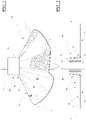
Fig 1 ] représente une vue en perspective d'un dispositif d'ancrage dans le sable, d'un piquet de parasol de plage selon l'invention, - [
Fig 2 ] représente une vue de face en coupe d'un dispositif d'ancrage dans le sable, d'un piquet de parasol de plage et dont la plaque enfouissable qui le constitue est mise à plat sur un plan en formant un disque selon l'invention, - [
Fig 3 ] représente une vue de dessus d'un dispositif d'ancrage d'un piquet de parasol de plage et dont la plaque enfouissable qui le constitue est ouverte en formant un disque selon l'invention, - [
Fig 4 ] représente une vue en coupe d'un sol sablonneux dans lequel est enfoui un dispositif d'ancrage d'un piquet de parasol de plage selon l'invention et, - [
Fig 5 ] représente une vue en coupe d'un sol sablonneux dans lequel est enfoui un dispositif d'ancrage d'un piquet de parasol de plage, les actions de l'effet du vent sur le parasol étant simulées sur le piquet selon l'invention.
- [
Fig 1 ] shows a perspective view of a device for anchoring in the sand, of a beach umbrella stake according to the invention, - [
Fig 2 ] shows a cross-sectional front view of an anchoring device in the sand, of a beach umbrella pole and of which the buried plate which constitutes it is laid flat on a plane by forming a disc according to the invention , - [
Fig.3 ] shows a top view of an anchoring device for a beach umbrella pole and whose buried plate which constitutes it is open to form a disc according to the invention, - [
Fig 4 ] shows a sectional view of sandy soil in which is buried a device for anchoring a beach umbrella pole according to the invention and, - [
Fig.5 ] shows a sectional view of sandy soil in which is buried a device for anchoring a beach umbrella pole, the actions of the effect of the wind on the umbrella being simulated on the pole according to the invention.
Le dispositif d'ancrage 100, présenté sur les
Il se compose d'une plaque enfouissable Pf, d'un manchon Mn de réception d'un piquet P pour un parasol.It consists of a Pf buried plate, a Mn sleeve for receiving a P stake for a parasol.
Sur la
La plaque enfouissable Pf plane est fabriquée dans un matériau souple ou préférentiellement semi-rigide, déformable manuellement mais qui ne subit pas de déformation permanente, dans le registre d'une utilisation normale.The planar buryable plate Pf is made of a flexible or preferably semi-rigid material, manually deformable but which does not undergo permanent deformation, in the register of normal use.
La dureté de l'élastomère est choisie entre 60 à 90 ± 8 IRHD. L'élastomère est choisi notamment parmi le nitrile, l'EPDM (sigle de éthylène-propylène-diène monomère), le silicone, le caoutchouc. L'élastomère choisi est préférablement un polypropylène régénéré.The hardness of the elastomer is chosen between 60 to 90 ± 8 IRHD. The elastomer is chosen in particular from nitrile, EPDM (abbreviation for ethylene-propylene-diene monomer), silicone, rubber. The elastomer chosen is preferably a regenerated polypropylene.
Un matériau convenant bien pour la fabrication de cette plaque Pf est une feuille plane d'élastomère d'une épaisseur comprise entre 2 mm et 10 mm. Une valeur de 3 mm procure une résistance correcte et une rigidité suffisante.A material well suited for the manufacture of this Pf plate is a flat sheet of elastomer with a thickness of between 2 mm and 10 mm. A value of 3 mm provides correct resistance and sufficient rigidity.
La face supérieure de la plaque enfouissable Pf qui est destinée à être tournée vers le haut présente des alvéoles V pour pouvoir réceptionner par moulage une pluralité d'agrégats de grains de sable et augmenter ainsi la surface de contact de ladite plaque avec la masse de sable située au-dessus d'elle. En revanche, sa face inférieure est lisse pour procurer un effet ventouse avec un sable humide sous-jacent.The upper face of the buryable plate Pf which is intended to face upwards has cells V in order to be able to receive by molding a plurality of aggregates of grains of sand and thus increase the contact surface of said plate with the mass of sand located above her. On the other hand, its underside is smooth to provide a suction cup effect with an underlying wet sand.
Sur les
La matière constitutive de la plaque enfouissable Pf peut incorporer une trame T de renforcement faite, par exemple, d'une pluralité de fibres de polyester croisées, pour accroître la résistance au déchirement de la plaque enfouissable Pf.The constituent material of the buryable plate Pf can incorporate a reinforcing weft T made, for example, of a plurality of crossed polyester fibers, to increase the resistance to tearing of the buryable plate Pf.
Le manchon Mn est relié à la plaque enfouissable Pf par l'intermédiaire d'une zone d'une jonction Zj.The sleeve Mn is connected to the buryable plate Pf via a zone of a junction Zj.
Le manchon Mn est érigé perpendiculairement sur la face supérieure du disque D et au centre de celui-ci. Il est destiné à réceptionner la partie d'un piquet P de parasol de plage qui est normalement destinée à être enfoncée dans le sol.The sleeve Mn is erected perpendicularly on the upper face of the disc D and in the center thereof. It is intended to receive the part of a beach umbrella pole P which is normally intended to be driven into the ground.
Le dispositif d'ancrage 100 de l'invention est fabriqué dans un moule d'injection d'une matière plastique.The
Le manchon Mn fait ainsi partie intégrante du dispositif d'ancrage 100, c'est-à-dire que la plaque enfouissable Pf ainsi que ledit manchon Mn forment un seul et même objet fabriqué d'un seul tenant.The sleeve Mn thus forms an integral part of the
Ce mode de réalisation convient pour une fabrication en grandes séries.This embodiment is suitable for mass production.
Le manchon Mn est débouchant de ses deux côtés. Il présente en vue de face une paroi extérieure Tc en forme de tronc de cône Tc et dont la grande base forme la jonction Zj avec la plaque enfouissable Pf pour lui procurer une bonne résistance mécanique et accroître la pression du sable autour du manchon Mn.The sleeve Mn emerges on both sides. In front view, it has an outer wall Tc in the shape of a truncated cone Tc, the large base of which forms the junction Zj with the buryable plate Pf to provide it with good mechanical strength and increase the pressure of the sand around the sleeve Mn.
Sur la
La paroi intérieure tubulaire Pt présente préférentiellement une géométrie cylindrique, comme cela apparaît sur cette
Dans l'invention, cette paroi intérieure tubulaire Pt est reliée à la paroi extérieure Tc par l'intermédiaire d'une pluralité de nervures radiales Nv pour accepter la déformation de ladite paroi intérieure tubulaire.In the invention, this tubular inner wall Pt is connected to the outer wall Tc via a plurality of radial ribs Nv to accept the deformation of said tubular inner wall.
Ainsi, la paroi intérieure tubulaire Pt peut augmenter en taille pendant l'insertion du piquet pour accepter des piquets de diamètre de différents diamètres.Thus, the tubular inner wall Pt can increase in size during stake insertion to accept diameter stakes of different diameters.
Une paroi intermédiaire tubulaire Pti est formée entre la paroi extérieure Tc et la paroi intérieure tubulaire Pt. Cette paroi intermédiaire tubulaire Pti est reliée à la paroi extérieure Tc et à la paroi intérieure tubulaire Pt, par l'intermédiaire des nervures radiales Nv. La paroi intermédiaire tubulaire Pti présente préférentiellement une géométrie cylindrique, comme cela apparaît sur cette
Par ailleurs, les nervures radiales Nv sont prolongées à l'intérieur de la paroi intérieure tubulaire Pt et sont dimensionnées pour venir en contact avec la paroi du piquet P. Ces parties saillantes de nervures Nv à l'intérieur de la paroi intérieure tubulaire Pt permettent d'une part, de faciliter l'insertion du piquet par rotation dans ladite paroi intérieure tubulaire Pt en fléchissant les parties saillantes desdites nervures et, d'autre part, d'augmenter le serrage du piquet dans le manchon Mn par la pression relativement élevée qu'elle exercent sur la paroi du piquet T. Pour encore accroître le serrage, l'utilisateur peut tourner en sens inverse le piquet P dans la paroi intérieure tubulaire Pt pour ramener les parties saillantes des nervures Nv dans un plan radial.Furthermore, the radial ribs Nv are extended inside the tubular inner wall Pt and are sized to come into contact with the wall of the post P. These projecting parts of the ribs Nv inside the tubular inner wall Pt allow on the one hand, to facilitate the insertion of the stake by rotation in said tubular inner wall Pt by bending the projecting parts of said ribs and, on the other hand, to increase the tightening of the stake in the sleeve Mn by the relatively high pressure they exert on the wall of the post T. To further increase the tightening, the user can turn the post P in the opposite direction in the tubular inner wall Pt to bring the projecting parts of the ribs Nv into a radial plane.
Dans l'invention, et comme cela apparaît sur les
Sur les
Chaque pli radial Ir est formé d'une rainure d'une largeur constante creusée dans l'épaisseur de la paroi enfouissable Pf, depuis sa face supérieure.Each radial ply Ir is formed by a groove of constant width dug into the thickness of the buryable wall Pf, from its upper face.
Les facettes Sa ainsi articulées peuvent alors bouger pour épouser le relief approximativement plat du sable sur lequel repose ladite paroi enfouissable.The facets Sa thus articulated can then move to match the approximately flat relief of the sand on which said buryable wall rests.
Par ailleurs, et compte tenu de la présence des ouvertures Ov, les facettes Sa peuvent se replier autour du manchon Mn et dans son prolongement pour former pratiquement un cylindre facilement transportable. Le dispositif d'ancrage 100 peut être livré avec un lien, tel qu'un bracelet élastique pour maintenir repliées lesdites facettes.Moreover, and taking into account the presence of the openings Ov, the facets Sa can fold around the sleeve Mn and in its extension to practically form an easily transportable cylinder. The
Compte tenu de la présence des plis radiaux Ir, les alvéoles V sont formées uniquement dans les facettes Sa. Les alvéoles sont présentes sur au moins la moitié de la surface des facettes Sa.Given the presence of the radial folds Ir, the V cells are formed only in the Sa facets. The cells are present on at least half of the surface of the Sa facets.
Le fonctionnement du dispositif d'ancrage 100 se présente de la manière suivante en référence aux
Pour faciliter l'insertion de ladite extrémité, on peut tourner dans un sens le piquet P dans le manchon Mn pour courber les parties saillantes des nervures Nv radiales. L'extrémité du piquet est enfilée de sorte que son extrémité effilée ressorte du manchon Mn d'au moins une dizaine de centimètres.To facilitate the insertion of said end, the stake P can be turned in one direction in the sleeve Mn to bend the projecting parts of the radial ribs Nv. The end of the stake is threaded so that its tapered end protrudes from the sleeve Mn by at least ten centimeters.
L'adhérence des parties saillantes des nervures radiales Nv sur le tube constitutif du piquet T suffit pour le retenir car la pression appliquée est relativement élevée. La paroi intérieure tubulaire Pt ainsi que la paroi intermédiaire tubulaire Pti peuvent s'expandre en compressant longitudinalement les nervures Nv pour accepter un piquet plus grand. Dans un mode de fabrication intéressant, les épaisseurs de la paroi intérieure tubulaire Pt, de la paroi intermédiaire tubulaire Pti, des nervures Nv, l'espacement entre la paroi intérieure tubulaire Pt et la paroi intermédiaire tubulaire Pti, cette paroi intermédiaire tubulaire Pti et la paroi extérieure Tc, sont calculés pour que le manchon Mn puisse accueillir et retenir un piquet T dont le diamètre est compris entre 22 et 25 mm.The adherence of the projecting parts of the radial ribs Nv to the tube constituting the stake T is sufficient to retain it because the pressure applied is relatively high. The tubular inner wall Pt as well as the tubular intermediate wall Pti can expand by longitudinally compressing the ribs Nv to accept a larger post. In an interesting method of manufacture, the thicknesses of the tubular inner wall Pt, of the tubular intermediate wall Pti, of the ribs Nv, the spacing between the tubular inner wall Pt and the tubular intermediate wall Pti, this tubular intermediate wall Pti and the outer wall Tc, are calculated so that the sleeve Mn can accommodate and hold a T rod whose diameter is between 22 and 25 mm.
Le dispositif d'ancrage 100, équipé d'un piquet P, est alors prêt à être utilisé. En référence à la
Dans la pratique, c'est la déformation de la zone de jonction Zf qui détermine l'inclinaison du piquet tenu dans le manchon Mn.In practice, it is the deformation of the junction zone Zf which determines the inclination of the post held in the sleeve Mn.
La géométrie relativement rigide des facettes Sa demeure stable dans le sable B grâce à cette zone de jonction Zj souple. La géométrie de la plaque enfouissable Pf demeure par conséquent également stable sous la contrainte de l'inclinaison du manchon Mn par l'effet du vent sur le parasol.The relatively rigid geometry of the facets Sa remains stable in the sand B thanks to this flexible junction zone Zj. The geometry of the buried plate Pf consequently also remains stable under the constraint of the inclination of the sleeve Mn by the effect of the wind on the parasol.
Le déplacement latéral de la plaque enfouissable Pf est pratiquement inexistant du fait de la relativement grande surface de ses deux faces, supérieure et inférieure, en contact avec le sable B. Les alvéoles V présentes sur la face supérieure de la plaque enfouissable Pf et la face inférieure lisse en contact avec du sable humide, renforcent cette disposition du disque à ne pas glisser latéralement. La masse de sable B située au-dessus de la plaque enfouissable Pf l'emprisonne. La plaque enfouissable Pf est comme prise en étau.The lateral displacement of the buryable plate Pf is practically non-existent due to the relatively large surface of its two faces, upper and lower, in contact with the sand B. The cells V present on the upper face of the buryable plate Pf and the face smooth bottom in contact with wet sand, reinforce this arrangement of the disc not to slip laterally. The mass of sand B located above the buryable plate Pf traps it. The buryable plate Pf is like taken in vice.
Par ailleurs, pendant l'enfouissement de la plaque enfouissable Pf, du sable pénètre dans les interstices présents à l'intérieur du manchon Mn. En référence à la
Le parasol étant ouvert, une composante de la force du vent s'engouffrant dans la toile du parasol agit dans l'axe du piquet P. Cette composante est indiquée par la flèche F2.The parasol being open, a component of the force of the wind rushing into the canvas of the parasol acts in the axis of the stake P. This component is indicated by the arrow F2.
La relativement forte pression exercée par les parties saillantes des nervures Nv sur la paroi tubulaire du piquet P associée à la présence de sable dans le manchon Mn concourent à tenir fermement ledit piquet dans le manchon Mn et évitent ainsi son arrachement.The relatively strong pressure exerted by the projecting parts of the ribs Nv on the tubular wall of the stake P associated with the presence of sand in the sleeve Mn contribute to holding said stake firmly in the sleeve Mn and thus prevent it from being pulled out.
Un dispositif d'ancrage dans le sable d'un piquet pour un parasol de plage ainsi qu'un tel piquet, font également partie de l'invention.A device for anchoring a stake in the sand for a beach umbrella, as well as such a stake, also form part of the invention.
Un dispositif d'ancrage dans le sable d'un piquet pour un parasol de plage ainsi qu'un tel piquet et son mât de parasol équipé d'une toile et d'un mécanisme de déploiement de celle-ci, font également partie de l'invention.A device for anchoring in the sand a stake for a beach parasol as well as such a stake and its parasol pole equipped with a fabric and a mechanism for deploying the latter, also form part of the 'invention.
En période de non utilisation, la plaque enfouissable peut être reployée autour du piquet pour faciliter son transport.When not in use, the buryable plate can be folded around the stake to facilitate its transport.
Claims (11)
- Device (100) for anchoring a pole (P) for a beach parasol in the sand or in a sandy soil, comprising a buriable plate (Pf) manufactured from a flexible or semi-rigid material, a sleeve (Mn) intended to receive said pole, the sleeve (Mn) being associated with said plate by means of a junction zone (Zj), the sleeve (Mn) opening out on both sides, characterised in that the sleeve (Mn) comprises a tubular inner wall (Pt) connected to the outer wall (Tc) by means of radial ribs (Nv), said radial ribs being extended towards the inside of the tubular inner wall (Pt) so as to come into contact with the wall constituting the pole (T).
- Anchoring device (100) according to claim 1, characterised in that a tubular intermediate wall (Pti) is formed between the outer wall (Tc) and the tubular inner wall (Pt), the tubular intermediate wall (Pti) being connected to the outer wall (Tc) and to the tubular inner wall (Pt), by means of radial ribs (Nv).
- Anchoring device (100) according to claim 1 or 2, characterised in that the sleeve (Mn) has in front view an outer wall (Tc) in the form of a truncated cone and the large base of which forms the junction (Zj) with the buriable plate (Pf).
- Anchoring device (100) according to any one of claims 1, 2 or 3, characterised in that openings (Ov) pass through the buriable plate (Pf) at the junction zone (Zj) and in that radial folds (Ir) delimit, in the buriable plate (Pf), facets in the form of angular sectors (Sa), from the sleeve (Mn) as far as the periphery of the buriable plate (Pf), at least one radial fold (Ir) being secant to an opening (Ov).
- Anchoring device (100) according to any one of the preceding claims, characterised in that alveoli (V) are formed on the top face, intended to be turned upwards, of the buriable plate (Pf).
- Anchoring device (100) according to claim 5, characterised in that the bottom face of the buriable plate (Pf) has a smooth appearance.
- Anchoring device (100) according to any one of the preceding claims, characterised in that the buriable plate has, when it rests on a flat support, the form of a disc (D) with a diameter of between 20 cm and 40 cm +/- 2 cm with a preferential value of 30 cm +/-2 cm.
- Anchoring device (100) according to any one of the preceding claims, characterised in that it includes a pole (P) for a parasol.
- Anchoring device (100) according to claim 8, characterised in that it includes a parasol mast equipped with a fabric and a mechanism for deploying same.
- Method for manufacturing an anchoring device (100) according to any one of claims 1 to 7, characterised in that it is manufactured by moulding, the buriable plate (Pf) and said sleeve (Mn) forming one and the same object manufactured in a single piece.
- Method for manufacturing an anchoring device (100) according to claim 10, characterised in that the material chosen is an elastomer, the hardness of which is between 60 and 90 ± 8 IRHD, the thickness of the buriable plate (Pf) being between 2 and 10 mm with a preferential value of 3 mm.
Applications Claiming Priority (2)
| Application Number | Priority Date | Filing Date | Title |
|---|---|---|---|
| FR1901953A FR3093121A1 (en) | 2019-02-26 | 2019-02-26 | Anchoring device in the sand or in sandy soil, a beach umbrella stake |
| PCT/EP2020/054926 WO2020173951A1 (en) | 2019-02-26 | 2020-02-25 | Anchoring device for anchoring a stake of a beach parasol in sand or sandy soil |
Publications (2)
| Publication Number | Publication Date |
|---|---|
| EP3931413A1 EP3931413A1 (en) | 2022-01-05 |
| EP3931413B1 true EP3931413B1 (en) | 2022-12-07 |
Family
ID=68072492
Family Applications (1)
| Application Number | Title | Priority Date | Filing Date |
|---|---|---|---|
| EP20706737.2A Active EP3931413B1 (en) | 2019-02-26 | 2020-02-25 | Anchoring device for anchoring a stake of a beach parasol in sand or sandy soil |
Country Status (5)
| Country | Link |
|---|---|
| US (1) | US20220145659A1 (en) |
| EP (1) | EP3931413B1 (en) |
| CA (1) | CA3131460A1 (en) |
| FR (1) | FR3093121A1 (en) |
| WO (1) | WO2020173951A1 (en) |
Families Citing this family (1)
| Publication number | Priority date | Publication date | Assignee | Title |
|---|---|---|---|---|
| IT202000025780A1 (en) | 2020-10-29 | 2022-04-29 | Massimo Mariotti | PORTABLE RAY SUPPORT FOR UMBRELLA |
Citations (2)
| Publication number | Priority date | Publication date | Assignee | Title |
|---|---|---|---|---|
| FR2841278A1 (en) * | 2002-06-25 | 2003-12-26 | William Guillard | Device for holding beach parasol in sand comprises rubber washer into which parasol leg is forced |
| US20070204891A1 (en) * | 2006-03-02 | 2007-09-06 | Zubyk Christopher P | Umbrella holder and shovel combination |
Family Cites Families (12)
| Publication number | Priority date | Publication date | Assignee | Title |
|---|---|---|---|---|
| US4269010A (en) * | 1979-11-21 | 1981-05-26 | Glass Carl R | Multi fin post anchor system |
| US5271196A (en) * | 1991-12-13 | 1993-12-21 | Roy Fanti | Stabilizer retention device for beach umbrellas |
| US6164613A (en) * | 1999-08-05 | 2000-12-26 | Williams; Adrian Ashley | Portable pole anchor |
| US6592094B1 (en) * | 2002-01-28 | 2003-07-15 | Boto (Licenses) Limited | Tree stabilizing base |
| ATE386454T1 (en) * | 2003-08-06 | 2008-03-15 | Joseph Noblett | TREE STAND |
| US20060016950A1 (en) * | 2004-07-26 | 2006-01-26 | Spyglass Marketing Group, Llc | Beach umbrella base |
| GR1007193B (en) * | 2009-09-09 | 2011-02-16 | Αθανασιος Αντωνιου Θεοχαρης | Support base for beach sun umbrellas |
| US20130206954A1 (en) * | 2012-02-15 | 2013-08-15 | Bruce Charles Wells | Portable Beach Umbrella Support Base |
| US10344496B1 (en) * | 2018-04-24 | 2019-07-09 | Adam S. Cefalo | Anchoring device for a beach umbrella |
| CN108464591A (en) * | 2018-06-11 | 2018-08-31 | 李嘉睿 | A kind of multifunctional sun umbrella of Fast Installation |
| US10767385B2 (en) * | 2018-09-17 | 2020-09-08 | Simon David Gray Wehr | Portable holder |
| USD946879S1 (en) * | 2020-12-04 | 2022-03-29 | Eric Roibin | Parasol stand |
-
2019
- 2019-02-26 FR FR1901953A patent/FR3093121A1/en not_active Withdrawn
-
2020
- 2020-02-25 WO PCT/EP2020/054926 patent/WO2020173951A1/en unknown
- 2020-02-25 CA CA3131460A patent/CA3131460A1/en not_active Abandoned
- 2020-02-25 EP EP20706737.2A patent/EP3931413B1/en active Active
- 2020-02-25 US US17/433,833 patent/US20220145659A1/en not_active Abandoned
Patent Citations (2)
| Publication number | Priority date | Publication date | Assignee | Title |
|---|---|---|---|---|
| FR2841278A1 (en) * | 2002-06-25 | 2003-12-26 | William Guillard | Device for holding beach parasol in sand comprises rubber washer into which parasol leg is forced |
| US20070204891A1 (en) * | 2006-03-02 | 2007-09-06 | Zubyk Christopher P | Umbrella holder and shovel combination |
Also Published As
| Publication number | Publication date |
|---|---|
| EP3931413A1 (en) | 2022-01-05 |
| WO2020173951A1 (en) | 2020-09-03 |
| CA3131460A1 (en) | 2020-09-03 |
| FR3093121A1 (en) | 2020-08-28 |
| US20220145659A1 (en) | 2022-05-12 |
Similar Documents
| Publication | Publication Date | Title |
|---|---|---|
| FR2759405A1 (en) | LARGE FOLDABLE TENT FRAME | |
| EP3931413B1 (en) | Anchoring device for anchoring a stake of a beach parasol in sand or sandy soil | |
| FR2773702A1 (en) | Compression device for haemostasis of organ such as liver | |
| FR2556956A1 (en) | SEMI-RIGID PENAL PROSTHESIS FOR THE TREATMENT OF ERECTION IMPERENCES | |
| EP1894608B1 (en) | Mutlifunctional sport field protective cover | |
| FR2817164A1 (en) | SUPPORT BASE FOR A SHOE ON A BOARD, THE BASE INCLUDING AN ANGULAR ORIENTATION DEVICE RELATIVE TO THE BOARD | |
| EP2291094B1 (en) | Device for reducing wind resistance of protective fabric of parasol or other covering | |
| FR2652754A1 (en) | LATERAL GUIDING DEVICE FOR A DOWNHILL SKI SHOE. | |
| WO2017051099A1 (en) | System for anchoring a pole in the ground, comprising at least one interface capable of being assembled on an anchoring base intended to be flush with the ground | |
| EP4010550A1 (en) | Deployable tent provided with arches stressed in bending | |
| FR1464750A (en) | Shelter such as parasol, made as inflatable rooms | |
| FR2771270A1 (en) | DEVICE FOR VARIABLE ADJUSTMENT OF THE FLEXIBILITY OF A BED SUMMER | |
| WO2007051921A1 (en) | Mast for fixing or tensioning a cloth panel for protecting from sun and rain | |
| EP3721742B1 (en) | Parasol with automatic deployment | |
| FR2473282A1 (en) | Umbrella with replaceable cover - is held on pole by conical ring and fixed cap by ferrules | |
| EP2236052A1 (en) | Umbrella | |
| WO2008029003A1 (en) | Folding item of the tent or shelter type | |
| FR2946260A1 (en) | Launching toy for use in kit, has folding unit maintaining free end during fall of toy with center of gravity located under wings for causing gyration of toy, where folding unit is inclined with respect to direction of length of band | |
| EP3302028B1 (en) | Flexible cover element for a crop shelter, crop shelter provided with such a cover element | |
| FR2542180A1 (en) | Device for removably fastening a cushion on the backrest and/or the seat of a chair | |
| FR2738582A1 (en) | DEPLOYMENT ARM FOR STORE AND STORE ASSEMBLY | |
| WO2023041887A1 (en) | Sunshade comprising a flexible structure | |
| FR2569215A1 (en) | Pipe for drainage and subsidiarily irrigation | |
| FR2591444A1 (en) | Disposable umbrella or parasol | |
| FR2999495A1 (en) | CENTRAL TABLET AND MOUNTING SYSTEM WITH AUTOMATIC TABLET RELEASE |
Legal Events
| Date | Code | Title | Description |
|---|---|---|---|
| STAA | Information on the status of an ep patent application or granted ep patent |
Free format text: STATUS: UNKNOWN |
|
| STAA | Information on the status of an ep patent application or granted ep patent |
Free format text: STATUS: THE INTERNATIONAL PUBLICATION HAS BEEN MADE |
|
| PUAI | Public reference made under article 153(3) epc to a published international application that has entered the european phase |
Free format text: ORIGINAL CODE: 0009012 |
|
| STAA | Information on the status of an ep patent application or granted ep patent |
Free format text: STATUS: REQUEST FOR EXAMINATION WAS MADE |
|
| 17P | Request for examination filed |
Effective date: 20210825 |
|
| AK | Designated contracting states |
Kind code of ref document: A1 Designated state(s): AL AT BE BG CH CY CZ DE DK EE ES FI FR GB GR HR HU IE IS IT LI LT LU LV MC MK MT NL NO PL PT RO RS SE SI SK SM TR |
|
| DAV | Request for validation of the european patent (deleted) | ||
| DAX | Request for extension of the european patent (deleted) | ||
| GRAP | Despatch of communication of intention to grant a patent |
Free format text: ORIGINAL CODE: EPIDOSNIGR1 |
|
| STAA | Information on the status of an ep patent application or granted ep patent |
Free format text: STATUS: GRANT OF PATENT IS INTENDED |
|
| RIC1 | Information provided on ipc code assigned before grant |
Ipc: A45F 3/44 20060101ALI20220602BHEP Ipc: A45B 25/00 20060101ALI20220602BHEP Ipc: E04H 12/22 20060101AFI20220602BHEP |
|
| INTG | Intention to grant announced |
Effective date: 20220701 |
|
| GRAS | Grant fee paid |
Free format text: ORIGINAL CODE: EPIDOSNIGR3 |
|
| GRAA | (expected) grant |
Free format text: ORIGINAL CODE: 0009210 |
|
| STAA | Information on the status of an ep patent application or granted ep patent |
Free format text: STATUS: THE PATENT HAS BEEN GRANTED |
|
| AK | Designated contracting states |
Kind code of ref document: B1 Designated state(s): AL AT BE BG CH CY CZ DE DK EE ES FI FR GB GR HR HU IE IS IT LI LT LU LV MC MK MT NL NO PL PT RO RS SE SI SK SM TR |
|
| REG | Reference to a national code |
Ref country code: GB Ref legal event code: FG4D Free format text: NOT ENGLISH |
|
| REG | Reference to a national code |
Ref country code: CH Ref legal event code: EP Ref country code: AT Ref legal event code: REF Ref document number: 1536394 Country of ref document: AT Kind code of ref document: T Effective date: 20221215 |
|
| REG | Reference to a national code |
Ref country code: DE Ref legal event code: R096 Ref document number: 602020006781 Country of ref document: DE |
|
| REG | Reference to a national code |
Ref country code: IE Ref legal event code: FG4D Free format text: LANGUAGE OF EP DOCUMENT: FRENCH |
|
| REG | Reference to a national code |
Ref country code: LT Ref legal event code: MG9D |
|
| REG | Reference to a national code |
Ref country code: NL Ref legal event code: MP Effective date: 20221207 |
|
| PG25 | Lapsed in a contracting state [announced via postgrant information from national office to epo] |
Ref country code: SE Free format text: LAPSE BECAUSE OF FAILURE TO SUBMIT A TRANSLATION OF THE DESCRIPTION OR TO PAY THE FEE WITHIN THE PRESCRIBED TIME-LIMIT Effective date: 20221207 Ref country code: NO Free format text: LAPSE BECAUSE OF FAILURE TO SUBMIT A TRANSLATION OF THE DESCRIPTION OR TO PAY THE FEE WITHIN THE PRESCRIBED TIME-LIMIT Effective date: 20230307 Ref country code: LT Free format text: LAPSE BECAUSE OF FAILURE TO SUBMIT A TRANSLATION OF THE DESCRIPTION OR TO PAY THE FEE WITHIN THE PRESCRIBED TIME-LIMIT Effective date: 20221207 Ref country code: FI Free format text: LAPSE BECAUSE OF FAILURE TO SUBMIT A TRANSLATION OF THE DESCRIPTION OR TO PAY THE FEE WITHIN THE PRESCRIBED TIME-LIMIT Effective date: 20221207 Ref country code: ES Free format text: LAPSE BECAUSE OF FAILURE TO SUBMIT A TRANSLATION OF THE DESCRIPTION OR TO PAY THE FEE WITHIN THE PRESCRIBED TIME-LIMIT Effective date: 20221207 |
|
| PGFP | Annual fee paid to national office [announced via postgrant information from national office to epo] |
Ref country code: FR Payment date: 20230307 Year of fee payment: 5 |
|
| REG | Reference to a national code |
Ref country code: AT Ref legal event code: MK05 Ref document number: 1536394 Country of ref document: AT Kind code of ref document: T Effective date: 20221207 |
|
| PG25 | Lapsed in a contracting state [announced via postgrant information from national office to epo] |
Ref country code: RS Free format text: LAPSE BECAUSE OF FAILURE TO SUBMIT A TRANSLATION OF THE DESCRIPTION OR TO PAY THE FEE WITHIN THE PRESCRIBED TIME-LIMIT Effective date: 20221207 Ref country code: PL Free format text: LAPSE BECAUSE OF FAILURE TO SUBMIT A TRANSLATION OF THE DESCRIPTION OR TO PAY THE FEE WITHIN THE PRESCRIBED TIME-LIMIT Effective date: 20221207 Ref country code: LV Free format text: LAPSE BECAUSE OF FAILURE TO SUBMIT A TRANSLATION OF THE DESCRIPTION OR TO PAY THE FEE WITHIN THE PRESCRIBED TIME-LIMIT Effective date: 20221207 Ref country code: HR Free format text: LAPSE BECAUSE OF FAILURE TO SUBMIT A TRANSLATION OF THE DESCRIPTION OR TO PAY THE FEE WITHIN THE PRESCRIBED TIME-LIMIT Effective date: 20221207 Ref country code: GR Free format text: LAPSE BECAUSE OF FAILURE TO SUBMIT A TRANSLATION OF THE DESCRIPTION OR TO PAY THE FEE WITHIN THE PRESCRIBED TIME-LIMIT Effective date: 20230308 |
|
| PG25 | Lapsed in a contracting state [announced via postgrant information from national office to epo] |
Ref country code: NL Free format text: LAPSE BECAUSE OF FAILURE TO SUBMIT A TRANSLATION OF THE DESCRIPTION OR TO PAY THE FEE WITHIN THE PRESCRIBED TIME-LIMIT Effective date: 20221207 |
|
| PG25 | Lapsed in a contracting state [announced via postgrant information from national office to epo] |
Ref country code: SM Free format text: LAPSE BECAUSE OF FAILURE TO SUBMIT A TRANSLATION OF THE DESCRIPTION OR TO PAY THE FEE WITHIN THE PRESCRIBED TIME-LIMIT Effective date: 20221207 Ref country code: RO Free format text: LAPSE BECAUSE OF FAILURE TO SUBMIT A TRANSLATION OF THE DESCRIPTION OR TO PAY THE FEE WITHIN THE PRESCRIBED TIME-LIMIT Effective date: 20221207 Ref country code: PT Free format text: LAPSE BECAUSE OF FAILURE TO SUBMIT A TRANSLATION OF THE DESCRIPTION OR TO PAY THE FEE WITHIN THE PRESCRIBED TIME-LIMIT Effective date: 20230410 Ref country code: EE Free format text: LAPSE BECAUSE OF FAILURE TO SUBMIT A TRANSLATION OF THE DESCRIPTION OR TO PAY THE FEE WITHIN THE PRESCRIBED TIME-LIMIT Effective date: 20221207 Ref country code: CZ Free format text: LAPSE BECAUSE OF FAILURE TO SUBMIT A TRANSLATION OF THE DESCRIPTION OR TO PAY THE FEE WITHIN THE PRESCRIBED TIME-LIMIT Effective date: 20221207 Ref country code: AT Free format text: LAPSE BECAUSE OF FAILURE TO SUBMIT A TRANSLATION OF THE DESCRIPTION OR TO PAY THE FEE WITHIN THE PRESCRIBED TIME-LIMIT Effective date: 20221207 |
|
| PG25 | Lapsed in a contracting state [announced via postgrant information from national office to epo] |
Ref country code: SK Free format text: LAPSE BECAUSE OF FAILURE TO SUBMIT A TRANSLATION OF THE DESCRIPTION OR TO PAY THE FEE WITHIN THE PRESCRIBED TIME-LIMIT Effective date: 20221207 Ref country code: IS Free format text: LAPSE BECAUSE OF FAILURE TO SUBMIT A TRANSLATION OF THE DESCRIPTION OR TO PAY THE FEE WITHIN THE PRESCRIBED TIME-LIMIT Effective date: 20230407 Ref country code: AL Free format text: LAPSE BECAUSE OF FAILURE TO SUBMIT A TRANSLATION OF THE DESCRIPTION OR TO PAY THE FEE WITHIN THE PRESCRIBED TIME-LIMIT Effective date: 20221207 |
|
| REG | Reference to a national code |
Ref country code: DE Ref legal event code: R119 Ref document number: 602020006781 Country of ref document: DE |
|
| PG25 | Lapsed in a contracting state [announced via postgrant information from national office to epo] |
Ref country code: MC Free format text: LAPSE BECAUSE OF FAILURE TO SUBMIT A TRANSLATION OF THE DESCRIPTION OR TO PAY THE FEE WITHIN THE PRESCRIBED TIME-LIMIT Effective date: 20221207 |
|
| REG | Reference to a national code |
Ref country code: CH Ref legal event code: PL |
|
| PLBE | No opposition filed within time limit |
Free format text: ORIGINAL CODE: 0009261 |
|
| STAA | Information on the status of an ep patent application or granted ep patent |
Free format text: STATUS: NO OPPOSITION FILED WITHIN TIME LIMIT |
|
| REG | Reference to a national code |
Ref country code: BE Ref legal event code: MM Effective date: 20230228 |
|
| PG25 | Lapsed in a contracting state [announced via postgrant information from national office to epo] |
Ref country code: LU Free format text: LAPSE BECAUSE OF NON-PAYMENT OF DUE FEES Effective date: 20230225 Ref country code: LI Free format text: LAPSE BECAUSE OF NON-PAYMENT OF DUE FEES Effective date: 20230228 Ref country code: DK Free format text: LAPSE BECAUSE OF FAILURE TO SUBMIT A TRANSLATION OF THE DESCRIPTION OR TO PAY THE FEE WITHIN THE PRESCRIBED TIME-LIMIT Effective date: 20221207 Ref country code: CH Free format text: LAPSE BECAUSE OF NON-PAYMENT OF DUE FEES Effective date: 20230228 |
|
| 26N | No opposition filed |
Effective date: 20230908 |
|
| PG25 | Lapsed in a contracting state [announced via postgrant information from national office to epo] |
Ref country code: SI Free format text: LAPSE BECAUSE OF FAILURE TO SUBMIT A TRANSLATION OF THE DESCRIPTION OR TO PAY THE FEE WITHIN THE PRESCRIBED TIME-LIMIT Effective date: 20221207 |
|
| REG | Reference to a national code |
Ref country code: IE Ref legal event code: MM4A |
|
| PG25 | Lapsed in a contracting state [announced via postgrant information from national office to epo] |
Ref country code: IE Free format text: LAPSE BECAUSE OF NON-PAYMENT OF DUE FEES Effective date: 20230225 Ref country code: DE Free format text: LAPSE BECAUSE OF NON-PAYMENT OF DUE FEES Effective date: 20230901 |
|
| PG25 | Lapsed in a contracting state [announced via postgrant information from national office to epo] |
Ref country code: BE Free format text: LAPSE BECAUSE OF NON-PAYMENT OF DUE FEES Effective date: 20230228 |