EP3302028B1 - Flexible cover element for a crop shelter, crop shelter provided with such a cover element - Google Patents
Flexible cover element for a crop shelter, crop shelter provided with such a cover element Download PDFInfo
- Publication number
- EP3302028B1 EP3302028B1 EP16732453.2A EP16732453A EP3302028B1 EP 3302028 B1 EP3302028 B1 EP 3302028B1 EP 16732453 A EP16732453 A EP 16732453A EP 3302028 B1 EP3302028 B1 EP 3302028B1
- Authority
- EP
- European Patent Office
- Prior art keywords
- cover element
- attachment
- fixing
- series
- shelter
- Prior art date
- Legal status (The legal status is an assumption and is not a legal conclusion. Google has not performed a legal analysis and makes no representation as to the accuracy of the status listed.)
- Active
Links
Images


Classifications
-
- A—HUMAN NECESSITIES
- A01—AGRICULTURE; FORESTRY; ANIMAL HUSBANDRY; HUNTING; TRAPPING; FISHING
- A01G—HORTICULTURE; CULTIVATION OF VEGETABLES, FLOWERS, RICE, FRUIT, VINES, HOPS OR SEAWEED; FORESTRY; WATERING
- A01G9/00—Cultivation in receptacles, forcing-frames or greenhouses; Edging for beds, lawn or the like
- A01G9/14—Greenhouses
- A01G9/1407—Greenhouses of flexible synthetic material
-
- Y—GENERAL TAGGING OF NEW TECHNOLOGICAL DEVELOPMENTS; GENERAL TAGGING OF CROSS-SECTIONAL TECHNOLOGIES SPANNING OVER SEVERAL SECTIONS OF THE IPC; TECHNICAL SUBJECTS COVERED BY FORMER USPC CROSS-REFERENCE ART COLLECTIONS [XRACs] AND DIGESTS
- Y02—TECHNOLOGIES OR APPLICATIONS FOR MITIGATION OR ADAPTATION AGAINST CLIMATE CHANGE
- Y02A—TECHNOLOGIES FOR ADAPTATION TO CLIMATE CHANGE
- Y02A40/00—Adaptation technologies in agriculture, forestry, livestock or agroalimentary production
- Y02A40/10—Adaptation technologies in agriculture, forestry, livestock or agroalimentary production in agriculture
- Y02A40/25—Greenhouse technology, e.g. cooling systems therefor
Definitions
- the present invention relates to a flexible covering element, such as a tarpaulin, for a culture shelter, of the greenhouse type. It also relates to a cultivation shelter provided with at least one such flexible covering element.
- the field of the invention is the field of culture shelters, in particular the field of flexible covers for culture shelters.
- Cultivation shelters such as greenhouses, generally consist of a frame on which is arranged a flexible cover element, generally made of plastic.
- the quality of fixing of the flexible covering element, also called tarpaulin, on the framework is of capital importance on the longevity of the cultivation shelter.
- the flexible cover element when not sufficiently stretched, it becomes vulnerable in the event of strong winds, which poses risks of damage for the crop shelter but also for the crops, the personnel potentially being able to find in or near the culture shelter and for the environment of the culture shelter.
- a first fixing solution consists in pinching the flexible cover element in a profile, fixed to the framework of the culture shelter using a key which is received in said profile.
- This solution is not ergonomic and its implementation is complex and time-consuming. In addition, it does not sufficiently stretch the flexible cover element between the two longitudinal sides of the culture shelter. In addition, pinching the flexible cover element damages said flexible cover element causing it to tear over time.
- Another solution is to provide a hem at each of the longitudinal edges of the flexible cover element.
- a elongated fixing element such as a metal bar, is introduced into said hem, then wedged under fixing lugs integral with the frame and projecting from said frame along two longitudinal sides of the shelter of culture.
- This solution has many advantages over the first solution.
- the binding offered by this solution is not very flexible and cannot be personalized. It does not make it possible to adjust the tension of the flexible cover element between the two longitudinal sides of the culture shelter.
- An example of such a solution can be found in FR 2569523 A1 .
- An object of the present invention is to remedy these drawbacks.
- Another object of the invention is to provide a flexible cover element for a culture shelter offering greater flexibility of attachment to a culture shelter framework.
- Yet another object of the invention is to provide a flexible cover element for a culture shelter allowing customizable attachment to a culture shelter framework.
- Another object of the invention is to propose a flexible cover element for a culture shelter making it possible to adjust the tension of said flexible cover element between the two longitudinal sides of the culture shelter.
- a flexible cover element for a culture shelter, of the greenhouse type, designed to be fixed to a framework of said culture shelter on the side of at least one of its longitudinal edges, characterized in that it comprises, on the side of at least one of said longitudinal edges, a series of at least two openings, called fixing, in particular longitudinal, openings offset in a direction perpendicular to said longitudinal edge, and provided each for selectively receiving a elongate fixing element so as to adjust the tension of said covering element according to the fixing opening used.
- the invention provides a flexible covering element, at least partially transparent, comprising at least on the side of one of its longitudinal edges a series of at least two fixing openings distributed in the width direction of the cover element.
- Each of these openings is designed to accommodate a elongated fixing element, in the form of a tube or a bar, making it possible to fix the covering element to the framework of the culture shelter. Therefore, depending on the fixing opening used, it is possible to modify and adjust the tension of the roofing element when it is placed on the framework of the growing shelter. Therefore, the cover element makes it possible on the one hand, a customizable fixing of the cover element on the cultivation shelter, and on the other hand, an adjustment of the tension of said flexible cover element between the two longitudinal sides of the growing shelter.
- the cover element according to the invention allows greater flexibility of attachment to a culture shelter framework.
- the expression “on the side of an edge” of the covering element designates a location located at said edge, or a location located between said edge and the center of the covering element.
- said at least two longitudinal fixing openings can be arranged at at least one of the longitudinal edges of the cover element, or at a location located between its center (relative at its longitudinal edges) and a longitudinal edge.
- the cover element may in particular be transparent at least in part.
- the cover element may not be transparent and be opaque.
- cover element can be reversible.
- At least one longitudinal fixing opening can extend, continuously or discontinuously, substantially over the entire length of the covering element.
- At least one longitudinal fixing opening can be formed by several rings aligned with each other, substantially over the entire length of the covering element.
- the fixing element can be provided to be fixed on the framework of the culture shelter on the side of two opposite longitudinal edges.
- This embodiment only makes it possible to make an adjustment or a modification of the tension of the cover element (when it is fixed to the framework of the culture shelter) only on the side of one of the opposite longitudinal edges.
- This embodiment has the advantage of a low manufacturing cost.
- the covering element according to the invention may comprise, on the side of each of the opposite longitudinal edges, a series of at least two longitudinal fixing openings, offset in a direction perpendicular to said longitudinal edge, and provided each to receive a elongated fixing element.
- This embodiment makes it possible to make an adjustment or a modification of the tension of the cover element (when it is fixed to the framework of the cultivation shelter) on each longitudinal fixing side of the cover element mobile on the culture shelter. Consequently, this embodiment allows greater flexibility when adjusting the tension of the cover element on the fixing shelter, whether in terms of the amount of adjustment.
- this embodiment allows a more ergonomic and faster adjustment for the operator.
- an operator standing between the two shelters can adjust the tension for the two shelters.
- the cover element may further comprise, at at least one zone, called an intermediate, lying between the longitudinal edges of said cover element, at least one fixing opening. or a series of at least two fixing openings, in particular longitudinal (s).
- Such a fixing opening also makes it possible to provide the possibility of fixing the cover element, and possibly of adjusting the tension of the cover element, at one or more intermediate zones other than the longitudinal edges of the flexible cover element.
- This embodiment also makes it possible to use the same cover element to cover two or more juxtaposed culture shelters, while allowing the tension of the part of the cover element associated with each shelter to be adjusted individually. culture.
- the flexible cover element may further comprise at least one fixing opening, in particular a series of at least two fixing openings, called transverse (s), in particular arranged across the width of said flexible cover element. , and in particular in a direction perpendicular to the longitudinal edges of said covering element.
- at least one fixing opening in particular a series of at least two fixing openings, called transverse (s), in particular arranged across the width of said flexible cover element. , and in particular in a direction perpendicular to the longitudinal edges of said covering element.
- the flexible covering element comprises a series of at least two transverse fixing openings
- said transverse fixing openings can be offset with respect to each other in a direction parallel to a longitudinal edge of said covering element.
- the flexible cover element may comprise a transverse fixing opening or a series of at least two transverse openings, arranged at at least one, in particular of each, of its edges perpendicular to its longitudinal edges.
- At least one transverse fixing opening can extend, continuously or discontinuously, substantially over the entire width of the covering element.
- At least one transverse fixing opening can be formed by several rings aligned with each other, substantially over the entire width of the covering element.
- At least one, in particular each, fixing opening can be formed by folding the cover element back on itself at an edge, and gluing the folded part over the rest of said cover element according to a bonding line, continuous or discontinuous.
- the bonding line is longitudinal and when it is a transverse fixing opening, the bonding line is transverse, in particular perpendicular to the lateral edges.
- each fixing opening can be produced by bonding between they of two of said sheets / layers along a bonding line, continuous or discontinuous.
- the bonding line When it is a longitudinal fixing opening, the bonding line is longitudinal and when it is a transverse fixing opening, the bonding line is transverse, in particular perpendicular to the lateral edges.
- At least one, in particular each, fixing opening can be formed by bonding to said covering element, for example on an upper surface of the covering element, with a ring, or a series of aligned rings, produced independently of said covering element.
- the ring or rings are arranged along a longitudinal line when it is a longitudinal fixing opening, along a traversable line, in particular perpendicular to the lateral edges, when it is a transverse fixing opening.
- the ring (s) can be made of the same material as, or with a material different from that used to manufacture the covering element
- bonding can be carried out by adding a sticky or adhesive substance, external to the covering element.
- This embodiment is simpler to implement compared to the use of a sticky or adhesive substance.
- bonding can be carried out by heat bonding or welding.
- the flexible cover element may include a number of fixing openings between 2 and 4, in particular between 2 and 3, for each series located on the side of each of the opposite longitudinal edges.
- the elongate fixing elements can be provided to be used on the side of each longitudinal edge of the covering element.
- each elongated fixing element may have a length substantially equal to the length of the culture shelter to be covered.
- each elongated fixing element may have a length less than or equal to half the length of the culture shelter to be covered. It is then necessary to use at least two elongated fixing elements to fix the covering element to the framework of the culture shelter.
- at least one, in particular each, elongated fixing element may comprise, at at least one, in particular of each of its ends, a means of assembly, removable or removable, of said elongated fixing element with another elongated fixing element, in particular identical to it.
- such a means of assembling two elongated fastening elements together can produce an assembly by screwing, by clipping, by clamping, etc.
- the framework of the culture shelter according to the invention may comprise, on the side of at least one, in particular of each, of the longitudinal lateral faces of said shelter, several legs of fixing, in particular protruding from said frame, aligned longitudinally with one another, substantially over the entire length of said lateral face, and designed to hold the long-shaped fixing element (s) previously passed through an opening of fixation.
- the fixing lugs can be provided and positioned so that the elongated fixing elements are housed below the fixing lugs after application of a force on said elongated fixing elements, which has the effect of tightening the cover element.
- the cover element can be provided with through holes allowing the fixing lugs to pass through when positioning the elongated fixing elements under the fixing lugs. These through holes can be made during the manufacture of the cover element or during the installation of the cover element on the shelter.
- At least one, in particular each, fixing lug may have a pointed or cutting free end so that it makes the through hole, by perforation of the covering element, at the moment when the elongated fixing element is pushed under said fixing lug by application of a force on said elongated fixing element, by an operator for example.
- the cultivation shelter according to the invention can be a multi-chapel cultivation shelter, a tunnel, a bi-tunnel, a garden tunnel, a vegetable garden tunnel, etc.
- variants of the invention comprising only a selection of characteristics described hereinafter isolated from the other characteristics described, if this selection of characteristics is sufficient to confer a technical advantage or to differentiate the invention with respect to the state of the prior art.
- This selection comprises at least one preferably functional characteristic without structural details, or with only a part of the structural details if this part is only sufficient to confer a technical advantage or to differentiate the invention from the state of the prior art.
- FIGURES 1a and 1b are schematic representations of a first exemplary embodiment, in no way limiting, of the flexible cover element according to the invention.
- the flexible and transparent cover element 100 is shown in the FIGURE 1a flat, and on the FIGURE 1b in its configuration of attachment to a frame (not shown in the FIGURE 1b ) a growing shelter, such as a growing greenhouse.
- a growing shelter such as a growing greenhouse.
- the flexible and transparent covering element 100 follows the external shape of the framework, which, in the example represented on the FIGURES 1a and 1b is a circular or rounded shape, with a higher line defining the ridge line 102 of the growing shelter.
- the cover element 100 shown in the FIGURES 1a and 1b has a generally rectangular shape and has two opposite longitudinal edges 104 and 106. It is intended to be fixed to a framework of a cultivation shelter at each of its edges 104 and 106.
- the covering element 100 comprises at one of its edges, namely the edge 104, a single fixing opening, namely the fixing opening 104 1 intended to accommodate a elongated fixing element (not shown in the FIGURES 1a and 1b), such as a tube or a bar, for example made of metal.
- a elongated fixing element such as a tube or a bar, for example made of metal.
- the covering element 100 comprises on the opposite edge, namely the edge 106, a series of two fixing openings, namely the fixing openings 106 1 and 106 2 .
- These fixing openings 106 1 and 106 2 are offset with respect to each other in a direction perpendicular to the edge 106, so that the fixing opening 106 1 is closer to the edge 106 compared to the opening fixing 106 2 .
- Each of the fixing openings 106 1 and 106 2 is designed to accommodate a elongated fixing element (not shown in the FIGURES 1a and 1b ).
- FIGURES 2a and 2b are schematic representations of a second embodiment, in no way limiting, of the flexible cover element according to the invention.
- the flexible and transparent cover element 200 is shown in the FIGURE 2a flat, and on the FIGURE 2b in its configuration of attachment to a frame (not shown in the FIGURE 1b ) a growing shelter, such as a growing greenhouse.
- a growing shelter such as a growing greenhouse.
- the flexible and transparent covering element 200 follows the external shape of the framework, which, in the example represented on the FIGURES 2a and 2b is a circular or rounded shape, with a higher line defining the ridge line 202 of the growing shelter.
- the cover element 200 shown in the FIGURES 2a and 2b has a generally rectangular shape and has two opposite longitudinal edges 204 and 206. It is intended to be fixed to a framework of a cultivation shelter at each of its edges 204 and 206.
- the covering element 200 comprises at one of its edges, namely the edge 204, a series of two fixing openings, namely the fixing openings 204 1 and 204 2 .
- These fixing openings 204 1 and 204 2 are offset with respect to each other in a direction perpendicular to the edge 204, so that the fixing opening 204 1 is closer to the edge 204 compared to the opening mounting 204 2 .
- Each of the fixing openings 204 1 and 204 2 of the edge 204 is designed to accommodate a elongated fixing element (not shown in the FIGURES 2a and 2b ).
- the covering element 200 comprises on the opposite longitudinal edge, namely the edge 206, a series of three fixing openings, namely the fixing openings 206 1 , 206 2 and 206 3 .
- Each of the fixing openings 206 1 , 206 2 and 206 3 are offset from one another in a direction perpendicular to the edge 206, so that the fixing opening 206 1 is closest to the edge 206, the opening 206 3 is furthest from the edge 206 and the opening 206 2 is located between the fixing openings 206 1 and 206 3 .
- Each of the fixing openings 206 1 -206 3 is designed to accommodate a elongated fixing element (not shown in the FIGURES 2a and 2b ).
- cover element 200 it is possible to modify or adjust the tension applied to said cover element 100, between its edges 204 and 206, on the side of each of the edges 204 and 206.
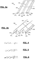
- FIGURES 3a and 3b are schematic representations of a third embodiment, in no way limiting, of the flexible cover element according to the invention.
- the flexible and transparent cover element 300 is shown in the FIGURE 3a flat, and on the FIGURE 3b in its configuration of attachment to a frame (not shown in the FIGURE 1b ) two juxtaposed culture shelters, identical or different, each having a ridge line, namely 302 1 and 302 2 .
- the covering element 300 comprises on a longitudinal edge 304 a series of two fixing openings 304 1 and 304 2 and on the opposite longitudinal edge 306 a series of three fixing openings 306 1 -306 3 .
- the fixing openings 304 1 and 304 2 make it possible to make an adjustment of the tension applied to the cover element 300 on the edge side 304 and the fixing openings 306 1 -306 3 make it possible to make an adjustment of the tension applied to the covering element 300 on the edge side 306.
- the covering element 300 comprises, at an intermediate zone 308, lying between the longitudinal edges 304 and 306, a series of three fixing openings, 308 1 -308 3 offset from one another in a direction perpendicular to the edges 304 and 306, so that the fixing opening 308 1 is closer to the edge 304, the fixing opening 308 3 is located near the edge 306 and the fixing opening 308 2 is between the fixing openings 308 1 and 308 3 .
- the covering element is used to cover the framework of two juxtaposed culture shelters, identical or similar.
- the fixing openings 308 1 -308 3 of the zone 308 are located between the juxtaposed shelters. These fixing openings 308 1 -308 3 make it possible to fix a part of the cover element 300 on one of the juxtaposed shelters and the remaining part of the cover element 300 on the other of the juxtaposed shelters.
- the fixing openings 308 1 -308 3 make it possible to adjust the tension applied to each of the parts of the cover element 300 independently of the other part.
- each culture shelter can benefit from a cover element whose tension is different.
- cover element 300 may comprise several intermediate zones each comprising one or more fixing openings.
- the covering element is in the form of a plastic sheet, for example transparent, made for example of polyethylene, for example of thickness between 80 ⁇ m and 300 ⁇ m, of width between 6.5 m and 10m, length between 15 and 120m.
- each of the fixing openings can be different.
- the width of each of the fixing openings is identical, for example between 2cm and 6cm, in particular 4cm.
- the spacing between two juxtaposed openings of the same series, considered in pairs, may be different.
- the spacing between two juxtaposed openings of the same series, considered two to two can be constant or identical, for example between 2cm and 6cm, in particular 4cm.
- each fixing opening shown in the FIGURES is in a continuous form, extending substantially over the entire length of the longitudinal edge of the covering element.
- at least one, in particular each, fixing opening may be discontinuous.
- a discontinuous attachment opening may be formed by one or more rings aligned and spaced apart.
- the FIGURE 4 is a schematic representation of a first embodiment of a fixing opening.
- the fixing openings shown on the FIGURE 4 are obtained by folding, inward or outward, the cover member on itself at the longitudinal edge of the cover member.
- the folded part is then bonded to the rest of the covering element, along a longitudinal, continuous or discontinuous bonding line. Bonding is preferably done by heating the cover element and compressing the folded part over the rest of the cover element.
- the folded part can have a width chosen by the user, for example of the order of 1 meter. More generally, the folded part may have a free end whose position on the structure can be modified by the user.
- the FIGURE 5 is a schematic representation of a second embodiment of a fixing opening.
- the cover element is made by two layers connected to each other continuously.
- the fixing openings are obtained by gluing, along a line of longitudinal bonding, continuous or discontinuous, of the two layers together. Bonding is preferably done by heating and compressing the two layers together.
- the FIGURE 6 is a schematic representation of a third embodiment of a fixing opening.
- the cover element is produced by two layers independent of each other.
- the fixing openings are obtained by bonding, along a longitudinal, continuous or discontinuous bonding line, the two layers together. Bonding is preferably done by heating and compressing the two layers together.
- FIGURE 7 is a partial schematic representation of an exemplary embodiment of a culture shelter according to the invention.
- the 700 culture shelter shown on the FIGURE 7 is a multi-chapel cultivation shelter and has a frame 702.
- the frame 702 comprises on each longitudinal side of the shelter 700, a gutter 704. On the FIGURE 7 only a channel 704 is shown.
- the frame 702 also comprises a plurality of trusses 706 arranged parallel to each other and aligned in the longitudinal direction of the shelter, materialized by the arrow 708.
- the cultivation shelter 700 comprises a flexible and transparent covering element which can be any of the covering elements 100, 200 or 300 previously described.
- the culture shelter 700 is shown with the cover element 200 of the FIGURE 2 .
- the covering element 200 is fixed to the frame 702 by means of elongated fixing elements 710, identical to each other and which can be assembled together at their adjacent ends, by screwing a elongated fixing element 700 into the fastening element adjacent longiform.
- elongated fixing elements 710 identical to each other and which can be assembled together at their adjacent ends, by screwing a elongated fixing element 700 into the fastening element adjacent longiform.
- the longiform fixing elements 710 are shown unassembled for more details of representation.
- the gutter has hooks or fixing lugs 712 integral with said gutter 712.
- Each fixing lug 712 is slightly bent downwards so as to maintain the elongated fixing element 710 once the latter has been positioned under said fixing lug 712.
- each fixing lug 712 has a sharp end in order to make a hole passing through the covering element 200.
- the fixing of the cover element on the frame 702 is carried out as follows.
- the longiform fixing elements 710 are passed through the fixing opening 206 2 of the edge 206 of the covering element 200. Once passed through the fixing opening 206 3, the longiform fixing elements are screwed together. Then, pressure is applied, for example by an operator using his foot, on each fastening element 710 to pass said elongated fastening element 210 under the fastening tabs 712. In doing so, the fastening tab 712 is forced to pierce through and pass through the cover member 200. Once positioned under the fixing tab 712, the elongated fixing element 710 is held firmly under said fixing tab 712 under the effect of the tension of the covering element 200. This operation is carried out for each tab of fastener 712 and each elongated fastening element 710 along each of the sides of the culture shelter 700.
- FIGURE 8 is a schematic representation of a fourth embodiment, in no way limiting, of the flexible cover element according to the invention.
- the flexible and transparent cover element 800 is shown in the FIGURE 8 includes all the features of the cover element 100 of the FIGURE 1 .
- the cover element 800 comprises at one of its transverse edges, namely the transverse edge 802, perpendicular to its longitudinal edges 104 and 106, a transverse fixing opening 802 1 perpendicular to the longitudinal edges 104 and 106 and to the longitudinal fixing openings 104 1 , 106 1 and 106 2 , and designed to accommodate a elongated fixing element (not shown), such as a tube or a bar, for example made of metal .
- the covering element 800 comprises on the opposite transverse edge, namely the edge 804, a series of two transverse fixing openings, namely the transverse fixing openings 804 1 and 804 2 , perpendicular to the longitudinal edges 104 and 106 and to the longitudinal fixing openings 104 1 , 106 1 and 106 2 .
- These transverse fixing openings 804 1 and 804 2 are offset with respect to each other in a direction perpendicular to the transverse edge 804, so that the transverse fixing opening 804 1 is closer to the transverse edge 804 compared at the fixing opening 804 2 .
- Each of the transverse fixing openings 804 1 and 804 2 is designed to receive a elongated fixing element (not shown).
- the numbers of transverse fixing openings can be different.
Description
La présente invention concerne un élément de couverture souple, telle qu'une bâche, pour abri de culture, de type serre. Elle concerne également un abri de culture muni d'au moins un tel élément de couverture souple.The present invention relates to a flexible covering element, such as a tarpaulin, for a culture shelter, of the greenhouse type. It also relates to a cultivation shelter provided with at least one such flexible covering element.
Le domaine de l'invention est le domaine des abris de culture, notamment le domaine des couvertures souples pour abris de culture.The field of the invention is the field of culture shelters, in particular the field of flexible covers for culture shelters.
Les abris de culture, tels que des serres, sont généralement constitués par une ossature sur laquelle est aménagé un élément de couverture souple, généralement réalisée en plastique.Cultivation shelters, such as greenhouses, generally consist of a frame on which is arranged a flexible cover element, generally made of plastic.
La qualité de fixation de l'élément de couverture souple, également appelé bâche, sur l'ossature présente une importance capitale sur la longévité de l'abri de culture. En effet, lorsque l'élément de couverture souple n'est pas suffisamment tendu, il devient vulnérable en cas de vents forts, ce qui présente des risques de dégâts pour l'abri de culture mais aussi pour les cultures, le personnel pouvant potentiellement se trouver dans ou au voisinage de l'abri de culture et pour l'environnement de l'abri de culture.The quality of fixing of the flexible covering element, also called tarpaulin, on the framework is of capital importance on the longevity of the cultivation shelter. In fact, when the flexible cover element is not sufficiently stretched, it becomes vulnerable in the event of strong winds, which poses risks of damage for the crop shelter but also for the crops, the personnel potentially being able to find in or near the culture shelter and for the environment of the culture shelter.
Une première solution de fixation consiste à pincer l'élément de couverture souple dans un profilé, fixé sur l'ossature de l'abri de culture à l'aide d'une clavette venant se loger dans ledit profilé. Cette solution n'est pas ergonomique et sa mise en œuvre est complexe et chronophage. De plus, elle ne permet pas de tendre suffisamment l'élément de couverture souple entre les deux côtés longitudinaux de l'abri de culture. De plus, le pinçage de l'élément de couverture souple abime ledit élément de couverture souple provoquant sa déchirure dans le temps.A first fixing solution consists in pinching the flexible cover element in a profile, fixed to the framework of the culture shelter using a key which is received in said profile. This solution is not ergonomic and its implementation is complex and time-consuming. In addition, it does not sufficiently stretch the flexible cover element between the two longitudinal sides of the culture shelter. In addition, pinching the flexible cover element damages said flexible cover element causing it to tear over time.
Une autre solution consiste à prévoir un ourlet au niveau de chacune des bordures longitudinales de l'élément de couverture souple. Un élément de fixation longiforme, telle qu'une barre métallique, est introduit dans ledit ourlet, puis coincée sous des pattes de fixation solidaires de l'ossature et faisant saillie de ladite ossature le long de deux côtés longitudinaux de l'abri de culture. Cette solution présente de nombreux avantages par rapport à la première solution. Cependant, la fixation proposée par cette solution est peu flexible et non personnalisable. Elle ne permet pas d'ajuster la tension de l'élément de couverture souple entre les deux côtés longitudinaux de l'abri de culture. Un exemple d'une telle solution peut être trouvé dans
Un but de la présente invention est de remédier à ces inconvénients. Un autre but de l'invention est de proposer un élément de couverture souple pour abri de culture proposant une plus grande flexibilité de fixation sur une ossature d'abri de culture.An object of the present invention is to remedy these drawbacks. Another object of the invention is to provide a flexible cover element for a culture shelter offering greater flexibility of attachment to a culture shelter framework.
Encore un autre but de l'invention est de proposer un élément de couverture souple pour abri de culture permettant une fixation personnalisable sur une ossature d'abri de culture.Yet another object of the invention is to provide a flexible cover element for a culture shelter allowing customizable attachment to a culture shelter framework.
Enfin, un autre but de l'invention est de proposer un élément de couverture souple pour abri de culture permettant d'ajuster la tension dudit élément de couverture souple entre les deux côtés longitudinaux de l'abri de culture.Finally, another object of the invention is to propose a flexible cover element for a culture shelter making it possible to adjust the tension of said flexible cover element between the two longitudinal sides of the culture shelter.
L'invention permet d'atteindre au moins l'un de ces buts par un élément de couverture souple, pour abri de culture, de type serre, prévu pour être fixé sur une ossature dudit abri de culture du côté d'au moins un de ses bords longitudinaux, caractérisé en ce qu'il comprend du côté d'au moins un desdits bords longitudinaux, une série d'au moins deux ouvertures, dites de fixation, en particulier longitudinales, décalées dans une direction perpendiculaire audit bord longitudinal, et prévues chacune pour recevoir sélectivement un élément de fixation longiforme de sorte ajuster la tension dudit élément de couverture en fonction de l'ouverture de fixation utilisée.The invention makes it possible to achieve at least one of these aims by a flexible cover element, for a culture shelter, of the greenhouse type, designed to be fixed to a framework of said culture shelter on the side of at least one of its longitudinal edges, characterized in that it comprises, on the side of at least one of said longitudinal edges, a series of at least two openings, called fixing, in particular longitudinal, openings offset in a direction perpendicular to said longitudinal edge, and provided each for selectively receiving a elongate fixing element so as to adjust the tension of said covering element according to the fixing opening used.
Ainsi, l'invention propose un élément de couverture souple, au moins en partie transparente, comprenant au moins du côté d'un de ses bords longitudinaux une série d'au moins deux ouvertures de fixation distribuées dans le sens de la largeur de l'élément de couverture. Chacune de ces ouvertures est prévue pour accueillir un élément de fixation longiforme, en forme d'un tube ou d'une barre, permettant de fixer l'élément de couverture à l'ossature de l'abri de culture. Par conséquent, en fonction de l'ouverture de fixation utilisée, il est possible de modifier et d'ajuster la tension de l'élément de couverture lorsqu'il est disposé sur l'ossature de l'abri de culture. De ce fait, l'élément de couverture permet de réaliser d'une part, une fixation personnalisable de l'élément de couverture sur l'abri de culture, et d'autre part, un ajustement de la tension dudit élément de couverture souple entre les deux côtés longitudinaux de l'abri de culture.Thus, the invention provides a flexible covering element, at least partially transparent, comprising at least on the side of one of its longitudinal edges a series of at least two fixing openings distributed in the width direction of the cover element. Each of these openings is designed to accommodate a elongated fixing element, in the form of a tube or a bar, making it possible to fix the covering element to the framework of the culture shelter. Therefore, depending on the fixing opening used, it is possible to modify and adjust the tension of the roofing element when it is placed on the framework of the growing shelter. Therefore, the cover element makes it possible on the one hand, a customizable fixing of the cover element on the cultivation shelter, and on the other hand, an adjustment of the tension of said flexible cover element between the two longitudinal sides of the growing shelter.
De plus, lorsque la tension de l'élément de couverture se modifie dans le temps du fait d'une modification de température ou sous l'effet du vieillissement de l'élément de couverture, il est possible de réaliser un nouvel ajustement de cette tension, à la hausse comme à la baisse, en changeant l'ouverture de fixation. Par conséquent, l'élément de couverture selon l'invention permet une plus grande flexibilité de fixation sur une ossature d'abri de culture.In addition, when the tension of the cover element changes over time due to a change in temperature or under the effect of the aging of the cover element, it is possible to make a new adjustment of this tension. , upwards or downwards, by changing the fixing opening. Consequently, the cover element according to the invention allows greater flexibility of attachment to a culture shelter framework.
Selon l'invention, l'expression « du côté d'un bord » de l'élément de couverture désigne en emplacement se trouvant au niveau dudit bord, ou un emplacement se trouvant entre ledit bord et le centre de l'élément de couverture. Ainsi, selon l'invention, lesdites au moins deux ouvertures de fixation longitudinales peuvent être disposées au niveau d'au moins un des bords longitudinaux de l'élément de couverture, ou au niveau d'un emplacement se trouvant entre son centre (par rapport à ses bords longitudinaux) et un bord longitudinal.According to the invention, the expression “on the side of an edge” of the covering element designates a location located at said edge, or a location located between said edge and the center of the covering element. Thus, according to the invention, said at least two longitudinal fixing openings can be arranged at at least one of the longitudinal edges of the cover element, or at a location located between its center (relative at its longitudinal edges) and a longitudinal edge.
L'élément de couverture peut en particulier être transparent au moins en partie. Alternativement, l'élément de couverture peut ne pas être transparent et être opaque.The cover element may in particular be transparent at least in part. Alternatively, the cover element may not be transparent and be opaque.
Par ailleurs, l'élément de couverture peut être réversible.Furthermore, the cover element can be reversible.
Préférentiellement, mais de manière nullement limitative, au moins une ouverture de fixation longitudinale peut se prolonger, de manière continue ou discontinue, sensiblement sur toute la longueur de l'élément de couverture.Preferably, but in no way limiting, at least one longitudinal fixing opening can extend, continuously or discontinuously, substantially over the entire length of the covering element.
Alternativement, au moins une ouverture de fixation longitudinale peut être formée par plusieurs anneaux alignés entre eux, sensiblement sur toute la longueur de l'élément de couverture.Alternatively, at least one longitudinal fixing opening can be formed by several rings aligned with each other, substantially over the entire length of the covering element.
Généralement, mais de manière nullement limitative, l'élément de fixation peut être prévu pour être fixé sur l'ossature de l'abri de culture du côté de deux bords longitudinaux opposés.Generally, but in no way limiting, the fixing element can be provided to be fixed on the framework of the culture shelter on the side of two opposite longitudinal edges.
Suivant un premier mode de réalisation, l'élément de fixation peut comprendre :
- du côté de l'un des bords longitudinaux opposés, une série d'au moins deux ouvertures de fixation, en particulier longitudinales, décalées dans une direction perpendiculaire audit bord longitudinal ; et
- du côté de l'autre desdits bords, une unique ouverture longitudinale de fixation ;
- on the side of one of the opposite longitudinal edges, a series of at least two fixing openings, in particular longitudinal, offset in a direction perpendicular to said longitudinal edge; and
- on the side of the other of said edges, a single longitudinal fixing opening;
Ce mode de réalisation ne permet de réaliser un ajustement ou une modification de la tension de l'élément de couverture (lorsqu'il est fixé à l'ossature de l'abri de culture) uniquement du côté d'un des bords longitudinaux opposés. Ce mode de réalisation présente l'avantage d'un coût de fabrication faible.This embodiment only makes it possible to make an adjustment or a modification of the tension of the cover element (when it is fixed to the framework of the culture shelter) only on the side of one of the opposite longitudinal edges. This embodiment has the advantage of a low manufacturing cost.
Selon un deuxième exemple de réalisation, l'élément de couverture selon l'invention peut comprendre du côté de chacun des bords longitudinaux opposés, une série d'au moins deux ouvertures longitudinales de fixation, décalées dans une direction perpendiculaire audit bord longitudinal, et prévues chacune pour recevoir un élément de fixation longiforme.According to a second exemplary embodiment, the covering element according to the invention may comprise, on the side of each of the opposite longitudinal edges, a series of at least two longitudinal fixing openings, offset in a direction perpendicular to said longitudinal edge, and provided each to receive a elongated fixing element.
Ce mode de réalisation permet de réaliser un ajustement ou une modification de la tension de l'élément de couverture (lorsqu'il est fixé à l'ossature de l'abri de culture) sur chaque côté longitudinal de fixation de l'élément de couverture mobile sur l'abri de culture. Par conséquent, ce mode de réalisation permet une plus grande flexibilité lors de l'ajustement de la tension de l'élément de couverture sur l'abri de fixation que ce soit en termes de quantité d'ajustement.This embodiment makes it possible to make an adjustment or a modification of the tension of the cover element (when it is fixed to the framework of the cultivation shelter) on each longitudinal fixing side of the cover element mobile on the culture shelter. Consequently, this embodiment allows greater flexibility when adjusting the tension of the cover element on the fixing shelter, whether in terms of the amount of adjustment.
De plus, ce mode de réalisation permet un ajustement plus ergonomique et plus rapide pour l'opérateur. En effet, lorsque deux abris de culture sont juxtaposés suivant une direction longitudinale, ce qui est généralement le cas, un opérateur se plaçant entre les deux abris peut réaliser un ajustement de la tension pour les deux abris.In addition, this embodiment allows a more ergonomic and faster adjustment for the operator. In fact, when two cultivation shelters are juxtaposed in a longitudinal direction, which is generally the case, an operator standing between the two shelters can adjust the tension for the two shelters.
En outre, quel que soit le mode de réalisation, l'élément de couverture peut en outre comprendre, au niveau d'au moins une zone, dite intermédiaire, se trouvant entre les bords longitudinaux dudit élément de couverture, au moins une ouverture de fixation ou une série d'au moins deux ouvertures de fixation, en particulier longitudinale(s).In addition, whatever the embodiment, the cover element may further comprise, at at least one zone, called an intermediate, lying between the longitudinal edges of said cover element, at least one fixing opening. or a series of at least two fixing openings, in particular longitudinal (s).
Une telle ouverture de fixation permet en outre d'apporter la possibilité de fixer l'élément de couverture, et éventuellement d'ajuster la tension de l'élément de couverture, au niveau d'une ou plusieurs zones intermédiaires autres que les bords longitudinaux de l'élément de couverture souple.Such a fixing opening also makes it possible to provide the possibility of fixing the cover element, and possibly of adjusting the tension of the cover element, at one or more intermediate zones other than the longitudinal edges of the flexible cover element.
Ce mode de réalisation permet en outre d'utiliser un même élément de couverture pour couvrir deux ou plusieurs abris de culture juxtaposés, tout en permettant d'ajuster de manière individuelle la tension de la partie de l'élément de couverture associée à chaque abri de culture.This embodiment also makes it possible to use the same cover element to cover two or more juxtaposed culture shelters, while allowing the tension of the part of the cover element associated with each shelter to be adjusted individually. culture.
L'élément de couverture souple peut en outre comprendre au moins une ouverture de fixation, en particulier une série d'au moins deux ouvertures de fixation, dite transversale(s), en particulier disposés dans le sens de la largeur dudit élément de couverture souple, et en particulier suivant une direction perpendiculaire aux bords longitudinaux dudit élément de couverture.The flexible cover element may further comprise at least one fixing opening, in particular a series of at least two fixing openings, called transverse (s), in particular arranged across the width of said flexible cover element. , and in particular in a direction perpendicular to the longitudinal edges of said covering element.
Lorsque l'élément de couverture souple comprend une série d'au moins deux ouvertures de fixation transversales, lesdites ouvertures de fixation transversales peuvent être décalées les unes par rapport aux autres suivant une direction parallèle à un bord longitudinal dudit élément de couverture.When the flexible covering element comprises a series of at least two transverse fixing openings, said transverse fixing openings can be offset with respect to each other in a direction parallel to a longitudinal edge of said covering element.
Plus particulièrement, l'élément de couverture souple peut comprendre une ouverture de fixation transversale ou une série d'au moins deux ouvertures transversales, disposée au niveau d'au moins un, en particulier de chacun, de ses bords perpendiculaires à ses bords longitudinales.More particularly, the flexible cover element may comprise a transverse fixing opening or a series of at least two transverse openings, arranged at at least one, in particular of each, of its edges perpendicular to its longitudinal edges.
Préférentiellement, mais de manière nullement limitative, au moins une ouverture de fixation transversale peut se prolonger, de manière continue ou discontinue, sensiblement sur toute la largeur de l'élément de couverture.Preferably, but in no way limiting, at least one transverse fixing opening can extend, continuously or discontinuously, substantially over the entire width of the covering element.
Alternativement, au moins une ouverture de fixation transversale peut être formée par plusieurs anneaux alignés entre eux, sensiblement sur toute la largeur de l'élément de couverture.Alternatively, at least one transverse fixing opening can be formed by several rings aligned with each other, substantially over the entire width of the covering element.
Avantageusement, au moins une, en particulier chaque, ouverture de fixation peut être formée par repliement de l'élément de couverture sur lui-même au niveau d'un bord, et collage de la partie repliée sur le reste dudit élément de couverture suivant une ligne de collage, continue ou discontinue. Lorsqu'il s'agit d'une ouverture de fixation longitudinale, la ligne de collage est longitudinale et lorsqu'il s'agit d'une ouverture de fixation transversale, la ligne de collage est transversale, en particulier perpendiculaire aux bords latéraux.Advantageously, at least one, in particular each, fixing opening can be formed by folding the cover element back on itself at an edge, and gluing the folded part over the rest of said cover element according to a bonding line, continuous or discontinuous. When it is a longitudinal fixing opening, the bonding line is longitudinal and when it is a transverse fixing opening, the bonding line is transverse, in particular perpendicular to the lateral edges.
Ainsi, il est possible de réaliser une ouverture de fixation unique, ou une série de plusieurs ouvertures de fixation.Thus, it is possible to produce a single fixing opening, or a series of several fixing openings.
Par ailleurs, lorsque l'élément de couverture est réalisé, au moins en partie, par assemblage/association d'au moins deux feuilles/couches de couverture souples, au moins une, en particulier, chaque ouverture de fixation peut être réalisée par collage entre-elles de deux desdites feuilles/couches suivant une ligne de collage, continue ou discontinue.Furthermore, when the covering element is produced, at least in part, by assembly / association of at least two flexible cover sheets / layers, at least one, in particular, each fixing opening can be produced by bonding between they of two of said sheets / layers along a bonding line, continuous or discontinuous.
Lorsqu'il s'agit d'une ouverture de fixation longitudinale, la ligne de collage est longitudinale et lorsqu'il s'agit d'une ouverture de fixation transversale, la ligne de collage est transversale, en particulier perpendiculaire aux bords latéraux.When it is a longitudinal fixing opening, the bonding line is longitudinal and when it is a transverse fixing opening, the bonding line is transverse, in particular perpendicular to the lateral edges.
En outre, au moins une, en particulier chaque, ouverture de fixation, peut être formée par collage audit élément de couverture, par exemple sur une surface supérieure de l'élément de couverture, d'un anneau, ou d'une série d'anneaux alignés, réalisé(s) indépendamment dudit élément de couverture.Furthermore, at least one, in particular each, fixing opening, can be formed by bonding to said covering element, for example on an upper surface of the covering element, with a ring, or a series of aligned rings, produced independently of said covering element.
Le ou les anneaux sont disposés suivant une ligne longitudinale lorsqu'il s'agit d'une ouverture de fixation longitudinale, suivant une ligne traversable, en particulier perpendiculaire aux bords latéraux, lorsqu'il s'agit d'une ouverture de fixation transversale.The ring or rings are arranged along a longitudinal line when it is a longitudinal fixing opening, along a traversable line, in particular perpendicular to the lateral edges, when it is a transverse fixing opening.
Dans ce cas, le ou les anneaux peuvent être réalisés avec la même matière que, ou avec une matière différente de, celle utilisée pour fabriquer l'élément de couvertureIn this case, the ring (s) can be made of the same material as, or with a material different from that used to manufacture the covering element
Quel que soit le mode de réalisation, le collage peut être réalisé par apport d'une substance collante ou adhésive, externe à l'élément de couverture.Whatever the embodiment, bonding can be carried out by adding a sticky or adhesive substance, external to the covering element.
Préférentiellement, le collage peut être réalisé par chauffage et compression :
- de l'élément de couverture lui-même ;
- entre-elles, d'au moins couches/feuilles formant ledit élément de couverture ; ou
- de l'élément de couverture avec le ou les anneaux indépendants.
- of the cover element itself;
- between them, at least layers / sheets forming said covering element; or
- of the cover element with the independent ring (s).
Ce mode de réalisation est plus simple à mettre en œuvre comparé à l'utilisation d'une substance collante ou adhésive.This embodiment is simpler to implement compared to the use of a sticky or adhesive substance.
Autrement dit, le collage peut être réalisé par thermocollage ou soudure.In other words, bonding can be carried out by heat bonding or welding.
Pour au moins une série, longitudinale ou transversale, comprenant plusieurs ouvertures de fixation :
- au moins deux ouvertures de fixation de ladite série peuvent présenter une taille identique ou différente ; et/ou
- les ouvertures de fixation de ladite série peuvent être décalées les unes des autres suivant un pas d'écartement constant ou variable.
- at least two fixing openings of said series may have the same or different size; and or
- the fixing openings of said series can be offset from each other at a constant or variable spacing pitch.
De plus, lorsque l'élément de couverture comprend plusieurs séries comprenant chacune au moins deux ouvertures de fixation :
- au moins une ouverture de fixation d'une desdites séries, se trouvant par exemple du côté d'un des bords de l'élément de couverture, peut présenter une taille identique à, ou différente de, la taille d'au moins une ouverture de fixation d'une autre série, se trouvant par exemple du côté d'un autre bord de l'élément de couverture ; et/ou
- au moins deux ouvertures de fixation d'une desdites séries, se trouvant par exemple du côté d'un des bords de l'élément de couverture, peuvent présenter entre-elles un pas d'écartement identique au, ou différent du, pas d'écartement entre au moins deux ouvertures de fixation d'une autre série, se trouvant par exemple du côté d'un autre bord de l'élément de couverture.
- at least one fixing opening of one of said series, being for example on the side of one of the edges of the covering element, may have a size identical to, or different from, the size of at least one opening of fixing another series, being for example on the side of another edge of the cover element; and or
- at least two fixing openings of one of said series, being for example on the side of one of the edges of the cover element, may have between them a spacing pitch identical to, or different from, the pitch of spacing between at least two fixing openings of another series, being for example on the side of another edge of the cover element.
Suivant un exemple de réalisation préféré, mais nullement limitatif :
- au moins une ouverture de fixation présente une largeur comprise entre 2 et 6cm, en particulier une largeur égale à 4cm ; et/ou
- au moins deux ouvertures de fixation d'une série présentent entre-elles un pas d'écartement compris entre 2 et 6cm, en particulier un pas d'écartement de 4cm.
- at least one fixing opening has a width of between 2 and 6cm, in particular a width of 4cm; and or
- at least two fixing openings in a series have between them a spacing pitch of between 2 and 6 cm, in particular a spacing pitch of 4 cm.
Toujours suivant un exemple de réalisation préféré, mais nullement limitatif, l'élément de couverture souple peut comprendre un nombre d'ouvertures de fixation compris entre 2 et 4, en particulier entre 2 et 3, pour chaque série se trouvant du côté de chacun des bords longitudinaux opposés.Still according to a preferred embodiment, but in no way limiting, the flexible cover element may include a number of fixing openings between 2 and 4, in particular between 2 and 3, for each series located on the side of each of the opposite longitudinal edges.
Selon un autre aspect de l'invention il est proposé un kit de couverture pour abri de culture, de type serre, comprenant :
- un élément de couverture selon l'invention, et
- au moins un, en particulier plusieurs, élément(s) de fixation longiforme(s), prévu(s) pour fixer ledit élément de couverture sur une ossature dudit abri de culture.
- a cover element according to the invention, and
- at least one, in particular several, elongated fixing element (s), provided (s) for fixing said covering element on a framework of said cultivation shelter.
Bien entendu les éléments de fixation longiforme peuvent être prévus pour être utilisé du côté de chaque bord longitudinal de l'élément de couverture.Of course the elongate fixing elements can be provided to be used on the side of each longitudinal edge of the covering element.
Selon l'invention, chaque élément de fixation longiforme peut présenter une longueur sensiblement égale à la longueur de l'abri de culture à couvrir.According to the invention, each elongated fixing element may have a length substantially equal to the length of the culture shelter to be covered.
Alternativement, chaque élément de fixation longiforme peut présenter une longueur inférieure ou égale à la moitié de la longueur de l'abri de culture à couvrir. Il est alors nécessaire d'utiliser au moins deux éléments de fixation longiformes pour fixer l'élément de couverture à l'ossature de l'abri de culture. Dans ce cas, au moins un, en particulier chaque, élément de fixation longiforme peut comporter au niveau d'au moins une, en particulier de chacune, de ses extrémités un moyen d'assemblage, amovible ou démontable, dudit élément de fixation longiforme avec un autre élément de fixation longiforme, en particulier qui lui est identique.Alternatively, each elongated fixing element may have a length less than or equal to half the length of the culture shelter to be covered. It is then necessary to use at least two elongated fixing elements to fix the covering element to the framework of the culture shelter. In this case, at least one, in particular each, elongated fixing element may comprise, at at least one, in particular of each of its ends, a means of assembly, removable or removable, of said elongated fixing element with another elongated fixing element, in particular identical to it.
Avantageusement, un tel moyen d'assemblage de deux éléments de fixation longiformes entre eux peut réaliser un assemblage par vissage, par clipsage, par serrage, etc.Advantageously, such a means of assembling two elongated fastening elements together can produce an assembly by screwing, by clipping, by clamping, etc.
Selon encore un autre aspect de l'invention, il est proposé un abri de culture, de type serre, comprenant :
- une ossature, en particulier rigide, et
- au moins un kit de couverture selon l'invention, ou au moins un élément de couverture souple selon l'invention.
- a framework, in particular rigid, and
- at least one cover kit according to the invention, or at least one flexible cover element according to the invention.
Suivant un mode de réalisation préféré, mais nullement limitatif, l'ossature de l'abri de culture selon l'invention peut comprendre, du côté d'au moins une, en particulier de chacune, des faces latérales longitudinales dudit abri, plusieurs pattes de fixation, en particulier formant saillie de ladite ossature, alignées longitudinalement les unes avec les autres, sensiblement sur toute la longueur de ladite face latérale, et prévues pour maintenir le ou les élément(s) de fixation longiforme(s) préalablement passés dans une ouverture de fixation.According to a preferred, but in no way limiting, embodiment, the framework of the culture shelter according to the invention may comprise, on the side of at least one, in particular of each, of the longitudinal lateral faces of said shelter, several legs of fixing, in particular protruding from said frame, aligned longitudinally with one another, substantially over the entire length of said lateral face, and designed to hold the long-shaped fixing element (s) previously passed through an opening of fixation.
En particulier les pattes de fixation peuvent être prévues et positionnées de sorte que les éléments de fixation longiformes viennent se loger en dessous des pattes de fixation après application d'un effort sur lesdits éléments de fixation longiformes, ce qui a pour effet de tendre l'élément de couverture.In particular, the fixing lugs can be provided and positioned so that the elongated fixing elements are housed below the fixing lugs after application of a force on said elongated fixing elements, which has the effect of tightening the cover element.
L'élément de couverture peut être muni de trous traversants laissant traverser les pattes de fixation lors du positionnement des éléments de fixation longiformes sous les pattes de fixation. Ces trous traversants peuvent être réalisés lors de la fabrication de l'élément de couverture ou lors de la pose de l'élément de couverture sur l'abri.The cover element can be provided with through holes allowing the fixing lugs to pass through when positioning the elongated fixing elements under the fixing lugs. These through holes can be made during the manufacture of the cover element or during the installation of the cover element on the shelter.
Alternativement, au moins une, en particulier chaque, patte de fixation peut présenter une extrémité libre pointue ou coupante de sorte qu'elle réalise le trou traversant, par perforation de l'élément de couverture, au moment où l'élément de fixation longiforme est poussé sous ladite patte de fixation par application d'un effort sur ledit élément de fixation longiforme, par un opérateur par exemple.Alternatively, at least one, in particular each, fixing lug may have a pointed or cutting free end so that it makes the through hole, by perforation of the covering element, at the moment when the elongated fixing element is pushed under said fixing lug by application of a force on said elongated fixing element, by an operator for example.
L'abri de culture selon l'invention peut être un abri de culture multi-chapelle, un tunnel, un bi-tunnel, un tunnel de jardin, un tunnel de potager, etc.The cultivation shelter according to the invention can be a multi-chapel cultivation shelter, a tunnel, a bi-tunnel, a garden tunnel, a vegetable garden tunnel, etc.
D'autres avantages et caractéristiques apparaîtront à l'examen de la description détaillée d'un mode de réalisation nullement limitatif, et des dessins annexés sur lesquels :
- les
FIGURES 1a et 1b sont des représentations schématiques d'un premier exemple de réalisation d'un élément de couverture selon l'invention ; - les
FIGURES 2a et 2b sont des représentations schématiques d'un deuxième exemple de réalisation d'un élément de couverture selon l'invention ; - les
FIGURES 3a et 3b sont des représentations schématiques d'un troisième exemple de réalisation d'un élément de couverture selon l'invention ; - la
FIGURE 4 est une représentation schématique d'un premier exemple de réalisation d'une ouverture de fixation ; - la
FIGURE 5 est une représentation schématique d'un deuxième exemple de réalisation d'une ouverture de fixation ; - la
FIGURE 6 est une représentation schématique d'un troisième exemple de réalisation d'une ouverture de fixation ; - la
FIGURE 7 est une représentation d'un exemple d'abri de culture selon l'invention ; et - la
FIGURE 8 est une représentation schématique d'un quatrième exemple de réalisation d'un élément de couverture selon l'invention.
- the
FIGURES 1a and 1b are schematic representations of a first embodiment of a cover element according to the invention; - the
FIGURES 2a and 2b are schematic representations of a second embodiment of a cover element according to the invention; - the
FIGURES 3a and 3b are schematic representations of a third embodiment of a cover element according to the invention; - the
FIGURE 4 is a schematic representation of a first embodiment of a fixing opening; - the
FIGURE 5 is a schematic representation of a second embodiment of a fixing opening; - the
FIGURE 6 is a schematic representation of a third embodiment of a fixing opening; - the
FIGURE 7 is a representation of an example of a culture shelter according to the invention; and - the
FIGURE 8 is a schematic representation of a fourth embodiment of a cover element according to the invention.
Il est bien entendu que les modes de réalisation qui seront décrits dans la suite ne sont nullement limitatifs. On pourra notamment imaginer des variantes de l'invention ne comprenant qu'une sélection de caractéristiques décrites par la suite isolées des autres caractéristiques décrites, si cette sélection de caractéristiques est suffisante pour conférer un avantage technique ou pour différencier l'invention par rapport à de l'état de la technique antérieur. Cette sélection comprend au moins une caractéristique de préférence fonctionnelle sans détails structurels, ou avec seulement une partie des détails structurels si cette partie est uniquement suffisante pour conférer un avantage technique ou pour différencier l'invention par rapport à l'état de la technique antérieur.It is understood that the embodiments which will be described below are in no way limiting. It is possible in particular to imagine variants of the invention comprising only a selection of characteristics described hereinafter isolated from the other characteristics described, if this selection of characteristics is sufficient to confer a technical advantage or to differentiate the invention with respect to the state of the prior art. This selection comprises at least one preferably functional characteristic without structural details, or with only a part of the structural details if this part is only sufficient to confer a technical advantage or to differentiate the invention from the state of the prior art.
Sur les figures, les éléments communs à plusieurs figures conservent la même référence.In the figures, the elements common to several figures keep the same reference.
Les
L'élément de couverture souple et transparente 100 est représenté sur la
L'élément de couverture 100 représenté sur les
L'élément de couverture 100 comporte au niveau d'un de ses bords, à savoir le bord 104, une unique ouverture de fixation, à savoir l'ouverture de fixation 1041 prévue pour accueillir un élément de fixation longiforme (non représenté sur les FIGURES la et 1b), tel qu'un tube ou une barre, par exemple réalisé en métal.The
L'élément de couverture 100 comporte sur le bord opposé, à savoir le bord 106, une série de deux ouvertures de fixation, à savoir les ouvertures de fixation 1061 et 1062. Ces ouvertures de fixation 1061 et 1062 sont décalées l'une par rapport à l'autre suivant une direction perpendiculaire au bord 106, de sorte que l'ouverture de fixation 1061 se trouve plus proche du bord 106 comparée à l'ouverture de fixation 1062. Chacune des ouvertures de fixation 1061 et 1062 est prévue pour accueillir un élément de fixation longiforme (non représenté sur les
Lors de la fixation de l'élément de couverture 100 sur un abri de culture, il est possible de modifier ou d'ajuster la tension appliquée à audit élément de couverture 100, entre ses bords 104 et 106, en choisissant l'une ou l'autre des ouvertures de fixation 1061 ou 1062 du bord longitudinal 106. Plus précisément, pour une même ossature d'abri de culture, la tension appliquée à l'élément de couverture entre ses bords 104 et 106 sera plus grande si l'élément de couverture est fixé à l'aide de l'ouverture de fixation 1062. Ainsi, pour une même ossature d'abri de culture, la tension appliquée à l'élément de couverture entre ses bords 104 et 106 sera plus faible si l'élément de couverture est fixé à l'aide de l'ouverture de fixation 1061.When fixing the
Les
L'élément de couverture souple et transparente 200 est représenté sur la
L'élément de couverture 200 représenté sur les
L'élément de couverture 200 comporte au niveau d'un de ses bords, à savoir le bord 204, une série de deux ouvertures de fixation, à savoir les ouvertures de fixation 2041 et 2042. Ces ouvertures de fixation 2041 et 2042 sont décalées l'une par rapport à l'autre suivant une direction perpendiculaire au bord 204, de sorte que l'ouverture de fixation 2041 se trouve plus proche du bord 204 comparée à l'ouverture de fixation 2042. Chacune des ouvertures de fixation 2041 et 2042 du bord 204 est prévue pour accueillir un élément de fixation longiforme (non représenté sur les
L'élément de couverture 200 comporte sur le bord longitudinal opposé, à savoir le bord 206, une série de trois ouvertures de fixation, à savoir les ouvertures de fixation 2061, 2062 et 2063. Chacune des ouvertures de fixation 2061, 2062 et 2063 sont décalées les unes par rapport aux autres suivant une direction perpendiculaire au bord 206, de sorte que l'ouverture de fixation 2061 est la plus proche du bord 206, l'ouverture 2063 est la plus éloignée du bord 206 et l'ouverture 2062 se trouve entre les ouvertures de fixation 2061 et 2063. Chacune des ouvertures de fixation 2061-2063 est prévue pour accueillir un élément de fixation longiforme (non représenté sur les
Avec l'élément de couverture 200, il est possible de modifier ou d'ajuster la tension appliquée à audit élément de couverture 100, entre ses bords 204 et 206, du côté de chacun des bords 204 et 206. Plus l'ouverture de fixation choisie sera proche du bord, moins la tension appliquée à l'élément de couverture entre ses deux bords sera faible, et vice versa. With the
Les
L'élément de couverture souple et transparente 300 est représenté sur la
De manière similaire, ou identique, à l'élément de couverture 200 des
De plus, l'élément de couverture 300 comporte au niveau d'une zone intermédiaire 308, se trouvant entre les bords longitudinaux 304 et 306, une série de trois ouvertures de fixations, 3081-3083 décalées les unes par rapport aux autres dans une direction perpendiculaire aux bords 304 et 306, de sorte que l'ouverture de fixation 3081 se trouve plus proche du bord 304, l'ouverture de fixation 3083 se trouve proche du bord 306 et l'ouverture de fixation 3082 se trouve entre les ouvertures de fixation 3081 et 3083.In addition, the covering
Tel que montré sur la
Bien entendu, l'élément de couverture 300 peut comporter plusieurs zones intermédiaires comprenant chacune une ou plusieurs ouvertures de fixation.Of course, the
Sur tous les exemples décrits, l'élément de couverture se présente sous la forme d'une bâche plastique, par exemple transparente, réalisée par exemple en polyéthylène, par exemple d'épaisseur comprise entre 80µm et 300µm, de largeur comprise entre 6,5m et 10m, de longueur comprise entre 15 et 120m.In all of the examples described, the covering element is in the form of a plastic sheet, for example transparent, made for example of polyethylene, for example of thickness between 80 μm and 300 μm, of width between 6.5 m and 10m, length between 15 and 120m.
La largeur de chacune des ouvertures de fixation peut être différente. Alternativement, la largeur de chacune des ouvertures de fixation est identique, par exemple comprise entre 2cm et 6cm, en particulier de 4cm.The width of each of the fixing openings can be different. Alternatively, the width of each of the fixing openings is identical, for example between 2cm and 6cm, in particular 4cm.
L'écartement entre deux ouvertures juxtaposées d'une même série, considérées deux à deux, peut être différent. Alternativement, l'écartement entre deux ouvertures juxtaposées d'une même série, considérées deux à deux, peut être constante ou identique, par exemple compris entre 2cm et 6cm, en particulier de 4cm.The spacing between two juxtaposed openings of the same series, considered in pairs, may be different. Alternatively, the spacing between two juxtaposed openings of the same series, considered two to two, can be constant or identical, for example between 2cm and 6cm, in particular 4cm.
Bien entendu, le nombre des ouvertures de fixation au niveau de chacun des bords longitudinaux et au niveau de la zone intermédiaire peut être différent de ceux décrits en référence aux FIGURES.Of course, the number of fixing openings at each of the longitudinal edges and at the intermediate zone may be different from those described with reference to the FIGURES.
En outre, chaque ouverture de fixation représentée sur les FIGURES se présente sous une forme continue, s'étendant sensiblement sur toute la longueur du bord longitudinal de l'élément de couverture. Alternativement, au moins une, en particulier chaque, ouverture de fixation peut être discontinue. Par exemple, une ouverture de fixation discontinue peut être formée par un ou plusieurs anneaux alignés et distants entre eux.In addition, each fixing opening shown in the FIGURES is in a continuous form, extending substantially over the entire length of the longitudinal edge of the covering element. Alternatively, at least one, in particular each, fixing opening may be discontinuous. For example, a discontinuous attachment opening may be formed by one or more rings aligned and spaced apart.
La
Les ouvertures de fixation représentées sur la
La partie repliée peut présenter une largeur choisie par l'utilisateur, par exemple de l'ordre de 1mètre. Plus généralement la partie repliée peut comporter une extrémité libre dont la position sur la structure peut être modifiée par l'utilisateur.The folded part can have a width chosen by the user, for example of the order of 1 meter. More generally, the folded part may have a free end whose position on the structure can be modified by the user.
La
Dans l'exemple décrit sur la
La
Dans l'exemple décrit sur la
La
L'abri de culture 700 représenté sur la
L'ossature 702 comporte également une pluralité de fermes 706 disposées parallèles entre elles et alignées suivant la direction longitudinale de l'abri, matérialisée par la flèche 708.The
L'abri de culture 700 selon l'invention comporte un élément de couverture souple et transparente qui peut être l'un quelconque des éléments de couverture 100, 200 ou 300 préalablement décrits. Dans l'exemple représenté, l'abri de culture 700 est représenté avec l'élément de couverture 200 de la
L'élément de couverture 200 est fixé à l'ossature 702 grâce à des éléments de fixation longiforme 710, identiques entre eux et pouvant être assemblés entre eux au niveau de leurs extrémités adjacentes, par vissage d'un élément de fixation longiforme 700 dans l'élément de fixation longiforme adjacent. Sur la
Le chéneau comporte des crochets ou pattes de fixation 712 solidaires dudit chéneau 712. Chaque patte de fixation 712 est légèrement recourbée vers le bas de sorte à maintenir l'élément de fixation longiforme 710 une fois que ce dernier a été positionné sous ladite patte de fixation 712. De plus, chaque patte de fixation 712 présente une extrémité tranchante en vue de réaliser un trou traversant l'élément de couverture 200.The gutter has hooks or fixing
La fixation de l'élément de couverture sur l'ossature 702 est réalisée de la manière suivante. Les éléments de fixation longiformes 710 sont passés dans l'ouverture de fixation 2062 du bord 206 de l'élément de couverture 200. Une fois passés dans l'ouverture de fixation 2063 les éléments de fixation longiforme sont vissés entre eux. Puis, une pression est appliquée, par exemple par un opérateur à l'aide de son pied, sur chaque élément de fixation 710 pour faire passer ledit élément de fixation longiforme 210 sous les pattes de fixation 712. Ce faisant, la patte de fixation 712 est forcée à transpercer l'élément de couverture 200 et à le traverser. Une fois positionné sous la patte de fixation 712, l'élément de fixation longiforme 710 est maintenu fermement sous la dite patte de fixation 712 sous l'effet de la tension de l'élément de couverture 200. Cette opération est réalisée pour chaque patte de fixation 712 et chaque élément de fixation longiforme 710 le long de chacun des côtés de l'abri de culture 700.The fixing of the cover element on the
La
L'élément de couverture souple et transparente 800 est représenté sur la
En plus, l'élément de couverture 800 comprend au niveau d'un de ses bords transversaux, à savoir le bord transversal 802, perpendiculaire à ses bords longitudinaux 104 et 106, une ouverture de fixation transversale 8021 perpendiculaire aux bords longitudinaux 104 et 106 et aux ouvertures de fixation longitudinales 1041, 1061 et 1062, et prévue pour accueillir un élément de fixation longiforme (non représenté), tel qu'un tube ou une barre, par exemple réalisé en métal.In addition, the
L'élément de couverture 800 comporte sur le bord transversal opposé, à savoir le bord 804, une série de deux ouvertures de fixation transversales, à savoir les ouvertures de fixation transversales 8041 et 8042, perpendiculaires aux bords longitudinaux 104 et 106 et aux ouvertures de fixation longitudinales 1041, 1061 et 1062. Ces ouvertures de fixation transversales 8041 et 8042 sont décalées l'une par rapport à l'autre suivant une direction perpendiculaire au bord transversal 804, de sorte que l'ouverture de fixation transversal 8041 se trouve plus proche du bord transversal 804 comparée à l'ouverture de fixation 8042. Chacune des ouvertures de fixation transversales 8041 et 8042 est prévue pour accueillir un élément de fixation longiforme (non représenté).The
Lors de la fixation de l'élément de couverture 800 sur un abri de culture, il est possible de modifier ou d'ajuster la tension appliquée à audit élément de couverture 800, entre ses bords transversaux 802 et 804, en choisissant l'une ou l'autre des ouvertures de fixation transversales 8041 ou 8042. Plus précisément, pour une même ossature d'abri de culture, la tension appliquée à l'élément de couverture entre ses bords transversaux 802 et 804 sera plus grande si l'élément de couverture est fixé à l'aide de l'ouverture de fixation 8042.When fixing the
Alternativement les nombres d'ouvertures de fixation transversales peuvent être différents.Alternatively the numbers of transverse fixing openings can be different.
Plus généralement, l'élément de couverture peut comprendre :
- une série d'au moins deux ouvertures de fixation longitudinales du côté d'un de ses bords longitudinaux,
- et éventuellement au moins une ouverture de fixation longitudinale du côté de l'autre de ses bords longitudinaux,
- et éventuellement au moins une ouverture de fixation transversale du côté d'au moins un, en particulier de chacun, de ses bords transversaux,
- et éventuellement une ou plusieurs ouvertures de fixation longitudinales, respectivement transversales, entre ses bords longitudinaux, respectivement transversaux.
- a series of at least two longitudinal fixing openings on the side of one of its longitudinal edges,
- and possibly at least one longitudinal fixing opening on the side of the other of its longitudinal edges,
- and possibly at least one transverse fixing opening on the side of at least one, in particular each, of its transverse edges,
- and optionally one or more longitudinal, respectively transverse fixing openings between its longitudinal, respectively transverse edges.
Bien entendu, l'invention n'est pas limitée aux exemples détaillés ci-dessus. Of course, the invention is not limited to the examples detailed above.
Claims (14)
- Flexible cover element (100, 200, 300) for a greenhouse-type crop shelter (700), wherein said element is designed to be fixed on a framework (702) of said crop shelter (700) on the side of at least one of its longitudinal edges (104, 106; 204, 206; 304, 306), characterised in that said element comprises on the side of the at least one of said longitudinal edges (106; 204, 206; 304, 306), a series of at least two openings (1061, 1062; 2041, 2042; 2061-2063; 3041, 3042; 3061-3063), termed attachment openings, offset in a perpendicular direction to said longitudinal edge (106; 204, 206; 304, 306), and wherein each attachment opening is designed to selectively receive an elongate attachment element (710), so as to adjust the tension of said cover element according to the attachment opening used.
- Cover element (100) according to claim 1, characterised in that it is designed to be attached to the framework (702) of the crop shelter (700) by the two longitudinally opposite edges (104, 106), wherein said cover element (100) comprises:- on the side of one of the said longitudinally opposite edges (106), a series of at least two attachment openings (1061, 1062), offset in a perpendicular direction to said longitudinal edge (106) so as to adjust the tension of said cover element according to the attachment opening used; and- on the side of the other of the said longitudinally opposite edges (104), a sole attachment opening (1041);each (1041, 1061, 1062) designed to receive an elongate attachment element (710).
- Cover element (200, 300) according to claim 1, characterised in that it is designed to be fixed on the framework (702) of the crop shelter (700) on the side of two longitudinally opposite edges (204, 206; 304, 306), wherein said cover element (200, 300) comprises on the side of each of said longitudinally opposite edges (204, 206; 304, 306), a series of at least two attachment openings (2041, 2042; 2061-2063; 3041, 3042; 3061-3063), offset in a perpendicular direction to said longitudinal edge (204, 206; 304, 306), and wherein each attachment opening is designed to receive an elongate attachment element (710), so as to adjust the tension of said cover element according to the attachment opening used.
- Cover element (300) according to one of the preceding claims, characterised in that it additionally comprises an attachment opening or a series of at least two attachment openings (3081-3083) located in at least one zone (308), termed intermediate zone, between its two longitudinal edges (304, 306).
- Cover element according to one of the preceding claims, characterised in that at least one attachment opening is formed by folding said cover element back on itself at an edge of said cover element, and bonding the folded-back part onto the remainder of said cover element along a continuous or discontinuous bond line.
- Cover element according to one of the preceding claims, characterised in that it is produced, at least partly, by assembling at least two flexible cover sheets, wherein at least one attachment opening is formed by bonding the two said sheets together along a continuous or discontinuous, longitudinal bond line.
- Cover element according to one of the preceding claims, characterised in that at least one attachment opening is formed by bonding to said cover element at least one ring, or a series of aligned rings, produced independently of said cover element.
- Cover element according to one of the preceding claims, characterised in that for at least one series of at least two attachment openings:- at least two attachment openings of said series are of the same or different size; and/or- the attachment openings of said series are spaced apart from one another with a constant or variable spacing.
- Cover element according to one of claims 3 to 8, characterised in that:- at least one attachment opening of a series located on the side of one edge is identical to or different in size from the size of at least one attachment opening of a series located on the side of the other edge; and/or- at least two attachment openings of a series located on the side of one edge are spaced apart from one another with an identical or different spacing to the spacing between the at least two attachment openings of a series located on the side of the other edge.
- Cover element according to one of the preceding claims, characterised in that:- the width of at least one attachment opening is between 2-6 cm; and/or- the spacing between at least two attachment openings of a series is between 2-6 cm.
- Cover element (200, 300) according to one of claims 3 to 10, characterised in that it comprises between 2 and 4 attachment openings for each series located on the side of each of the opposite longitudinal edges (204,206; 304,306).
- Covering kit for a greenhouse-type crop shelter (700), comprising:- a cover element (100, 200, 300) according to one of the preceding claims, and- at least one, in particular a plurality of elongate attachment element(s) (710), designed for attaching said cover element (100, 200, 300) on a framework (702) of said crop shelter (700).
- Greenhouse-type crop shelter (700), comprising:- a framework (702), in particular a rigid framework, and- at least one covering kit according to the preceding claim, or at least one flexible cover element (100, 200, 300) according to one of claims 1 to 11.
- Crop shelter (700) according to the preceding claim, characterised in that the framework (702) comprises on the side of at least one, in particular of each of the longitudinal lateral side faces of said shelter (700), a plurality of attachment fittings (712), aligned longitudinally to one another, substantially along the total length of said lateral side face, and designed to maintain the elongate attachment element(s) (710), passed beforehand into an attachment opening (2062).
Applications Claiming Priority (2)
| Application Number | Priority Date | Filing Date | Title |
|---|---|---|---|
| FR1554996A FR3036921B1 (en) | 2015-06-02 | 2015-06-02 | SOFT COVERING ELEMENT FOR CULTIVATION SHELTER, CULTIVATION SHELTER PROVIDED WITH SUCH A COVERING ELEMENT. |
| PCT/EP2016/062353 WO2016193293A1 (en) | 2015-06-02 | 2016-06-01 | Flexible cover element for a crop shelter, crop shelter provided with such a cover element |
Publications (2)
| Publication Number | Publication Date |
|---|---|
| EP3302028A1 EP3302028A1 (en) | 2018-04-11 |
| EP3302028B1 true EP3302028B1 (en) | 2020-03-25 |
Family
ID=54014997
Family Applications (1)
| Application Number | Title | Priority Date | Filing Date |
|---|---|---|---|
| EP16732453.2A Active EP3302028B1 (en) | 2015-06-02 | 2016-06-01 | Flexible cover element for a crop shelter, crop shelter provided with such a cover element |
Country Status (4)
| Country | Link |
|---|---|
| EP (1) | EP3302028B1 (en) |
| ES (1) | ES2784604T3 (en) |
| FR (1) | FR3036921B1 (en) |
| WO (1) | WO2016193293A1 (en) |
Family Cites Families (4)
| Publication number | Priority date | Publication date | Assignee | Title |
|---|---|---|---|---|
| AU502006B2 (en) * | 1974-09-25 | 1979-07-12 | Bennett, Peter Reginald Dane | Cover for seedlings |
| FR2569523A1 (en) * | 1984-09-06 | 1986-03-07 | Ortiz Antoine | Improved greenhouse frame |
| BE902321A (en) * | 1985-04-30 | 1985-08-16 | Ferket Wim | Garden cloche with plastic sheet - has lengthwise passage in sheet edge for oblong clamping member |
| FR2838287B1 (en) * | 2002-04-15 | 2005-04-15 | Patrick Fortier | GREENHOUSES, GREENHOUSE COVER FILMS AND METHOD FOR TIGHTENING OR RETAINING GREENHOUSE FILMS |
-
2015
- 2015-06-02 FR FR1554996A patent/FR3036921B1/en active Active
-
2016
- 2016-06-01 ES ES16732453T patent/ES2784604T3/en active Active
- 2016-06-01 EP EP16732453.2A patent/EP3302028B1/en active Active
- 2016-06-01 WO PCT/EP2016/062353 patent/WO2016193293A1/en active Application Filing
Non-Patent Citations (1)
| Title |
|---|
| None * |
Also Published As
| Publication number | Publication date |
|---|---|
| EP3302028A1 (en) | 2018-04-11 |
| FR3036921B1 (en) | 2018-04-06 |
| WO2016193293A1 (en) | 2016-12-08 |
| FR3036921A1 (en) | 2016-12-09 |
| ES2784604T3 (en) | 2020-09-29 |
Similar Documents
| Publication | Publication Date | Title |
|---|---|---|
| EP2841663A1 (en) | Device for covering a building structure and structure covered by such a device | |
| EP3302028B1 (en) | Flexible cover element for a crop shelter, crop shelter provided with such a cover element | |
| EP1891294B1 (en) | Door cover | |
| EP2428111B1 (en) | Support for a lifting wire on a profiled post with pawls | |
| EP3369877A1 (en) | Device for securing a canvas to a frame | |
| EP1646792B1 (en) | Profile for fixing a tensioned cloth | |
| EP2291094B1 (en) | Device for reducing wind resistance of protective fabric of parasol or other covering | |
| EP3931413A1 (en) | Anchoring device for anchoring a stake of a beach parasol in sand or sandy soil | |
| WO2017001527A1 (en) | Device for fastening (a) cover element(s) for a crop shelter, and crop shelter provided with such devices | |
| FR3019754A1 (en) | ANTI-BENT DEVICE FOR THE PRACTICE OF HIKING SKIING | |
| EP2950677B1 (en) | Decorative element comprising a number of stones which are assembled within a closed frame, comprising two decorative faces | |
| FR3001248A1 (en) | Breeze or windbreak effect integrated occultation device for protecting e.g. garden, has fasteners, each comprising tie rod crossing screen to join locking element, where tie rod cooperates with element to prevent separation of rods | |
| FR2985413A1 (en) | Blade, useful in cutting tool for scarification of dough loaded in plastic material, comprises layer equipped with cutting edges of reduced thickness compared to thickening part that comprises side extensions (3a, 3b) extending on layer | |
| EP2236052A1 (en) | Umbrella | |
| EP2875722A1 (en) | Stake for grape vine | |
| EP1103177A1 (en) | Post for fixing espalier wires | |
| EP3034139A1 (en) | Boot retaining device on a gliding board | |
| EP2490526B1 (en) | Harrow-type device including base and sharp elements | |
| FR2919462A1 (en) | HORIZONTAL TREE TILT FOR PLANT PLANTS TO MAINTAIN DRESSES AND REGULARLY SPACED BETWEEN THE RODS OF PLANTS OR OF LARGE SIZE FLOWERS CULTIVATED IN GARDENS OR GREENHOUSES. | |
| WO2023041887A1 (en) | Sunshade comprising a flexible structure | |
| FR2797150A1 (en) | Sticky fly trap, for fruit flies, consist of two sticky panels, with half length slots, which are slotted together to form cross, with slotted stiffeners fitted to rigidify corners. | |
| FR2542180A1 (en) | Device for removably fastening a cushion on the backrest and/or the seat of a chair | |
| FR3083663A1 (en) | SOIL WORKING MACHINE COMPRISING THICK DISCS FORMING AN ANGLE WITH THE STEERING FORWARD | |
| FR2936399A1 (en) | PRINTED OR NOT PRINTED PRINTED CAP IN SEMI-RIGID MATERIAL PREDECTED IN DUST-SUN HERMETIC MATERIAL AND FINE RAIN | |
| FR2922723A1 (en) | Conductive element e.g. conductive wire, maintaining stake for temporary electric fence, has supporting units each including cavity that is integrated in stake, and ledges defining slit for placing conductive element in cavity |
Legal Events
| Date | Code | Title | Description |
|---|---|---|---|
| STAA | Information on the status of an ep patent application or granted ep patent |
Free format text: STATUS: THE INTERNATIONAL PUBLICATION HAS BEEN MADE |
|
| PUAI | Public reference made under article 153(3) epc to a published international application that has entered the european phase |
Free format text: ORIGINAL CODE: 0009012 |
|
| STAA | Information on the status of an ep patent application or granted ep patent |
Free format text: STATUS: REQUEST FOR EXAMINATION WAS MADE |
|
| 17P | Request for examination filed |
Effective date: 20171201 |
|
| AK | Designated contracting states |
Kind code of ref document: A1 Designated state(s): AL AT BE BG CH CY CZ DE DK EE ES FI FR GB GR HR HU IE IS IT LI LT LU LV MC MK MT NL NO PL PT RO RS SE SI SK SM TR |
|
| AX | Request for extension of the european patent |
Extension state: BA ME |
|
| DAV | Request for validation of the european patent (deleted) | ||
| DAX | Request for extension of the european patent (deleted) | ||
| GRAP | Despatch of communication of intention to grant a patent |
Free format text: ORIGINAL CODE: EPIDOSNIGR1 |
|
| STAA | Information on the status of an ep patent application or granted ep patent |
Free format text: STATUS: GRANT OF PATENT IS INTENDED |
|
| INTG | Intention to grant announced |
Effective date: 20191120 |
|
| GRAS | Grant fee paid |
Free format text: ORIGINAL CODE: EPIDOSNIGR3 |
|
| GRAA | (expected) grant |
Free format text: ORIGINAL CODE: 0009210 |
|
| STAA | Information on the status of an ep patent application or granted ep patent |
Free format text: STATUS: THE PATENT HAS BEEN GRANTED |
|
| AK | Designated contracting states |
Kind code of ref document: B1 Designated state(s): AL AT BE BG CH CY CZ DE DK EE ES FI FR GB GR HR HU IE IS IT LI LT LU LV MC MK MT NL NO PL PT RO RS SE SI SK SM TR |
|
| REG | Reference to a national code |
Ref country code: GB Ref legal event code: FG4D Free format text: NOT ENGLISH |
|
| REG | Reference to a national code |
Ref country code: AT Ref legal event code: REF Ref document number: 1247452 Country of ref document: AT Kind code of ref document: T Effective date: 20200415 Ref country code: IE Ref legal event code: FG4D Free format text: LANGUAGE OF EP DOCUMENT: FRENCH |
|
| REG | Reference to a national code |
Ref country code: DE Ref legal event code: R096 Ref document number: 602016032520 Country of ref document: DE |
|
| PG25 | Lapsed in a contracting state [announced via postgrant information from national office to epo] |
Ref country code: RS Free format text: LAPSE BECAUSE OF FAILURE TO SUBMIT A TRANSLATION OF THE DESCRIPTION OR TO PAY THE FEE WITHIN THE PRESCRIBED TIME-LIMIT Effective date: 20200325 Ref country code: FI Free format text: LAPSE BECAUSE OF FAILURE TO SUBMIT A TRANSLATION OF THE DESCRIPTION OR TO PAY THE FEE WITHIN THE PRESCRIBED TIME-LIMIT Effective date: 20200325 Ref country code: NO Free format text: LAPSE BECAUSE OF FAILURE TO SUBMIT A TRANSLATION OF THE DESCRIPTION OR TO PAY THE FEE WITHIN THE PRESCRIBED TIME-LIMIT Effective date: 20200625 |
|
| PG25 | Lapsed in a contracting state [announced via postgrant information from national office to epo] |
Ref country code: BG Free format text: LAPSE BECAUSE OF FAILURE TO SUBMIT A TRANSLATION OF THE DESCRIPTION OR TO PAY THE FEE WITHIN THE PRESCRIBED TIME-LIMIT Effective date: 20200625 Ref country code: HR Free format text: LAPSE BECAUSE OF FAILURE TO SUBMIT A TRANSLATION OF THE DESCRIPTION OR TO PAY THE FEE WITHIN THE PRESCRIBED TIME-LIMIT Effective date: 20200325 Ref country code: GR Free format text: LAPSE BECAUSE OF FAILURE TO SUBMIT A TRANSLATION OF THE DESCRIPTION OR TO PAY THE FEE WITHIN THE PRESCRIBED TIME-LIMIT Effective date: 20200626 Ref country code: LV Free format text: LAPSE BECAUSE OF FAILURE TO SUBMIT A TRANSLATION OF THE DESCRIPTION OR TO PAY THE FEE WITHIN THE PRESCRIBED TIME-LIMIT Effective date: 20200325 Ref country code: SE Free format text: LAPSE BECAUSE OF FAILURE TO SUBMIT A TRANSLATION OF THE DESCRIPTION OR TO PAY THE FEE WITHIN THE PRESCRIBED TIME-LIMIT Effective date: 20200325 |
|
| REG | Reference to a national code |
Ref country code: NL Ref legal event code: MP Effective date: 20200325 |
|
| REG | Reference to a national code |
Ref country code: LT Ref legal event code: MG4D |
|
| REG | Reference to a national code |
Ref country code: ES Ref legal event code: FG2A Ref document number: 2784604 Country of ref document: ES Kind code of ref document: T3 Effective date: 20200929 |
|
| PG25 | Lapsed in a contracting state [announced via postgrant information from national office to epo] |
Ref country code: NL Free format text: LAPSE BECAUSE OF FAILURE TO SUBMIT A TRANSLATION OF THE DESCRIPTION OR TO PAY THE FEE WITHIN THE PRESCRIBED TIME-LIMIT Effective date: 20200325 |
|
| PG25 | Lapsed in a contracting state [announced via postgrant information from national office to epo] |
Ref country code: PT Free format text: LAPSE BECAUSE OF FAILURE TO SUBMIT A TRANSLATION OF THE DESCRIPTION OR TO PAY THE FEE WITHIN THE PRESCRIBED TIME-LIMIT Effective date: 20200818 Ref country code: SM Free format text: LAPSE BECAUSE OF FAILURE TO SUBMIT A TRANSLATION OF THE DESCRIPTION OR TO PAY THE FEE WITHIN THE PRESCRIBED TIME-LIMIT Effective date: 20200325 Ref country code: EE Free format text: LAPSE BECAUSE OF FAILURE TO SUBMIT A TRANSLATION OF THE DESCRIPTION OR TO PAY THE FEE WITHIN THE PRESCRIBED TIME-LIMIT Effective date: 20200325 Ref country code: SK Free format text: LAPSE BECAUSE OF FAILURE TO SUBMIT A TRANSLATION OF THE DESCRIPTION OR TO PAY THE FEE WITHIN THE PRESCRIBED TIME-LIMIT Effective date: 20200325 Ref country code: CZ Free format text: LAPSE BECAUSE OF FAILURE TO SUBMIT A TRANSLATION OF THE DESCRIPTION OR TO PAY THE FEE WITHIN THE PRESCRIBED TIME-LIMIT Effective date: 20200325 Ref country code: IS Free format text: LAPSE BECAUSE OF FAILURE TO SUBMIT A TRANSLATION OF THE DESCRIPTION OR TO PAY THE FEE WITHIN THE PRESCRIBED TIME-LIMIT Effective date: 20200725 Ref country code: RO Free format text: LAPSE BECAUSE OF FAILURE TO SUBMIT A TRANSLATION OF THE DESCRIPTION OR TO PAY THE FEE WITHIN THE PRESCRIBED TIME-LIMIT Effective date: 20200325 Ref country code: LT Free format text: LAPSE BECAUSE OF FAILURE TO SUBMIT A TRANSLATION OF THE DESCRIPTION OR TO PAY THE FEE WITHIN THE PRESCRIBED TIME-LIMIT Effective date: 20200325 |
|
| REG | Reference to a national code |
Ref country code: AT Ref legal event code: MK05 Ref document number: 1247452 Country of ref document: AT Kind code of ref document: T Effective date: 20200325 |
|
| REG | Reference to a national code |
Ref country code: DE Ref legal event code: R119 Ref document number: 602016032520 Country of ref document: DE |
|
| PG25 | Lapsed in a contracting state [announced via postgrant information from national office to epo] |
Ref country code: IT Free format text: LAPSE BECAUSE OF FAILURE TO SUBMIT A TRANSLATION OF THE DESCRIPTION OR TO PAY THE FEE WITHIN THE PRESCRIBED TIME-LIMIT Effective date: 20200325 Ref country code: AT Free format text: LAPSE BECAUSE OF FAILURE TO SUBMIT A TRANSLATION OF THE DESCRIPTION OR TO PAY THE FEE WITHIN THE PRESCRIBED TIME-LIMIT Effective date: 20200325 Ref country code: DK Free format text: LAPSE BECAUSE OF FAILURE TO SUBMIT A TRANSLATION OF THE DESCRIPTION OR TO PAY THE FEE WITHIN THE PRESCRIBED TIME-LIMIT Effective date: 20200325 Ref country code: MC Free format text: LAPSE BECAUSE OF FAILURE TO SUBMIT A TRANSLATION OF THE DESCRIPTION OR TO PAY THE FEE WITHIN THE PRESCRIBED TIME-LIMIT Effective date: 20200325 |
|
| REG | Reference to a national code |
Ref country code: CH Ref legal event code: PL |
|
| PLBE | No opposition filed within time limit |
Free format text: ORIGINAL CODE: 0009261 |
|
| STAA | Information on the status of an ep patent application or granted ep patent |
Free format text: STATUS: NO OPPOSITION FILED WITHIN TIME LIMIT |
|
| PG25 | Lapsed in a contracting state [announced via postgrant information from national office to epo] |
Ref country code: PL Free format text: LAPSE BECAUSE OF FAILURE TO SUBMIT A TRANSLATION OF THE DESCRIPTION OR TO PAY THE FEE WITHIN THE PRESCRIBED TIME-LIMIT Effective date: 20200325 |
|
| 26N | No opposition filed |
Effective date: 20210112 |
|
| GBPC | Gb: european patent ceased through non-payment of renewal fee |
Effective date: 20200625 |
|
| PG25 | Lapsed in a contracting state [announced via postgrant information from national office to epo] |
Ref country code: LU Free format text: LAPSE BECAUSE OF NON-PAYMENT OF DUE FEES Effective date: 20200601 |
|
| REG | Reference to a national code |
Ref country code: BE Ref legal event code: MM Effective date: 20200630 |
|
| PG25 | Lapsed in a contracting state [announced via postgrant information from national office to epo] |
Ref country code: IE Free format text: LAPSE BECAUSE OF NON-PAYMENT OF DUE FEES Effective date: 20200601 Ref country code: GB Free format text: LAPSE BECAUSE OF NON-PAYMENT OF DUE FEES Effective date: 20200625 Ref country code: CH Free format text: LAPSE BECAUSE OF NON-PAYMENT OF DUE FEES Effective date: 20200630 Ref country code: LI Free format text: LAPSE BECAUSE OF NON-PAYMENT OF DUE FEES Effective date: 20200630 |
|
| PG25 | Lapsed in a contracting state [announced via postgrant information from national office to epo] |
Ref country code: BE Free format text: LAPSE BECAUSE OF NON-PAYMENT OF DUE FEES Effective date: 20200630 Ref country code: DE Free format text: LAPSE BECAUSE OF NON-PAYMENT OF DUE FEES Effective date: 20210101 Ref country code: SI Free format text: LAPSE BECAUSE OF FAILURE TO SUBMIT A TRANSLATION OF THE DESCRIPTION OR TO PAY THE FEE WITHIN THE PRESCRIBED TIME-LIMIT Effective date: 20200325 |
|
| PG25 | Lapsed in a contracting state [announced via postgrant information from national office to epo] |
Ref country code: TR Free format text: LAPSE BECAUSE OF FAILURE TO SUBMIT A TRANSLATION OF THE DESCRIPTION OR TO PAY THE FEE WITHIN THE PRESCRIBED TIME-LIMIT Effective date: 20200325 Ref country code: MT Free format text: LAPSE BECAUSE OF FAILURE TO SUBMIT A TRANSLATION OF THE DESCRIPTION OR TO PAY THE FEE WITHIN THE PRESCRIBED TIME-LIMIT Effective date: 20200325 Ref country code: CY Free format text: LAPSE BECAUSE OF FAILURE TO SUBMIT A TRANSLATION OF THE DESCRIPTION OR TO PAY THE FEE WITHIN THE PRESCRIBED TIME-LIMIT Effective date: 20200325 |
|
| PG25 | Lapsed in a contracting state [announced via postgrant information from national office to epo] |
Ref country code: MK Free format text: LAPSE BECAUSE OF FAILURE TO SUBMIT A TRANSLATION OF THE DESCRIPTION OR TO PAY THE FEE WITHIN THE PRESCRIBED TIME-LIMIT Effective date: 20200325 Ref country code: AL Free format text: LAPSE BECAUSE OF FAILURE TO SUBMIT A TRANSLATION OF THE DESCRIPTION OR TO PAY THE FEE WITHIN THE PRESCRIBED TIME-LIMIT Effective date: 20200325 |
|
| P01 | Opt-out of the competence of the unified patent court (upc) registered |
Effective date: 20230512 |
|
| PGFP | Annual fee paid to national office [announced via postgrant information from national office to epo] |
Ref country code: FR Payment date: 20230628 Year of fee payment: 8 |
|
| PGFP | Annual fee paid to national office [announced via postgrant information from national office to epo] |
Ref country code: ES Payment date: 20230807 Year of fee payment: 8 |