EP3302028B1 - Flexibles abdeckelement für ein gewächshaus, mit solch einem abdeckelement ausgestattetes gewächshaus - Google Patents
Flexibles abdeckelement für ein gewächshaus, mit solch einem abdeckelement ausgestattetes gewächshaus Download PDFInfo
- Publication number
- EP3302028B1 EP3302028B1 EP16732453.2A EP16732453A EP3302028B1 EP 3302028 B1 EP3302028 B1 EP 3302028B1 EP 16732453 A EP16732453 A EP 16732453A EP 3302028 B1 EP3302028 B1 EP 3302028B1
- Authority
- EP
- European Patent Office
- Prior art keywords
- cover element
- attachment
- fixing
- series
- shelter
- Prior art date
- Legal status (The legal status is an assumption and is not a legal conclusion. Google has not performed a legal analysis and makes no representation as to the accuracy of the status listed.)
- Active
Links
Images


Classifications
-
- A—HUMAN NECESSITIES
- A01—AGRICULTURE; FORESTRY; ANIMAL HUSBANDRY; HUNTING; TRAPPING; FISHING
- A01G—HORTICULTURE; CULTIVATION OF VEGETABLES, FLOWERS, RICE, FRUIT, VINES, HOPS OR SEAWEED; FORESTRY; WATERING
- A01G9/00—Cultivation in receptacles, forcing-frames or greenhouses; Edging for beds, lawn or the like
- A01G9/14—Greenhouses
- A01G9/1407—Greenhouses of flexible synthetic material
-
- Y—GENERAL TAGGING OF NEW TECHNOLOGICAL DEVELOPMENTS; GENERAL TAGGING OF CROSS-SECTIONAL TECHNOLOGIES SPANNING OVER SEVERAL SECTIONS OF THE IPC; TECHNICAL SUBJECTS COVERED BY FORMER USPC CROSS-REFERENCE ART COLLECTIONS [XRACs] AND DIGESTS
- Y02—TECHNOLOGIES OR APPLICATIONS FOR MITIGATION OR ADAPTATION AGAINST CLIMATE CHANGE
- Y02A—TECHNOLOGIES FOR ADAPTATION TO CLIMATE CHANGE
- Y02A40/00—Adaptation technologies in agriculture, forestry, livestock or agroalimentary production
- Y02A40/10—Adaptation technologies in agriculture, forestry, livestock or agroalimentary production in agriculture
- Y02A40/25—Greenhouse technology, e.g. cooling systems therefor
Definitions
- the present invention relates to a flexible covering element, such as a tarpaulin, for a culture shelter, of the greenhouse type. It also relates to a cultivation shelter provided with at least one such flexible covering element.
- the field of the invention is the field of culture shelters, in particular the field of flexible covers for culture shelters.
- Cultivation shelters such as greenhouses, generally consist of a frame on which is arranged a flexible cover element, generally made of plastic.
- the quality of fixing of the flexible covering element, also called tarpaulin, on the framework is of capital importance on the longevity of the cultivation shelter.
- the flexible cover element when not sufficiently stretched, it becomes vulnerable in the event of strong winds, which poses risks of damage for the crop shelter but also for the crops, the personnel potentially being able to find in or near the culture shelter and for the environment of the culture shelter.
- a first fixing solution consists in pinching the flexible cover element in a profile, fixed to the framework of the culture shelter using a key which is received in said profile.
- This solution is not ergonomic and its implementation is complex and time-consuming. In addition, it does not sufficiently stretch the flexible cover element between the two longitudinal sides of the culture shelter. In addition, pinching the flexible cover element damages said flexible cover element causing it to tear over time.
- Another solution is to provide a hem at each of the longitudinal edges of the flexible cover element.
- a elongated fixing element such as a metal bar, is introduced into said hem, then wedged under fixing lugs integral with the frame and projecting from said frame along two longitudinal sides of the shelter of culture.
- This solution has many advantages over the first solution.
- the binding offered by this solution is not very flexible and cannot be personalized. It does not make it possible to adjust the tension of the flexible cover element between the two longitudinal sides of the culture shelter.
- An example of such a solution can be found in FR 2569523 A1 .
- An object of the present invention is to remedy these drawbacks.
- Another object of the invention is to provide a flexible cover element for a culture shelter offering greater flexibility of attachment to a culture shelter framework.
- Yet another object of the invention is to provide a flexible cover element for a culture shelter allowing customizable attachment to a culture shelter framework.
- Another object of the invention is to propose a flexible cover element for a culture shelter making it possible to adjust the tension of said flexible cover element between the two longitudinal sides of the culture shelter.
- a flexible cover element for a culture shelter, of the greenhouse type, designed to be fixed to a framework of said culture shelter on the side of at least one of its longitudinal edges, characterized in that it comprises, on the side of at least one of said longitudinal edges, a series of at least two openings, called fixing, in particular longitudinal, openings offset in a direction perpendicular to said longitudinal edge, and provided each for selectively receiving a elongate fixing element so as to adjust the tension of said covering element according to the fixing opening used.
- the invention provides a flexible covering element, at least partially transparent, comprising at least on the side of one of its longitudinal edges a series of at least two fixing openings distributed in the width direction of the cover element.
- Each of these openings is designed to accommodate a elongated fixing element, in the form of a tube or a bar, making it possible to fix the covering element to the framework of the culture shelter. Therefore, depending on the fixing opening used, it is possible to modify and adjust the tension of the roofing element when it is placed on the framework of the growing shelter. Therefore, the cover element makes it possible on the one hand, a customizable fixing of the cover element on the cultivation shelter, and on the other hand, an adjustment of the tension of said flexible cover element between the two longitudinal sides of the growing shelter.
- the cover element according to the invention allows greater flexibility of attachment to a culture shelter framework.
- the expression “on the side of an edge” of the covering element designates a location located at said edge, or a location located between said edge and the center of the covering element.
- said at least two longitudinal fixing openings can be arranged at at least one of the longitudinal edges of the cover element, or at a location located between its center (relative at its longitudinal edges) and a longitudinal edge.
- the cover element may in particular be transparent at least in part.
- the cover element may not be transparent and be opaque.
- cover element can be reversible.
- At least one longitudinal fixing opening can extend, continuously or discontinuously, substantially over the entire length of the covering element.
- At least one longitudinal fixing opening can be formed by several rings aligned with each other, substantially over the entire length of the covering element.
- the fixing element can be provided to be fixed on the framework of the culture shelter on the side of two opposite longitudinal edges.
- This embodiment only makes it possible to make an adjustment or a modification of the tension of the cover element (when it is fixed to the framework of the culture shelter) only on the side of one of the opposite longitudinal edges.
- This embodiment has the advantage of a low manufacturing cost.
- the covering element according to the invention may comprise, on the side of each of the opposite longitudinal edges, a series of at least two longitudinal fixing openings, offset in a direction perpendicular to said longitudinal edge, and provided each to receive a elongated fixing element.
- This embodiment makes it possible to make an adjustment or a modification of the tension of the cover element (when it is fixed to the framework of the cultivation shelter) on each longitudinal fixing side of the cover element mobile on the culture shelter. Consequently, this embodiment allows greater flexibility when adjusting the tension of the cover element on the fixing shelter, whether in terms of the amount of adjustment.
- this embodiment allows a more ergonomic and faster adjustment for the operator.
- an operator standing between the two shelters can adjust the tension for the two shelters.
- the cover element may further comprise, at at least one zone, called an intermediate, lying between the longitudinal edges of said cover element, at least one fixing opening. or a series of at least two fixing openings, in particular longitudinal (s).
- Such a fixing opening also makes it possible to provide the possibility of fixing the cover element, and possibly of adjusting the tension of the cover element, at one or more intermediate zones other than the longitudinal edges of the flexible cover element.
- This embodiment also makes it possible to use the same cover element to cover two or more juxtaposed culture shelters, while allowing the tension of the part of the cover element associated with each shelter to be adjusted individually. culture.
- the flexible cover element may further comprise at least one fixing opening, in particular a series of at least two fixing openings, called transverse (s), in particular arranged across the width of said flexible cover element. , and in particular in a direction perpendicular to the longitudinal edges of said covering element.
- at least one fixing opening in particular a series of at least two fixing openings, called transverse (s), in particular arranged across the width of said flexible cover element. , and in particular in a direction perpendicular to the longitudinal edges of said covering element.
- the flexible covering element comprises a series of at least two transverse fixing openings
- said transverse fixing openings can be offset with respect to each other in a direction parallel to a longitudinal edge of said covering element.
- the flexible cover element may comprise a transverse fixing opening or a series of at least two transverse openings, arranged at at least one, in particular of each, of its edges perpendicular to its longitudinal edges.
- At least one transverse fixing opening can extend, continuously or discontinuously, substantially over the entire width of the covering element.
- At least one transverse fixing opening can be formed by several rings aligned with each other, substantially over the entire width of the covering element.
- At least one, in particular each, fixing opening can be formed by folding the cover element back on itself at an edge, and gluing the folded part over the rest of said cover element according to a bonding line, continuous or discontinuous.
- the bonding line is longitudinal and when it is a transverse fixing opening, the bonding line is transverse, in particular perpendicular to the lateral edges.
- each fixing opening can be produced by bonding between they of two of said sheets / layers along a bonding line, continuous or discontinuous.
- the bonding line When it is a longitudinal fixing opening, the bonding line is longitudinal and when it is a transverse fixing opening, the bonding line is transverse, in particular perpendicular to the lateral edges.
- At least one, in particular each, fixing opening can be formed by bonding to said covering element, for example on an upper surface of the covering element, with a ring, or a series of aligned rings, produced independently of said covering element.
- the ring or rings are arranged along a longitudinal line when it is a longitudinal fixing opening, along a traversable line, in particular perpendicular to the lateral edges, when it is a transverse fixing opening.
- the ring (s) can be made of the same material as, or with a material different from that used to manufacture the covering element
- bonding can be carried out by adding a sticky or adhesive substance, external to the covering element.
- This embodiment is simpler to implement compared to the use of a sticky or adhesive substance.
- bonding can be carried out by heat bonding or welding.
- the flexible cover element may include a number of fixing openings between 2 and 4, in particular between 2 and 3, for each series located on the side of each of the opposite longitudinal edges.
- the elongate fixing elements can be provided to be used on the side of each longitudinal edge of the covering element.
- each elongated fixing element may have a length substantially equal to the length of the culture shelter to be covered.
- each elongated fixing element may have a length less than or equal to half the length of the culture shelter to be covered. It is then necessary to use at least two elongated fixing elements to fix the covering element to the framework of the culture shelter.
- at least one, in particular each, elongated fixing element may comprise, at at least one, in particular of each of its ends, a means of assembly, removable or removable, of said elongated fixing element with another elongated fixing element, in particular identical to it.
- such a means of assembling two elongated fastening elements together can produce an assembly by screwing, by clipping, by clamping, etc.
- the framework of the culture shelter according to the invention may comprise, on the side of at least one, in particular of each, of the longitudinal lateral faces of said shelter, several legs of fixing, in particular protruding from said frame, aligned longitudinally with one another, substantially over the entire length of said lateral face, and designed to hold the long-shaped fixing element (s) previously passed through an opening of fixation.
- the fixing lugs can be provided and positioned so that the elongated fixing elements are housed below the fixing lugs after application of a force on said elongated fixing elements, which has the effect of tightening the cover element.
- the cover element can be provided with through holes allowing the fixing lugs to pass through when positioning the elongated fixing elements under the fixing lugs. These through holes can be made during the manufacture of the cover element or during the installation of the cover element on the shelter.
- At least one, in particular each, fixing lug may have a pointed or cutting free end so that it makes the through hole, by perforation of the covering element, at the moment when the elongated fixing element is pushed under said fixing lug by application of a force on said elongated fixing element, by an operator for example.
- the cultivation shelter according to the invention can be a multi-chapel cultivation shelter, a tunnel, a bi-tunnel, a garden tunnel, a vegetable garden tunnel, etc.
- variants of the invention comprising only a selection of characteristics described hereinafter isolated from the other characteristics described, if this selection of characteristics is sufficient to confer a technical advantage or to differentiate the invention with respect to the state of the prior art.
- This selection comprises at least one preferably functional characteristic without structural details, or with only a part of the structural details if this part is only sufficient to confer a technical advantage or to differentiate the invention from the state of the prior art.
- FIGURES 1a and 1b are schematic representations of a first exemplary embodiment, in no way limiting, of the flexible cover element according to the invention.
- the flexible and transparent cover element 100 is shown in the FIGURE 1a flat, and on the FIGURE 1b in its configuration of attachment to a frame (not shown in the FIGURE 1b ) a growing shelter, such as a growing greenhouse.
- a growing shelter such as a growing greenhouse.
- the flexible and transparent covering element 100 follows the external shape of the framework, which, in the example represented on the FIGURES 1a and 1b is a circular or rounded shape, with a higher line defining the ridge line 102 of the growing shelter.
- the cover element 100 shown in the FIGURES 1a and 1b has a generally rectangular shape and has two opposite longitudinal edges 104 and 106. It is intended to be fixed to a framework of a cultivation shelter at each of its edges 104 and 106.
- the covering element 100 comprises at one of its edges, namely the edge 104, a single fixing opening, namely the fixing opening 104 1 intended to accommodate a elongated fixing element (not shown in the FIGURES 1a and 1b), such as a tube or a bar, for example made of metal.
- a elongated fixing element such as a tube or a bar, for example made of metal.
- the covering element 100 comprises on the opposite edge, namely the edge 106, a series of two fixing openings, namely the fixing openings 106 1 and 106 2 .
- These fixing openings 106 1 and 106 2 are offset with respect to each other in a direction perpendicular to the edge 106, so that the fixing opening 106 1 is closer to the edge 106 compared to the opening fixing 106 2 .
- Each of the fixing openings 106 1 and 106 2 is designed to accommodate a elongated fixing element (not shown in the FIGURES 1a and 1b ).
- FIGURES 2a and 2b are schematic representations of a second embodiment, in no way limiting, of the flexible cover element according to the invention.
- the flexible and transparent cover element 200 is shown in the FIGURE 2a flat, and on the FIGURE 2b in its configuration of attachment to a frame (not shown in the FIGURE 1b ) a growing shelter, such as a growing greenhouse.
- a growing shelter such as a growing greenhouse.
- the flexible and transparent covering element 200 follows the external shape of the framework, which, in the example represented on the FIGURES 2a and 2b is a circular or rounded shape, with a higher line defining the ridge line 202 of the growing shelter.
- the cover element 200 shown in the FIGURES 2a and 2b has a generally rectangular shape and has two opposite longitudinal edges 204 and 206. It is intended to be fixed to a framework of a cultivation shelter at each of its edges 204 and 206.
- the covering element 200 comprises at one of its edges, namely the edge 204, a series of two fixing openings, namely the fixing openings 204 1 and 204 2 .
- These fixing openings 204 1 and 204 2 are offset with respect to each other in a direction perpendicular to the edge 204, so that the fixing opening 204 1 is closer to the edge 204 compared to the opening mounting 204 2 .
- Each of the fixing openings 204 1 and 204 2 of the edge 204 is designed to accommodate a elongated fixing element (not shown in the FIGURES 2a and 2b ).
- the covering element 200 comprises on the opposite longitudinal edge, namely the edge 206, a series of three fixing openings, namely the fixing openings 206 1 , 206 2 and 206 3 .
- Each of the fixing openings 206 1 , 206 2 and 206 3 are offset from one another in a direction perpendicular to the edge 206, so that the fixing opening 206 1 is closest to the edge 206, the opening 206 3 is furthest from the edge 206 and the opening 206 2 is located between the fixing openings 206 1 and 206 3 .
- Each of the fixing openings 206 1 -206 3 is designed to accommodate a elongated fixing element (not shown in the FIGURES 2a and 2b ).
- cover element 200 it is possible to modify or adjust the tension applied to said cover element 100, between its edges 204 and 206, on the side of each of the edges 204 and 206.
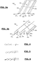
- FIGURES 3a and 3b are schematic representations of a third embodiment, in no way limiting, of the flexible cover element according to the invention.
- the flexible and transparent cover element 300 is shown in the FIGURE 3a flat, and on the FIGURE 3b in its configuration of attachment to a frame (not shown in the FIGURE 1b ) two juxtaposed culture shelters, identical or different, each having a ridge line, namely 302 1 and 302 2 .
- the covering element 300 comprises on a longitudinal edge 304 a series of two fixing openings 304 1 and 304 2 and on the opposite longitudinal edge 306 a series of three fixing openings 306 1 -306 3 .
- the fixing openings 304 1 and 304 2 make it possible to make an adjustment of the tension applied to the cover element 300 on the edge side 304 and the fixing openings 306 1 -306 3 make it possible to make an adjustment of the tension applied to the covering element 300 on the edge side 306.
- the covering element 300 comprises, at an intermediate zone 308, lying between the longitudinal edges 304 and 306, a series of three fixing openings, 308 1 -308 3 offset from one another in a direction perpendicular to the edges 304 and 306, so that the fixing opening 308 1 is closer to the edge 304, the fixing opening 308 3 is located near the edge 306 and the fixing opening 308 2 is between the fixing openings 308 1 and 308 3 .
- the covering element is used to cover the framework of two juxtaposed culture shelters, identical or similar.
- the fixing openings 308 1 -308 3 of the zone 308 are located between the juxtaposed shelters. These fixing openings 308 1 -308 3 make it possible to fix a part of the cover element 300 on one of the juxtaposed shelters and the remaining part of the cover element 300 on the other of the juxtaposed shelters.
- the fixing openings 308 1 -308 3 make it possible to adjust the tension applied to each of the parts of the cover element 300 independently of the other part.
- each culture shelter can benefit from a cover element whose tension is different.
- cover element 300 may comprise several intermediate zones each comprising one or more fixing openings.
- the covering element is in the form of a plastic sheet, for example transparent, made for example of polyethylene, for example of thickness between 80 ⁇ m and 300 ⁇ m, of width between 6.5 m and 10m, length between 15 and 120m.
- each of the fixing openings can be different.
- the width of each of the fixing openings is identical, for example between 2cm and 6cm, in particular 4cm.
- the spacing between two juxtaposed openings of the same series, considered in pairs, may be different.
- the spacing between two juxtaposed openings of the same series, considered two to two can be constant or identical, for example between 2cm and 6cm, in particular 4cm.
- each fixing opening shown in the FIGURES is in a continuous form, extending substantially over the entire length of the longitudinal edge of the covering element.
- at least one, in particular each, fixing opening may be discontinuous.
- a discontinuous attachment opening may be formed by one or more rings aligned and spaced apart.
- the FIGURE 4 is a schematic representation of a first embodiment of a fixing opening.
- the fixing openings shown on the FIGURE 4 are obtained by folding, inward or outward, the cover member on itself at the longitudinal edge of the cover member.
- the folded part is then bonded to the rest of the covering element, along a longitudinal, continuous or discontinuous bonding line. Bonding is preferably done by heating the cover element and compressing the folded part over the rest of the cover element.
- the folded part can have a width chosen by the user, for example of the order of 1 meter. More generally, the folded part may have a free end whose position on the structure can be modified by the user.
- the FIGURE 5 is a schematic representation of a second embodiment of a fixing opening.
- the cover element is made by two layers connected to each other continuously.
- the fixing openings are obtained by gluing, along a line of longitudinal bonding, continuous or discontinuous, of the two layers together. Bonding is preferably done by heating and compressing the two layers together.
- the FIGURE 6 is a schematic representation of a third embodiment of a fixing opening.
- the cover element is produced by two layers independent of each other.
- the fixing openings are obtained by bonding, along a longitudinal, continuous or discontinuous bonding line, the two layers together. Bonding is preferably done by heating and compressing the two layers together.
- FIGURE 7 is a partial schematic representation of an exemplary embodiment of a culture shelter according to the invention.
- the 700 culture shelter shown on the FIGURE 7 is a multi-chapel cultivation shelter and has a frame 702.
- the frame 702 comprises on each longitudinal side of the shelter 700, a gutter 704. On the FIGURE 7 only a channel 704 is shown.
- the frame 702 also comprises a plurality of trusses 706 arranged parallel to each other and aligned in the longitudinal direction of the shelter, materialized by the arrow 708.
- the cultivation shelter 700 comprises a flexible and transparent covering element which can be any of the covering elements 100, 200 or 300 previously described.
- the culture shelter 700 is shown with the cover element 200 of the FIGURE 2 .
- the covering element 200 is fixed to the frame 702 by means of elongated fixing elements 710, identical to each other and which can be assembled together at their adjacent ends, by screwing a elongated fixing element 700 into the fastening element adjacent longiform.
- elongated fixing elements 710 identical to each other and which can be assembled together at their adjacent ends, by screwing a elongated fixing element 700 into the fastening element adjacent longiform.
- the longiform fixing elements 710 are shown unassembled for more details of representation.
- the gutter has hooks or fixing lugs 712 integral with said gutter 712.
- Each fixing lug 712 is slightly bent downwards so as to maintain the elongated fixing element 710 once the latter has been positioned under said fixing lug 712.
- each fixing lug 712 has a sharp end in order to make a hole passing through the covering element 200.
- the fixing of the cover element on the frame 702 is carried out as follows.
- the longiform fixing elements 710 are passed through the fixing opening 206 2 of the edge 206 of the covering element 200. Once passed through the fixing opening 206 3, the longiform fixing elements are screwed together. Then, pressure is applied, for example by an operator using his foot, on each fastening element 710 to pass said elongated fastening element 210 under the fastening tabs 712. In doing so, the fastening tab 712 is forced to pierce through and pass through the cover member 200. Once positioned under the fixing tab 712, the elongated fixing element 710 is held firmly under said fixing tab 712 under the effect of the tension of the covering element 200. This operation is carried out for each tab of fastener 712 and each elongated fastening element 710 along each of the sides of the culture shelter 700.
- FIGURE 8 is a schematic representation of a fourth embodiment, in no way limiting, of the flexible cover element according to the invention.
- the flexible and transparent cover element 800 is shown in the FIGURE 8 includes all the features of the cover element 100 of the FIGURE 1 .
- the cover element 800 comprises at one of its transverse edges, namely the transverse edge 802, perpendicular to its longitudinal edges 104 and 106, a transverse fixing opening 802 1 perpendicular to the longitudinal edges 104 and 106 and to the longitudinal fixing openings 104 1 , 106 1 and 106 2 , and designed to accommodate a elongated fixing element (not shown), such as a tube or a bar, for example made of metal .
- the covering element 800 comprises on the opposite transverse edge, namely the edge 804, a series of two transverse fixing openings, namely the transverse fixing openings 804 1 and 804 2 , perpendicular to the longitudinal edges 104 and 106 and to the longitudinal fixing openings 104 1 , 106 1 and 106 2 .
- These transverse fixing openings 804 1 and 804 2 are offset with respect to each other in a direction perpendicular to the transverse edge 804, so that the transverse fixing opening 804 1 is closer to the transverse edge 804 compared at the fixing opening 804 2 .
- Each of the transverse fixing openings 804 1 and 804 2 is designed to receive a elongated fixing element (not shown).
- the numbers of transverse fixing openings can be different.
Landscapes
- Life Sciences & Earth Sciences (AREA)
- Environmental Sciences (AREA)
- Apparatus Associated With Microorganisms And Enzymes (AREA)
- Cultivation Receptacles Or Flower-Pots, Or Pots For Seedlings (AREA)
- Protection Of Plants (AREA)
Claims (14)
- Flexibles Abdeckelement (100, 200, 300) für ein Treibhaus-artiges Gewächshaus (700), das zur Befestigung an einer Unterkonstruktion (702) des Gewächshauses (700) an mindestens einer seiner Längskanten (104, 106; 204, 206; 304, 306) vorgesehen ist, dadurch gekennzeichnet, dass es an mindestens einer der Längskanten (106; 204, 206; 304, 306) eine Reihe von mindestens zwei sogenannten Befestigungsöffnungen (1061, 1062; 2041, 2042, 2061-2063; 3041, 3042; 3061-3063) umfasst, welche in einer Richtung senkrecht zur Längskante (106; 204, 206, 304, 306) versetzt angeordnet und jeweils dafür vorgesehen sind, wahlweise ein langförmiges Befestigungselement (710) derart aufzunehmen, sodass die Spannung des Abdeckelements in Abhängigkeit von der verwendeten Befestigungsöffnung eingestellt wird.
- Abdeckelement (100) nach Anspruch 1, dadurch gekennzeichnet, dass es zur Befestigung an der Unterkonstruktion (702) des Gewächshauses (700) an zwei gegenüberliegenden Längskanten (104, 106) vorgesehen ist, wobei das Abdeckelement (100) umfasst:- an einer der gegenüberliegenden Längskanten (106), eine Reihe von mindestens zwei Befestigungsöffnungen (1061, 1062), die in einer Richtung senkrecht zur Längskante (106) derart versetzt angeordnet sind, sodass die Spannung des Abdeckelements in Abhängigkeit von der verwendeten Befestigungsöffnung eingestellt wird; und- an der anderen der gegenüberliegenden Längskanten (104), eine einzelne Befestigungsöffnung (1041);jeweils (1041, 1061, 1062) dafür vorgesehen, ein langförmiges Befestigungselement aufzunehmen (710).
- Abdeckelement (200, 300) nach Anspruch 1, dadurch gekennzeichnet, dass es zur Befestigung an der Unterkonstruktion (702) des Gewächshauses (700) an zwei gegenüberliegenden Längskanten (204, 206; 304, 306) vorgesehen ist, wobei das Abdeckelement (200, 300) an jeder der gegenüberliegenden Längskanten (204, 206; 304, 306) eine Reihe von mindestens zwei Befestigungsöffnungen (2041, 2042; 2061-2063; 3041, 3042; 3061-3063) umfasst, die in einer Richtung senkrecht zur Längskante (204, 206; 304, 306) versetzt angeordnet und jeweils dafür vorgesehen sind, ein langförmiges Befestigungselement (710) derart aufzunehmen, sodass die Spannung des Abdeckelements in Abhängigkeit von der verwendeten Befestigungsöffnung eingestellt wird.
- Abdeckelement (300) nach einem der vorhergehenden Ansprüche, dadurch gekennzeichnet, dass es außerdem an mindestens einem sogenannten Zwischenbereich (308) zwischen seinen zwei Längskanten (304, 306) eine Befestigungsöffnung oder eine Reihe von mindestens zwei Befestigungsöffnungen (3081-3083) umfasst.
- Abdeckelement nach einem der vorhergehenden Ansprüche, dadurch gekennzeichnet, dass mindestens eine Befestigungsöffnung durch Zurückfaltung des Abdeckelements auf sich selbst an einer Kante des Abdeckelements und durch Kleben des zurückgefalteten Teilbereichs auf dem restlichen Abdeckelement entlang einer durchgezogenen oder unterbrochenen Klebelinie gebildet ist.
- Abdeckelement nach einem der vorhergehenden Ansprüche, dadurch gekennzeichnet, dass es zumindest teilweise durch Zusammenfügen von mindestens zwei flexiblen Abdeckfolien ausgebildet ist, wobei mindestens eine Befestigungsöffnung durch Kleben von zwei der Folien miteinander entlang einer länglichen, durchgezogenen oder unterbrochenen Klebelinie gebildet ist.
- Abdeckelement nach einem der vorhergehenden Ansprüche, dadurch gekennzeichnet, dass mindestens eine Befestigungsöffnung durch Kleben auf dem Abdeckelement von mindestens einem Ring bzw. einer Reihe von miteinander fluchtenden Ringen gebildet ist, welche unabhängig von dem Abdeckelement ausgebildet ist/sind.
- Abdeckelement nach einem der vorhergehenden Ansprüche, dadurch gekennzeichnet, dass für wenigstens eine Reihe von mindestens zwei Befestigungsöffnungen:- mindestens zwei Befestigungsöffnungen der Reihe eine gleiche oder unterschiedliche Größe aufweisen; und/oder- die Befestigungsöffnungen der Reihe in einem konstanten oder variablen Abstand versetzt voneinander angeordnet sind.
- Abdeckelement nach einem der Ansprüche 3 bis 8, dadurch gekennzeichnet, dass:- mindestens eine Befestigungsöffnung einer Reihe, welche auf der Seite einer Kante gelagert ist, eine Größe aufweist, die gleich der Größe von mindestens einer Befestigungsöffnung einer Reihe auf der Seite der anderen Kante ist oder von dieser abweicht; und/oder- mindestens zwei Befestigungsöffnungen einer Reihe, welche auf der Seite einer Kante gelagert ist, unter einander einen Abstand aufweisen, der gleich dem Abstand zwischen mindestens zwei Befestigungsöffnungen einer Reihe auf der Seite der anderen Kante ist oder von diesem Abstand abweicht.
- Abdeckelement nach einem der vorhergehenden Ansprüche, dadurch gekennzeichnet, dass:- mindestens eine Befestigungsöffnung eine Breite von 2 bis 6 cm aufweist; und/oder- mindestens zwei Befestigungsöffnungen einer Reihe unter einander einen Abstand von 2 bis 6 cm aufweisen.
- Abdeckelement (200, 300) nach einem der Ansprüche 3 bis 10, dadurch gekennzeichnet, dass es eine Anzahl von 2 bis 4 Befestigungsöffnungen für jede Reihe auf der Seite der jeweiligen gegenüberliegenden Längskanten (204, 206; 304, 306) umfasst.
- Abdecksatz für ein Treibhaus-artiges Gewächshaus (700), umfassend:- ein Abdeckelement (100, 200, 300) nach einem der vorhergehenden Ansprüche, und- mindestens ein, insbesondere mehrere langförmige Befestigungselement(e) (710), welche zur Befestigung des Abdeckelements (100, 200, 300) an einer Unterkonstruktion (702) des Gewächshauses (700) vorgesehen ist/sind.
- Treibhaus-artiges Gewächshaus (700), umfassend:- eine insbesondere starre Unterkonstruktion (702), und- mindestens einen Abdecksatz nach dem vorhergehenden Anspruch oder mindestens ein flexibles Abdeckelement (100, 200, 300) nach einem der Ansprüche 1 bis 11.
- Gewächshaus (700) nach dem vorhergehenden Anspruch, dadurch gekennzeichnet, dass die Unterkonstruktion (702) auf der Seite mindestens einer, insbesondere jeder der länglichen Seitenflächen des Gewächshauses (700) mehrere Befestigungslaschen (712) umfasst, welche längs aneinander in der Flucht, im Wesentlichen auf der gesamten Länge der Seitenfläche angeordnet sind und dafür vorgesehen sind, das oder die langförmige(n) Befestigungselement(e) (710) zu halten, welche vorab durch eine Befestigungsöffnung (2062) geführt wurden.
Applications Claiming Priority (2)
| Application Number | Priority Date | Filing Date | Title |
|---|---|---|---|
| FR1554996A FR3036921B1 (fr) | 2015-06-02 | 2015-06-02 | Element de couverture souple pour abri de culture, abri de culture muni d'un tel element de couverture. |
| PCT/EP2016/062353 WO2016193293A1 (fr) | 2015-06-02 | 2016-06-01 | Element de couverture souple pour abri de culture, abri de culture muni d'un tel element de couverture |
Publications (2)
| Publication Number | Publication Date |
|---|---|
| EP3302028A1 EP3302028A1 (de) | 2018-04-11 |
| EP3302028B1 true EP3302028B1 (de) | 2020-03-25 |
Family
ID=54014997
Family Applications (1)
| Application Number | Title | Priority Date | Filing Date |
|---|---|---|---|
| EP16732453.2A Active EP3302028B1 (de) | 2015-06-02 | 2016-06-01 | Flexibles abdeckelement für ein gewächshaus, mit solch einem abdeckelement ausgestattetes gewächshaus |
Country Status (4)
| Country | Link |
|---|---|
| EP (1) | EP3302028B1 (de) |
| ES (1) | ES2784604T3 (de) |
| FR (1) | FR3036921B1 (de) |
| WO (1) | WO2016193293A1 (de) |
Family Cites Families (4)
| Publication number | Priority date | Publication date | Assignee | Title |
|---|---|---|---|---|
| AU502006B2 (en) * | 1974-09-25 | 1979-07-12 | Bennett, Peter Reginald Dane | Cover for seedlings |
| FR2569523A1 (fr) * | 1984-09-06 | 1986-03-07 | Ortiz Antoine | Chassis-serre ameliore |
| BE902321A (nl) * | 1985-04-30 | 1985-08-16 | Ferket Wim | Serre of broeikas. |
| FR2838287B1 (fr) * | 2002-04-15 | 2005-04-15 | Patrick Fortier | Serres, films pour couverture de serres et procede pour tendre ou retendre des films de serres |
-
2015
- 2015-06-02 FR FR1554996A patent/FR3036921B1/fr active Active
-
2016
- 2016-06-01 WO PCT/EP2016/062353 patent/WO2016193293A1/fr not_active Ceased
- 2016-06-01 ES ES16732453T patent/ES2784604T3/es active Active
- 2016-06-01 EP EP16732453.2A patent/EP3302028B1/de active Active
Non-Patent Citations (1)
| Title |
|---|
| None * |
Also Published As
| Publication number | Publication date |
|---|---|
| WO2016193293A1 (fr) | 2016-12-08 |
| FR3036921A1 (fr) | 2016-12-09 |
| EP3302028A1 (de) | 2018-04-11 |
| ES2784604T3 (es) | 2020-09-29 |
| FR3036921B1 (fr) | 2018-04-06 |
Similar Documents
| Publication | Publication Date | Title |
|---|---|---|
| WO2013160457A1 (fr) | Dispositif de revêtement d'une structure de bâtiment et structure revêtue par un tel dispositif | |
| EP3302028B1 (de) | Flexibles abdeckelement für ein gewächshaus, mit solch einem abdeckelement ausgestattetes gewächshaus | |
| EP1230839A1 (de) | Anlage zum Aufbinden, insbesondere der Reben | |
| EP3369877B1 (de) | Rahmen umfassend eine rahmenstruktur, ein gewebe und eine vorrichtung zum befestigen des gewebes auf einem profil der rahmenstruktur | |
| FR2488486A1 (fr) | Cloches et cadres de cloche notamment pour l'agriculture | |
| EP3402724B1 (de) | Behälter | |
| EP2428111A1 (de) | Halterung für Fadengeber auf Profilstab mit Sperrhebeln | |
| FR2931631A1 (fr) | Dispositif permettant de reduire la prise au vent de la toile de protection d'un parasol ou autre abri | |
| EP1891294B1 (de) | Türabdeckung | |
| EP3931413B1 (de) | Verankerungsvorrichtung zur verankerung eines pfahls eines strandsonnenschirms im sand oder sandigen boden | |
| EP1646792A1 (de) | Profilleiste zur befestigung eines gespannten tuchs | |
| EP2950677B1 (de) | Dekorelement mit einer anzahl von in einem geschlossenen rahmen angeordneten steinen und zwei dekorativen flächen | |
| FR3077464A1 (fr) | Bache pour la culture vegetale. | |
| EP2236052A1 (de) | Schirm | |
| FR3019754A1 (fr) | Dispositif anti-recul pour la pratique du ski de randonnee | |
| WO2017001527A1 (fr) | Dispositif de fixation d'element(s) de couverture pour abri de culture, abri de culture muni de tels dispositifs | |
| FR3013943A1 (fr) | Bache de couverture pour la culture des plantes a aerations preformees. | |
| FR2985413A1 (fr) | Lame d'outil de scarification de pate, notamment de pate a pain. | |
| EP2875722A1 (de) | Stützpfahl für Weinrebe | |
| FR2919462A1 (fr) | Tuteur pour plantes vegetales en forme de treillis horizontal destine a tenir dressees et regulierement espacees entre elles les tiges des plantes ou des fleurs de grande taille cultivees dans les jardins ou les serres. | |
| EP3034139A1 (de) | Halterungsvorrichtung eines schuhes auf einem gleitbrett | |
| WO2023041887A1 (fr) | Parasol comportant une structure souple | |
| FR2797150A1 (fr) | Piege englue contre les mouches des arbres fruitiers | |
| EP4530430A1 (de) | Vorrichtung zum halten von endkappen von rolladenblättern | |
| FR2542180A1 (fr) | Dispositif pour fixer de facon amovible un coussin sur le dossier et/ou l'assise d'un siege |
Legal Events
| Date | Code | Title | Description |
|---|---|---|---|
| STAA | Information on the status of an ep patent application or granted ep patent |
Free format text: STATUS: THE INTERNATIONAL PUBLICATION HAS BEEN MADE |
|
| PUAI | Public reference made under article 153(3) epc to a published international application that has entered the european phase |
Free format text: ORIGINAL CODE: 0009012 |
|
| STAA | Information on the status of an ep patent application or granted ep patent |
Free format text: STATUS: REQUEST FOR EXAMINATION WAS MADE |
|
| 17P | Request for examination filed |
Effective date: 20171201 |
|
| AK | Designated contracting states |
Kind code of ref document: A1 Designated state(s): AL AT BE BG CH CY CZ DE DK EE ES FI FR GB GR HR HU IE IS IT LI LT LU LV MC MK MT NL NO PL PT RO RS SE SI SK SM TR |
|
| AX | Request for extension of the european patent |
Extension state: BA ME |
|
| DAV | Request for validation of the european patent (deleted) | ||
| DAX | Request for extension of the european patent (deleted) | ||
| GRAP | Despatch of communication of intention to grant a patent |
Free format text: ORIGINAL CODE: EPIDOSNIGR1 |
|
| STAA | Information on the status of an ep patent application or granted ep patent |
Free format text: STATUS: GRANT OF PATENT IS INTENDED |
|
| INTG | Intention to grant announced |
Effective date: 20191120 |
|
| GRAS | Grant fee paid |
Free format text: ORIGINAL CODE: EPIDOSNIGR3 |
|
| GRAA | (expected) grant |
Free format text: ORIGINAL CODE: 0009210 |
|
| STAA | Information on the status of an ep patent application or granted ep patent |
Free format text: STATUS: THE PATENT HAS BEEN GRANTED |
|
| AK | Designated contracting states |
Kind code of ref document: B1 Designated state(s): AL AT BE BG CH CY CZ DE DK EE ES FI FR GB GR HR HU IE IS IT LI LT LU LV MC MK MT NL NO PL PT RO RS SE SI SK SM TR |
|
| REG | Reference to a national code |
Ref country code: GB Ref legal event code: FG4D Free format text: NOT ENGLISH |
|
| REG | Reference to a national code |
Ref country code: AT Ref legal event code: REF Ref document number: 1247452 Country of ref document: AT Kind code of ref document: T Effective date: 20200415 Ref country code: IE Ref legal event code: FG4D Free format text: LANGUAGE OF EP DOCUMENT: FRENCH |
|
| REG | Reference to a national code |
Ref country code: DE Ref legal event code: R096 Ref document number: 602016032520 Country of ref document: DE |
|
| PG25 | Lapsed in a contracting state [announced via postgrant information from national office to epo] |
Ref country code: RS Free format text: LAPSE BECAUSE OF FAILURE TO SUBMIT A TRANSLATION OF THE DESCRIPTION OR TO PAY THE FEE WITHIN THE PRESCRIBED TIME-LIMIT Effective date: 20200325 Ref country code: FI Free format text: LAPSE BECAUSE OF FAILURE TO SUBMIT A TRANSLATION OF THE DESCRIPTION OR TO PAY THE FEE WITHIN THE PRESCRIBED TIME-LIMIT Effective date: 20200325 Ref country code: NO Free format text: LAPSE BECAUSE OF FAILURE TO SUBMIT A TRANSLATION OF THE DESCRIPTION OR TO PAY THE FEE WITHIN THE PRESCRIBED TIME-LIMIT Effective date: 20200625 |
|
| PG25 | Lapsed in a contracting state [announced via postgrant information from national office to epo] |
Ref country code: BG Free format text: LAPSE BECAUSE OF FAILURE TO SUBMIT A TRANSLATION OF THE DESCRIPTION OR TO PAY THE FEE WITHIN THE PRESCRIBED TIME-LIMIT Effective date: 20200625 Ref country code: HR Free format text: LAPSE BECAUSE OF FAILURE TO SUBMIT A TRANSLATION OF THE DESCRIPTION OR TO PAY THE FEE WITHIN THE PRESCRIBED TIME-LIMIT Effective date: 20200325 Ref country code: GR Free format text: LAPSE BECAUSE OF FAILURE TO SUBMIT A TRANSLATION OF THE DESCRIPTION OR TO PAY THE FEE WITHIN THE PRESCRIBED TIME-LIMIT Effective date: 20200626 Ref country code: LV Free format text: LAPSE BECAUSE OF FAILURE TO SUBMIT A TRANSLATION OF THE DESCRIPTION OR TO PAY THE FEE WITHIN THE PRESCRIBED TIME-LIMIT Effective date: 20200325 Ref country code: SE Free format text: LAPSE BECAUSE OF FAILURE TO SUBMIT A TRANSLATION OF THE DESCRIPTION OR TO PAY THE FEE WITHIN THE PRESCRIBED TIME-LIMIT Effective date: 20200325 |
|
| REG | Reference to a national code |
Ref country code: NL Ref legal event code: MP Effective date: 20200325 |
|
| REG | Reference to a national code |
Ref country code: LT Ref legal event code: MG4D |
|
| REG | Reference to a national code |
Ref country code: ES Ref legal event code: FG2A Ref document number: 2784604 Country of ref document: ES Kind code of ref document: T3 Effective date: 20200929 |
|
| PG25 | Lapsed in a contracting state [announced via postgrant information from national office to epo] |
Ref country code: NL Free format text: LAPSE BECAUSE OF FAILURE TO SUBMIT A TRANSLATION OF THE DESCRIPTION OR TO PAY THE FEE WITHIN THE PRESCRIBED TIME-LIMIT Effective date: 20200325 |
|
| PG25 | Lapsed in a contracting state [announced via postgrant information from national office to epo] |
Ref country code: PT Free format text: LAPSE BECAUSE OF FAILURE TO SUBMIT A TRANSLATION OF THE DESCRIPTION OR TO PAY THE FEE WITHIN THE PRESCRIBED TIME-LIMIT Effective date: 20200818 Ref country code: SM Free format text: LAPSE BECAUSE OF FAILURE TO SUBMIT A TRANSLATION OF THE DESCRIPTION OR TO PAY THE FEE WITHIN THE PRESCRIBED TIME-LIMIT Effective date: 20200325 Ref country code: EE Free format text: LAPSE BECAUSE OF FAILURE TO SUBMIT A TRANSLATION OF THE DESCRIPTION OR TO PAY THE FEE WITHIN THE PRESCRIBED TIME-LIMIT Effective date: 20200325 Ref country code: SK Free format text: LAPSE BECAUSE OF FAILURE TO SUBMIT A TRANSLATION OF THE DESCRIPTION OR TO PAY THE FEE WITHIN THE PRESCRIBED TIME-LIMIT Effective date: 20200325 Ref country code: CZ Free format text: LAPSE BECAUSE OF FAILURE TO SUBMIT A TRANSLATION OF THE DESCRIPTION OR TO PAY THE FEE WITHIN THE PRESCRIBED TIME-LIMIT Effective date: 20200325 Ref country code: IS Free format text: LAPSE BECAUSE OF FAILURE TO SUBMIT A TRANSLATION OF THE DESCRIPTION OR TO PAY THE FEE WITHIN THE PRESCRIBED TIME-LIMIT Effective date: 20200725 Ref country code: RO Free format text: LAPSE BECAUSE OF FAILURE TO SUBMIT A TRANSLATION OF THE DESCRIPTION OR TO PAY THE FEE WITHIN THE PRESCRIBED TIME-LIMIT Effective date: 20200325 Ref country code: LT Free format text: LAPSE BECAUSE OF FAILURE TO SUBMIT A TRANSLATION OF THE DESCRIPTION OR TO PAY THE FEE WITHIN THE PRESCRIBED TIME-LIMIT Effective date: 20200325 |
|
| REG | Reference to a national code |
Ref country code: AT Ref legal event code: MK05 Ref document number: 1247452 Country of ref document: AT Kind code of ref document: T Effective date: 20200325 |
|
| REG | Reference to a national code |
Ref country code: DE Ref legal event code: R119 Ref document number: 602016032520 Country of ref document: DE |
|
| PG25 | Lapsed in a contracting state [announced via postgrant information from national office to epo] |
Ref country code: IT Free format text: LAPSE BECAUSE OF FAILURE TO SUBMIT A TRANSLATION OF THE DESCRIPTION OR TO PAY THE FEE WITHIN THE PRESCRIBED TIME-LIMIT Effective date: 20200325 Ref country code: AT Free format text: LAPSE BECAUSE OF FAILURE TO SUBMIT A TRANSLATION OF THE DESCRIPTION OR TO PAY THE FEE WITHIN THE PRESCRIBED TIME-LIMIT Effective date: 20200325 Ref country code: DK Free format text: LAPSE BECAUSE OF FAILURE TO SUBMIT A TRANSLATION OF THE DESCRIPTION OR TO PAY THE FEE WITHIN THE PRESCRIBED TIME-LIMIT Effective date: 20200325 Ref country code: MC Free format text: LAPSE BECAUSE OF FAILURE TO SUBMIT A TRANSLATION OF THE DESCRIPTION OR TO PAY THE FEE WITHIN THE PRESCRIBED TIME-LIMIT Effective date: 20200325 |
|
| REG | Reference to a national code |
Ref country code: CH Ref legal event code: PL |
|
| PLBE | No opposition filed within time limit |
Free format text: ORIGINAL CODE: 0009261 |
|
| STAA | Information on the status of an ep patent application or granted ep patent |
Free format text: STATUS: NO OPPOSITION FILED WITHIN TIME LIMIT |
|
| PG25 | Lapsed in a contracting state [announced via postgrant information from national office to epo] |
Ref country code: PL Free format text: LAPSE BECAUSE OF FAILURE TO SUBMIT A TRANSLATION OF THE DESCRIPTION OR TO PAY THE FEE WITHIN THE PRESCRIBED TIME-LIMIT Effective date: 20200325 |
|
| 26N | No opposition filed |
Effective date: 20210112 |
|
| GBPC | Gb: european patent ceased through non-payment of renewal fee |
Effective date: 20200625 |
|
| PG25 | Lapsed in a contracting state [announced via postgrant information from national office to epo] |
Ref country code: LU Free format text: LAPSE BECAUSE OF NON-PAYMENT OF DUE FEES Effective date: 20200601 |
|
| REG | Reference to a national code |
Ref country code: BE Ref legal event code: MM Effective date: 20200630 |
|
| PG25 | Lapsed in a contracting state [announced via postgrant information from national office to epo] |
Ref country code: IE Free format text: LAPSE BECAUSE OF NON-PAYMENT OF DUE FEES Effective date: 20200601 Ref country code: GB Free format text: LAPSE BECAUSE OF NON-PAYMENT OF DUE FEES Effective date: 20200625 Ref country code: CH Free format text: LAPSE BECAUSE OF NON-PAYMENT OF DUE FEES Effective date: 20200630 Ref country code: LI Free format text: LAPSE BECAUSE OF NON-PAYMENT OF DUE FEES Effective date: 20200630 |
|
| PG25 | Lapsed in a contracting state [announced via postgrant information from national office to epo] |
Ref country code: BE Free format text: LAPSE BECAUSE OF NON-PAYMENT OF DUE FEES Effective date: 20200630 Ref country code: DE Free format text: LAPSE BECAUSE OF NON-PAYMENT OF DUE FEES Effective date: 20210101 Ref country code: SI Free format text: LAPSE BECAUSE OF FAILURE TO SUBMIT A TRANSLATION OF THE DESCRIPTION OR TO PAY THE FEE WITHIN THE PRESCRIBED TIME-LIMIT Effective date: 20200325 |
|
| PG25 | Lapsed in a contracting state [announced via postgrant information from national office to epo] |
Ref country code: TR Free format text: LAPSE BECAUSE OF FAILURE TO SUBMIT A TRANSLATION OF THE DESCRIPTION OR TO PAY THE FEE WITHIN THE PRESCRIBED TIME-LIMIT Effective date: 20200325 Ref country code: MT Free format text: LAPSE BECAUSE OF FAILURE TO SUBMIT A TRANSLATION OF THE DESCRIPTION OR TO PAY THE FEE WITHIN THE PRESCRIBED TIME-LIMIT Effective date: 20200325 Ref country code: CY Free format text: LAPSE BECAUSE OF FAILURE TO SUBMIT A TRANSLATION OF THE DESCRIPTION OR TO PAY THE FEE WITHIN THE PRESCRIBED TIME-LIMIT Effective date: 20200325 |
|
| PG25 | Lapsed in a contracting state [announced via postgrant information from national office to epo] |
Ref country code: MK Free format text: LAPSE BECAUSE OF FAILURE TO SUBMIT A TRANSLATION OF THE DESCRIPTION OR TO PAY THE FEE WITHIN THE PRESCRIBED TIME-LIMIT Effective date: 20200325 Ref country code: AL Free format text: LAPSE BECAUSE OF FAILURE TO SUBMIT A TRANSLATION OF THE DESCRIPTION OR TO PAY THE FEE WITHIN THE PRESCRIBED TIME-LIMIT Effective date: 20200325 |
|
| P01 | Opt-out of the competence of the unified patent court (upc) registered |
Effective date: 20230512 |
|
| PGFP | Annual fee paid to national office [announced via postgrant information from national office to epo] |
Ref country code: FR Payment date: 20250627 Year of fee payment: 10 |
|
| PGFP | Annual fee paid to national office [announced via postgrant information from national office to epo] |
Ref country code: ES Payment date: 20250828 Year of fee payment: 10 |