EP3931413B1 - Verankerungsvorrichtung zur verankerung eines pfahls eines strandsonnenschirms im sand oder sandigen boden - Google Patents
Verankerungsvorrichtung zur verankerung eines pfahls eines strandsonnenschirms im sand oder sandigen boden Download PDFInfo
- Publication number
- EP3931413B1 EP3931413B1 EP20706737.2A EP20706737A EP3931413B1 EP 3931413 B1 EP3931413 B1 EP 3931413B1 EP 20706737 A EP20706737 A EP 20706737A EP 3931413 B1 EP3931413 B1 EP 3931413B1
- Authority
- EP
- European Patent Office
- Prior art keywords
- wall
- plate
- sleeve
- anchoring device
- buriable
- Prior art date
- Legal status (The legal status is an assumption and is not a legal conclusion. Google has not performed a legal analysis and makes no representation as to the accuracy of the status listed.)
- Active
Links
- 239000004576 sand Substances 0.000 title claims description 47
- 238000004873 anchoring Methods 0.000 title claims description 32
- 239000002689 soil Substances 0.000 title claims description 8
- 239000000463 material Substances 0.000 claims description 10
- 229920001971 elastomer Polymers 0.000 claims description 8
- 238000004519 manufacturing process Methods 0.000 claims description 8
- 239000000806 elastomer Substances 0.000 claims description 6
- 238000000465 moulding Methods 0.000 claims description 5
- 238000000034 method Methods 0.000 claims description 4
- 239000004744 fabric Substances 0.000 claims description 3
- 239000012528 membrane Substances 0.000 description 7
- 230000000694 effects Effects 0.000 description 6
- 238000003780 insertion Methods 0.000 description 4
- 230000037431 insertion Effects 0.000 description 4
- 229920002943 EPDM rubber Polymers 0.000 description 2
- 241001508691 Martes zibellina Species 0.000 description 2
- 238000005452 bending Methods 0.000 description 2
- 238000009933 burial Methods 0.000 description 2
- 239000000470 constituent Substances 0.000 description 2
- 239000004033 plastic Substances 0.000 description 2
- 229920000728 polyester Polymers 0.000 description 2
- 239000000243 solution Substances 0.000 description 2
- 239000004743 Polypropylene Substances 0.000 description 1
- 239000000853 adhesive Substances 0.000 description 1
- 230000001070 adhesive effect Effects 0.000 description 1
- 238000013459 approach Methods 0.000 description 1
- 238000009412 basement excavation Methods 0.000 description 1
- 238000006073 displacement reaction Methods 0.000 description 1
- 239000000835 fiber Substances 0.000 description 1
- 239000012530 fluid Substances 0.000 description 1
- 238000002347 injection Methods 0.000 description 1
- 239000007924 injection Substances 0.000 description 1
- 230000014759 maintenance of location Effects 0.000 description 1
- 150000002825 nitriles Chemical class 0.000 description 1
- -1 polypropylene Polymers 0.000 description 1
- 229920001155 polypropylene Polymers 0.000 description 1
- 229920001296 polysiloxane Polymers 0.000 description 1
- 230000003014 reinforcing effect Effects 0.000 description 1
- 238000000926 separation method Methods 0.000 description 1
- 230000001131 transforming effect Effects 0.000 description 1
- 239000002759 woven fabric Substances 0.000 description 1
Images


Classifications
-
- E—FIXED CONSTRUCTIONS
- E04—BUILDING
- E04H—BUILDINGS OR LIKE STRUCTURES FOR PARTICULAR PURPOSES; SWIMMING OR SPLASH BATHS OR POOLS; MASTS; FENCING; TENTS OR CANOPIES, IN GENERAL
- E04H12/00—Towers; Masts or poles; Chimney stacks; Water-towers; Methods of erecting such structures
- E04H12/22—Sockets or holders for poles or posts
- E04H12/2253—Mounting poles or posts to the holder
- E04H12/2261—Mounting poles or posts to the holder on a flat base
-
- A—HUMAN NECESSITIES
- A45—HAND OR TRAVELLING ARTICLES
- A45B—WALKING STICKS; UMBRELLAS; LADIES' OR LIKE FANS
- A45B25/00—Details of umbrellas
-
- A—HUMAN NECESSITIES
- A45—HAND OR TRAVELLING ARTICLES
- A45F—TRAVELLING OR CAMP EQUIPMENT: SACKS OR PACKS CARRIED ON THE BODY
- A45F3/00—Travelling or camp articles; Sacks or packs carried on the body
- A45F3/44—Article supports adapted to be stuck into the ground
-
- A—HUMAN NECESSITIES
- A45—HAND OR TRAVELLING ARTICLES
- A45B—WALKING STICKS; UMBRELLAS; LADIES' OR LIKE FANS
- A45B23/00—Other umbrellas
- A45B2023/0012—Ground supported umbrellas or sunshades on a single post, e.g. resting in or on a surface there below
-
- A—HUMAN NECESSITIES
- A45—HAND OR TRAVELLING ARTICLES
- A45B—WALKING STICKS; UMBRELLAS; LADIES' OR LIKE FANS
- A45B25/00—Details of umbrellas
- A45B2025/003—Accessories not covered by groups A45B25/24 - A45B25/30
Definitions
- the present invention relates to a device for anchoring in the sand or in sandy soil, a beach umbrella stake.
- this anchor for the parasol does not resist the action of the wind on the deployed canvas of the parasol. Indeed, the wind resistance of the open parasol is relatively high and all it takes is a violent gust to tear it from the sand and make it pick up speed, transforming it into a daunting projectile. Fatal accidents have occurred in recent years on French territory alone.
- a screw-on parasol base which consists of a cone surmounted by a tubular part equipped with a screw handle and a screw for tightening the tube constituting the parasol base.
- a helical thread is formed around the cone.
- the parasol base is screwed into the sand and the parasol pole is inserted into the tubular part and the pole is blocked by tightening the screw.
- the resistance to tearing of the parasol stake is improved, given the increased surface of the parasol base to be screwed in contact with the sand and the presence of the helical net, but remains however insufficient to retain it during a gust Wind.
- the support base includes a membrane and a mounting bracket.
- the membrane is disc-shaped, it is made of a woven fabric in PVC coated polyester yarn.
- the thickness of the membrane is 0.75 mm.
- the diameter of the disc is between 46 cm and 91 cm and ideally measures 60 cm.
- the mounting bracket includes an upper portion located on the upper side of the membrane and a lower portion located on the lower side of the membrane. The two parts are attached to each other or to the membrane.
- the mounting bracket is defined by a central tubular element through which there is an internal bore slightly larger than the diameter of the parasol stem and which is surrounded by an upper outer sleeve. This is fixed in the membrane by press fit, by a fixing or with an adhesive. It is made of rubber or plastic material, such as PVC.
- the upper outer sleeve is crossed by a thread in which a tightening screw makes it possible to block the stem of the parasol.
- a device for anchoring in the sand or in sandy soil, a stake for a beach umbrella, comprising a plate buried in sand made of a flexible or semi-rigid material, a sleeve intended to receive said stake, the sleeve being associated with said plate via a junction zone, the sleeve being open on both sides;
- the sleeve comprises a tubular inner wall connected to the outer wall via radial ribs, said radial ribs being extended towards the inside of the tubular inner wall to come into contact with the wall constituting the stake.
- the sleeve does not require any additional clamping device to retain the parasol pole.
- the anchor device is relatively inexpensive to manufacture.
- a tubular intermediate wall is formed between the outer wall and the tubular inner wall, the tubular intermediate wall being connected to the outer wall and to the tubular inner wall, via the radial ribs.
- the sleeve has, in front view, an outer wall in the shape of a truncated cone, the large base of which forms the junction with the buryable plate.
- This geometry of the sleeve gives it good mechanical strength and makes it possible to increase the pressure that the sand exerts around the sleeve when the anchoring device is buried.
- openings pass through the buryable plate at the level of the junction zone and radial folds delimit facets in the buryable plate in the form of angular sectors, from the sleeve to the periphery of the plate. buryable, at least one radial ply being secant with an opening.
- the openings provide flexibility in the junction area.
- the facets are thus less deformed by the inclination of the sleeve in a windy situation on the parasol. They can thus remain stable when they are kept trapped in the sand, which avoids the excavation of the buryable wall.
- the openings allow the folding of the facets in the extension of the sleeve.
- cells are formed on the upper face intended to be turned towards the top of the buryable plate.
- Studs are formed in the burial sand, which increases the pull-out resistance of the device and improves its operating safety.
- the underside of the buryable plate has a smooth appearance.
- the smooth underside provides a suction cup effect to the buryable plate with underlying wet sand.
- the buryable plate has, when it rests on a flat support, the geometry of a disc with a diameter of between 20 cm and 40 cm +/- 2 cm with a preferential value of 30 cm +/-2cm.
- the anchoring device is effective for the majority of beach umbrellas with an open canopy diameter of approximately 180 cm.
- the anchoring device includes a stake for a parasol.
- This set can accommodate a parasol pole.
- the anchoring device includes a parasol pole equipped with a fabric and a mechanism for deploying the latter.
- This set provides independent use of the parasol.
- a method of manufacturing an anchor device forms part of the invention.
- the anchoring device is manufactured by molding, the buryable plate as well as the said sleeve forming one and the same object manufactured in one piece.
- the molded anchor is ready for use. It is packaged to be offered for sale.
- the material chosen is an elastomer and whose hardness is between 60 and 90 ⁇ 8 IRHD, the thickness of the buryable plate being between 2 and 10 mm with a preferred value of 3 mm.
- a buryable plate is thus obtained which has sufficient rigidity and in particular when the buryable plate is defined by facets.
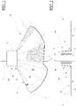
- the anchor device 100 presented on the Figs. 1, 2 and 3 , is intended to anchor, in a safe manner, the stake P constituting a parasol, in the sand of a beach or in sandy soil.
- It consists of a Pf buried plate, a Mn sleeve for receiving a P stake for a parasol.
- the buryable plate Pf is laid flat on a plane support N to simulate a burying situation.
- the buryable plate Pf in this situation preferably has the shape of a disc D so that the user of the anchoring device 100 does not have to choose its best operating orientation.
- the diameter of the disc D is between 20 cm and 40 cm +/-2 cm depending on the size of the beach umbrella with a preferential value practically equal to 30 cm +/- 2 cm, corresponding to the majority of beach umbrellas and whose diameter of the open canvas is approximately 180 cm.
- the planar buryable plate Pf is made of a flexible or preferably semi-rigid material, manually deformable but which does not undergo permanent deformation, in the register of normal use.
- the hardness of the elastomer is chosen between 60 to 90 ⁇ 8 IRHD.
- the elastomer is chosen in particular from nitrile, EPDM (abbreviation for ethylene-propylene-diene monomer), silicone, rubber.
- the elastomer chosen is preferably a regenerated polypropylene.
- a material well suited for the manufacture of this Pf plate is a flat sheet of elastomer with a thickness of between 2 mm and 10 mm. A value of 3 mm provides correct resistance and sufficient rigidity.
- the upper face of the buryable plate Pf which is intended to face upwards has cells V in order to be able to receive by molding a plurality of aggregates of grains of sand and thus increase the contact surface of said plate with the mass of sand located above her.
- its underside is smooth to provide a suction cup effect with an underlying wet sand.
- the cells V are radially aligned. They have a square geometry at the periphery of the burial plate and which evolves towards a rectangular geometry as it approaches the sleeve Mn and by delimiting between them separations of quasi-constant and relatively small thickness. A thousand cells are at least formed in the buryable plate Pf. In this way, a plurality of studs are formed by molding in the burying sand, which increases the resistance to tearing of the device and improves its operating safety. .
- the constituent material of the buryable plate Pf can incorporate a reinforcing weft T made, for example, of a plurality of crossed polyester fibers, to increase the resistance to tearing of the buryable plate Pf.
- the sleeve Mn is connected to the buryable plate Pf via a zone of a junction Zj.
- the sleeve Mn is erected perpendicularly on the upper face of the disc D and in the center thereof. It is intended to receive the part of a beach umbrella pole P which is normally intended to be driven into the ground.
- the anchor device 100 of the invention is made in an injection mold of a plastic material.
- the sleeve Mn thus forms an integral part of the anchoring device 100, that is to say that the buryable plate Pf as well as said sleeve Mn form a single and same object manufactured in a single piece.
- This embodiment is suitable for mass production.
- the sleeve Mn emerges on both sides. In front view, it has an outer wall Tc in the shape of a truncated cone Tc, the large base of which forms the junction Zj with the buryable plate Pf to provide it with good mechanical strength and increase the pressure of the sand around the sleeve Mn.
- the sleeve Mn is defined by a tubular inner wall Pt in which it is necessary to insert the stake of the parasol.
- the tubular inner wall Pt preferably has a cylindrical geometry, as shown in this Fig. 2 .
- this tubular inner wall Pt is connected to the outer wall Tc via a plurality of radial ribs Nv to accept the deformation of said tubular inner wall.
- tubular inner wall Pt can increase in size during stake insertion to accept diameter stakes of different diameters.
- a tubular intermediate wall Pti is formed between the outer wall Tc and the tubular inner wall Pt.
- This tubular intermediate wall Pti is connected to the outer wall Tc and to the tubular inner wall Pt, via the radial ribs Nv.
- the tubular intermediate wall Pti preferably has a cylindrical geometry, as shown in this Fig. 2 . The presence of this tubular intermediate wall Pti increases the stiffness of the tubular inner wall Pt.
- the radial ribs Nv are extended inside the tubular inner wall Pt and are sized to come into contact with the wall of the post P.
- These projecting parts of the ribs Nv inside the tubular inner wall Pt allow on the one hand, to facilitate the insertion of the stake by rotation in said tubular inner wall Pt by bending the projecting parts of said ribs and, on the other hand, to increase the tightening of the stake in the sleeve Mn by the relatively high pressure they exert on the wall of the post T.
- the user can turn the post P in the opposite direction in the tubular inner wall Pt to bring the projecting parts of the ribs Nv into a radial plane.
- openings Ov pass through the buryable plate Pf at the level of the junction zone Zj.
- Openings Ov are regularly distributed around the axis of the tubular intermediate wall Pt.
- radial folds Ir delimit in the buryable plate Pf facets in the form of angular sectors Sa, from the sleeve Mn to the periphery of the buryable plate Pf. At least one radial fold Ir intersects with an opening Ov.
- the facets Sa have a semi-rigid structure given the nature of the constituent material of the device 100 and given the thickness of said facets.
- Each radial ply Ir is formed by a groove of constant width dug into the thickness of the buryable wall Pf, from its upper face.
- the facets Sa thus articulated can then move to match the approximately flat relief of the sand on which said buryable wall rests.
- the facets Sa can fold around the sleeve Mn and in its extension to practically form an easily transportable cylinder.
- the anchoring device 100 can be delivered with a link, such as an elastic bracelet to keep said facets folded back.
- the V cells are formed only in the Sa facets.
- the cells are present on at least half of the surface of the Sa facets.
- the operation of the anchoring device 100 is as follows with reference to the Figs. 4 and 5 : We thread the end of a pole P of a parasol range in the inner tubular wall Pt of the sleeve Mn. The projecting parts of the radial ribs Nv then come into contact with the wall of the post P to retain it firmly in the sleeve Mn.
- the stake P can be turned in one direction in the sleeve Mn to bend the projecting parts of the radial ribs Nv.
- the end of the stake is threaded so that its tapered end protrudes from the sleeve Mn by at least ten centimeters.
- the adherence of the projecting parts of the radial ribs Nv to the tube constituting the stake T is sufficient to retain it because the pressure applied is relatively high.
- the tubular inner wall Pt as well as the tubular intermediate wall Pti can expand by longitudinally compressing the ribs Nv to accept a larger post.
- the thicknesses of the tubular inner wall Pt, of the tubular intermediate wall Pti, of the ribs Nv, the spacing between the tubular inner wall Pt and the tubular intermediate wall Pti, this tubular intermediate wall Pti and the outer wall Tc are calculated so that the sleeve Mn can accommodate and hold a T rod whose diameter is between 22 and 25 mm.
- the anchoring device 100 equipped with a stake P, is then ready to be used.
- the sand is dug at the location of the parasol to a depth of about twenty centimeters.
- the buryable wall Pf is opened and placed substantially flat on the uncovered surface of the sand, the facets Sa marrying the imperfect flatness of the sand and the buryable wall Pf is then buried, covering it with the sand B removed beforehand.
- the facets Sa of the disc D rest by their lower faces on the sand and the upper face of the buryable wall Pf is covered by a mass of sand B and which is embedded by molding in the cells V to increase the retention capacity of the sleeve in said mass of sand.
- the pole of the parasol is then mounted on the stake P anchored in the sand B.
- the stake P is thus held in the sleeve Mn secured to the buryable wall Pf which extends practically in a horizontal direction and which is held prisoner in a mass sand.
- a force F1 symbolizing the pressure of the wind on the parasol is exerted radially on the post P, the junction zone Zj is deformed, thanks to the presence of the openings Ov, under the effect of the torque exerted in the sleeve Mn by the stake P.
- the pressure exerted by the sand B on both sides of the disc D limits the deformation of the buried wall sand Pf.
- the relatively rigid geometry of the facets Sa remains stable in the sand B thanks to this flexible junction zone Zj.
- the geometry of the buried plate Pf consequently also remains stable under the constraint of the inclination of the sleeve Mn by the effect of the wind on the parasol.
- the lateral displacement of the buryable plate Pf is practically non-existent due to the relatively large surface of its two faces, upper and lower, in contact with the sand B.
- the mass of sand B located above the buryable plate Pf traps it.
- the buryable plate Pf is like taken in vice.
- sand enters the interstices present inside the sleeve Mn.
- sand can thus penetrate between the stake P and the tubular inner wall Pt, between this tubular inner wall Pt and the tubular intermediate wall Pti, between this tubular intermediate wall Pti and the outer wall Tc.
- the sand embedded in the sleeve Mn blocks the expansion of the tubular inner wall Pt and of the tubular intermediate wall Pti so that the tightening of the projecting parts of the ribs Nv on the wall of the post P is maintained in particular when the sleeve tilts under the effect of the wind on the parasol.
- the buryable plate When not in use, the buryable plate can be folded around the stake to facilitate its transport.
Claims (11)
- Verankerungsvorrichtung (100) zur Verankerung eines Pfahls (P) für einen Strandsonnenschirm im Sand oder in einem sandigen Boden, umfassend eine vergrabbare Platte (Pf), die aus einem flexiblen oder halbstarren Material hergestellt ist, eine Hülse (Mn), die dazu bestimmt ist, den Pfahl aufzunehmen, wobei die Hülse (Mn) mit der Platte über einen Übergangsbereich (Zj) zusammenhängt, wobei die Hülse (Mn) an ihren beiden Seiten offen ist, dadurch gekennzeichnet, dass die Hülse (Mn) eine rohrförmige Innenwand (Pt) umfasst, die mit der Außenwand (Tc) über radiale Rippen (Nv) verbunden ist, wobei die radialen Rippen zum Inneren der rohrförmigen Innenwand (Pt) hin verlängert sind, um mit der Wand, aus welcher der Pfahl (T) besteht, in Kontakt zu gelangen.
- Verankerungsvorrichtung (100) nach Anspruch 1, dadurch gekennzeichnet, dass eine rohrförmige Zwischenwand (Pti) zwischen der Außenwand (Tc) und der rohrförmigen Innenwand (Pt) ausgebildet ist, wobei die rohrförmige Zwischenwand (Pti) mit der Außenwand (Tc) und mit der rohrförmigen Innenwand (Pt) über radiale Rippen (Nv) verbunden ist.
- Verankerungsvorrichtung (100) nach Anspruch 1 oder 2, dadurch gekennzeichnet, dass die Hülse (Mn) in der Vorderansicht eine Außenwand (Tc) in Form eines Kegelstumpfes aufweist, dessen große Grundseite den Übergang (Zj) zu der vergrabbaren Platte (Pf) bildet.
- Verankerungsvorrichtung (100) nach einem der Ansprüche 1, 2 oder 3, dadurch gekennzeichnet, dass Öffnungen (Ov) die vergrabbare Platte (Pf) am Übergangsbereich (Zj) durchqueren und dass radiale Knicke (Ir) in der vergrabbaren Platte (Pf) Facetten in Form von Winkelsegmenten (Sa) von der Hülse (Mn) aus bis zum Rand der vergrabbaren Platte (Pf) begrenzen, wobei mindestens ein radialer Knick (Ir) eine Öffnung (Ov) schneidet.
- Verankerungsvorrichtung (100) nach einem der vorhergehenden Ansprüche, dadurch gekennzeichnet, dass Zellen (V) an der Oberseite, die dazu bestimmt ist, nach oben gewandt zu sein, der vergrabbaren Platte (Pf) ausgebildet sind.
- Verankerungsvorrichtung (100) nach Anspruch 5, dadurch gekennzeichnet, dass die Unterseite der vergrabbaren Platte (Pf) ein glattes Erscheinungsbild aufweist.
- Verankerungsvorrichtung (100) nach einem der vorhergehenden Ansprüche, dadurch gekennzeichnet, dass die vergrabbare Platte, wenn sie auf einer ebenen Unterlage aufliegt, die Geometrie einer Scheibe (D) mit einem Durchmesser zwischen 20 cm und 40 cm +/- 2 cm mit einem bevorzugten Wert von 30 cm +/- 2 cm aufweist.
- Verankerungsvorrichtung (100) nach einem der vorhergehenden Ansprüche, dadurch gekennzeichnet, dass sie einen Pfahl (P) für einen Sonnenschirm beinhaltet.
- Verankerungsvorrichtung (100) nach Anspruch 8, dadurch gekennzeichnet, dass sie einen Sonnenschirmmast beinhaltet, der mit einem Bezug und mit einem Mechanismus zu dessen Entfaltung ausgestattet ist.
- Verfahren zur Herstellung einer Verankerungsvorrichtung (100) nach einem der Ansprüche 1 bis 7, dadurch gekennzeichnet, dass sie durch Gießen herstellt wird, wobei die vergrabbare Platte (Pf) sowie die Hülse (Mn) ein und denselben Gegenstand bilden, der einstückig herstellt wird.
- Verfahren zur Herstellung einer Verankerungsvorrichtung (100) nach Anspruch 10, dadurch gekennzeichnet, dass der gewählte Werkstoff ein Elastomer ist, dessen Härte zwischen 60 und 90 ± 8 IRHD beträgt, wobei die Dicke der vergrabbaren Platte (Pf) zwischen 2 und 10 mm beträgt, mit einem bevorzugten Wert von 3 mm.
Applications Claiming Priority (2)
| Application Number | Priority Date | Filing Date | Title |
|---|---|---|---|
| FR1901953A FR3093121A1 (fr) | 2019-02-26 | 2019-02-26 | Dispositif d’ancrage dans le sable ou dans un sol sablonneux, d’un piquet de parasol de plage |
| PCT/EP2020/054926 WO2020173951A1 (fr) | 2019-02-26 | 2020-02-25 | Dispositif d'ancrage, dans le sable ou dans un sol sablonneux, d'un piquet de parasol de plage |
Publications (2)
| Publication Number | Publication Date |
|---|---|
| EP3931413A1 EP3931413A1 (de) | 2022-01-05 |
| EP3931413B1 true EP3931413B1 (de) | 2022-12-07 |
Family
ID=68072492
Family Applications (1)
| Application Number | Title | Priority Date | Filing Date |
|---|---|---|---|
| EP20706737.2A Active EP3931413B1 (de) | 2019-02-26 | 2020-02-25 | Verankerungsvorrichtung zur verankerung eines pfahls eines strandsonnenschirms im sand oder sandigen boden |
Country Status (5)
| Country | Link |
|---|---|
| US (1) | US20220145659A1 (de) |
| EP (1) | EP3931413B1 (de) |
| CA (1) | CA3131460A1 (de) |
| FR (1) | FR3093121A1 (de) |
| WO (1) | WO2020173951A1 (de) |
Families Citing this family (1)
| Publication number | Priority date | Publication date | Assignee | Title |
|---|---|---|---|---|
| IT202000025780A1 (it) | 2020-10-29 | 2022-04-29 | Massimo Mariotti | Supporto portatile a raggiera per ombrellone |
Citations (2)
| Publication number | Priority date | Publication date | Assignee | Title |
|---|---|---|---|---|
| FR2841278A1 (fr) * | 2002-06-25 | 2003-12-26 | William Guillard | Dispositif pour assurer un meilleur maintien de parasol de plage enfonce dans le sable |
| US20070204891A1 (en) * | 2006-03-02 | 2007-09-06 | Zubyk Christopher P | Umbrella holder and shovel combination |
Family Cites Families (12)
| Publication number | Priority date | Publication date | Assignee | Title |
|---|---|---|---|---|
| US4269010A (en) * | 1979-11-21 | 1981-05-26 | Glass Carl R | Multi fin post anchor system |
| US5271196A (en) * | 1991-12-13 | 1993-12-21 | Roy Fanti | Stabilizer retention device for beach umbrellas |
| US6164613A (en) * | 1999-08-05 | 2000-12-26 | Williams; Adrian Ashley | Portable pole anchor |
| US6592094B1 (en) * | 2002-01-28 | 2003-07-15 | Boto (Licenses) Limited | Tree stabilizing base |
| DE602004011945T2 (de) * | 2003-08-06 | 2009-03-05 | Joseph Chorley Noblett | Baumständer |
| US20060016950A1 (en) * | 2004-07-26 | 2006-01-26 | Spyglass Marketing Group, Llc | Beach umbrella base |
| GR1007193B (el) * | 2009-09-09 | 2011-02-16 | Αθανασιος Αντωνιου Θεοχαρης | Βαση στηριξης και συγκρατησης ομπρελων |
| US20130206954A1 (en) * | 2012-02-15 | 2013-08-15 | Bruce Charles Wells | Portable Beach Umbrella Support Base |
| US10344496B1 (en) * | 2018-04-24 | 2019-07-09 | Adam S. Cefalo | Anchoring device for a beach umbrella |
| CN108464591A (zh) * | 2018-06-11 | 2018-08-31 | 李嘉睿 | 一种快速安装的多功能太阳伞 |
| US10767385B2 (en) * | 2018-09-17 | 2020-09-08 | Simon David Gray Wehr | Portable holder |
| USD946879S1 (en) * | 2020-12-04 | 2022-03-29 | Eric Roibin | Parasol stand |
-
2019
- 2019-02-26 FR FR1901953A patent/FR3093121A1/fr not_active Withdrawn
-
2020
- 2020-02-25 EP EP20706737.2A patent/EP3931413B1/de active Active
- 2020-02-25 CA CA3131460A patent/CA3131460A1/fr not_active Abandoned
- 2020-02-25 US US17/433,833 patent/US20220145659A1/en not_active Abandoned
- 2020-02-25 WO PCT/EP2020/054926 patent/WO2020173951A1/fr unknown
Patent Citations (2)
| Publication number | Priority date | Publication date | Assignee | Title |
|---|---|---|---|---|
| FR2841278A1 (fr) * | 2002-06-25 | 2003-12-26 | William Guillard | Dispositif pour assurer un meilleur maintien de parasol de plage enfonce dans le sable |
| US20070204891A1 (en) * | 2006-03-02 | 2007-09-06 | Zubyk Christopher P | Umbrella holder and shovel combination |
Also Published As
| Publication number | Publication date |
|---|---|
| CA3131460A1 (fr) | 2020-09-03 |
| FR3093121A1 (fr) | 2020-08-28 |
| US20220145659A1 (en) | 2022-05-12 |
| EP3931413A1 (de) | 2022-01-05 |
| WO2020173951A1 (fr) | 2020-09-03 |
Similar Documents
| Publication | Publication Date | Title |
|---|---|---|
| FR2759405A1 (fr) | Cadre de tente pliable de grande taille | |
| EP3931413B1 (de) | Verankerungsvorrichtung zur verankerung eines pfahls eines strandsonnenschirms im sand oder sandigen boden | |
| EP1894608B1 (de) | Mehrzweck-Schutzüberzug für ein Sportfeld | |
| FR2817164A1 (fr) | Embase de support d'une chaussure sur une planche, l'embase comprenant un dispositif d'orientation angulaire par rapport a la planche | |
| EP2291094B1 (de) | Vorrichtung zur verringerung des windwiderstands des schutzgewebes eines sonnenschutzes oder einer anderen abdeckung | |
| FR2652754A1 (fr) | Dispositif de guidage lateral d'une chaussure de ski de fond. | |
| EP3353359A1 (de) | System zur verankerung einer stange im boden mit mindestens einer schnittstelle zur montage an einem mit dem boden bündigen ankergrund | |
| EP4010550A1 (de) | Entfaltbares zelt mit biegebeanspruchten bögen | |
| WO2005019660A1 (fr) | Profile pour la fixation d'une toile tendue | |
| FR1464750A (fr) | Abri tel que parasol, réalisé sous forme de chambres gonflables | |
| FR2771270A1 (fr) | Dispositif d'ajustement variable de la souplesse d'un sommier a lattes | |
| EP3721742B1 (de) | Automatisch aufklappender sonnenschirm | |
| FR2473282A1 (fr) | Perfectionnements aux parapluies et aux couvertures pour parapluies | |
| EP2236052A1 (de) | Schirm | |
| WO2008029003A1 (fr) | Article, du type tente ou abri, repliable | |
| FR2946260A1 (fr) | Jouet a lancer | |
| FR2542180A1 (fr) | Dispositif pour fixer de facon amovible un coussin sur le dossier et/ou l'assise d'un siege | |
| FR2738582A1 (fr) | Bras de deploiement pour store et ensemble formant store | |
| FR2892748A1 (fr) | Mat pour la fixation et la tension de toile permettant de s'abriter du soleil ou de la pluie. | |
| CH638371A5 (en) | Device for harvesting and gathering fruit | |
| FR2569215A1 (fr) | Tube pour le drainage et subsidiairement l'irrigation | |
| FR2591444A1 (fr) | Parapluie ou parasol jetable | |
| FR3079542A1 (fr) | Dispositif et procédé de mise sous tension d’une toile, en particulier d’une toile publicitaire | |
| FR2803319A1 (fr) | Dispositif d'aide au montage d'une tente | |
| FR2999495A1 (fr) | Tablette centrale et systeme de montage a liberation automatique de la tablette |
Legal Events
| Date | Code | Title | Description |
|---|---|---|---|
| STAA | Information on the status of an ep patent application or granted ep patent |
Free format text: STATUS: UNKNOWN |
|
| STAA | Information on the status of an ep patent application or granted ep patent |
Free format text: STATUS: THE INTERNATIONAL PUBLICATION HAS BEEN MADE |
|
| PUAI | Public reference made under article 153(3) epc to a published international application that has entered the european phase |
Free format text: ORIGINAL CODE: 0009012 |
|
| STAA | Information on the status of an ep patent application or granted ep patent |
Free format text: STATUS: REQUEST FOR EXAMINATION WAS MADE |
|
| 17P | Request for examination filed |
Effective date: 20210825 |
|
| AK | Designated contracting states |
Kind code of ref document: A1 Designated state(s): AL AT BE BG CH CY CZ DE DK EE ES FI FR GB GR HR HU IE IS IT LI LT LU LV MC MK MT NL NO PL PT RO RS SE SI SK SM TR |
|
| DAV | Request for validation of the european patent (deleted) | ||
| DAX | Request for extension of the european patent (deleted) | ||
| GRAP | Despatch of communication of intention to grant a patent |
Free format text: ORIGINAL CODE: EPIDOSNIGR1 |
|
| STAA | Information on the status of an ep patent application or granted ep patent |
Free format text: STATUS: GRANT OF PATENT IS INTENDED |
|
| RIC1 | Information provided on ipc code assigned before grant |
Ipc: A45F 3/44 20060101ALI20220602BHEP Ipc: A45B 25/00 20060101ALI20220602BHEP Ipc: E04H 12/22 20060101AFI20220602BHEP |
|
| INTG | Intention to grant announced |
Effective date: 20220701 |
|
| GRAS | Grant fee paid |
Free format text: ORIGINAL CODE: EPIDOSNIGR3 |
|
| GRAA | (expected) grant |
Free format text: ORIGINAL CODE: 0009210 |
|
| STAA | Information on the status of an ep patent application or granted ep patent |
Free format text: STATUS: THE PATENT HAS BEEN GRANTED |
|
| AK | Designated contracting states |
Kind code of ref document: B1 Designated state(s): AL AT BE BG CH CY CZ DE DK EE ES FI FR GB GR HR HU IE IS IT LI LT LU LV MC MK MT NL NO PL PT RO RS SE SI SK SM TR |
|
| REG | Reference to a national code |
Ref country code: GB Ref legal event code: FG4D Free format text: NOT ENGLISH |
|
| REG | Reference to a national code |
Ref country code: CH Ref legal event code: EP Ref country code: AT Ref legal event code: REF Ref document number: 1536394 Country of ref document: AT Kind code of ref document: T Effective date: 20221215 |
|
| REG | Reference to a national code |
Ref country code: DE Ref legal event code: R096 Ref document number: 602020006781 Country of ref document: DE |
|
| REG | Reference to a national code |
Ref country code: IE Ref legal event code: FG4D Free format text: LANGUAGE OF EP DOCUMENT: FRENCH |
|
| REG | Reference to a national code |
Ref country code: LT Ref legal event code: MG9D |
|
| REG | Reference to a national code |
Ref country code: NL Ref legal event code: MP Effective date: 20221207 |
|
| PG25 | Lapsed in a contracting state [announced via postgrant information from national office to epo] |
Ref country code: SE Free format text: LAPSE BECAUSE OF FAILURE TO SUBMIT A TRANSLATION OF THE DESCRIPTION OR TO PAY THE FEE WITHIN THE PRESCRIBED TIME-LIMIT Effective date: 20221207 Ref country code: NO Free format text: LAPSE BECAUSE OF FAILURE TO SUBMIT A TRANSLATION OF THE DESCRIPTION OR TO PAY THE FEE WITHIN THE PRESCRIBED TIME-LIMIT Effective date: 20230307 Ref country code: LT Free format text: LAPSE BECAUSE OF FAILURE TO SUBMIT A TRANSLATION OF THE DESCRIPTION OR TO PAY THE FEE WITHIN THE PRESCRIBED TIME-LIMIT Effective date: 20221207 Ref country code: FI Free format text: LAPSE BECAUSE OF FAILURE TO SUBMIT A TRANSLATION OF THE DESCRIPTION OR TO PAY THE FEE WITHIN THE PRESCRIBED TIME-LIMIT Effective date: 20221207 Ref country code: ES Free format text: LAPSE BECAUSE OF FAILURE TO SUBMIT A TRANSLATION OF THE DESCRIPTION OR TO PAY THE FEE WITHIN THE PRESCRIBED TIME-LIMIT Effective date: 20221207 |
|
| PGFP | Annual fee paid to national office [announced via postgrant information from national office to epo] |
Ref country code: FR Payment date: 20230307 Year of fee payment: 5 |
|
| REG | Reference to a national code |
Ref country code: AT Ref legal event code: MK05 Ref document number: 1536394 Country of ref document: AT Kind code of ref document: T Effective date: 20221207 |
|
| PG25 | Lapsed in a contracting state [announced via postgrant information from national office to epo] |
Ref country code: RS Free format text: LAPSE BECAUSE OF FAILURE TO SUBMIT A TRANSLATION OF THE DESCRIPTION OR TO PAY THE FEE WITHIN THE PRESCRIBED TIME-LIMIT Effective date: 20221207 Ref country code: PL Free format text: LAPSE BECAUSE OF FAILURE TO SUBMIT A TRANSLATION OF THE DESCRIPTION OR TO PAY THE FEE WITHIN THE PRESCRIBED TIME-LIMIT Effective date: 20221207 Ref country code: LV Free format text: LAPSE BECAUSE OF FAILURE TO SUBMIT A TRANSLATION OF THE DESCRIPTION OR TO PAY THE FEE WITHIN THE PRESCRIBED TIME-LIMIT Effective date: 20221207 Ref country code: HR Free format text: LAPSE BECAUSE OF FAILURE TO SUBMIT A TRANSLATION OF THE DESCRIPTION OR TO PAY THE FEE WITHIN THE PRESCRIBED TIME-LIMIT Effective date: 20221207 Ref country code: GR Free format text: LAPSE BECAUSE OF FAILURE TO SUBMIT A TRANSLATION OF THE DESCRIPTION OR TO PAY THE FEE WITHIN THE PRESCRIBED TIME-LIMIT Effective date: 20230308 |
|
| PG25 | Lapsed in a contracting state [announced via postgrant information from national office to epo] |
Ref country code: NL Free format text: LAPSE BECAUSE OF FAILURE TO SUBMIT A TRANSLATION OF THE DESCRIPTION OR TO PAY THE FEE WITHIN THE PRESCRIBED TIME-LIMIT Effective date: 20221207 |
|
| PG25 | Lapsed in a contracting state [announced via postgrant information from national office to epo] |
Ref country code: SM Free format text: LAPSE BECAUSE OF FAILURE TO SUBMIT A TRANSLATION OF THE DESCRIPTION OR TO PAY THE FEE WITHIN THE PRESCRIBED TIME-LIMIT Effective date: 20221207 Ref country code: RO Free format text: LAPSE BECAUSE OF FAILURE TO SUBMIT A TRANSLATION OF THE DESCRIPTION OR TO PAY THE FEE WITHIN THE PRESCRIBED TIME-LIMIT Effective date: 20221207 Ref country code: PT Free format text: LAPSE BECAUSE OF FAILURE TO SUBMIT A TRANSLATION OF THE DESCRIPTION OR TO PAY THE FEE WITHIN THE PRESCRIBED TIME-LIMIT Effective date: 20230410 Ref country code: EE Free format text: LAPSE BECAUSE OF FAILURE TO SUBMIT A TRANSLATION OF THE DESCRIPTION OR TO PAY THE FEE WITHIN THE PRESCRIBED TIME-LIMIT Effective date: 20221207 Ref country code: CZ Free format text: LAPSE BECAUSE OF FAILURE TO SUBMIT A TRANSLATION OF THE DESCRIPTION OR TO PAY THE FEE WITHIN THE PRESCRIBED TIME-LIMIT Effective date: 20221207 Ref country code: AT Free format text: LAPSE BECAUSE OF FAILURE TO SUBMIT A TRANSLATION OF THE DESCRIPTION OR TO PAY THE FEE WITHIN THE PRESCRIBED TIME-LIMIT Effective date: 20221207 |
|
| PG25 | Lapsed in a contracting state [announced via postgrant information from national office to epo] |
Ref country code: SK Free format text: LAPSE BECAUSE OF FAILURE TO SUBMIT A TRANSLATION OF THE DESCRIPTION OR TO PAY THE FEE WITHIN THE PRESCRIBED TIME-LIMIT Effective date: 20221207 Ref country code: IS Free format text: LAPSE BECAUSE OF FAILURE TO SUBMIT A TRANSLATION OF THE DESCRIPTION OR TO PAY THE FEE WITHIN THE PRESCRIBED TIME-LIMIT Effective date: 20230407 Ref country code: AL Free format text: LAPSE BECAUSE OF FAILURE TO SUBMIT A TRANSLATION OF THE DESCRIPTION OR TO PAY THE FEE WITHIN THE PRESCRIBED TIME-LIMIT Effective date: 20221207 |
|
| REG | Reference to a national code |
Ref country code: DE Ref legal event code: R119 Ref document number: 602020006781 Country of ref document: DE |
|
| PG25 | Lapsed in a contracting state [announced via postgrant information from national office to epo] |
Ref country code: MC Free format text: LAPSE BECAUSE OF FAILURE TO SUBMIT A TRANSLATION OF THE DESCRIPTION OR TO PAY THE FEE WITHIN THE PRESCRIBED TIME-LIMIT Effective date: 20221207 |
|
| REG | Reference to a national code |
Ref country code: CH Ref legal event code: PL |
|
| PLBE | No opposition filed within time limit |
Free format text: ORIGINAL CODE: 0009261 |
|
| STAA | Information on the status of an ep patent application or granted ep patent |
Free format text: STATUS: NO OPPOSITION FILED WITHIN TIME LIMIT |
|
| REG | Reference to a national code |
Ref country code: BE Ref legal event code: MM Effective date: 20230228 |
|
| PG25 | Lapsed in a contracting state [announced via postgrant information from national office to epo] |
Ref country code: LU Free format text: LAPSE BECAUSE OF NON-PAYMENT OF DUE FEES Effective date: 20230225 Ref country code: LI Free format text: LAPSE BECAUSE OF NON-PAYMENT OF DUE FEES Effective date: 20230228 Ref country code: DK Free format text: LAPSE BECAUSE OF FAILURE TO SUBMIT A TRANSLATION OF THE DESCRIPTION OR TO PAY THE FEE WITHIN THE PRESCRIBED TIME-LIMIT Effective date: 20221207 Ref country code: CH Free format text: LAPSE BECAUSE OF NON-PAYMENT OF DUE FEES Effective date: 20230228 |
|
| 26N | No opposition filed |
Effective date: 20230908 |
|
| PG25 | Lapsed in a contracting state [announced via postgrant information from national office to epo] |
Ref country code: SI Free format text: LAPSE BECAUSE OF FAILURE TO SUBMIT A TRANSLATION OF THE DESCRIPTION OR TO PAY THE FEE WITHIN THE PRESCRIBED TIME-LIMIT Effective date: 20221207 |
|
| REG | Reference to a national code |
Ref country code: IE Ref legal event code: MM4A |
|
| PG25 | Lapsed in a contracting state [announced via postgrant information from national office to epo] |
Ref country code: IE Free format text: LAPSE BECAUSE OF NON-PAYMENT OF DUE FEES Effective date: 20230225 Ref country code: DE Free format text: LAPSE BECAUSE OF NON-PAYMENT OF DUE FEES Effective date: 20230901 |
|
| PG25 | Lapsed in a contracting state [announced via postgrant information from national office to epo] |
Ref country code: BE Free format text: LAPSE BECAUSE OF NON-PAYMENT OF DUE FEES Effective date: 20230228 |