EP3919829B1 - Système de climatisation à plusieurs unités - Google Patents
Système de climatisation à plusieurs unités Download PDFInfo
- Publication number
- EP3919829B1 EP3919829B1 EP19914001.3A EP19914001A EP3919829B1 EP 3919829 B1 EP3919829 B1 EP 3919829B1 EP 19914001 A EP19914001 A EP 19914001A EP 3919829 B1 EP3919829 B1 EP 3919829B1
- Authority
- EP
- European Patent Office
- Prior art keywords
- unit
- indoor
- indoor unit
- control device
- notification
- Prior art date
- Legal status (The legal status is an assumption and is not a legal conclusion. Google has not performed a legal analysis and makes no representation as to the accuracy of the status listed.)
- Active
Links
Images


Classifications
-
- F—MECHANICAL ENGINEERING; LIGHTING; HEATING; WEAPONS; BLASTING
- F24—HEATING; RANGES; VENTILATING
- F24F—AIR-CONDITIONING; AIR-HUMIDIFICATION; VENTILATION; USE OF AIR CURRENTS FOR SCREENING
- F24F11/00—Control or safety arrangements
- F24F11/30—Control or safety arrangements for purposes related to the operation of the system, e.g. for safety or monitoring
- F24F11/32—Responding to malfunctions or emergencies
- F24F11/38—Failure diagnosis
-
- F—MECHANICAL ENGINEERING; LIGHTING; HEATING; WEAPONS; BLASTING
- F24—HEATING; RANGES; VENTILATING
- F24F—AIR-CONDITIONING; AIR-HUMIDIFICATION; VENTILATION; USE OF AIR CURRENTS FOR SCREENING
- F24F11/00—Control or safety arrangements
- F24F11/50—Control or safety arrangements characterised by user interfaces or communication
- F24F11/52—Indication arrangements, e.g. displays
-
- F—MECHANICAL ENGINEERING; LIGHTING; HEATING; WEAPONS; BLASTING
- F24—HEATING; RANGES; VENTILATING
- F24F—AIR-CONDITIONING; AIR-HUMIDIFICATION; VENTILATION; USE OF AIR CURRENTS FOR SCREENING
- F24F11/00—Control or safety arrangements
- F24F11/70—Control systems characterised by their outputs; Constructional details thereof
- F24F11/72—Control systems characterised by their outputs; Constructional details thereof for controlling the supply of treated air, e.g. its pressure
- F24F11/79—Control systems characterised by their outputs; Constructional details thereof for controlling the supply of treated air, e.g. its pressure for controlling the direction of the supplied air
-
- G—PHYSICS
- G05—CONTROLLING; REGULATING
- G05B—CONTROL OR REGULATING SYSTEMS IN GENERAL; FUNCTIONAL ELEMENTS OF SUCH SYSTEMS; MONITORING OR TESTING ARRANGEMENTS FOR SUCH SYSTEMS OR ELEMENTS
- G05B19/00—Programme-control systems
- G05B19/02—Programme-control systems electric
- G05B19/04—Programme control other than numerical control, i.e. in sequence controllers or logic controllers
- G05B19/042—Programme control other than numerical control, i.e. in sequence controllers or logic controllers using digital processors
-
- G—PHYSICS
- G05—CONTROLLING; REGULATING
- G05B—CONTROL OR REGULATING SYSTEMS IN GENERAL; FUNCTIONAL ELEMENTS OF SUCH SYSTEMS; MONITORING OR TESTING ARRANGEMENTS FOR SUCH SYSTEMS OR ELEMENTS
- G05B2219/00—Program-control systems
- G05B2219/20—Pc systems
- G05B2219/26—Pc applications
- G05B2219/2614—HVAC, heating, ventillation, climate control
Definitions
- the present invention relates to a multi-unit air conditioning system which includes a plurality of indoor units.
- Japanese Patent Laying-Open No. 2000-193292 discloses an air conditioner which manipulates, in the event of malfunction of the air conditioner, the orientation of a flap while blinking an operation indicator lamp. According to such air conditioners, checking of a malfunction is facilitated, and the maintenance to prevent malfunctions can be performed efficiently.
- PTL 2 states that, to easily specify an outdoor unit connected with an indoor unit detected in abnormality occurrence by providing abnormality alarm means for abnormal operation detected by the indoor unit on an outer wall of the outdoor unit, in a multi-air conditioner system where a plurality of outdoor units are provided and a plurality of indoor units are connected for each outdoor unit, a remote controller is connected to the indoor unit for outputting an instruction of operation/interruption to the outdoor unit and the indoor unit.
- an abnormality occurrence indicator is provided on a side outer wall of each outdoor unit where two abnormality lamps are disposed.
- a unit number is set to each indoor unit, and since the unit number is previously corresponded to a combination of flash timings of the two failure lamps, 36 indoor units, for example, are specified by a combination of flash timings of the two failure lamps.
- each indoor unit includes a configuration of notifying of a malfunction, as with the air conditioner disclosed in PTL 1, a malfunctioning indoor unit can be readily identified in a space in which a plurality of indoor units are disposed.
- the configuration of notifying of a malfunction is not working due to its failure or the like, it is difficult to distinguish a malfunctioning indoor unit from a normally operating indoor unit, based on the operation of the configuration.
- the present invention is made to solve the problem as mentioned above, and an object of the present invention is to provide a multi-unit air conditioning system which facilitates the discovery of a malfunctioning indoor unit.
- the multi-unit air conditioning system includes an outdoor unit, a plurality of indoor units, and a control device.
- the outdoor unit is disposed in a first space.
- the plurality of indoor units and the outdoor unit form a refrigeration cycle.
- the plurality of indoor units send an air to at least one second space different from the first space.
- the control device controls the plurality of indoor units.
- Each indoor unit among the plurality of indoor units includes a notification unit, and causes the notification unit of the indoor unit to operate in response to a notification signal from the control device.
- Each indoor unit among the plurality of indoor units transmits to the control device a response signal which includes identification information of the indoor unit, and an operational status of the notification unit of the indoor unit.
- An operation of the notification unit can be checked by a user who is in the at least one second space.
- the at least one indoor unit included in the plurality of indoor units each transmits to the control device a malfunction occurred signal which includes identification information of the indoor unit.
- the control device transmits a notification signal to an indoor unit to which a notification signal has not been transmitted among the plurality of indoor units.
- the control device transmits a notification signal to an indoor unit to which a notification signal has not been transmitted among the plurality of indoor units and causes a notification unit of the indoor unit to operate, thereby facilitating the discovery of the malfunctioning indoor unit.
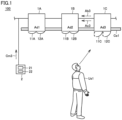
- Fig. 1 is a diagram showing an indoor space of a multi-unit air conditioning system 100 according to Embodiment 1.
- indoor units 1A, 1B, and 1C and a remote controller 2 are disposed in an indoor space (a second space).
- Indoor units 1A to 1C are installed on a ceiling Ce1.
- Indoor units 1A to 1C and an outdoor unit (not shown in Fig. 1 ) disposed on an outdoor space (a first space) form a refrigeration cycle, and indoor units 1A to 1C sends an air to the indoor space.
- indoor units 1A to 1C shown in Fig. 1 are part of multiple indoor units included in multi-unit air conditioning system 100.
- the indoor units may be disposed in multiple spaces.
- vanes Wind-direction adjusting plates
- the indoor unit 1A includes vanes 11A and 12A.
- Indoor unit 1B includes vanes 11B and 12B.
- Indoor unit 1C includes vanes 11C and 12C. The operation of each vane is viewable from the indoor space.
- Remote controller 2 is installed on a wall of the indoor space.
- Remote controller 2 includes a display unit 21 and an operation unit 22.
- a user Us1 can check the room temperature, the operation mode, the air delivery rate of each indoor unit, and the direction in which the indoor unit blows, etc.
- user Us1 can change the room temperature setting, the operation mode, the air delivery rate of each indoor unit, and the direction in which the indoor unit blows, etc. For example, as user Us1 changes on operation unit 22 the direction in which indoor unit 1A blows, the orientations of vanes 11A and 12A are changed.
- user Us1 includes, for example, an operator who performs maintenance of multi-unit air conditioning system 100.
- the outdoor unit, the indoor units, and remote controller 2 included in multi-unit air conditioning system 100 are connected to a communication network and communicable with another other.
- the indoor units are each assigned with a unique address (identification information) that is used for communications with remote controller 2.
- Indoor units 1A, 1B, and 1C are assigned with addresses Ad1, Ad2, and Ad3, respectively.
- each malfunctioning indoor unit transmits a malfunction occurred signal which includes the address of the indoor unit and a malfunction code to remote controller 2.
- Fig. 1 shows a malfunctioning indoor unit 1C transmitting a malfunction occurred signal Ab3, which includes address Ad3 and a malfunction code, to remote controller 2.
- remote controller 2 In response to the receipt of malfunction occurred signal Ab3, remote controller 2 automatically transmits a notification signal Cm3 to address Ad3 included in malfunction occurred signal Ab3.
- indoor unit 1C causes vanes 11C and 12C to swing, and transmits a response signal Ac3 which includes address Ad3 and the operational statuses of vanes 11C and 12C to remote controller 2.
- User Us1 can visually check that vanes 11C and 12C are swinging, thereby distinguishing a malfunctioning indoor unit 1C from normally operating indoor unit 1A whose vanes 11A and 12A are stopped and a normally operating indoor unit 1B whose vanes 11B and 12B are stopped.
- remote controller 2 if remote controller 2 cannot check, by a response signal corresponding to the transmitted notification signal, that the vanes of each malfunctioning indoor unit are swinging, remote controller 2 transmits a notification signal to all the normally operating indoor units. As a result, the vanes of a normally operating indoor unit are swinging while the vanes of a malfunctioning indoor unit are stopped. Thus, user Us1 can identify a malfunctioning indoor unit among the indoor units in the indoor space.
- the case where remote controller 2 cannot check, by a response signal corresponding to the transmitted notification signal, that the vanes of each malfunctioning indoor unit are swinging includes the case where the response signal contains information indicative of failure of the vanes, and the case where remote controller 2 cannot receive a response signal corresponding to the transmitted notification signal.
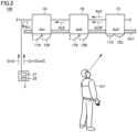
- Fig. 2 is a diagram showing multi-unit air conditioning system 100 of Fig. 1 in which vanes 11C and 12C of indoor unit 1C are failed.
- a malfunctioning indoor unit 1C adds information indicative of the failure of the vanes to response signal Ac3F, and transmits response signal Ac3F to remote controller 2.
- remote controller 2 transmits notification signals Cm1 and Cm2 to normally operating indoor units 1A and 1B, respectively.
- indoor unit 1A transmits response signal Ac1 to remote controller 2, and causes vanes 11A and 12A to swing.
- indoor unit 1B transmits response signal Ac2 to remote controller 2, and causes vanes 11B and 12B to swing.
- User Us1 can visually check that vanes 11C and 12C of malfunctioning indoor unit 1C are stopped, thereby distinguishing malfunctioning indoor unit 1C from a normally operating indoor unit 1A whose vanes 11A and 12A are swinging and indoor unit 1B whose vanes 11B and 12B are swinging.
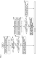
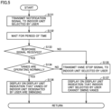
- Fig. 3 is a flowchart showing a flow of a process that is performed by remote controller 2 of Figs. 1 and 2 upon receipt of a malfunction occurred signal from an indoor unit.
- the process illustrated in Fig. 3 is called from the main routine that performs an integrated process for remote controller 2.
- the steps will be referred to simply as S.
- remote controller 2 transmits a notification signal to an indoor unit that corresponds to the address included in the received malfunction occurred signal, and passes the process to S102.
- remote controller 2 waits for a period of time, and then passes the process to S103. Note that if remote controller 2 receives multiple malfunction occurred signals simultaneously, remote controller 2 transmits a notification signal to an indoor unit corresponding to an address in the order starting from the smallest address to the largest address.
- remote controller 2 determines whether remote controller 2 has received a response signal corresponding to the notification signal transmitted in S101. If remote controller 2 has received a response signal (YES in S103), remote controller 2 passes the process to S104. If remote controller 2 does not receive a response signal (NO in S103), remote controller 2 passes the process to S105.
- remote controller 2 determines whether the response signal contains information indicating that the vanes are normally operating. If the response signal contains the information indicating that the vanes are normally operating (YES in S104), remote controller 2, in S106, displays on display unit 21 an indication that the vanes of a malfunctioning indoor unit are swinging, the address of the malfunctioning indoor unit, and a malfunction code, and returns the process to the main routine. If the response signal contains information indicating that the vanes are malfunctioning (NO in S104), remote controller 2 passes the process to S105.
- remote controller 2 transmits a vane stop signal to the malfunctioning indoor unit, and passes the process to S107.
- remote controller 2 transmits a notification signal to all the normally operating indoor units, and passes the process to S108.
- remote controller 2 waits for a period of time, and then passes the process to S109.
- remote controller 2 determines whether the response signals from the normally operating indoor units each include information indicating that the vanes are normally operating. If the response signal from each normally operating indoor unit includes the information indicating that the vanes are normally operating (YES in S109), remote controller 2, in S110, displays on display unit 21 an indication that the vanes of the normally operating indoor units are swinging, the address of a malfunctioning indoor unit, and a malfunction code, and returns the process to the main routine.
- remote controller 2 in S111, displays the address of a normally operating indoor unit whose vanes are stopped and the address of a malfunctioning indoor unit on display unit 21, and returns the process to the main routine.
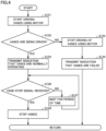
- Fig. 4 is a flowchart showing a flow of a process that is performed by an indoor unit included in multi-unit air conditioning system 100 according to Embodiment 1, upon receipt of a notification signal.
- the process illustrated in Fig. 4 is called from the main routine that performs the integrated process for the indoor unit.
- the indoor unit starts driving the vanes, using a motor, and passes the process to S122.
- the indoor unit determines whether the vanes are being driven.
- the indoor unit may use a signal regarding the rotation of the motor obtained by a sensor to determine in a mechanical or circuitry manner whether the vanes are being driven, or use a video capturing the vanes or the motor obtained by a camera to determine whether the vanes are being driven.
- the indoor unit in S123, stops the motor, and passes the process to S124.
- the indoor unit adds information indicative of failure of the vanes to a response signal, transmits the response signal to remote controller 2, and returns the process to the main routine.
- the indoor unit in S125, adds information indicating that the vanes are normally operating to a response signal, transmits the response signal to remote controller 2, and passes the process to S126.
- the indoor unit determines whether the indoor unit has received a vane stop signal.
- the indoor unit If the indoor unit does not receive a vane stop signal (NO in S126), the indoor unit, in S127, waits for a period of time, and then returns the process to S126. If the indoor unit has received a vane stop signal (YES in S126), the indoor unit, in S128, stops the motor driving the vanes, and returns the process to the main routine.
- remote controller 2 in response to the receipt of the malfunction occurred signal, automatically transmits a notification signal to the indoor unit corresponding to the address included in the malfunction occurred signal. Remote controller 2 also transmits a notification signal to the indoor unit that is selected by user Us1 on operation unit 22 of remote controller 2.
- Fig. 5 is a flowchart showing a flow of a process that is performed by remote controller 2 of Figs. 1 and 2 when the user has selected an indoor unit on operation unit 22.
- the process illustrated in Fig. 5 is called from the main routine that performs the integrated process for remote controller 2.
- remote controller 2 transmits a notification signal to the indoor unit selected by user Us1, and passes the process to S132.
- remote controller 2 waits for a period of time, and then passes the process to S133.
- remote controller 2 determines whether remote controller 2 has received a response signal corresponding to the notification signal transmitted in S131. If remote controller 2 has received a response signal (YES in S133), remote controller 2 passes the process to S134. If remote controller 2 does not receive a response signal (NO in S133), remote controller 2 passes the process to S135.
- remote controller 2 determines whether the response signal contains information indicating that the vanes are operating normally. If the response signal includes the information indicating that the vanes are operating normally (YES in S134), remote controller 2, in S136, displays on display unit 21 an indication that the vanes of the indoor unit selected by the user are swinging, and the address of the indoor unit, and returns the process to the main routine. If the response signal contains information indicating that the vanes are malfunctioning (NO in S134), remote controller 2 passes the process to S135.
- remote controller 2 transmits a vane stop signal to the indoor unit selected by the user, and passes the process to S137.
- remote controller 2 displays on display unit 21 an indication that the indoor unit selected by the user cannot swing the vanes, and the address of the indoor unit, and returns the process to the main routine.
- the notification unit may be any configuration, insofar as the operation of the notification unit can be checked by the user who is in the indoor space.
- the notification unit may include a fan, a light emitting diode (LED), and a loudspeaker. If a fan is used as the notification unit, the user in a room can distinguish between a malfunctioning indoor unit and a normally operating indoor unit, based on an air delivery rate from the fan per unit time. If an LED is used as the notification unit, the user in a room can distinguish between a malfunctioning indoor unit and a normally operating indoor unit, based on a light-emitting mode of the LED. If a loudspeaker is used as the notification unit, the user in a room can distinguish between a malfunctioning indoor unit and a normally operating indoor unit, based on a sound from the loudspeaker or a volume of the loudspeaker.
- Embodiment 2 will be described, with reference to the use of a personal computer, instead of the remote controller according to Embodiment 1.
- Fig. 6 is a diagram showing an indoor space of a multi-unit air conditioning system 200 according to Embodiment 2.
- Multi-unit air conditioning systems 200 and 100 are the same, except that multi-unit air conditioning system 200 includes a personal computer 2B replacing remote controller 2 of Fig. 1 , and each indoor unit includes a wireless communications unit. Thus, the description will not be repeated.
- indoor units 1A, 1B, and 1C include wireless communications units 13A, 13B, and 13C, respectively.
- Indoor units 1A, 1B, and 1C perform wireless communications with personal computer 2B.
- Indoor units 1A, 1B, and 1C and personal computer 2B may communicate with each other via wired connection.
- Personal computer 2B includes a display 21B (display unit) and an operation unit 22B.
- Operation unit 22B has a keyboard and a touchpad.
- An application for controlling multi-unit air conditioning system 200 is pre-installed in personal computer 2B.
- a user Us1 manipulates the application through input to operation unit 22B on personal computer 2B, thereby controlling multi-unit air conditioning system 200.
- Personal computer 2B performs the processes illustrated in Figs. 3 and 5 . While personal computer 2B is disposed in an indoor space in Fig. 6 , it should be noted that personal computer 2B may be disposed in an outdoor space.
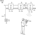
- FIG. 7 is a diagram showing a multi-unit air conditioning system 300 according to Embodiment 3.
- Multi-unit air conditioning systems 300 and 100 are the same, except that multi-unit air conditioning systems 300 includes a control device 2C replacing remote controller 2 of Fig. 1 . Thus, the description will not be repeated.
- Control device 2C is installed in an outdoor unit 3.
- Control device 2C includes a display 21C (display unit) and an operation unit 22C. Control device 2C performs the processes illustrated in Figs. 3 and 5 .
- a user Us2 in the outdoor space selects an indoor unit via operation unit 22C, thereby allowing a user Us1 in the indoor space to check that vanes 11C and 12C of the indoor unit are swinging.
- Fig. 7 shows user Us2 selecting an indoor unit 1C.
- Embodiment 4 a configuration will be described which further facilitates the discovery of a malfunctioning indoor unit than Embodiment 1 by a malfunctioning indoor unit and a normally operating indoor unit each having a different wireless communication strength, in addition to each having a different notification unit operation.
- Fig. 8 is a diagram showing an indoor space of a multi-unit air conditioning system 400 according to Embodiment 4.
- Multi-unit air conditioning systems 400 and 100 are the same, except that multi-unit air conditioning systems 400 includes remote controller 2D replacing remote controller 2, and indoor units each including a wireless communication unit, and a user Us1 is holding a mobile terminal 4. Thus, the description will not be repeated.
- indoor units 1A, 1B, and 1C include wireless communications units 14A, 14B, and 14C, respectively.
- remote controller 2D transmits a notification signal
- remote controller 2D transmits a wireless strength signal to each indoor unit in accordance with the status of the indoor unit so that the strength of a wireless radio (wireless strength) of a malfunctioning indoor unit and the wireless strength of a normally operating indoor unit are different.
- the wireless communications unit of each of the multiple indoor units changes the strength for wireless communications.
- remote controller 2D transmits to indoor unit 1C a wireless strength signal corresponding to a maximum wireless strength, and transmits to indoor units 1A and 1B wireless strength signals corresponding to respective minimum wireless strengths.
- Remote controller 2D may transmits to indoor unit 1C a wireless strength signal corresponding to a minimum wireless strength of indoor unit 1C, and transmits to indoor units 1A and 1B wireless strength signals corresponding to maximum wireless strengths of indoor units 1A and 1B, respectively.
- a notification signal and a wireless strength signal may be separate signals, or a wireless strength may be added to a notification signal.
- Mobile terminal 4 is, for example, smartphone.
- Mobile terminal 4 includes a display 41 and an operation unit 42.
- Operation unit 42 has buttons and a touch panel.
- Mobile terminal 4 displays on the display 41 the strength of a wireless radio emitted from a device that is capable of wireless communications.
- User Us1 can check whether a malfunctioning indoor unit is in proximity, while checking the wireless strength displayed on the display 41 of mobile terminal 4.
- the discovery of a malfunctioning indoor unit can be further facilitated than Embodiment 1 by allowing the user to check the wireless communication strength.
Landscapes
- Engineering & Computer Science (AREA)
- Chemical & Material Sciences (AREA)
- Combustion & Propulsion (AREA)
- Mechanical Engineering (AREA)
- General Engineering & Computer Science (AREA)
- Human Computer Interaction (AREA)
- Physics & Mathematics (AREA)
- General Physics & Mathematics (AREA)
- Automation & Control Theory (AREA)
- Health & Medical Sciences (AREA)
- Biomedical Technology (AREA)
- Air Conditioning Control Device (AREA)
Claims (9)
- Système (100, 200, 300, 400) de climatisation à unités multiples, comportant :une unité (3) d'extérieur disposée dans un premier espace ;une pluralité d'unités (1A, 1B, 1C) d'intérieur configurées pour envoyer de l'air à au moins un second espace différent du premier espace, la pluralité d'unités (1A, 1B, 1C) d'intérieur et l'unité (3) d'extérieur formant un cycle frigorifique ; etun dispositif (2, 2B, 2C, 2D) de commande configuré pour commander la pluralité d'unités (1A, 1B, 1C) d'intérieur,chaque unité d'intérieur parmi la pluralité d'unités (1A, 1B, 1C) d'intérieur comprenant une unité (11A, 11B, 11C, 12A, 12B, 12C) de notification,chaque unité d'intérieur étant configurée pour faire fonctionner l'unité (11A, 11B, 11C, 12A, 12B, 12C) de notification de l'unité d'intérieur en réponse à un signal (Cm1, Cm2, Cm3) de notification provenant du dispositif (2, 2B, 2C, 2D) de commande, et pour transmettre au dispositif (2, 2B, 2C, 2D) de commande un signal (Ac1, Ac2, Ac3, Ac3F) de réponse qui comprend des informations d'identification de l'unité d'intérieur, et un état opérationnel de l'unité (11A, 11B, 11C, 12A, 12B, 12C) de notification de l'unité d'intérieur,le système (100, 200, 300, 400) de climatisation à unités multiples étant configuré de telle façon qu'un fonctionnement de l'unité (11A, 11B, 11C, 12A, 12B, 12C) de notification puisse être vérifié par un utilisateur (Us1) qui se trouve dans le ou les seconds espaces,les unités (1A, 1B, 1C) d'intérieur étant configurées de telle façon que, lorsqu'au moins une unité d'intérieur comprise dans la pluralité d'unités (1A, 1B, 1C) d'intérieur dysfonctionne, l'unité ou chacune des unités d'intérieur transmettent au dispositif (2, 2B, 2C, 2D) de commande un signal (Ab3) de survenance de dysfonctionnement qui comprend des informations d'identification de l'unité d'intérieur,caractérisé en ce que le dispositif (2, 2B, 2C, 2D) de commande est configuré, lorsque le dispositif (2, 2B, 2C, 2D) de commande ne peut pas vérifier le fonctionnement de l'unité (11A, 11B, 11C, 12A, 12B, 12C) de notification comprise dans l'unité ou chacune des unités d'intérieur par un signal (Ac1, Ac2, Ac3, Ac3F) de réponse correspondant au signal (Cm1, Cm2, Cm3) de notification transmis, pour transmettre un signal (Cm1, Cm2, Cm3) de notification à une unité d'intérieur à laquelle un signal (Cm1, Cm2, Cm3) de notification n'a pas été transmis parmi la pluralité d'unités (1A, 1B, 1C) d'intérieur.
- Système (100, 200, 300, 400) de climatisation à unités multiples selon la revendication 1,
le dispositif (2, 2B, 2C, 2D) de commande étant disposé dans le second ou l'un quelconque des seconds espaces, et étant configuré, en réponse à la réception d'un signal (Ab3) de survenance de dysfonctionnement, pour transmettre automatiquement un signal (Cm1, Cm2, Cm3) de notification à une unité d'intérieur correspondant à des informations d'identification comprises dans le signal (Ab3) de survenance de dysfonctionnement. - Système (100, 200, 300, 400) de climatisation à unités multiples selon la revendication 1 ou 2,
le dispositif (2, 2B, 2C, 2D) de commandecomprenant une unité (22, 22B, 22C, 42) d'exploitation qui est configurée pour permettre à l'utilisateur (Us1) de sélectionner une unité d'intérieur parmi la pluralité d'unités (1A, 1B, 1C) d'intérieur, etétant configuré pour transmettre un signal (Cm1, Cm2, Cm3) de notification à l'unité d'intérieur sélectionnée par l'utilisateur (Us1) sur l'unité (22, 22B, 22C, 42) d'exploitation. - Système (100, 200, 300, 400) de climatisation à unités multiples selon l'une quelconque des revendications 1 à 3,le dispositif (2, 2B, 2C, 2D) de commande comprenant une unité (21, 21B, 21C, 41) d'affichage, etle dispositif (2, 2B, 2C, 2D) de commande étant configuré pour indiquer sur l'unité (21, 21B, 21C, 41) d'affichage si chaque unité (11A, 11B, 11C, 12A, 12B, 12C) de notification comprise dans l'unité ou les unités d'intérieur fonctionne ou si l'unité (11A, 11B, 11C, 12A, 12B, 12C) de notification d'une unité d'intérieur fonctionnant normalement parmi la pluralité d'unités (1A, 1B, 1C) d'intérieur fonctionne.
- Système (300) de climatisation à unités multiples selon la revendication 3 ou 4,
le dispositif (2C) de commande étant disposé dans le premier espace. - Système (200) de climatisation à unités multiples selon l'une quelconque des revendications 1 à 5,
le dispositif (2B) de commande étant un ordinateur personnel dans lequel une application servant à commander la pluralité d'unités (1A, 1B, 1C) d'intérieur est installée, et étant configuré pour transmettre un signal (Cm1, Cm2, Cm3) de notification à une unité d'intérieur sélectionnée parmi la pluralité d'unités (1A, 1B, 1C) d'intérieur par une entrée de l'utilisateur (Us1) vers l'application. - Système (400) de climatisation à unités multiples selon l'une quelconque des revendications 1 à 6,chacune de la pluralité d'unités (1A, 1B, 1C) d'intérieur comprenant en outre une unité (14A, 14B, 14C) de communications sans fil,le dispositif (2, 2B, 2C, 2D) de commande étant configuré, lorsque le dispositif (2, 2B, 2C, 2D) de commande émet le signal (Cm1, Cm2, Cm3) de notification, pour transmettre à chaque unité d'intérieur parmi la pluralité d'unités (1A, 1B, 1C) d'intérieur un signal d'intensité sans fil en réaction à un état de l'unité d'intérieur de telle sorte qu'une unité d'intérieur qui dysfonctionne et une unité d'intérieur fonctionnant normalement présentent des intensités sans fil différentes, etl'unité (14A, 14B, 14C) de communications sans fil étant configurée pour modifier une intensité pour les communications sans fil en réponse au signal d'intensité sans fil provenant du dispositif (2D) de commande.
- Système (100, 200, 300, 400) de climatisation à unités multiples selon l'une quelconque des revendications 1 à 7,
en tant qu'unité de notification, chaque unité de la pluralité d'unités (1A, 1B, 1C) d'intérieur comprenant une plaque (11A, 11B, 11C, 12A, 12B, 12C) de réglage de direction du souffle qui est configurée pour modifier une direction dans laquelle l'unité d'intérieur souffle, et étant configurée pour faire osciller la plaque (11A, 11B, 11C, 12A, 12B, 12C) de réglage de direction du souffle en réponse au signal (Cm1, Cm2, Cm3) de notification provenant du dispositif (2, 2B, 2C, 2D) de commande. - Procédé de climatisation à unités multiples réalisé par un système (100, 200, 300, 400) de climatisation à unités multiples,le système (100, 200, 300, 400) de climatisation à unités multiples comportant :une unité (3) d'extérieur disposé danse un premier espace ;une pluralité d'unités (1A, 1B, 1C) d'intérieur destinées à envoyer de l'air à au moins un second espace différent du premier espace, la pluralité d'unités (1A, 1B, 1C) d'intérieur et l'unité (3) d'extérieur formant un cycle frigorifique ; etun dispositif (2, 2B, 2C, 2D) de commande destiné à commander la pluralité d'unités (1A, 1B, 1C) d'intérieur,chaque unité d'intérieur parmi la pluralité d'unités (1A, 1B, 1C) d'intérieur comprenant une unité (11A, 11B, 11C, 12A, 12B, 12C) de notification, et faisant fonctionner l'unité (11A, 11B, 11C, 12A, 12B, 12C) de notification de l'unité d'intérieur en réponse à un signal (Cm1, Cm2, Cm3) de notification provenant du dispositif (2, 2B, 2C, 2D) de commande, et transmettant au dispositif (2, 2B, 2C, 2D) de commande un signal (Ac1, Ac2, Ac3, Ac3F) de réponse qui comprend des informations d'identification de l'unité d'intérieur, et un état opérationnel de l'unité (11A, 11B, 11C, 12A, 12B, 12C) de notification de l'unité d'intérieur,un fonctionnement de l'unité (11A, 11B, 11C, 12A, 12B, 12C) de notification pouvant être vérifié par un utilisateur (Us1) qui se trouve dans le ou les seconds espaces,lorsqu'au moins une unité d'intérieur comprise dans la pluralité d'unités (1A, 1B, 1C) d'intérieur dysfonctionne, l'unité ou chacune des unités d'intérieur transmettant au dispositif (2, 2B, 2C, 2D) de commande un signal (Ab3) de survenance de dysfonctionnement qui comprend des informations d'identification de l'unité d'intérieur, caractérisé en ce quelorsque le dispositif (2, 2B, 2C, 2D) de commande ne peut pas vérifier le fonctionnement de l'unité (11A, 11B, 11C, 12A, 12B, 12C) de notification comprise dans l'unité ou chacune des unités d'intérieur par un signal (Ac1, Ac2, Ac3, Ac3F) de réponse correspondant au signal (Cm1, Cm2, Cm3) de notification transmis, le dispositif (2, 2B, 2C, 2D) de commande transmet un signal (Cm1, Cm2, Cm3) de notification à une unité d'intérieur à laquelle un signal (Cm1, Cm2, Cm3) de notification n'a pas été transmis parmi la pluralité d'unités (1A, 1B, 1C) d'intérieur.
Applications Claiming Priority (1)
| Application Number | Priority Date | Filing Date | Title |
|---|---|---|---|
| PCT/JP2019/003398 WO2020157920A1 (fr) | 2019-01-31 | 2019-01-31 | Système de climatisation à plusieurs unités |
Publications (3)
| Publication Number | Publication Date |
|---|---|
| EP3919829A1 EP3919829A1 (fr) | 2021-12-08 |
| EP3919829A4 EP3919829A4 (fr) | 2022-02-09 |
| EP3919829B1 true EP3919829B1 (fr) | 2023-05-24 |
Family
ID=71842014
Family Applications (1)
| Application Number | Title | Priority Date | Filing Date |
|---|---|---|---|
| EP19914001.3A Active EP3919829B1 (fr) | 2019-01-31 | 2019-01-31 | Système de climatisation à plusieurs unités |
Country Status (4)
| Country | Link |
|---|---|
| US (1) | US11788749B2 (fr) |
| EP (1) | EP3919829B1 (fr) |
| JP (1) | JP7077427B2 (fr) |
| WO (1) | WO2020157920A1 (fr) |
Families Citing this family (1)
| Publication number | Priority date | Publication date | Assignee | Title |
|---|---|---|---|---|
| CN111720984B (zh) * | 2019-03-19 | 2022-04-01 | 青岛海尔空调电子有限公司 | 空调系统及数据传输的方法、装置及计算机存储介质 |
Family Cites Families (18)
| Publication number | Priority date | Publication date | Assignee | Title |
|---|---|---|---|---|
| JP3556992B2 (ja) * | 1995-03-22 | 2004-08-25 | 三菱電機ビルテクノサービス株式会社 | マルチエアコン異常停止時の異常報知器 |
| JP4023488B2 (ja) * | 1995-11-17 | 2007-12-19 | 三菱電機株式会社 | 空調機 |
| JPH10318589A (ja) * | 1997-05-16 | 1998-12-04 | Daikin Ind Ltd | 空気調和装置 |
| JP2000193292A (ja) | 1998-12-25 | 2000-07-14 | Sanyo Electric Co Ltd | 空気調和機 |
| JP2001165490A (ja) * | 1999-12-08 | 2001-06-22 | Matsushita Electric Ind Co Ltd | マルチ空気調和機 |
| JP2002089944A (ja) * | 2000-09-11 | 2002-03-27 | Mitsubishi Heavy Ind Ltd | 空気調和機運転装置、空気調和機制御装置及び空気調和機リモートコントローラ |
| JP2003074968A (ja) * | 2001-08-28 | 2003-03-12 | Noritz Corp | 給湯システム |
| JP4006311B2 (ja) * | 2002-10-07 | 2007-11-14 | 大阪瓦斯株式会社 | 故障検知機能を有する報知装置 |
| US7308384B2 (en) * | 2004-01-20 | 2007-12-11 | Carrier Corporation | Ordered record of system-wide fault in an HVAC system |
| JP4325592B2 (ja) | 2005-06-24 | 2009-09-02 | ダイキン工業株式会社 | 設備機器対応付け支援システムおよび無線情報端末 |
| KR101450540B1 (ko) * | 2007-10-30 | 2014-10-15 | 엘지전자 주식회사 | 공기조화기의 에러관리 시스템 |
| JP5097612B2 (ja) * | 2008-05-08 | 2012-12-12 | 三菱電機ビルテクノサービス株式会社 | 空気調和機及び空気調和システム |
| JP2011052945A (ja) * | 2009-09-04 | 2011-03-17 | Sharp Corp | 機器 |
| JP2011158168A (ja) * | 2010-02-01 | 2011-08-18 | Panasonic Corp | 空気調和機 |
| KR101654060B1 (ko) * | 2010-03-08 | 2016-09-05 | 엘지전자 주식회사 | 공기조화시스템 및 제어방법 |
| JP5804973B2 (ja) | 2012-02-24 | 2015-11-04 | 三菱電機株式会社 | 空気調和機 |
| US9829230B2 (en) * | 2013-02-28 | 2017-11-28 | Mitsubishi Electric Corporation | Air conditioning apparatus |
| KR101707617B1 (ko) * | 2015-09-30 | 2017-02-21 | 삼성전자주식회사 | 공기 조화기 및 그 제어 방법 |
-
2019
- 2019-01-31 EP EP19914001.3A patent/EP3919829B1/fr active Active
- 2019-01-31 JP JP2020569281A patent/JP7077427B2/ja not_active Expired - Fee Related
- 2019-01-31 US US17/289,052 patent/US11788749B2/en active Active
- 2019-01-31 WO PCT/JP2019/003398 patent/WO2020157920A1/fr not_active Ceased
Also Published As
| Publication number | Publication date |
|---|---|
| JP7077427B2 (ja) | 2022-05-30 |
| EP3919829A1 (fr) | 2021-12-08 |
| US20210404684A1 (en) | 2021-12-30 |
| US11788749B2 (en) | 2023-10-17 |
| JPWO2020157920A1 (ja) | 2021-09-30 |
| WO2020157920A1 (fr) | 2020-08-06 |
| EP3919829A4 (fr) | 2022-02-09 |
Similar Documents
| Publication | Publication Date | Title |
|---|---|---|
| US7775452B2 (en) | Serial communicating HVAC system | |
| WO2008035402A1 (fr) | SystÈme de climatisation de l'air | |
| EP2083227A1 (fr) | Système de réglage pour climatiseur | |
| KR20170107316A (ko) | 공기조화기 시스템 | |
| WO2018154652A1 (fr) | Dispositif de télécommande, appareil de conditionnement d'air et système de conditionnement d'air | |
| EP3919829B1 (fr) | Système de climatisation à plusieurs unités | |
| JP7016023B2 (ja) | 機器情報管理システム、リモコンおよび空気調和装置 | |
| CN109405193B (zh) | 空调系统及其遥控器配对方法 | |
| AU2019300633B2 (en) | Ventilation system | |
| EP3139543B1 (fr) | Allocation d'adresses dans un système de climatisation | |
| KR101860920B1 (ko) | 공기조화기 및 그 제어방법 | |
| US11913661B2 (en) | Air-conditioning system | |
| KR20190038056A (ko) | 공기조화기 시스템 및 그 제어 방법 | |
| KR20140100651A (ko) | 공기조화기 및 그 동작방법 | |
| CN106662357B (zh) | 空调系统 | |
| CN107024920A (zh) | 一种故障诊断的方法、装置及空调系统 | |
| KR20130035022A (ko) | 공기조화기 및 그 제어방법 | |
| KR102550355B1 (ko) | 빌딩제어 시스템 및 그 제어방법 | |
| KR20080038899A (ko) | 시스템 에어컨의 통신에러 진단장치 및 그 방법 | |
| JP2012127603A (ja) | 空調システム | |
| JP2018112380A (ja) | 空調管理装置およびその表示制御方法 | |
| KR102000071B1 (ko) | 공기조화기 시스템 및 그 제어 방법 | |
| KR20100032201A (ko) | 공기조화기 및 그 동작방법 | |
| KR101966950B1 (ko) | 멀티형 공기 조화기 및 그의 제어방법 | |
| JP7329759B2 (ja) | 機器情報管理システム |
Legal Events
| Date | Code | Title | Description |
|---|---|---|---|
| STAA | Information on the status of an ep patent application or granted ep patent |
Free format text: STATUS: THE INTERNATIONAL PUBLICATION HAS BEEN MADE |
|
| PUAI | Public reference made under article 153(3) epc to a published international application that has entered the european phase |
Free format text: ORIGINAL CODE: 0009012 |
|
| STAA | Information on the status of an ep patent application or granted ep patent |
Free format text: STATUS: REQUEST FOR EXAMINATION WAS MADE |
|
| 17P | Request for examination filed |
Effective date: 20210518 |
|
| AK | Designated contracting states |
Kind code of ref document: A1 Designated state(s): AL AT BE BG CH CY CZ DE DK EE ES FI FR GB GR HR HU IE IS IT LI LT LU LV MC MK MT NL NO PL PT RO RS SE SI SK SM TR |
|
| A4 | Supplementary search report drawn up and despatched |
Effective date: 20220111 |
|
| RIC1 | Information provided on ipc code assigned before grant |
Ipc: F24F 11/79 20180101ALI20220104BHEP Ipc: F24F 11/52 20180101ALI20220104BHEP Ipc: F24F 11/38 20180101ALI20220104BHEP Ipc: F24F 11/32 20180101AFI20220104BHEP |
|
| DAV | Request for validation of the european patent (deleted) | ||
| DAX | Request for extension of the european patent (deleted) | ||
| GRAP | Despatch of communication of intention to grant a patent |
Free format text: ORIGINAL CODE: EPIDOSNIGR1 |
|
| STAA | Information on the status of an ep patent application or granted ep patent |
Free format text: STATUS: GRANT OF PATENT IS INTENDED |
|
| INTG | Intention to grant announced |
Effective date: 20221209 |
|
| GRAS | Grant fee paid |
Free format text: ORIGINAL CODE: EPIDOSNIGR3 |
|
| GRAA | (expected) grant |
Free format text: ORIGINAL CODE: 0009210 |
|
| STAA | Information on the status of an ep patent application or granted ep patent |
Free format text: STATUS: THE PATENT HAS BEEN GRANTED |
|
| AK | Designated contracting states |
Kind code of ref document: B1 Designated state(s): AL AT BE BG CH CY CZ DE DK EE ES FI FR GB GR HR HU IE IS IT LI LT LU LV MC MK MT NL NO PL PT RO RS SE SI SK SM TR |
|
| REG | Reference to a national code |
Ref country code: GB Ref legal event code: FG4D |
|
| REG | Reference to a national code |
Ref country code: CH Ref legal event code: EP |
|
| REG | Reference to a national code |
Ref country code: DE Ref legal event code: R096 Ref document number: 602019029406 Country of ref document: DE |
|
| REG | Reference to a national code |
Ref country code: AT Ref legal event code: REF Ref document number: 1569718 Country of ref document: AT Kind code of ref document: T Effective date: 20230615 |
|
| REG | Reference to a national code |
Ref country code: IE Ref legal event code: FG4D |
|
| REG | Reference to a national code |
Ref country code: LT Ref legal event code: MG9D |
|
| REG | Reference to a national code |
Ref country code: NL Ref legal event code: MP Effective date: 20230524 |
|
| REG | Reference to a national code |
Ref country code: AT Ref legal event code: MK05 Ref document number: 1569718 Country of ref document: AT Kind code of ref document: T Effective date: 20230524 |
|
| PG25 | Lapsed in a contracting state [announced via postgrant information from national office to epo] |
Ref country code: SE Free format text: LAPSE BECAUSE OF FAILURE TO SUBMIT A TRANSLATION OF THE DESCRIPTION OR TO PAY THE FEE WITHIN THE PRESCRIBED TIME-LIMIT Effective date: 20230524 Ref country code: PT Free format text: LAPSE BECAUSE OF FAILURE TO SUBMIT A TRANSLATION OF THE DESCRIPTION OR TO PAY THE FEE WITHIN THE PRESCRIBED TIME-LIMIT Effective date: 20230925 Ref country code: NO Free format text: LAPSE BECAUSE OF FAILURE TO SUBMIT A TRANSLATION OF THE DESCRIPTION OR TO PAY THE FEE WITHIN THE PRESCRIBED TIME-LIMIT Effective date: 20230824 Ref country code: NL Free format text: LAPSE BECAUSE OF FAILURE TO SUBMIT A TRANSLATION OF THE DESCRIPTION OR TO PAY THE FEE WITHIN THE PRESCRIBED TIME-LIMIT Effective date: 20230524 Ref country code: ES Free format text: LAPSE BECAUSE OF FAILURE TO SUBMIT A TRANSLATION OF THE DESCRIPTION OR TO PAY THE FEE WITHIN THE PRESCRIBED TIME-LIMIT Effective date: 20230524 Ref country code: AT Free format text: LAPSE BECAUSE OF FAILURE TO SUBMIT A TRANSLATION OF THE DESCRIPTION OR TO PAY THE FEE WITHIN THE PRESCRIBED TIME-LIMIT Effective date: 20230524 |
|
| PG25 | Lapsed in a contracting state [announced via postgrant information from national office to epo] |
Ref country code: RS Free format text: LAPSE BECAUSE OF FAILURE TO SUBMIT A TRANSLATION OF THE DESCRIPTION OR TO PAY THE FEE WITHIN THE PRESCRIBED TIME-LIMIT Effective date: 20230524 Ref country code: PL Free format text: LAPSE BECAUSE OF FAILURE TO SUBMIT A TRANSLATION OF THE DESCRIPTION OR TO PAY THE FEE WITHIN THE PRESCRIBED TIME-LIMIT Effective date: 20230524 Ref country code: LV Free format text: LAPSE BECAUSE OF FAILURE TO SUBMIT A TRANSLATION OF THE DESCRIPTION OR TO PAY THE FEE WITHIN THE PRESCRIBED TIME-LIMIT Effective date: 20230524 Ref country code: LT Free format text: LAPSE BECAUSE OF FAILURE TO SUBMIT A TRANSLATION OF THE DESCRIPTION OR TO PAY THE FEE WITHIN THE PRESCRIBED TIME-LIMIT Effective date: 20230524 Ref country code: IS Free format text: LAPSE BECAUSE OF FAILURE TO SUBMIT A TRANSLATION OF THE DESCRIPTION OR TO PAY THE FEE WITHIN THE PRESCRIBED TIME-LIMIT Effective date: 20230924 Ref country code: HR Free format text: LAPSE BECAUSE OF FAILURE TO SUBMIT A TRANSLATION OF THE DESCRIPTION OR TO PAY THE FEE WITHIN THE PRESCRIBED TIME-LIMIT Effective date: 20230524 Ref country code: GR Free format text: LAPSE BECAUSE OF FAILURE TO SUBMIT A TRANSLATION OF THE DESCRIPTION OR TO PAY THE FEE WITHIN THE PRESCRIBED TIME-LIMIT Effective date: 20230825 |
|
| PG25 | Lapsed in a contracting state [announced via postgrant information from national office to epo] |
Ref country code: FI Free format text: LAPSE BECAUSE OF FAILURE TO SUBMIT A TRANSLATION OF THE DESCRIPTION OR TO PAY THE FEE WITHIN THE PRESCRIBED TIME-LIMIT Effective date: 20230524 |
|
| PG25 | Lapsed in a contracting state [announced via postgrant information from national office to epo] |
Ref country code: SK Free format text: LAPSE BECAUSE OF FAILURE TO SUBMIT A TRANSLATION OF THE DESCRIPTION OR TO PAY THE FEE WITHIN THE PRESCRIBED TIME-LIMIT Effective date: 20230524 |
|
| PGFP | Annual fee paid to national office [announced via postgrant information from national office to epo] |
Ref country code: GB Payment date: 20231207 Year of fee payment: 6 |
|
| PG25 | Lapsed in a contracting state [announced via postgrant information from national office to epo] |
Ref country code: SM Free format text: LAPSE BECAUSE OF FAILURE TO SUBMIT A TRANSLATION OF THE DESCRIPTION OR TO PAY THE FEE WITHIN THE PRESCRIBED TIME-LIMIT Effective date: 20230524 Ref country code: SK Free format text: LAPSE BECAUSE OF FAILURE TO SUBMIT A TRANSLATION OF THE DESCRIPTION OR TO PAY THE FEE WITHIN THE PRESCRIBED TIME-LIMIT Effective date: 20230524 Ref country code: RO Free format text: LAPSE BECAUSE OF FAILURE TO SUBMIT A TRANSLATION OF THE DESCRIPTION OR TO PAY THE FEE WITHIN THE PRESCRIBED TIME-LIMIT Effective date: 20230524 Ref country code: EE Free format text: LAPSE BECAUSE OF FAILURE TO SUBMIT A TRANSLATION OF THE DESCRIPTION OR TO PAY THE FEE WITHIN THE PRESCRIBED TIME-LIMIT Effective date: 20230524 Ref country code: DK Free format text: LAPSE BECAUSE OF FAILURE TO SUBMIT A TRANSLATION OF THE DESCRIPTION OR TO PAY THE FEE WITHIN THE PRESCRIBED TIME-LIMIT Effective date: 20230524 Ref country code: CZ Free format text: LAPSE BECAUSE OF FAILURE TO SUBMIT A TRANSLATION OF THE DESCRIPTION OR TO PAY THE FEE WITHIN THE PRESCRIBED TIME-LIMIT Effective date: 20230524 |
|
| REG | Reference to a national code |
Ref country code: DE Ref legal event code: R097 Ref document number: 602019029406 Country of ref document: DE |
|
| PLBE | No opposition filed within time limit |
Free format text: ORIGINAL CODE: 0009261 |
|
| STAA | Information on the status of an ep patent application or granted ep patent |
Free format text: STATUS: NO OPPOSITION FILED WITHIN TIME LIMIT |
|
| PGFP | Annual fee paid to national office [announced via postgrant information from national office to epo] |
Ref country code: DE Payment date: 20231205 Year of fee payment: 6 |
|
| 26N | No opposition filed |
Effective date: 20240227 |
|
| PG25 | Lapsed in a contracting state [announced via postgrant information from national office to epo] |
Ref country code: SI Free format text: LAPSE BECAUSE OF FAILURE TO SUBMIT A TRANSLATION OF THE DESCRIPTION OR TO PAY THE FEE WITHIN THE PRESCRIBED TIME-LIMIT Effective date: 20230524 |
|
| PG25 | Lapsed in a contracting state [announced via postgrant information from national office to epo] |
Ref country code: SI Free format text: LAPSE BECAUSE OF FAILURE TO SUBMIT A TRANSLATION OF THE DESCRIPTION OR TO PAY THE FEE WITHIN THE PRESCRIBED TIME-LIMIT Effective date: 20230524 Ref country code: IT Free format text: LAPSE BECAUSE OF FAILURE TO SUBMIT A TRANSLATION OF THE DESCRIPTION OR TO PAY THE FEE WITHIN THE PRESCRIBED TIME-LIMIT Effective date: 20230524 |
|
| PG25 | Lapsed in a contracting state [announced via postgrant information from national office to epo] |
Ref country code: MC Free format text: LAPSE BECAUSE OF FAILURE TO SUBMIT A TRANSLATION OF THE DESCRIPTION OR TO PAY THE FEE WITHIN THE PRESCRIBED TIME-LIMIT Effective date: 20230524 |
|
| PG25 | Lapsed in a contracting state [announced via postgrant information from national office to epo] |
Ref country code: MC Free format text: LAPSE BECAUSE OF FAILURE TO SUBMIT A TRANSLATION OF THE DESCRIPTION OR TO PAY THE FEE WITHIN THE PRESCRIBED TIME-LIMIT Effective date: 20230524 |
|
| REG | Reference to a national code |
Ref country code: CH Ref legal event code: PL |
|
| PG25 | Lapsed in a contracting state [announced via postgrant information from national office to epo] |
Ref country code: LU Free format text: LAPSE BECAUSE OF NON-PAYMENT OF DUE FEES Effective date: 20240131 |
|
| PG25 | Lapsed in a contracting state [announced via postgrant information from national office to epo] |
Ref country code: LU Free format text: LAPSE BECAUSE OF NON-PAYMENT OF DUE FEES Effective date: 20240131 |
|
| PG25 | Lapsed in a contracting state [announced via postgrant information from national office to epo] |
Ref country code: BE Free format text: LAPSE BECAUSE OF NON-PAYMENT OF DUE FEES Effective date: 20240131 |
|
| PG25 | Lapsed in a contracting state [announced via postgrant information from national office to epo] |
Ref country code: FR Free format text: LAPSE BECAUSE OF NON-PAYMENT OF DUE FEES Effective date: 20240131 |
|
| PG25 | Lapsed in a contracting state [announced via postgrant information from national office to epo] |
Ref country code: CH Free format text: LAPSE BECAUSE OF NON-PAYMENT OF DUE FEES Effective date: 20240131 |
|
| PG25 | Lapsed in a contracting state [announced via postgrant information from national office to epo] |
Ref country code: FR Free format text: LAPSE BECAUSE OF NON-PAYMENT OF DUE FEES Effective date: 20240131 Ref country code: CH Free format text: LAPSE BECAUSE OF NON-PAYMENT OF DUE FEES Effective date: 20240131 Ref country code: BE Free format text: LAPSE BECAUSE OF NON-PAYMENT OF DUE FEES Effective date: 20240131 |
|
| REG | Reference to a national code |
Ref country code: BE Ref legal event code: MM Effective date: 20240131 |
|
| PG25 | Lapsed in a contracting state [announced via postgrant information from national office to epo] |
Ref country code: BG Free format text: LAPSE BECAUSE OF FAILURE TO SUBMIT A TRANSLATION OF THE DESCRIPTION OR TO PAY THE FEE WITHIN THE PRESCRIBED TIME-LIMIT Effective date: 20230524 |
|
| PG25 | Lapsed in a contracting state [announced via postgrant information from national office to epo] |
Ref country code: BG Free format text: LAPSE BECAUSE OF FAILURE TO SUBMIT A TRANSLATION OF THE DESCRIPTION OR TO PAY THE FEE WITHIN THE PRESCRIBED TIME-LIMIT Effective date: 20230524 |
|
| PG25 | Lapsed in a contracting state [announced via postgrant information from national office to epo] |
Ref country code: IE Free format text: LAPSE BECAUSE OF NON-PAYMENT OF DUE FEES Effective date: 20240131 |
|
| PG25 | Lapsed in a contracting state [announced via postgrant information from national office to epo] |
Ref country code: IE Free format text: LAPSE BECAUSE OF NON-PAYMENT OF DUE FEES Effective date: 20240131 |
|
| REG | Reference to a national code |
Ref country code: DE Ref legal event code: R119 Ref document number: 602019029406 Country of ref document: DE |
|
| PG25 | Lapsed in a contracting state [announced via postgrant information from national office to epo] |
Ref country code: CY Free format text: LAPSE BECAUSE OF FAILURE TO SUBMIT A TRANSLATION OF THE DESCRIPTION OR TO PAY THE FEE WITHIN THE PRESCRIBED TIME-LIMIT; INVALID AB INITIO Effective date: 20190131 |
|
| PG25 | Lapsed in a contracting state [announced via postgrant information from national office to epo] |
Ref country code: HU Free format text: LAPSE BECAUSE OF FAILURE TO SUBMIT A TRANSLATION OF THE DESCRIPTION OR TO PAY THE FEE WITHIN THE PRESCRIBED TIME-LIMIT; INVALID AB INITIO Effective date: 20190131 |
|
| GBPC | Gb: european patent ceased through non-payment of renewal fee |
Effective date: 20250131 |
|
| PG25 | Lapsed in a contracting state [announced via postgrant information from national office to epo] |
Ref country code: DE Free format text: LAPSE BECAUSE OF NON-PAYMENT OF DUE FEES Effective date: 20250801 |
|
| PG25 | Lapsed in a contracting state [announced via postgrant information from national office to epo] |
Ref country code: GB Free format text: LAPSE BECAUSE OF NON-PAYMENT OF DUE FEES Effective date: 20250131 |
|
| PG25 | Lapsed in a contracting state [announced via postgrant information from national office to epo] |
Ref country code: TR Free format text: LAPSE BECAUSE OF FAILURE TO SUBMIT A TRANSLATION OF THE DESCRIPTION OR TO PAY THE FEE WITHIN THE PRESCRIBED TIME-LIMIT Effective date: 20230524 |