EP3919356A1 - Drehwinkeldetektionsvorrichtung, elektrische servolenkvorrichtung und steuerungsverfahren für elektrische servolenkvorrichtung - Google Patents
Drehwinkeldetektionsvorrichtung, elektrische servolenkvorrichtung und steuerungsverfahren für elektrische servolenkvorrichtung Download PDFInfo
- Publication number
- EP3919356A1 EP3919356A1 EP21751494.2A EP21751494A EP3919356A1 EP 3919356 A1 EP3919356 A1 EP 3919356A1 EP 21751494 A EP21751494 A EP 21751494A EP 3919356 A1 EP3919356 A1 EP 3919356A1
- Authority
- EP
- European Patent Office
- Prior art keywords
- sensor
- power
- unit
- wave signal
- rotation
- Prior art date
- Legal status (The legal status is an assumption and is not a legal conclusion. Google has not performed a legal analysis and makes no representation as to the accuracy of the status listed.)
- Granted
Links
- 238000001514 detection method Methods 0.000 title claims description 85
- 238000000034 method Methods 0.000 title claims description 42
- 230000008859 change Effects 0.000 claims abstract description 108
- 238000004364 calculation method Methods 0.000 claims description 86
- 230000009467 reduction Effects 0.000 claims description 17
- 230000007246 mechanism Effects 0.000 claims description 8
- 238000004904 shortening Methods 0.000 claims description 8
- 101100234408 Danio rerio kif7 gene Proteins 0.000 description 53
- 101100221620 Drosophila melanogaster cos gene Proteins 0.000 description 53
- 101100398237 Xenopus tropicalis kif11 gene Proteins 0.000 description 53
- 238000010586 diagram Methods 0.000 description 39
- 239000002041 carbon nanotube Substances 0.000 description 37
- 239000003990 capacitor Substances 0.000 description 35
- 230000008569 process Effects 0.000 description 33
- 238000012937 correction Methods 0.000 description 18
- NCGICGYLBXGBGN-UHFFFAOYSA-N 3-morpholin-4-yl-1-oxa-3-azonia-2-azanidacyclopent-3-en-5-imine;hydrochloride Chemical compound Cl.[N-]1OC(=N)C=[N+]1N1CCOCC1 NCGICGYLBXGBGN-UHFFFAOYSA-N 0.000 description 16
- 238000003745 diagnosis Methods 0.000 description 15
- 238000005070 sampling Methods 0.000 description 12
- 230000005856 abnormality Effects 0.000 description 10
- 230000007423 decrease Effects 0.000 description 10
- 230000000694 effects Effects 0.000 description 9
- 101100489717 Saccharomyces cerevisiae (strain ATCC 204508 / S288c) GND2 gene Proteins 0.000 description 7
- 230000006870 function Effects 0.000 description 6
- 238000010248 power generation Methods 0.000 description 6
- 230000004913 activation Effects 0.000 description 5
- 101100489713 Saccharomyces cerevisiae (strain ATCC 204508 / S288c) GND1 gene Proteins 0.000 description 4
- 230000004907 flux Effects 0.000 description 4
- 230000009977 dual effect Effects 0.000 description 3
- 238000005516 engineering process Methods 0.000 description 3
- 230000004048 modification Effects 0.000 description 3
- 238000012986 modification Methods 0.000 description 3
- 238000012545 processing Methods 0.000 description 3
- 239000000758 substrate Substances 0.000 description 3
- 230000001052 transient effect Effects 0.000 description 3
- 230000009471 action Effects 0.000 description 2
- 235000019606 astringent taste Nutrition 0.000 description 2
- 101150118300 cos gene Proteins 0.000 description 2
- 238000013461 design Methods 0.000 description 2
- 230000007274 generation of a signal involved in cell-cell signaling Effects 0.000 description 2
- 230000005415 magnetization Effects 0.000 description 2
- 230000007935 neutral effect Effects 0.000 description 2
- 238000005096 rolling process Methods 0.000 description 2
- 230000001360 synchronised effect Effects 0.000 description 2
- 101100348617 Candida albicans (strain SC5314 / ATCC MYA-2876) NIK1 gene Proteins 0.000 description 1
- 101100007329 Saccharomyces cerevisiae (strain ATCC 204508 / S288c) COS1 gene Proteins 0.000 description 1
- 101100007330 Saccharomyces cerevisiae (strain ATCC 204508 / S288c) COS2 gene Proteins 0.000 description 1
- 230000004075 alteration Effects 0.000 description 1
- 239000000470 constituent Substances 0.000 description 1
- 238000012544 monitoring process Methods 0.000 description 1
- 230000002265 prevention Effects 0.000 description 1
- 238000004088 simulation Methods 0.000 description 1
- 230000000087 stabilizing effect Effects 0.000 description 1
- 238000011144 upstream manufacturing Methods 0.000 description 1
Images


Classifications
-
- B—PERFORMING OPERATIONS; TRANSPORTING
- B62—LAND VEHICLES FOR TRAVELLING OTHERWISE THAN ON RAILS
- B62D—MOTOR VEHICLES; TRAILERS
- B62D15/00—Steering not otherwise provided for
- B62D15/02—Steering position indicators ; Steering position determination; Steering aids
- B62D15/021—Determination of steering angle
- B62D15/024—Other means for determination of steering angle without directly measuring it, e.g. deriving from wheel speeds on different sides of the car
-
- B—PERFORMING OPERATIONS; TRANSPORTING
- B62—LAND VEHICLES FOR TRAVELLING OTHERWISE THAN ON RAILS
- B62D—MOTOR VEHICLES; TRAILERS
- B62D15/00—Steering not otherwise provided for
- B62D15/02—Steering position indicators ; Steering position determination; Steering aids
- B62D15/021—Determination of steering angle
- B62D15/0235—Determination of steering angle by measuring or deriving directly at the electric power steering motor
-
- B—PERFORMING OPERATIONS; TRANSPORTING
- B62—LAND VEHICLES FOR TRAVELLING OTHERWISE THAN ON RAILS
- B62D—MOTOR VEHICLES; TRAILERS
- B62D15/00—Steering not otherwise provided for
- B62D15/02—Steering position indicators ; Steering position determination; Steering aids
- B62D15/025—Active steering aids, e.g. helping the driver by actively influencing the steering system after environment evaluation
-
- B—PERFORMING OPERATIONS; TRANSPORTING
- B62—LAND VEHICLES FOR TRAVELLING OTHERWISE THAN ON RAILS
- B62D—MOTOR VEHICLES; TRAILERS
- B62D5/00—Power-assisted or power-driven steering
- B62D5/04—Power-assisted or power-driven steering electrical, e.g. using an electric servo-motor connected to, or forming part of, the steering gear
- B62D5/0457—Power-assisted or power-driven steering electrical, e.g. using an electric servo-motor connected to, or forming part of, the steering gear characterised by control features of the drive means as such
- B62D5/046—Controlling the motor
- B62D5/0463—Controlling the motor calculating assisting torque from the motor based on driver input
-
- B—PERFORMING OPERATIONS; TRANSPORTING
- B62—LAND VEHICLES FOR TRAVELLING OTHERWISE THAN ON RAILS
- B62D—MOTOR VEHICLES; TRAILERS
- B62D6/00—Arrangements for automatically controlling steering depending on driving conditions sensed and responded to, e.g. control circuits
-
- G—PHYSICS
- G01—MEASURING; TESTING
- G01B—MEASURING LENGTH, THICKNESS OR SIMILAR LINEAR DIMENSIONS; MEASURING ANGLES; MEASURING AREAS; MEASURING IRREGULARITIES OF SURFACES OR CONTOURS
- G01B7/00—Measuring arrangements characterised by the use of electric or magnetic techniques
- G01B7/30—Measuring arrangements characterised by the use of electric or magnetic techniques for measuring angles or tapers; for testing the alignment of axes
-
- G—PHYSICS
- G01—MEASURING; TESTING
- G01D—MEASURING NOT SPECIALLY ADAPTED FOR A SPECIFIC VARIABLE; ARRANGEMENTS FOR MEASURING TWO OR MORE VARIABLES NOT COVERED IN A SINGLE OTHER SUBCLASS; TARIFF METERING APPARATUS; MEASURING OR TESTING NOT OTHERWISE PROVIDED FOR
- G01D5/00—Mechanical means for transferring the output of a sensing member; Means for converting the output of a sensing member to another variable where the form or nature of the sensing member does not constrain the means for converting; Transducers not specially adapted for a specific variable
- G01D5/12—Mechanical means for transferring the output of a sensing member; Means for converting the output of a sensing member to another variable where the form or nature of the sensing member does not constrain the means for converting; Transducers not specially adapted for a specific variable using electric or magnetic means
- G01D5/14—Mechanical means for transferring the output of a sensing member; Means for converting the output of a sensing member to another variable where the form or nature of the sensing member does not constrain the means for converting; Transducers not specially adapted for a specific variable using electric or magnetic means influencing the magnitude of a current or voltage
- G01D5/142—Mechanical means for transferring the output of a sensing member; Means for converting the output of a sensing member to another variable where the form or nature of the sensing member does not constrain the means for converting; Transducers not specially adapted for a specific variable using electric or magnetic means influencing the magnitude of a current or voltage using Hall-effect devices
- G01D5/145—Mechanical means for transferring the output of a sensing member; Means for converting the output of a sensing member to another variable where the form or nature of the sensing member does not constrain the means for converting; Transducers not specially adapted for a specific variable using electric or magnetic means influencing the magnitude of a current or voltage using Hall-effect devices influenced by the relative movement between the Hall device and magnetic fields
-
- G—PHYSICS
- G01—MEASURING; TESTING
- G01D—MEASURING NOT SPECIALLY ADAPTED FOR A SPECIFIC VARIABLE; ARRANGEMENTS FOR MEASURING TWO OR MORE VARIABLES NOT COVERED IN A SINGLE OTHER SUBCLASS; TARIFF METERING APPARATUS; MEASURING OR TESTING NOT OTHERWISE PROVIDED FOR
- G01D5/00—Mechanical means for transferring the output of a sensing member; Means for converting the output of a sensing member to another variable where the form or nature of the sensing member does not constrain the means for converting; Transducers not specially adapted for a specific variable
- G01D5/12—Mechanical means for transferring the output of a sensing member; Means for converting the output of a sensing member to another variable where the form or nature of the sensing member does not constrain the means for converting; Transducers not specially adapted for a specific variable using electric or magnetic means
- G01D5/14—Mechanical means for transferring the output of a sensing member; Means for converting the output of a sensing member to another variable where the form or nature of the sensing member does not constrain the means for converting; Transducers not specially adapted for a specific variable using electric or magnetic means influencing the magnitude of a current or voltage
- G01D5/16—Mechanical means for transferring the output of a sensing member; Means for converting the output of a sensing member to another variable where the form or nature of the sensing member does not constrain the means for converting; Transducers not specially adapted for a specific variable using electric or magnetic means influencing the magnitude of a current or voltage by varying resistance
-
- G—PHYSICS
- G01—MEASURING; TESTING
- G01D—MEASURING NOT SPECIALLY ADAPTED FOR A SPECIFIC VARIABLE; ARRANGEMENTS FOR MEASURING TWO OR MORE VARIABLES NOT COVERED IN A SINGLE OTHER SUBCLASS; TARIFF METERING APPARATUS; MEASURING OR TESTING NOT OTHERWISE PROVIDED FOR
- G01D5/00—Mechanical means for transferring the output of a sensing member; Means for converting the output of a sensing member to another variable where the form or nature of the sensing member does not constrain the means for converting; Transducers not specially adapted for a specific variable
- G01D5/12—Mechanical means for transferring the output of a sensing member; Means for converting the output of a sensing member to another variable where the form or nature of the sensing member does not constrain the means for converting; Transducers not specially adapted for a specific variable using electric or magnetic means
- G01D5/244—Mechanical means for transferring the output of a sensing member; Means for converting the output of a sensing member to another variable where the form or nature of the sensing member does not constrain the means for converting; Transducers not specially adapted for a specific variable using electric or magnetic means influencing characteristics of pulses or pulse trains; generating pulses or pulse trains
-
- G—PHYSICS
- G01—MEASURING; TESTING
- G01L—MEASURING FORCE, STRESS, TORQUE, WORK, MECHANICAL POWER, MECHANICAL EFFICIENCY, OR FLUID PRESSURE
- G01L3/00—Measuring torque, work, mechanical power, or mechanical efficiency, in general
- G01L3/02—Rotary-transmission dynamometers
- G01L3/04—Rotary-transmission dynamometers wherein the torque-transmitting element comprises a torsionally-flexible shaft
- G01L3/10—Rotary-transmission dynamometers wherein the torque-transmitting element comprises a torsionally-flexible shaft involving electric or magnetic means for indicating
- G01L3/101—Rotary-transmission dynamometers wherein the torque-transmitting element comprises a torsionally-flexible shaft involving electric or magnetic means for indicating involving magnetic or electromagnetic means
- G01L3/104—Rotary-transmission dynamometers wherein the torque-transmitting element comprises a torsionally-flexible shaft involving electric or magnetic means for indicating involving magnetic or electromagnetic means involving permanent magnets
-
- G—PHYSICS
- G01—MEASURING; TESTING
- G01L—MEASURING FORCE, STRESS, TORQUE, WORK, MECHANICAL POWER, MECHANICAL EFFICIENCY, OR FLUID PRESSURE
- G01L5/00—Apparatus for, or methods of, measuring force, work, mechanical power, or torque, specially adapted for specific purposes
- G01L5/22—Apparatus for, or methods of, measuring force, work, mechanical power, or torque, specially adapted for specific purposes for measuring the force applied to control members, e.g. control members of vehicles, triggers
- G01L5/221—Apparatus for, or methods of, measuring force, work, mechanical power, or torque, specially adapted for specific purposes for measuring the force applied to control members, e.g. control members of vehicles, triggers to steering wheels, e.g. for power assisted steering
-
- G—PHYSICS
- G06—COMPUTING; CALCULATING OR COUNTING
- G06F—ELECTRIC DIGITAL DATA PROCESSING
- G06F1/00—Details not covered by groups G06F3/00 - G06F13/00 and G06F21/00
- G06F1/26—Power supply means, e.g. regulation thereof
- G06F1/32—Means for saving power
- G06F1/3203—Power management, i.e. event-based initiation of a power-saving mode
- G06F1/3234—Power saving characterised by the action undertaken
- G06F1/3287—Power saving characterised by the action undertaken by switching off individual functional units in the computer system
-
- B—PERFORMING OPERATIONS; TRANSPORTING
- B62—LAND VEHICLES FOR TRAVELLING OTHERWISE THAN ON RAILS
- B62D—MOTOR VEHICLES; TRAILERS
- B62D15/00—Steering not otherwise provided for
- B62D15/02—Steering position indicators ; Steering position determination; Steering aids
- B62D15/021—Determination of steering angle
- B62D15/0245—Means or methods for determination of the central position of the steering system, e.g. straight ahead position
-
- B—PERFORMING OPERATIONS; TRANSPORTING
- B62—LAND VEHICLES FOR TRAVELLING OTHERWISE THAN ON RAILS
- B62D—MOTOR VEHICLES; TRAILERS
- B62D5/00—Power-assisted or power-driven steering
- B62D5/04—Power-assisted or power-driven steering electrical, e.g. using an electric servo-motor connected to, or forming part of, the steering gear
- B62D5/0457—Power-assisted or power-driven steering electrical, e.g. using an electric servo-motor connected to, or forming part of, the steering gear characterised by control features of the drive means as such
- B62D5/0481—Power-assisted or power-driven steering electrical, e.g. using an electric servo-motor connected to, or forming part of, the steering gear characterised by control features of the drive means as such monitoring the steering system, e.g. failures
- B62D5/049—Power-assisted or power-driven steering electrical, e.g. using an electric servo-motor connected to, or forming part of, the steering gear characterised by control features of the drive means as such monitoring the steering system, e.g. failures detecting sensor failures
-
- G—PHYSICS
- G01—MEASURING; TESTING
- G01D—MEASURING NOT SPECIALLY ADAPTED FOR A SPECIFIC VARIABLE; ARRANGEMENTS FOR MEASURING TWO OR MORE VARIABLES NOT COVERED IN A SINGLE OTHER SUBCLASS; TARIFF METERING APPARATUS; MEASURING OR TESTING NOT OTHERWISE PROVIDED FOR
- G01D2205/00—Indexing scheme relating to details of means for transferring or converting the output of a sensing member
- G01D2205/20—Detecting rotary movement
- G01D2205/26—Details of encoders or position sensors specially adapted to detect rotation beyond a full turn of 360°, e.g. multi-rotation
Definitions
- the present invention relates to a rotation angle detection device, an electric power steering device and a method of controlling an electric power steering device.
- a sensor for detecting a rotation angle of a motor rotation shaft is proposed.
- a technology for monitoring a rotation number of a rotation shaft of a motor while a power switch is off is proposed.
- a steering shaft may be rotated due to external force. For this reason, a rotation number of a rotation shaft of a motor connected to the steering shaft is desirable to be monitored by a circuit that is backed up by a battery even while the ignition key is off.
- the following PTL 1 describes a technology for making redundant by mounting two Magnetic Resistance (MR) sensors that detect the angular position of the electric steering motor and two counting units that process the output signal of the sensors and counting a rotation number of an electric steering motor by the two counting units based on a sine-wave signal and a cosine-wave signal that are output by two MR sensors respectively while the ignition key that is the power switch is off.
- MR Magnetic Resistance
- the technology in PTL 1 may lead to an increase in power consumption due to current that flows through the sensor while the ignition key is off.
- the present invention is made in consideration of such a problem, and the purpose of the present invention is to reduce power consumption of a rotation angle detection device including a sensor for outputting a signal in accordance with a rotation of a motor rotation shaft while a power switch is off.
- a rotation angle detection device of a motor including: a sensor configured to output a sensor signal including a sine-wave signal and a cosine-wave signal in accordance with a rotation of a motor rotation shaft of a motor; a sensor power supply unit configured to supply power to the sensor; a power control unit configured to control the sensor power supply unit to supply power to the sensor continually when a power switch is on and supply power to the sensor intermittently when the power switch is off; a sensor signal detection unit configured to detect a change in the sine-wave signal and a change in the cosine-wave signal.
- the power control unit sets a drive interval for driving the sensor by providing power intermittently to the sensor to a first time interval when no change is detected in the sine-wave signal and the cosine-wave signal, sets to a second time interval that is shorter than the first time interval when a change in only one of the sine-wave signal and the cosine-wave signal is detected, and sets to a third time interval that is shorter than the second time interval when a change in one of the sine-wave signal and the cosine-wave signal is detected and then a change in the other is detected.
- an electric power steering device including; a torque sensor configured to detect steering torque that is applied to a steering shaft based on a torsion angle between an input shaft and an output shaft connected via a torsion bar mounted on a steering shaft of a vehicle; a motor configured to provide steering assistance force to a steering mechanism of the vehicle; the rotation angle detection device described above configured to calculate rotation angle information of a motor rotation shaft of the motor; a motor control unit configured to drive and control the motor based on the steering torque; and a steering angle calculation unit configured to calculate a steering angle of the input shaft based on the torsion angle, a reduction ratio of a reduction gear, and the rotation angle information.
- a rotation angle detection device including a sensor for outputting a signal in accordance with a rotation of a motor rotation shaft while a power switch is off.
- a rotation angle detection device of the embodiment is applied to an Electric Power Steering (EPS) device that gives rotation force of a motor as the steering assistance force (assistance force) to a steering mechanism of a vehicle.
- EPS Electric Power Steering
- the present invention is not limited to a rotation angle detection device applied to an electric power steering but can be widely applied to a rotation angle detection device including at least two sensors that output signals in accordance with a rotation of a motor rotation shaft.
- FIG. 1 Column shafts (steering shafts) 2i and 2o of a steering wheel 1 are coupled to a tie rod 6 of steered wheels via a reduction gear 3, universal joints 4A and 4B, and a pinion rack mechanism 5.
- the input shaft 2i and the output shaft 2o of the column shaft are connected by a torsion bar (not illustrated) that twists according to a difference of rotation angles of the input shaft 2i and the output shaft 2o.
- a torque sensor 10 electromagnetically measures a torsion angle of the torsion bar as a steering torque Th of the steering wheel 1.
- Amotor 20 that assists the steering force of the steering wheel 1 is connected to the output shaft 2o of the column shaft via the reduction gear 3.
- the controller 40 is an Electronic Control Unit (ECU) that drives and controls the motor 20.
- ECU Electronic Control Unit
- battery power Vbat is supplied from a battery 14 that is the power source
- an ignition key signal IG is input from an ignition key 11 that is a power switch.
- the controller 40 calculates a steering assistance command value of the assistance command using an assistance map, etc. based on the steering torque Th detected by the torque sensor 10 and vehicle speed Vh detected by a vehicle speed sensor 12, and supplies driving current I to the motor 20 based on the calculated steering assistance command value.
- a sensor unit 30 includes two sensors that each output a sensor signal in accordance with a rotation of the motor rotation shaft of the motor 20.
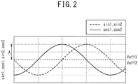
- the voltages Voff1 and Voff2 are offset voltages (in other words, DC components of the first sine-wave signal sin1, the first cosine-wave signal cos1, the second sine-wave signal sin2, and the second cosine-wave signal cos2) .
- An example of the first sine-wave signal sin1, the first cosine-wave signal cos1, the second sine-wave signal sin2 and the second cosine-wave signal cos2 are illustrated in FIG. 2 .
- the controller 40 calculates the rotation angle ⁇ m of the motor rotation shaft of the motor 20 based on the first sine-wave signal sin1, the first cosine-wave signal cos1, the second sine-wave signal sin2, and the second cosine-wave signal cos2.
- the controller 40 calculates the rotation angle ⁇ o of the output shaft 2o of the column shaft based on the rotation angle ⁇ m of the motor rotation shaft of the motor 20 and the gear ratio Rg of the reduction gear 3.
- the controller 40 calculates the rotation angle ⁇ i of the input shaft 2i of the column shaft, in other words, the steering angle ⁇ s of the steering wheel 1, based on the rotation angle ⁇ o and the steering torque Th.
- the steering torque Th that is caused by a driver operating the steering handle and transmitted from the steering wheel 1 is detected by the torque sensor 10, and the motor 20 is driven and controlled by the steering assistance command value calculated based on the steering torque Th and the vehicle speed Vh, and the assistance force (steering assistance force) for the steering wheel operation by the driver is provided to the steering system.
- FIG. 3 is an exploded diagram illustrating an outline of the exemplary sensor unit 30.
- the sensor unit 30 includes a magnet 31 and a circuit substrate 32.
- the magnet 31 is fixed to an end 24 that is the opposite of the output end 22 of the motor rotation shaft 21 of the motor 20 and has different poles (south pole and north pole) that are arranged along the circumferential direction of the motor rotation shaft 21.
- a first sensor 33 and a second sensor 34 that output a first sensor signal and a second sensor signal respectively in accordance with the rotation of the motor rotation shaft 21 of the motor 20 by detecting the magnetic flux generated by the magnet 31 are mounted on the circuit substrate 32.
- the first sensor signal that is output from the first sensor 33 includes a first sine-wave signal sin1 and a first cosine-wave signal cos1.
- the second sensor signal that is output from the second sensor 34 includes a second sine-wave signal sin2 and a second cosine-wave signal cos2.
- the first sensor 33 and the second sensor 34 may be MR sensors (for example, Tunnel Magneto Resistance (TMR) sensors) that detect magnetic flux, for example.
- MR sensors for example, Tunnel Magneto Resistance (TMR) sensors
- the first sensor 33 and the second sensor 34 are arranged near the magnet 31 that rotates with the motor rotation shaft 21, and respectively generate the first sine-wave signal sin1 and the first cosine-wave signal cos1 and the second sine-wave signal sin2 and the second cosine-wave signal cos2 in accordance with the rotation of the motor rotation shaft 21 by detecting the magnetic flux generated by the magnet 31.
- the sensor unit 30 is formed as a unit separate from the controller 40, and connected to the controller 40 by a harness 35.
- the controller 40 supplies the first sensor power source Vs1 and a second sensor power source Vs2 that respectively drive the first sensor 33 and the second sensor 34 to the sensor unit 30 via the harness 35.
- the sensor unit 30 outputs the first sensor signal and the second sensor signal to the controller 40 via the harness 35.
- the length of the harness 35 may be 10 cm, for example.
- the sensor unit 30 and the controller 40 may be formed as a single unit.
- the first sensor 33 and the second sensor 34 may be built directly into the controller 40, and the controller 40 may be attached to an end opposite from the output end 22 of the motor 20.
- the configuration of the sensor unit 30 is not limited to the configuration illustrated in FIG. 3 .
- the first sensor 33 and the second sensor 34 of the sensor unit 30 may be a sensor of a type other than MR sensor.
- the first sensor 33 may be any sensor that outputs a signal in accordance with a rotation of the motor rotation shaft 21.
- the second sensor 34 may be any sensor that outputs a sine-wave signal and a cosine-wave signal in accordance with a rotation of the motor rotation shaft 21.
- the controller 40 includes a power management unit 50 and a Micro-Processing Unit (MPU) 60.
- MPU Micro-Processing Unit
- the power management unit 50 is supplied with battery power Vbat from the battery 14, and manage the power of the sensor unit 30 and the controller 40.
- the power management unit 50 may be implemented as a single Integrated Circuit (IC) chip.
- the power management unit 50 may be a power management Integrated Circuit (IC), for example.
- the power management unit 50 generates the first sensor power source Vs1 for driving the first sensor 33, the second sensor power source Vs2 for driving the second sensor 34, a power source Vm for driving the MPU60, the controller 40 and other components (hereinafter may be referred to as MPU60, etc.) from the power supplied from the battery 14, based on the ignition key signal IG.
- the voltage of the first sensor power source Vs1, the second sensor power source Vs2, and the power source Vm may be a common power voltage Vcc1 (not illustrated), for example.
- the power voltage Vcc1 may be 5 V, for example.
- the power management unit 50 supplies the first sensor power source Vs1, the second sensor power source Vs2, and the power source Vm, to the first sensor 33, the second sensor 34, and the MPU 60, etc. , respectively while the ignition key 11 is on.
- the power management unit 50 stops providing the first sensor power source Vs1 and the power source Vm to the first sensor 33 and the MPU 60, etc. while the ignition key 11 is off.
- the power management unit 50 supplies the second sensor power source Vs2 to the second sensor 34 intermittently at a predetermined cycle T.
- the voltage of the second sensor power source Vs2 that is supplied while the ignition key 11 is off may be lower than the voltage Vcc1 while the ignition key 11 is on.
- the power management unit 50 generates rotation number information representing a rotation number by detecting the rotation number of the motor rotation shaft 21 based on the second sine-wave signal sin2 and the second cosine-wave signal cos2.
- the rotation number information includes the sine count value CNTs counting the change of the sign of the second sine-wave signal sin2, and the cosine count value CNTc counting the change of the sign of the second cosine-wave signal cos2.
- the sine count value CNTs and the cosine count value CNTc change according to the combination of the sign of the second sine-wave signal sin2 and the sign of the second cosine-wave signal cos2. The details of the power management unit 50 will be described later.
- the MPU 60 calculates the steering assistance command value of the assistance command using an assistance map, etc. based on the steering torque Th detected by the torque sensor 10 and the vehicle speed Vh detected by a vehicle speed sensor 12 and controls the driving current I of the motor 20.
- the MPU 60 calculates angular position information ⁇ 1 representing an angular position of the motor rotation shaft 21 based on the first sine-wave signal sin1 and the first cosine-wave signal cos1.
- the MPU 60 calculates rotation angle information ⁇ m representing a rotation angle of the motor rotation shaft 21 based on the rotation number information (the sine count value CNTs and the cosine count value CNTc) generated by the power management unit 50 and the angular position information ⁇ 1.
- the rotation angle information ⁇ m represents the rotation angle within the angular range of multiple turns that is more than one rotation of the motor rotation shaft 21.
- the MPU 60 stops operation.
- the MPU 60 When the ignition key 11 is turned on from off, the MPU 60 reads the rotation number information from the power management unit 50 and calculates the rotation angle information ⁇ m based on the rotation number information and the angular position information ⁇ 1.
- the MPU 60 While the ignition key 11 is on, the MPU 60 accumulates the change of the angle of the angular position information ⁇ 1 after the time at which the ignition key 11 is turned on from off to the rotation angle information ⁇ m calculated when the ignition key 11 is turned on from off, and calculates the rotation angle information ⁇ m after the ignition key 11 is turned on from off.
- the MPU 60 calculates the rotation angle ⁇ o of the output shaft 2o of the column shaft by multiplying the rotation angle information ⁇ m by the gear ratio Rg of the reduction gear 3. Based on the steering torque Th detected by the torque sensor 10, the torsion angle ⁇ t of the torsion bar arranged at the column shaft is calculated, and the rotation angle ⁇ i of the input shaft 2i of the column shaft (steering angle ⁇ s of the steering wheel 1) is calculated by adding the torsion angle ⁇ t to the rotation angle ⁇ o of the output shaft 2o.
- the controller 40 may control the steering assistance force that is applied to the output shaft 2o by the motor 20 based on the rotation angle information of the rotation angle ⁇ o of the output shaft 2o and the rotation angle ⁇ i of the input shaft 2i. For example, the controller 40 may determine whether the column shaft is in a state in which the steering wheel is steered to the end or not based on the rotation angle information. When the column shaft is in a state in which the steering wheel is steered to the end, the controller 40 may limit the driving current I of the motor 20 and may correct to reduce the steering assistance force. The controller 40 may use the rotation angle information of the rotation angle ⁇ i of the input shaft 2i for the determination of whether the input shaft 2i is in a neutral position.
- the controller 40 may determine whether the driver further turns the steering wheel 1 or the driver returns the steering wheel 1 based on the rotation angle information. For example, the controller 40 may determine whether the driver further turns the steering wheel or the driver returns the steering wheel based on the rotation angle of the column shaft and its changing direction. The controller 40 may determine whether the driver further turns the steering wheel or the driver returns the steering wheel based on the rotation angle of the column shaft and the steering torque Th.
- the controller 40 may increase and correct the driving current I to increase the steering assistance force when the driver further turns the steering wheel, and decrease and correct the driving current I to decrease the steering assistance force when the driver returns the steering wheel. More details of the MPU 60 will be described later.
- the power management unit 50 includes a regulator 51, a first power supply unit 52, a second power supply unit 53, a third power supply unit 54, a power control unit 56, and a rotation number detection unit 58.
- the regulator 51, the first power supply unit 52, the second power supply unit 53, the third power supply unit 54 and the power control unit 56 are an example of a "power supply unit" described in the claims.
- the regulator 51 generates regulator power source VR having a predetermined voltage from the battery power source Vbat.
- the voltage of the regulator power source VR is 6 V, for example.
- the first power supply unit 52, the second power supply unit 53, and the third power supply unit 54 generate the power source Vm, the first sensor power source Vs1, and the second sensor power source Vs2, respectively from the regulator power source VR.
- the power source Vm and the first sensor power source Vs1 may be made common, and the first power supply unit 52 and the second power supply unit 53 may become a single power supply unit.
- the first sensor 33 and the MPU 60, etc. may be supplied with power from one or a plurality of power supply units.
- the power control unit 56 outputs control signals Sc1, Sc2, and Sc3 to the first power supply unit 52, the second power supply unit 53 and the third power supply unit 54, respectively, based on the ignition key signal IG and controls the first power supply unit 52, the second power supply unit 53, and the third power supply unit 54.
- the power control unit 56 makes the first power supply unit 52, the second power supply unit 53, and the third power supply unit 54 generate the power source Vm, the first sensor power source Vs1, and the second sensor power source Vs2, respectively.
- the first power supply unit 52 continually supplies power source Vm to the MPU 60, etc.
- the second power supply unit 53 continually supplies the first sensor power source Vs1 to the first sensor 33.
- the third power supply unit 54 continually supplies the second sensor power source Vs2 to the second sensor 34 and the rotation number detection unit 58. Therefore, the MPU 60, etc., the first sensor 33, the second sensor 34, and the rotation number detection unit 58 operate continually.
- the power control unit 56 stops the first power supply unit 52 and the second power supply unit 53. In other words, the generation of the power source Vm and the first sensor power source Vs1 is stopped. Accordingly, the supply of the first sensor power source Vs1 to the first sensor 33 and the supply of the power source Vm to the MPU 60, etc. are stopped, and the operation of the first sensor 33 and the MPU 60, etc. stop.
- the power control unit 56 makes the third power supply unit 54 generate the second sensor power source Vs2 intermittently in a predetermined cycle T. Therefore, the second sensor power source Vs2 is intermittently supplied to the second sensor 34 and the rotation number detection unit 58. The second sensor 34 and the rotation number detection unit 58 operate intermittently in a predetermined cycle T.
- the power control unit 56 may set the voltage of the second sensor power source Vs2 that is supplied while the ignition key 11 is off to be lower than the while the ignition key 11 is on.
- the rotation number detection unit 58 generates rotation number information (in other words, the sine count value CNTs and the cosine count value CNTc) representing a rotation number by detecting the rotation number of the motor rotation shaft 21 based on the second sine-wave signal sin2 and the second cosine-wave signal cos2.
- the rotation number detection unit 58 includes a first comparator 58a, a second comparator 58b, sine counter 58c, and a cosine counter 58d.
- the first comparator 58a generates a sign signal Cs representing the plus/minus sign of the second sine-wave signal sin2 by comparing the second sine-wave signal sin2 and the threshold voltage Vr.
- the sign signal Cs has a value of "1" when the second sine-wave signal sin2 is equal to or greater than the threshold voltage Vr and has a value of "0" when the second sine-wave signal sin2 is less than the threshold voltage Vr.
- the second comparator 58b generates a sign signal Cc representing the plus/minus sign of the second cosine-wave signal cos2 by comparing the second cosine-wave signal cos2 and the threshold voltage Vr.
- the sign signal Cc has a value of "1" when the second cosine-wave signal cos2 is equal to or greater than the threshold voltage Vr, and has a value of "0" when the second cosine-wave signal cos2 is less than the threshold voltage Vr.
- the threshold voltage Vr may be set to the offset voltage Voff2, for example.
- the waveform in the broken line in FIG. 6A represents the second sine-wave signal sin2, and the waveform in the solid line represents the second cosine-wave signal cos2.
- the amplitude A of the second sine-wave signal sin2 and the second cosine-wave signal cos2 of the embodiment is one-half of the voltage of the second sensor power source Vs2 (in other words, Vs2/2), and the DC component is offset by one-half of the voltage of the second sensor power source Vs2, and the second sine-wave signal sin2 and the second cosine-wave signal cos2 change in the range of 0 V to the voltage of the second sensor power source Vs2 (in other words, Vs2) . Therefore, the threshold voltage Vr is set to one-half of the second sensor power source Vs2 (in other words, Vs2/2) .
- the sign signal Cs of the second sine-wave signal sin2 output from the first comparator 58a has a value of "1" when the angular position of the motor rotation shaft 21 is in the range of 0 deg to 180 deg and has a value of "0" in the range of 180 deg to 360 deg.
- the sign signal Cc of the second cosine-wave signal cos2 output from the second comparator 58b has a value of "1" when the angular position of the motor rotation shaft 21 is in the range of 0 deg to 90 deg and 270 deg to 360 deg and has a value of "0" in the range of 90 deg to 270 deg.
- the sine counter 58c and the cosine counter 58d count the change of the combination of the signs of the second sine-wave signal sin2 and the second cosine-wave signal cos2 based on the sign signal Cs of the second sine-wave signal sin2 and the sign signal Cc of the second cosine-wave signal cos2, and calculates the sine count value CNTs and the cosine count value CNTc, respectively.
- the sine counter 58c calculates the sine count value CNTs by counting the number of changes of the sign of the second sine-wave signal sin2, and the cosine counter 58d calculates the cosine count value CNTc by counting the number of changes of the sign of the second cosine-wave signal cos2.
- the sine counter 58c and the cosine counter 58d store the calculated sine count value CNTs and the cosine count value CNTc in a non-volatile memory (not illustrated), for example.
- the sine counter 58c increases the sine count value CNTs by 1 when the value of the sign signal Cs of the second sine-wave signal sin2 changes from “0" to "1” while the sign signal Cc of the second cosine-wave signal cos2 has a value of "1", and decreases the sine count value CNTs by 1 when the value of the sign signal Cs of the second sine-wave signal sin2 changes from "1" to "0".
- the sine counter 58c increases the sine count value CNTs by 1 when the value of the sign signal Cs of the second sine-wave signal sin2 changes from “1" to "0" while the sign signal Cc of the second cosine-wave signal cos2 has a value of 0, and decreases the sine count value CNTs by 1 when the value of the sign signal Cs of the second sine-wave signal sin2 changes from "0" to "1".
- the cosine counter 58d increases the cosine count value CNTc by 1 when the value of the sign signal Cc of the second cosine-wave signal cos2 changes from “0" to "1" while the sign signal Cs of the second sine-wave signal sin2 has a value of "0", and decreases the cosine count value CNTc by 1 when the value of the sign signal Cc of the second cosine-wave signal cos2 changes from "1" to "0".
- the cosine counter 58d increases the cosine count value CNTc by 1 when the value of the sign signal Cc of the second cosine-wave signal cos2 changes from “1" to "0" while the sign signal Cs of the second sine-wave signal sin2 has a value of "1", and decreases the cosine count value CNTc by 1 when the value of the sign signal Cc of the second cosine-wave signal cos2 changes from "0" to "1".
- the sine count value CNTs and the cosine count value CNTc increase or decrease by 2, depending on the rotation direction. Therefore, when the motor rotation shaft 21 makes one rotation, the sum of the sine count value CNTs and the cosine count value CNTc (hereinafter may be expressed as "total count value CNT") increases or decreases by 4, depending on the rotation direction, as illustrated in FIG. 6E . Accordingly, the combination of the sine count value CNTs and the cosine count value CNTc and the total count value CNT represent the rotation number in quarters of a rotation. The combination of sine count value CNTs and the cosine count value CNTc and the total count value CNT represent which of the 4 quadrants made by dividing into four the rotation range of the motor rotation shaft 21 the angular position of the motor rotation shaft 21 belongs to.
- the sine count value CNTs and the cosine count value CNTc of the embodiment are merely an example, and the rotation number information of the present invention is not limited to the sine count value CNTs and the cosine count value CNTc.
- the rotation number information may be any rotation number information representing the rotation number in units of 1/n rotations where n is a natural number of 2 and more.
- the MPU 60 includes an angular position calculation unit 61, a count total unit 62, a rotation number information correction unit 63, a rotation number calculation unit 64, a torsion angle calculation unit 65, a rotation angle information calculation unit 66, a diagnosis unit 67, and an assist control unit 68.
- the functions of the angular position calculation unit 61, the count total unit 62, the rotation number information correction unit 63, the rotation number calculation unit 64, the torsion angle calculation unit 65, the rotation angle information calculation unit 66, the diagnosis unit 67, and the assist control unit 68 are realized by MPU 60 executing a program stored in a storage device (a non-volatile memory, etc. for example) included by the MPU 60 or the controller 40.
- a storage device a non-volatile memory, etc. for example
- the rotation angle information calculation unit 66 is an example of the “rotation angle calculation unit” and the “steering angle calculation unit” described in the claims.
- the assist control unit 68 is an example of the "motor control unit” described in the claims.
- the angular position calculation unit 61 takes the first sine-wave signal sin1 and the first cosine-wave signal cos1 as inputs, and compensates the error included in these signals (offset, amplitude difference, phase difference, etc.) .
- FIG. 8A illustrates an example of the first sine-wave signal sin1 and the first cosine-wave signal cos1.
- An example of the angular position information ⁇ 1 is illustrated in FIG. 8B .
- the angular position calculation unit 61 may calculate the angular position information ⁇ 1 based on the sum of the first sine-wave signal sin1 and the first cosine-wave signal cos1 (cos1 + sin1) and the difference (cos1 - sin1).
- the count total unit 62 reads the sine count value CNTs and the cosine count value CNTc respectively from the sine counter 58c and the cosine counter 58d of the power management unit 50 when the supply of the power source Vm to the MPU 60 starts (in other words, when the ignition key 11 is turned on from off) .
- the count total unit 62 adds the sine count value CNTs and the cosine count value CNTc and calculates the total count value CNT as illustrated in FIG. 6E .
- an error may occur to the sine count value CNTs and the cosine count value CNTc due to an error included in the second sine-wave signal sin2 and the second cosine-wave signal cos2 and an error in the threshold voltage of the comparator Vr.
- the total count value CNT may include an error.
- the rotation number information correction unit 63 compensates for the error generated in the total count value CNT by correcting the total count value CNT based on the angular position information ⁇ 1.
- the rotation number information correction unit 63 outputs the corrected total count value CNTa in which the error is compensated. The details of the rotation number information correction unit 63 will be described later.
- the rotation number calculation unit 64 calculates the rotation number Nr of the motor rotation shaft 21 as the quotient obtained by dividing the corrected total count value CNTa by a natural number n.
- the natural number n is the number of increases/decreases of the total count value CNT per one rotation of the motor rotation shaft 21, and the natural number n is 4 in this embodiment.
- An example of the rotation number Nr is illustrated in FIG. 8C .
- the torsion angle calculation unit 65 calculates the torsion angle ⁇ t of the torsion bar arranged on the column shaft based on the steering torque Th detected by the torque sensor 10.
- the rotation angle information calculation unit 66 calculates the rotation angle information ⁇ m in the range of multiple rotations of equal to or more than one rotation of the motor rotation shaft 21 based on the rotation number Nr calculated by the rotation number calculation unit 64 and the angular position information ⁇ 1 calculated by the angular position calculation unit 61 when the supply of the power source Vm to the MPU 60 is started (in other words, the ignition key 11 is turned on from off) .
- An example of the rotation angle information ⁇ m is illustrated in FIG. 8D .
- the rotation angle information calculation unit 66 accumulates the change of the angle of the angular position information ⁇ 1 after the time at which the ignition key 11 is turned on from off to the rotation angle information ⁇ m calculated when the ignition key 11 is turned on from off, and calculates the rotation angle information ⁇ m after the ignition key 11 is turned on from off.
- the multiplier 66c calculates the rotation angle ⁇ o of the output shaft 2o of the column shaft by multiplying the rotation angle information ⁇ m by the gear ratio Rg of the reduction gear 3.
- the adder 66d calculates the rotation angle ⁇ i (the steering angle ⁇ s of the steering wheel 1) of the input shaft 2i of the column shaft by adding the torsion angle ⁇ t of the torsion bar to the rotation angle ⁇ o.
- the rotation angle information calculation unit 66 outputs the rotation angle information including the rotation angle ⁇ o and the rotation angle ⁇ i.
- the rotation angle information including the rotation angle ⁇ o of the output shaft 2o and the rotation angle ⁇ i of the input shaft 2i can be used for the determination by the controller 40 whether the column shaft is steered to an end or not and the determination whether the driver further turns the steering wheel 1 or returns the steering wheel.
- the controller 40 may control the steering assistance force that is applied to the output shaft 2o by the motor 20 based on these determination results.
- the rotation angle information of the rotation angle ⁇ i of the input shaft 2i may be used for the determination of whether the input shaft 2i is in a neutral position.
- the diagnosis unit 67 determines the abnormality that occurred in the first sensor 33 or the second sensor 34 by comparing the angular position information ⁇ 1 calculated based on the first sine-wave signal sin1 and the first cosine-wave signal cos1 and the angular position information ⁇ 2 calculated based on the second sine-wave signal sin2 and the second cosine-wave signal cos2. For example, when the difference between the angular position information ⁇ 1 and the angular position information ⁇ 2 is equal to or greater than a threshold value, the diagnosis unit 67 determines that an abnormality has occurred in the first sensor 33 or the second sensor 34.
- the diagnosis unit 67 determines an abnormality that occurred in the second sensor 34 or the rotation number detection unit 58 based on the difference between the sine count value CNTs and the cosine count value CNTc. For example, the diagnosis unit 67 determines an abnormality has occurred in the second sensor 34 or the rotation number detection unit 58 when the difference between the sine count value CNTs and the cosine count value CNTc is equal to or greater than 2.
- the diagnosis unit 67 outputs a diagnosis signal Sd representing the determination result to the assist control unit 68.
- the assist control unit 68 controls the driving current I of the motor 20 based on the steering torque Th detected by the torque sensor 10 and the vehicle speed Vh detected by the vehicle speed sensor 12.
- FIG. 9 illustrates an exemplary functional configuration of the assist control unit 68.
- the steering torque Th detected by the torque sensor 10 and the vehicle speed Vh detected by the vehicle speed sensor 12 are input to a current command value calculation unit 71 that calculates the current command value Iref1.
- the current command value calculation unit 71 calculates the current command value Iref1 that is the target value of the current to be supplied to the motor 20 based on the input steering torque Th and the vehicle speed Vh using an assistance map, etc.
- the voltage control command value Vref whose characteristic is improved by the PI control unit 75 is input to the PWM control unit 76, and the motor 20 is PWM driven via an inverter 77 as the driver.
- the current value Im of the motor 20 is detected by the motor current detector 78 and fed back to the subtraction unit 72B.
- a compensation signal CM from a compensation signal generation unit 74 is added to the addition unit 72A, and the characteristics of the steering system are compensated by adding the compensation signal CM, thereby improving astringency and inertial characteristics, etc.
- the compensation signal generation unit 74 adds the self-aligning torque (SAT) 74-3 and the inertia 74-2 at the addition unit 74-4, and further adds the astringency 74-1 at the addition unit 74-5, and the result of the addition by the addition unit 74-5 is the compensation signal CM.
- SAT self-aligning torque
- the assist control unit 68 performs a predetermined abnormality handling processing such as stopping driving the motor 20 and outputting alarm when an occurrence of abnormality is detected based on the diagnosis signal Sd output by the diagnosis unit 67.
- the rotation number information correction unit 63 is described. As described above, an error may occur to the total count value CNTs output from the rotation number calculation unit 64 due to the error included in the second sine-wave signal sin2 and the second cosine-wave signal cos2 and the error in the threshold voltage of the comparator Vr.
- FIG. 10A illustrates an example of the second sine-wave signal sin2 and the second cosine-wave signal cos2, and the threshold voltage Vr of the first comparator 58a and the second comparator 58b.
- the broken line represents the second sine-wave signal sin2
- the solid line represents the second cosine-wave signal cos2
- the two-dot chain line represents the threshold voltage Vr that is compared with the second sine-wave signal sin2 at the first comparator 58a
- the dashed line represents the threshold voltage Vr that is compared with the second cosine-wave signal cos2 at the second comparator 58b.
- the threshold voltage Vr two-dot chain line
- the design value ideal value
- the sine count value CNTs and the cosine count value CNTc will be as illustrated in FIG. 10B .
- the broken line represents the sine count value CNTs, and the solid line represents the cosine count value CNTc.
- the rotation number information correction unit 63 corrects the gap in the rise (fall) timing of the total count value CNT illustrated in FIG. 10C .
- the rotation number information correction 63 includes a first quadrant information calculation unit 63a, a second quadrant information calculation unit 63b, a quadrant comparison unit 63c, and a correction unit 63d.
- the first quadrant information calculation unit 63a calculates first quadrant information Q1 representing which of the quadrants formed by dividing the rotation range of the motor rotation shaft 21 by the above-described natural number n the angular position of the motor rotation shaft 21 belongs to based on the angular position information ⁇ 1.
- the second quadrant information calculation unit 63b calculates second quadrant information Q2 representing which of the quadrants formed by dividing the rotation range of the motor rotation shaft by the above-described natural number n the angular position of the motor rotation shaft 21 belongs to based on the total count value CNT that is the rotation number information.
- the natural number n is the number of increases/decreases of the total count value CNT per one rotation of the motor rotation shaft 21, and in the embodiment, the natural number n is "4".
- the first quadrant information Q1 and the second quadrant information Q2 represent which of the first quadrant, the second quadrant, the third quadrant, and the fourth quadrant the angular position of the motor rotation shaft 21 belongs to.
- the first quadrant information calculation unit 63a may calculate the first quadrant information Q1 by performing a threshold determination of which of the first quadrant to the nth quadrant the angular position information ⁇ 1 belongs to.
- the second quadrant information calculation unit 63b may calculate the second quadrant information Q2 as the remainder (modulo: CNT mod n) when the total count value CNT is divided by the natural number n.
- FIG. 13A illustrates an example of the first quadrant information Q1 and the second quadrant information Q2.
- the solid line illustrates the first quadrant information Q1 and the broken line illustrates the second quadrant information Q2. Due to the gap of the rise (fall) timing of the total count value CNT illustrated in FIG. 10C , a difference is generated between the first quadrant information Q1 and the second quadrant information Q2 in the places enclosed by the dashed line.
- the quadrant comparison unit 63c outputs a quadrant difference representing a comparison result of comparing the first quadrant information Q1 and the second quadrant information Q2.
- the quadrant comparison unit 63c may calculate the difference by subtracting the number indicating the quadrant of the second quadrant information Q2 from the number indicating the quadrant of the first quadrant information Q1 as the quadrant difference in accordance with the following equation (1).
- Quadrant difference Q2 ⁇ Q 1
- the quadrant difference is calculated by adding 4 (i.e., the natural number n) to the subtraction result, in accordance with the following equation (2).
- the quadrant difference is calculated by subtracting 4 (i.e., the natural number n) from the subtraction result, in accordance with the following equation (3).
- FIG. 13B represents an example of the quadrant difference.
- the quadrant difference takes one of the values 1, 0, and -1.
- the correction unit 63d calculates the corrected total count value CNTa by correcting the total count value CNT in accordance with the quadrant difference output by the quadrant comparison unit 63c.
- the correction unit 63d calculates the corrected total count value CNTa by subtracting the quadrant difference from the total count value CNT.
- FIG. 13C illustrates the corrected total count value CNTa calculated by subtracting the quadrant difference of FIG. 13B from the total count value CNT of FIG. 10C .
- FIG. 13D is obtained by calculating the motor rotation number Nr based on the corrected total count value CNTa.
- the motor rotation number Nr in FIG. 13D is similar to the motor rotation number Nr of FIG. 8C , indicating that the error is corrected.
- the power control unit 56 of the power management unit 50 stops the first power supply unit 52 and the second power supply unit 53, and only the third power supply unit 54 operates. At this time, the power control unit 56 makes the third power supply unit 54 generate the second sensor power source Vs2 intermittently in a predetermined cycle T.
- the second sensor power source Vs2 is intermittently supplied to the second sensor 34 and the rotation number detection unit 58.
- the second sensor 34 and the rotation number detection unit 58 operate intermittently in a predetermined cycle T.
- the sine counter 58c increments or decrements the sine count value CNTs in accordance with the output of the first comparator 58a.
- the cosine counter 58d increments or decrements the cosine count value CNTc in accordance with the output of the second comparator 58b.
- the power control unit 56 starts operation of the first power supply unit 52 and the second power supply unit 53.
- the power control unit 56 makes the first power supply unit 52, the second power supply unit 53, and the third power supply unit 54 continually generate the power source Vm, the first sensor power source Vs1, and the second sensor power source Vs2.
- the power source Vm, the first sensor power source Vs1, the second sensor power source Vs2 are started to be continually supplied to the MPU 60, etc., the first sensor 33, the second sensor 34, and the rotation number detection unit 58.
- the first sensor 33, the second sensor 34, and the rotation number detection unit 58 operate continually.
- the count total unit 62 of the MPU 60 reads the sine count value CNTs and the cosine count value CNTc respectively from the sine counter 58c and the cosine counter 58d and calculates the total count value CNT when the ignition key 11 is turned on from off.
- the rotation number information correction unit 63 outputs the corrected total count value CNTa by correcting the total count value CNT, and the rotation number calculation unit 64 calculates the rotation number Nr of the motor rotation shaft 21 from the corrected total count value CNTa.
- the angular position calculation unit 61 calculates the angular position information ⁇ 1 and based on the rotation number Nr and angular position information ⁇ 1, the rotation angle information calculation unit 66 calculates the rotation angle information ⁇ m of the motor rotation shaft 21.
- the power control unit 56 operates the first power supply unit 52, the second power supply unit 53, and the third power supply unit 54 and makes them continually generate the power source Vm, the first sensor power source Vs1, and the second sensor power source Vs2.
- the MPU 60, etc., the first sensor 33, the second sensor 34, and the rotation number detection unit 58 operate continually.
- the rotation number detection unit 58 periodically measures the output of the first comparator 58a and the second comparator 58b and maintains the sine count value CNTs and the cosine count value CNTc (in other words, the current value of the motor rotation number) by incrementing or decrementing the sine count value CNTs and the cosine count value CNTc.
- the angular position calculation unit 61 calculates the angular position information ⁇ 1.
- the rotation angle information calculation unit 66 accumulates the change of the angle of the angular position information ⁇ 1 after the time at which the ignition key 11 is turned on from off to the rotation angle information ⁇ m calculated when the ignition key 11 is turned on from off and calculates the rotation angle information ⁇ m after the ignition key 11 is turned on from off.
- the rotation angle information calculation unit 66 calculates the rotation angle ⁇ o of the output shaft 2o of the column shaft and the rotation angle ⁇ i of the input shaft 2i based on the rotation angle information ⁇ m, the gear ratio Rg of the reduction gear 3, and the torsion angle ⁇ t of the torsion bar.
- the assist control unit 68 controls the driving current I of the motor 20 based on the steering torque Th detected by the torque sensor 10 and the vehicle speed Vh detected by the vehicle speed sensor 12.
- the diagnosis unit 67 determines whether or not an abnormality has occurred in the first sensor 33 or the second sensor 34 by comparing the angular position information ⁇ 1 and the angular position information ⁇ 2.
- the diagnosis unit 67 determines whether or not an abnormality that occurred in the second sensor 34 or the rotation number detection unit 58 based on the difference between the sine count value CNTs and the cosine count value CNTc.
- the assist control unit 68 performs a predetermined abnormality handling processing such as stopping driving the motor 20 and outputting an alarm when an occurrence of abnormality is detected based on the diagnosis signal Sd output by the diagnosis unit 67.
- the steering angle of the steering shaft can be detected using the rotation angle information of the motor rotation shaft 21 of the motor 20 without installing an angle sensor that detects the steering angle of the steering shaft.
- the steering assistance force applied to the steering shaft by the motor 20 can be controlled based on the steering angle calculated by the rotation angle information calculation unit 66.
- a power management unit 50 according to the second embodiment is described.
- the power management unit 50 of the second embodiment generates an internal power source Vp (refer to FIG. 14 ) for driving a digital logical circuit inside the power management unit 50 in addition to the first sensor power source Vs1, the second sensor power source Vs2, and the power source Vm based on the ignition key signal IG from the power supplied from the battery 14.
- the power management unit 50 supplies power source Vm to the MPU 60, etc. in a similar manner to the first embodiment.
- the power management unit 50 supplies the first sensor power source Vs1 and the second sensor power source Vs2 to the first sensor 33 and the second sensor 34, respectively.
- the power management unit 50 continually supplies the internal power source Vp to the logical circuit inside the power management unit 50, regardless of whether the ignition key 11 is on or off.
- the power management unit 50 stops providing the first sensor power source Vs1 and the power source Vm to the first sensor 33 and the MPU 60, etc. while the ignition key 11 is off.
- the power management unit 50 supplies the second sensor power source Vs2 to the second sensor 34 intermittently.
- the voltage of the second sensor power source Vs2 that is supplied intermittently while the ignition key 11 is off may be the power voltage Vcc2 that is lower than the power voltage Vcc1.
- the power voltage Vcc2 may be 3.3 V, for example.
- the threshold voltage Vr is set to one-half of the second sensor power source Vs2 (in other words, Vs2/2). Therefore, for example, when the ignition key 11 is on and the second sensor power source Vs2 is 5 V, the threshold voltage Vr may be set to 2.5 V, and when the ignition key 11 is off and the second sensor power source Vs2 is 3.3 V, the threshold voltage Vr may be set to 1.65 V.
- FIG. 14 is a block diagram of an exemplary functional configuration of a power management unit 50 of the second embodiment. A component similar to that of the power management unit 50 of the first embodiment is indicated with the same reference sign.
- a power management unit 50 of the second embodiment includes an internal power generation unit 55 and a sensor power determination unit 57.
- the third power supply unit 54 is an example of a "sensor power supply unit”.
- the first power supply unit 52, the second power supply unit 53 and the internal power generation unit 55 are an example of a "power supply unit" described in the claims.
- the power control unit 56 generates an operation switching signal Sig based on the ignition key signal IG and outputs to the regulator 51, the first power supply unit 52, the second power supply unit 53, and the third power supply unit 54.
- the operation switching signal Sig has a different value in accordance with whether the ignition key 11 is on or off.
- the operation switching signal Sig represents whether the ignition key 11 is on or off.
- the value representing that the ignition key 11 is on may be "1"
- the value representing that the ignition key 11 is off may be "0".
- the power control unit 56 generates a drive interval instruction signal Si and outputs to the third power supply unit 54.
- the drive interval instruction signal Si is a signal that indicates the interval of intermittently supplying power to the second sensor while the ignition key 11 is off, in other words, a signal that indicates the drive interval of driving the second sensor 34. The details of the power control unit 56 will be described later.
- the regulator 51 generates regulator power source VR having a predetermined voltage from the battery power source Vbat.
- the first power supply unit 52, the second power supply unit 53, the third power supply unit 54, and the internal power generation unit 55 generate the power source Vm, the first sensor power source Vs1, the second sensor power source Vs2, and the internal power source Vp respectively from the regulator power source VR.
- the regulator 51 switches the voltage of the regulator power source VR in accordance with the operation switching signal Sig.
- the voltage of the regulator power source VR while the operation switching signal Sig is "1" may be 6 V
- the voltage of the regulator power source VR while the operation switching signal Sig is "0" in other words, while the ignition key 11 is off
- the voltage of the regulator power source VR while the operation switching signal Sig is "0" in other words, while the ignition key 11 is off
- the first power supply unit 52 continually supplies power source Vm to the MPU 60, etc. while the operation switching signal Sig has the value of "1".
- the second power supply unit 53 continually supplies the first sensor power source Vs1 to the first sensor 33, and the third power supply unit 54 continually supplies the second sensor power source Vs2 to the second sensor 34.
- the first sensor 33 and the second sensor 34 operate continually.
- the voltages of the first sensor power source Vs1 and the second sensor power source Vs2 are the common power voltage Vcc1.
- the first power supply unit 52 and the second power supply unit 53 stop generating the power source Vm and the first sensor power source Vs1. Accordingly, the supply of the first sensor power source Vs1 to the first sensor 33 and the supply of the power source Vm to the MPU 60, etc. are stopped, and the operation of the first sensor 33 and the MPU 60, etc. stops.
- the third power supply unit 54 generates the second sensor power source Vs2 having the power voltage Vcc2 that is lower than the power voltage Vcc1 while the operation switching signal Sig has a value of "0".
- the third power supply unit 54 intermittently generates the second sensor power source Vs2 in the drive interval instructed by the drive interval instruction signal Si while the operation switching signal Sig has a value of "0".
- the second sensor power source Vs2 having a power voltage Vcc2 that is lower than the power voltage Vcc1 is intermittently supplied to the second sensor 34, and the second sensor 34 operates intermittently.
- the internal power generation unit 55 supplies the internal power source Vp to the rotation number detection unit 58 regardless of the value of the operation switching signal Sig being "1" or "0" (regardless of the ignition key 11 being on or off).
- the sensor power determination unit 57 determines whether the second sensor power source Vs2 is supplied to the second sensor 34 in the period when the ignition key 11 is off (in other words, the period in which the second sensor power source Vs2 is generated intermittently).
- the sensor power determination unit 57 generates an activation signal Sr for operating the rotation number detection unit 58 at the timing when the second sensor power source Vs2 is supplied to the second sensor 34.
- the value of the activation signal Sr intermittently becomes "1" in the period when the second sensor power source Vs2 is supplied, and becomes "0" in the period when the second sensor power source Vs2 is not supplied, for example.
- the rotation number detection unit 58 While the ignition key 11 is on, the rotation number detection unit 58 continually operates. While the ignition key 11 is off, the rotation number detection unit 58 operates when the value of the activation signal Sr from the sensor power determination unit 57 is "1" (in other words, the second sensor power source Vs2 is supplied to the second sensor 34) . Therefore, the rotation number detection unit 58 operates intermittently.
- the first comparator 58a and the second comparator 58b of the rotation number detection unit 58 operate intermittently while the ignition key 11 is off, and changes the sign signals Cs and Cc in accordance with the result of comparing the second sine-wave signal sin2 and the second cosine-wave signal cos2 and the threshold voltage Vr.
- the internal power source Vp maintains the output of the sign signals Cs and Cc.
- the sine counter 58c and the cosine counter 58d operate using the internal power source Vp as the power source and calculate the sine count value CNTs and the cosine count value CNTc, respectively.
- the power control unit 56 is further described. As described above, the power control unit 56 controls the regulator 51, the first power supply unit 52, the second power supply unit 53, and the third power supply unit 54 by generating the operation switching signal Sig and the drive interval instruction signal Si.
- the power control unit 56 includes an action switching unit 56a and a drive interval changing unit 56b.
- the action switching unit 56a generates the operation switching signal Sig based on the ignition key signal IG.
- the drive interval changing unit 56b generates the drive interval instruction signal Si based on whether the rotation of the motor rotation shaft 21 is detected or not. As described above, the drive interval instruction signal Si instructs the drive interval for intermittently driving the second sensor 34.
- the drive interval changing unit 56b expands/shortens the drive interval instructed by the drive interval instruction signal Si in accordance with whether the rotation of the motor rotation shaft 21 is detected or not.
- the drive interval changing unit 56b shortens the drive interval instructed by the drive interval instruction signal Si from the predetermined maximum interval x when a rotation of the motor rotation shaft 21 is detected and expands the drive interval to the maximum interval x when a rotation of the motor rotation shaft 21 is no longer detected afterwards.
- the maximum interval x is an example of the "first time interval”.
- the drive interval changing unit 56b may generate the drive interval instruction signal Si in accordance with whether a change in the second sine-wave signal sin2 and the second cosine-wave signal cos2 is detected or not.
- the drive interval changing unit 56b generates the drive interval instruction signal Si based on the change of the sign signal Cs of the second sine-wave signal sin2 that is the output of the first comparator 58a and the change of the sign signal Cc of the second cosine-wave signal cos2 that is the output of the second comparator 58b.
- the drive interval changing unit 56b shortens the drive interval instructed by the drive interval instruction signal Si from the maximum interval x when a change occurs in the sign signals Cs and Cc.
- the drive interval changing unit 56b expands the drive interval instructed by the drive interval instruction signal Si to the maximum interval x when a change no longer occurs to the sign signals Cs and Cc.
- the drive interval changing unit 56b may start to expand the drive interval when the change of neither of the sign signals Cs and Cc is detected even when the power is supplied intermittently for the predetermined multiple times to the second sensor 34.
- the drive interval instructed by the drive interval instruction signal Si may be shortened by steps.
- the drive interval changing unit 56b shortens the drive interval by the predetermined length T1, and when a change in the other signal is detected afterwards, further shortens the drive interval by the predetermined length T1. Therefore, the shortening length changes by steps of T1, (2 x T1).
- FIG. 15A illustrates an example when the predetermined length T1 is 2.2 msec.
- the initial drive interval is the maximum interval x, and as represented by the reference sign 100, when the sign signal Cs changes from "0" to "1", the drive interval is shortened from the maximum interval x to (x -2.2) msec.
- the drive interval instructed by the drive interval instruction signal Si is shortened by steps from 6.6 msec to 4.4 msec, and then to 2.2 msec.
- the drive interval changing unit 56b prohibits shortening the drive interval to a value shorter than the minimum interval even when a change in the sign signals Cs and Cc is detected.
- the minimum interval may be (x - 4.4) msec.
- the maximum interval x is 6.6 msec
- the minimum interval becomes 2.2 msec.
- the time width w of the period when the second sensor power source Vs2 is supplied to the second sensor 34 may be fixed.
- the time width w may be 220 ⁇ sec, for example.
- the duty ratio of the drive period of the second sensor 34 when the drive interval is the maximum interval of 6.6 msec is 1/3 of when the drive interval is the minimum interval of 2.2 msec.
- the duty ratio is 10%.
- the motor rotation shaft 21 is not rotating fast so there is a little risk of a counting mistake of the sine count value CNTs and the cosine count value CNTc even if the drive interval is not greatly shortened.
- the drive interval changing unit 56b may be configured not to shorten the drive interval instructed by the drive interval instruction signal Si when one of the sign signals Cs and Cc changes, and then before the other of the sign signals Cs and Cc changes, the one of the sign signals Cs and Cc changes again.
- the drive interval changing unit 56b stores the change history of the sign signal Cs representing the change of the sign signal Cs when a change in the sign signal Cs is detected.
- the drive interval changing unit 56b When the change history of the sign signal Cs is stored and a change in the sign signal Cs is detected, the drive interval changing unit 56b does not shorten the drive interval by steps. On the contrary, when the change history of the sign signal Cs is not stored and a change in the sign signal Cs is detected, the drive interval changing unit 56b shortens the drive interval and stores the change history of the sign signal Cs.
- the drive interval changing unit 56b When the change history of the sign signal Cs is stored and a change in the sign signal Cc is detected, the drive interval changing unit 56b shortens the drive interval and stores the change history of the sign signal Cc. At this time, the drive interval changing unit 56b resets the change history to a state in which the change of the sign signal Cs is not stored.
- the drive interval changing unit 56b does not shorten the drive interval by steps.
- the drive interval changing unit 56b shortens the drive interval by steps and stores the change history of the sign signal Cc.
- the drive interval changing unit 56b When the change history of the sign signal Cc is stored and a change in the sign signal Cs is detected, the drive interval changing unit 56b shortens the drive interval and stores the change history of the sign signal Cs. The drive interval changing unit 56b resets the change history to a state in which the change of the sign signal Cc is not stored.
- the change history of the sign signals Cs and Cc may be stored by a flip-flop circuit, etc. when the drive interval changing unit 56b is implemented by hardware such as a logical circuit for example.
- the change history of the sign signals Cs and Cc may be stored by a flag, etc. when the drive interval changing unit 56b is realized by software.
- the drive interval changing unit 56b expands the drive interval instructed by the drive interval instruction signal Si to the maximum interval x when a change no longer occurs to the sign signals Cs and Cc after the drive interval instructed by the drive interval instruction signal Si is shortened.
- the drive interval instructed by the drive interval instruction signal Si is expanded to the maximum interval x.
- the drive interval changing unit 56b counts the power supply count CNTr that represents the number of times that power is intermittently supplied to the second sensor 34 after the last detection of the change of one of the sign signals Cs and Cc.
- the drive interval changing unit 56b increases the power supply count CNTr by 1 every time power is intermittently supplied to the second sensor 34 and resets the power supply count CNTr to 0 when a change in one of the sign signals Cs and Cc is detected.
- the drive interval changing unit 56b determines whether the power supply count CNTr is equal to or greater than a predetermined count threshold value Cth or not. When the power supply count CNTr is equal to or greater than the predetermined count threshold value Cth, the drive interval changing unit 56b expands the drive interval instructed by the drive interval instruction signal Si by a predetermined length T2 every time the power supply count CNTr increases by 1.
- the predetermined length T2 may be shorter than the above-described predetermined length T1, or may be equal to the predetermined length T1.
- the drive interval changing unit 56b resets the change history to a state in which the change of the sign signals Cs and Cc is not stored.
- the drive interval changing unit 56b continues to expand the drive interval until the drive interval reaches the maximum interval x, and when the drive interval reaches the maximum interval x, stops expanding the drive interval.
- FIG. 16A to FIG. 16D an example of controlling the drive interval of the second sensor 34 when a rotation of the motor rotation shaft 21 is not detected while the ignition key 11 is off is described.
- the count threshold value Cth is 4, and the predetermined length T2 is 1.1 msec.
- the drive interval changing unit 56b resets the power supply count CNTr to 0. Then, the drive interval changing unit 56b increases the power supply count CNTr by 1 every time power is intermittently supplied to the second sensor 34 when no change of either of the sign signals Cs and Cc is detected.
- the drive interval changing unit 56b determines whether or not the power supply count CNTr is equal to or greater than 4 which is the count threshold value Cth.
- the drive interval changing unit 56b expands the drive interval instructed by the drive interval instruction signal Si by the predetermined length T2 of 1.1 msec. As a result, the drive interval expands from (x - 4.4) msec to (x - 3.3) msec.
- the drive interval changing unit 56b expands the drive interval by 1.1 msec every time the power supply count CNTr increases by 1.
- the drive interval changing unit 56b stops expanding the drive interval.
- the numerical examples of the above-described predetermined lengths T1 and T2, the maximum interval x and the minimum interval of the drive interval, and the count threshold value Cth are merely examples, and the present invention is not limited to the above numerical examples .
- the value of the predetermined length T1, the maximum interval x and the minimum interval may be set appropriately in accordance with the actual device configuration.
- the drive interval changing unit 56b may shorten the length of shortening the drive interval to be shorter than the predetermined length T1.
- the drive interval changing unit 56b may shorten the length to expand the drive interval to be shorter than the predetermined length T2.
- step S1 the sensor power determination unit 57 determines whether a rise of the voltage of the second sensor power source Vs2 is detected or not.
- step S1: Y the process proceeds to step S2.
- step S1: N the process terminates. In this case, the drive interval does not change.
- step S2 the sensor power determination unit 57 generates the activation signal Sr and outputs to the rotation number detection unit 58.
- the rotation number detection unit 58 started by the activation signal Sr, the first comparator 58a and the second comparator 58b output the sign signal Cs of the second sine-wave signal sin2 and the sign signal Cc of the second cosine-wave signal cos2.
- the drive interval changing unit 56b performs a rotation detection process, and determines whether a rotation of the motor rotation shaft 21 is detected or not based on the sign signals Cs and Cc.
- step S2 an example of the rotation detection process in step S2 is described.
- step S20 the drive interval changing unit 56b determines whether the sign signal Cs changed or not.
- step S20: Y the process proceeds to S21.
- step S20: N the process proceeds to S25.
- step S21 the drive interval changing unit 56b determines whether the change history of the sign signal Cs representing that the sign signal Cs changed exists or not.
- step S21: Y the change history exists
- step S24 the change history does not exist
- step S21: N the process proceeds to S22.
- step S22 the drive interval changing unit 56b stores the change history of the sign signal Cs representing that the sign signal Cs changed.
- the drive interval changing unit 56b resets the change history representing the sign signal Cc changed to a state that the change of the sign signal Cc is not stored.
- step S23 the drive interval changing unit 56b determines that a rotation of the motor rotation shaft 21 is detected, and terminates the rotation detection process.
- step S21 N
- the drive interval changing unit 56b determines that a rotation of the motor rotation shaft 21 is not detected in step S24, and terminates the rotation detection process.
- step S20 N
- the drive interval changing unit 56b determines whether the sign signal Cc changed or not in step S25.
- step S25: Y When the sign signal Cc changed (step S25: Y), the process proceeds to step S26.
- step S25: N the process proceeds to S24. In this case, the drive interval changing unit 56b determines that a rotation of the motor rotation shaft 21 is not detected, and terminates the rotation detection process.
- step S26 the drive interval changing unit 56b determines whether the change history of the sign signal Cs representing that the sign signal Cc changed exists or not.
- step S26 Y
- the process proceeds to S24.
- the drive interval changing unit 56b determines that a rotation of the motor rotation shaft 21 is not detected, and terminates the rotation detection process.
- step S26: N the process proceeds to S27.
- step S27 the drive interval changing unit 56b stores the change history of the sign signal Cc representing that the sign signal Cc changed.
- the drive interval changing unit 56b resets the change history representing the sign signal Cs changed to a state that the change of the sign signal Cs is not stored.
- step S28 the drive interval changing unit 56b determines that a rotation of the motor rotation shaft 21 is detected, and terminates the rotation detection process.
- step S3: Y When a rotation of the motor rotation shaft 21 is detected (step S3: Y), the process proceeds to S4. When a rotation of the motor rotation shaft 21 is not detected (step S3: N), the process proceeds to S7.
- step S4 the drive interval changing unit 56b resets the power supply count CNTr counting the number of times power is intermittently supplied to the second sensor 34.
- step S5 the drive interval changing unit 56b determines whether the drive interval instructed by the drive interval instruction signal Si is already the minimum interval. When the drive interval is the minimum interval (step S5: Y), the process terminates. In this case, the drive interval does not change.
- step S5 N
- the process proceeds to step S6.
- step S6 the drive interval changing unit 56b shortens the drive interval instructed by the drive interval instruction signal Si. Afterwards, the process terminates.
- step S3: N the drive interval changing unit 56b determines whether the drive interval instructed by the drive interval instruction signal Si is the maximum interval x or not in step S7.
- the drive interval is the maximum interval x (step S7: Y)
- the process terminates. In this case, the drive interval does not change.
- step S7 When the drive interval is not the maximum interval x (step S7: N), the process proceeds to step S8.
- step S8 the drive interval changing unit 56b determines whether the power supply count CNTr is equal to or greater than the count threshold value Cth or not.
- step S8: Y When the power supply count CNTr is equal to or greater than the count threshold value Cth (step S8: Y), the process proceeds to S10.
- step S8: N When the power supply count CNTr is not equal to or greater than the count threshold value Cth (step S8: N), the process proceeds to S9. In this case, the drive interval does not change.
- step S9 the drive interval changing unit 56b increases the power supply count CNTr by 1. Afterwards, the process terminates.
- step S8 when the power supply count CNTr is equal to or greater than the count threshold value Cth (step S8:Y), the drive interval changing unit 56b expands the drive interval instructed by the drive interval instruction signal Si in step S10.
- step S11 the drive interval changing unit 56b resets the change history to a state in which the change of the sign signals Cs and Cc is not stored. Afterwards, the process terminates after step S9.
- the second power supply unit 53, the first power supply unit 52, and the internal power generation unit 55 supply power to the first sensor 33, the angular position calculation unit 61, the rotation number detection unit 58, and the rotation angle information calculation unit 66.
- the power control unit 56 may control the second power supply unit 53 and the first power supply unit 52 to supply power to the first sensor 33, the angular position calculation unit 61, and the rotation angle information calculation unit 66 when the ignition key 11 is on and to stop supplying power to the first sensor 33, the angular position calculation unit 61, and the rotation angle information calculation unit 66 when the ignition key 11 is off.
- the power consumption in the first sensor 33 and the angular position calculation unit 61 and the rotation angle information calculation unit 66 that process its output signal can be stopped. Therefore, the power consumption in the period when the power switch is off can be reduced.
- a power management unit 50 according to the third embodiment is described. Similar to the second embodiment, the power management unit 50 supplies the power source Vm to the MPU 60, etc. while the ignition key 11 is on.
- the power management unit 50 supplies the first sensor power source Vs1 and the second sensor power source Vs2 to the first sensor 33 and the second sensor 34, respectively. While the ignition key 11 is on, the power management unit 50 continually supplies power as the first sensor power source Vs1 and the second sensor power source Vs2.
- the power management unit 50 supplies the internal power source Vp that is the continual power source to the logical circuit inside the power management unit 50.
- the voltage of the internal power source Vp while the ignition key 11 is on may be the common power voltage Vcc1.
- the voltage of the internal power source Vp may be equal to the voltage of the second sensor power source Vs2.
- the power continually supplied as the second sensor power source Vs2 and the internal power source Vp while the ignition key 11 is on is an example of the "first power".
- the power management unit 50 stops providing the first sensor power source Vs1 to the first sensor 33 and the and the power source Vm to the MPU 60, etc. while the ignition key 11 is off.
- the power management unit 50 intermittently supplies power as the second sensor power source Vs2 to the second sensor 34.
- the voltage of the second sensor power source Vs2 that is supplied intermittently while the ignition key 11 is off may be the power voltage Vcc2 that is lower than the power voltage Vcc1.
- the power voltage Vcc2 may be 3.3 V, for example.
- the power intermittently supplied as the second sensor power source Vs2 while the ignition key 11 is off is an example of the "second power".
- FIG. 19A is a diagram illustrating a waveform of an exemplary second sensor power source Vs2 that is output intermittently while the ignition key 11 is off.
- the voltage of the second sensor power source Vs2 becomes the power voltage Vcc2 in the intermittent output period for the time width Wt that occurs in the output cycle T and becomes 0 outside the intermittent output period.
- the power management unit 50 may dynamically change the output cycle T.
- the output cycle T may be from 2.2 msec to 6.6 msec, for example.
- FIG. 19B is a diagram illustrating a waveform of one intermittent output of the second sensor power source Vs2.
- the time width Wt of one output period during which the second sensor power source Vs2 is intermittently output is the total of a waiting period Pw, an idle period Pi and a sampling period Ps.
- the waiting period Pw is the period during which sampling of the second sensor signal is prohibited to prevent the voltage fluctuation that occurs immediately after the intermittent output of the second sensor power source Vs2 starts from affecting the second sensor signal of the second sensor 34.
- the waiting period Pw may be a fixed value for example and may be an arbitrary value programmable in the power management unit 50.
- the period length of the idle period Pi and the sampling period Ps are arbitrary values programmable in the power management unit 50.
- the sampling period Ps is specified as the period during which the power management unit 50 samples the second sensor signal of the second sensor 34 when the ignition key 11 is off.
- the period length of the idle period Pi can be programmed to specify the start of the sampling period Ps, and the period length of the sampling period Ps can be programmed to specify the time of the end of the intermittent output of the second sensor power source Vs2.
- the length of the time width Wt of the intermittent output of the second sensor power source Vs2 affects the dark current that flows in the sensor unit 30 and the controller 40 while the ignition key 11 is off.
- the length of the time width Wt affects the power consumption of the sensor unit 30 and the controller 40 while the ignition key 11 is off. The longer the time width Wt, the larger the dark current and the power consumption, and the shorter the time width Wt, the more the dark current and the power consumption are saved.
- the voltage of the second sensor signal that the controller 40 receives from the second sensor 34 changes with a certain time constant from 0 to a value in accordance with the magnetic flux applied to the second sensor 34.
- the time constant of the second sensor signal is determined by an electric characteristic of the second sensor 34 itself or impedance of the harness 35 and the input circuit etc., for example. Therefore, when the idle period Pi is excessively small, there is a risk of sampling a signal smaller than the intended second sensor signal.
- the length of the time width Wt of the one intermittent output of the second sensor power source Vs2 is set in accordance with the consumption current (dark current) that is allowed for the sensor unit 30 and the controller 40 while the ignition key 11 is off.
- the time width Wt of one intermittent output by the second sensor power source Vs2 may be equal to or smaller than 220 ⁇ sec.
- the time width Wt of one intermittent output of the second sensor power source Vs2 is preferable to be set in accordance with a time constant of the second sensor signal when an intermittent supply of the second sensor power source Vs2 starts while the ignition key 11 is off.
- the second sensor signal it is realistically possible to design the second sensor signal to be sufficiently large when 100 ⁇ sec passes after the output of the second sensor power source Vs2 starts (for example, to rise to approximately 99% of the magnitude of the second sensor signal when the second sensor power source Vs2 is continually supplied). Therefore, for example, the time width Wt of one intermittent output by the second sensor power source Vs2 may be equal to or greater than 100 ⁇ sec.
- the power management unit 50 While the ignition key 11 is off, the power management unit 50 continually supplies power as the internal power source Vp as well. In other words, the power management unit 50 continually supplies power as the internal power source Vp, regardless of whether the ignition key 11 is on or off.
- the power management unit 50 supplies the internal power source Vp having a lower voltage than the voltage while the ignition key 11 is on.
- the voltage of the internal power source Vp while the ignition key 11 is off may be equal to the power voltage Vcc2 that is the voltage of the second sensor power source Vs2 while the ignition key 11 is off.
- the power continually supplied as the internal power source Vp while the ignition key 11 is off is an example of the "third power".
- FIG. 20 a functional configuration example of a power management unit 50 is explained. A component similar to that of the power management unit 50 of the first embodiment is indicated with the same reference sign.
- the power control unit 56 generates an operation switching signal Sig based on the ignition key signal IG and outputs to the regulator 51, the first power supply unit 52, the second power supply unit 53, and the third power supply unit 54.
- the power control unit 56 outputs a timing signal St having the cycle T representing the start time of the intermittent output period of the second sensor power source Vs2 to the third power supply unit 54 and the rotation number detection unit 58 while the ignition key 11 is off.
- the regulator 51 generates regulator power source VR having a predetermined voltage from the battery power source Vbat.
- the first power supply unit 52 and the second power supply unit 53 generate the power source Vm and the first sensor power source Vs1 from this regulator power source VR.
- the third power supply unit 54 generates the second sensor power source Vs2 and the internal power source Vp from the regulator power source VR.
- the regulator 51 switches the voltage of the regulator power VR in accordance with the operation switching signal Sig.
- the voltage of the regulator power source VR while the operation switching signal Sig is "0" may be lower than the voltage of the regulator power source VR while the operation switching signal Sig is "1" (in other words, while the ignition key 11 is on) . Consequently, the voltage of the second sensor power source Vs2 and the internal power source Vp while the ignition key 11 is off can be lowered than the voltage while the ignition key 11 is on.
- the voltage of the regulator power source VR while the operation switching signal Sig is "1" may be 6 V
- the voltage of the regulator power source VR while the operation switching signal Sig is "0" may be 4 V.
- the third power supply unit 54 continually supplies power to the second sensor 34 and the rotation number detection unit 58 as the second sensor power source Vs2, and continually supplies power to the rotation number detection unit 58 as the internal power source Vp.
- the first sensor 33 and the second sensor 34 operate continually.
- the voltage of the first sensor power source Vs1, the second sensor power source Vs2, and the internal power source Vp is the power voltage Vcc1.
- the first power supply unit 52 and the second power supply unit 53 stop generating the power source Vm and the first sensor power source Vs1. Accordingly, the supply of the first sensor power source Vs1 to the first sensor 33 and the supply of the power source Vm to the MPU 60, etc. stop, and the operation of the first sensor 33 and the MPU 60, etc. stops.
- the third power supply unit 54 intermittently outputs power having a voltage of power voltage Vcc2 as the second sensor power source Vs2 while the operation switching signal Sig has a value of "0".
- the second sensor power source Vs2 having a power voltage Vcc2 that is lower than the power voltage Vcc1 is intermittently supplied to the second sensor 34, and the second sensor 34 operates intermittently.
- the third power supply unit 54 intermittently outputs the second sensor power source Vs2 in the timing based on the timing signal St output by the power control unit 56.
- the third power supply unit 54 sets the time width Wt of one intermittent output of the second sensor power source Vs2 in accordance with the waiting period Pw and idle period Pi and sampling period Ps that are preliminarily programmed in the power management unit 50.
- the third power supply unit 54 continually generates power having a voltage of power voltage Vcc2 as the internal power source Vp while the operation switching signal Sig has a value of "0". For example, while continually generating common power having a voltage of the power voltage Vcc2 from the regulator power source VR and outputting the common power as it is as the internal power source Vp, third power supply unit 54 may generate the second sensor power source Vs2 by switching the common power.
- the rotation number detection unit 58 While the ignition key 11 is on, the rotation number detection unit 58 generates the rotation number information in a predetermined sampling period that is shorter than the intermittent output cycle T of the second sensor power source Vs2. While the ignition key 11 is off, the rotation number detection unit 58 intermittently generates the rotation number information when the second sensor power source Vs2 is supplied to the second sensor 34 in the intermittent output cycle T.
- the first comparator 58a operates using the second sensor power source Vs2 as the power source and generates a sign signal Cs representing the plus/minus sign of the second sine-wave signal sin2 by comparing the second sine-wave signal sin2 and the threshold voltage Vr.
- the sign signal Cs has a logical value of "1" when the second sine-wave signal sin2 is equal to or greater than the threshold voltage Vr and has a logical value of "0" when the second sine-wave signal sin2 is less than the threshold voltage Vr.
- the threshold voltage Vr may be set based on the voltage of the second sensor power source Vs2.
- the rotation number detection unit 58 may include a voltage-dividing resistor that generates a threshold voltage Vr by dividing the voltage of the second sensor power source Vs2 or the regulator power source VR, for example.
- the threshold voltage Vr when the ignition key 11 is on and the second sensor power source Vs2 is 5 V, the threshold voltage Vr may be set to 2.5 V, and when the ignition key 11 is off and the second sensor power source Vs2 is 3.3V, the threshold voltage Vr may be set to 1.65 V.
- the second comparator 58b operates using the second sensor power source Vs2 as the power source and generates a sign signal Cc representing the plus/minus sign of the second cosine-wave signal cos2 by comparing the second cosine-wave signal cos2 and the threshold voltage Vr.
- the sign signal Cc has a logical value of "1" when the second cosine-wave signal cos2 is equal to or greater than the threshold voltage Vr and has a logical value of "0" when the second cosine-wave signal cos2 is less than the threshold voltage Vr.
- the first comparator 58a and the second comparator 58b obtain the second sine-wave signal sin2 and the second cosine-wave signal cos2 during the sampling period Ps that starts from the start time determined based on the timing signal St having a cycle T output from the power control unit 56, the waiting period Pw, and the idle period Pi preliminarily programmed in the power management unit 50.
- the first comparator 58a and the second comparator 58b operate intermittently while the ignition key 11 is off, and changes the sign signals Cs and Cc in accordance with the result of comparing the second sine-wave signal sin2 and the second cosine-wave signal cos2 and the threshold voltage Vr.
- the sine counter 58c and the cosine counter 58d operate using the internal power source Vp as the power source and calculate the sine count value CNTs and the cosine count value CNTc, respectively.
- the power management unit 50 may dynamically change the intermittent output cycle T of the second sensor power source Vs2 while the ignition key 11 is off, in a similar manner to the second embodiment. For example, when the motor rotation shaft 21 rotates while the ignition key 11 is off, afterwards, the motor rotation shaft 21 may rotate faster, and there is a risk that the rotation number detection unit 58 cannot detect the rotation of the motor rotation shaft 21 correctly. On the other hand, while the motor rotation shaft 21 continues to stop, the power consumption can be reduced by expanding the intermittent output cycle T.
- the power management unit 50 may shorten the intermittent output cycle T when a change in one of the second sine-wave signal sin2 or the second cosine-wave signal cos2 is detected, for example. Also, the power management unit 50 may expand the intermittent output cycle T when a period in which no change in either the second sine-wave signal sin2 or the second cosine-wave signal cos2 is detected continues.
- the configuration example of the power management unit 50 described in reference to FIG. 19A, FIG. 19B , and FIG. 20 includes the first power supply unit 52 that supplies power source Vm to the MPU 60, etc. and the second power supply unit 53 that supplies the first sensor power source Vs1 to the first sensor 33, however, the present invention is not limited to such a configuration.
- the power source Vm and the first sensor power source Vs1 may be supplied from a component other than the power management unit 50 so long as they are supplied when the ignition key 11 is on and the supply stops when the ignition key 11 is off.
- a sensor unit 30 and a controller 40 according to the fourth embodiment are described.
- a power management unit 50 intermittently supplies power as a second sensor power source Vs2 to a second sensor 34 while the ignition key 11 is off.
- the sensor unit 30 is formed as a unit separate from the controller 40, and a second sensor power source Vs2 is intermittently supplied to a second sensor 34 via a harness 35, transient current may flow right after start, and the power voltage may become unstable and electro-magnetic noise may be generated.
- the ignition key 11 is off, there is a risk that the second sensor signal obtained from the second sensor 34 becomes unstable.
- a bypass capacitor and a decoupling capacitor are arranged in the power line of the second sensor power source Vs2.
- the bypass capacitor mainly has a function of allowing the noise element whose frequency is relatively high to escape to the ground
- the decoupling capacitor mainly has a function of absorbing the voltage fluctuation whose frequency is relatively low and stabilizing the power supply system, however, there is a case that one capacitor has both functions.
- FIG. 21 is a block diagram illustrating an outline of an exemplary circuit configuration of the sensor unit 30 according to the fourth embodiment.
- the sensor unit 30 includes the first sensor 33, the second sensor 34, a first amplifier 36, a second amplifier 37, a first offset voltage output circuit 38, a second offset voltage output circuit 39, voltage-dividing resistors Rd11, Rd12, Rd21, and Rd22.
- a first sensor power line VL1 of the first sensor power source Vs1 and a second sensor power line VL2 of the second sensor power source Vs2 on the side of the sensor unit 30 are connected to a first sensor power line VL1 and a second sensor power line VL2 on the side of the harness 35, and the first sensor power source Vs1 and the second sensor power source Vs2 are supplied from the controller 40.
- a first sensor grounding line GND1 and a second sensor grounding line GND2 on the side of the sensor unit 30 are connected to a grounding line (not illustrated) on the controller 40 side via a grounding line GND on the harness 35 side.
- the second sensor 34 includes a bridge circuit 34a of magnetoresistive elements Rs21, Rs22, Rs23, and Rs24, and a bridge circuit 34b of the magnetoresistive elements Rc21, Rc22 Rc23, and Rc24.
- the magnetization direction of the pin layer of the magnetoresistive elements Rs21, Rs22, Rs23, and Rs24 and the magnetization direction of the pin layer of the magnetoresistive elements Rc21, Rc22 Rc23, and Rc24 differ by 90°.
- Differential sine-wave signals Ss2p and Ss2n representing the sine wave component in accordance with the motor rotation shaft 21 are output from the output terminals SIN2P and SIN2N that are connected to the midpoint potential points when the second sensor power source Vs2 is supplied between the connection point of the magnetoresistive elements Rs21 and Rs22 that are connected to the second sensor power line VL2 via the power terminal V2SIN and the connection point of the magnetoresistive elements Rs23 and Rs24 that are connected to the second sensor grounding line GND2 via the grounding terminal G2SIN.
- the differential cosine-wave signals Sc2p and Sc2n representing the sine wave component in accordance with the motor rotation shaft 21 are output from the output terminals COS2P and COS2N that are connected to the midpoint potential points when the second sensor power source Vs2 is supplied between the connection point of the magnetoresistive elements Rc21 and Rc22 that are connected to the second sensor power line VL2 via the power terminal V2COS and the connection point of the magnetoresistive elements Rc23 and Rc24 that are connected to the second sensor grounding line GND2 via the grounding terminal G2COS.
- the first sensor 33 has the same configuration as the second sensor 34, and the power terminals V1SIN and V1COS correspond to the power terminals V2SIN and V2COS respectively, the grounding terminals G1SIN and G1COS correspond to the grounding terminals G2SIN and G2COS respectively, the output terminals SIN1N, SIN1P, COS1N, and COS1P correspond to the output terminals SIN2N, SIN2P COS2N, and COS 2P respectively, the differential sine-wave signals Ss1p and Ss1n correspond to the differential sine-wave signals Ss2p and Ss2n respectively, and the differential cosine-wave signals Sc1p and Sc1n correspond to the differential cosine-wave signals Sc2p and Sc2n respectively.
- the second amplifier 37 outputs a second sine-wave signal sin2 by amplifying the differential sine-wave signals Ss2p and Ss2n and applying an offset voltage Voff2 output from the second offset voltage output circuit 39. Also, second amplifier 37 outputs a second cosine-wave signal cos2 by amplifying the differential cosine-wave signals Sc2p and Sc2n and applying an offset voltage Voff2.
- the second amplifier 37 includes a differential amplifier 37a having a non-inversion terminal and an inversion terminal to which the differential sine-wave signals Ss2p and Ss2n are input respectively and a differential amplifier 37b having a non-inversion terminal and an inversion terminal to which the differential cosine-wave signals Sc2p and Sc2n are input respectively.
- the second offset voltage output circuit 39 applies the offset voltage Voff2 to the non-inversion terminals of differential amplifiers 37a and 37b.
- the second offset voltage output circuit 39 may be a voltage follower circuit having an amplifier 39a including a non-inversion terminal to which the division voltage acquired by dividing the second sensor power source Vs2 by the voltage-dividing resistors Rd21 and Rd22 is input, for example.
- the resistance values of the voltage-dividing resistors Rd21 and Rd22 may be equalized, and the second sensor power source Vs2 may be divided in the ratio of 1:1. In this case, the offset voltage Voff2 becomes 1/2 of the second sensor power source Vs2 (Vs2/2).
- the first amplifier 36 and the first offset voltage circuit 38 have the same configuration as the second amplifier 37 and the second offset voltage circuit 39.
- the first amplifier 36 outputs a first sine-wave signal sin1 by amplifying the differential sine-wave signals Ss1p and Ss1n and applying an offset voltage Voff1 output from the first offset voltage output circuit 38. Also, the first amplifier 36 outputs a first cosine-wave signal cos1 by amplifying the differential cosine-wave signals Sc1p and Sc1n and applying an offset voltage Voff1.
- the first offset voltage output circuit 38 may be a voltage follower circuit to which the division voltage acquired by dividing the first sensor power source Vs1 by the voltage-dividing resistors Rd11 and Rd12 is input, for example.
- the offset voltage Voff1 may be one-half of the first sensor power source Vs1 (Vs1/2), for example.
- the first sine-wave signal sin1, the first cosine-wave signal cos1, the second sine-wave signal sin2, and the second cosine-wave signal cos2 are transmitted to the controller 40 via the harness 35.
- the present invention requires (1) power stability on the side of the second sensor 34, (2) good Electromagnetic Compatibility (EMC) characteristics, and (3) reducing the dark current when the ignition key 11 is off.
- EMC Electromagnetic Compatibility
- a high-capacity decoupling capacitor is desired.
- a small-capacity bypass capacitor is desired from the viewpoint of a fast signal rise and dark current reduction.
- a bypass capacitor that functions in the high-frequency region is desired.
- a stable second sensor signal can be obtained by arranging a bypass capacitor and a decoupling capacitor at the following three locations (1) to (3) by repeating simulations.
- a decoupling capacitor C12 By arranging a decoupling capacitor C12 to connect the input terminal of the second offset voltage output circuit 39 and the second sensor grounding line GND2 (in other words, the connection point of the voltage-dividing resistors Rd21 and Rd22 and the second sensor grounding line GND2 are connected), when the second sensor power source Vs2 is intermittently supplied, even when the second sensor power source Vs2 is switched, the voltage fluctuation in the power source caused by the transient current is blocked by a low-pass filter formed by the voltage-dividing resistor Rd21 and the decoupling capacitor C12, and therefore the fluctuation in the DC component of the second sensor signal is suppressed. As a result, the stability of the second sensor signal can be improved.
- bypass capacitors C23 and C24 connecting the second sensor power line VL2 and the second sensor grounding line GND2 at a position proximate to the second sensor 34, the effect of the electromagnetic noise occurred by the switching of the second sensor power source Vs2 on the second sensor 34 is suppressed, and therefore the stability of the second sensor signal is improved.
- a decoupling capacitor C32 (refer to FIG. 22 ) that connects the second sensor power line VL2 of the harness 35 and the grounding line GND at a position in the proximity of the power management unit 50, the entry of the voltage fluctuation that occurs when the second sensor power source Vs2 is switched into the harness 35 is prevented, and therefore the power is supplied by the harness 35 in a stable manner. Moreover, noise generated by the harness 35 can be reduced.
- the effect of the noise from outside to the second sensor 34 can be suppressed by connecting one or both of a bypass capacitor and a decoupling capacitor at the above-described 3 locations (1) to (3), so the stability of the second sensor signal can be improved.
- a bypass capacitor and a decoupling capacitor may be arranged on the first sensor power line VL1 of the first sensor power source Vs1.
- a decoupling capacitor C11 (refer to FIG. 21 ) that connects the input terminal of the first offset voltage output circuit 38 and the first sensor grounding line GND1 is provided.
- Bypass capacitors C21 and C22 that connect the first sensor power line VL1 and the first sensor grounding line GND1 at a position proximate to the first sensor 33 are also arranged.
- a decoupling capacitor C31 (refer to FIG. 22 ) that connects the first sensor power line VL1 and the grounding line GND of the harness 35 at a position proximate to the power management unit 50 is arranged.
- a bypass capacitor Ce1 that connects the first sensor power line VL1 and the first sensor grounding line GND1 on the sensor unit 30 side for preventing electrostatic discharge surge (ESD) and a bypass capacitor Ce2 that connects the second sensor power line VL2 and the second sensor grounding line GND2 on the sensor unit 30 side for ESD prevention may be arranged at a position proximate to the connector with the harness 35.
- bypass capacitors C22 and C22 By arranging bypass capacitors C22 and C22, the effect of the electromagnetic noise occurred by the switching of the first sensor power source Vs1 on the first sensor 33 is suppressed, and therefore the stability of the first sensor signal can be improved.
- the configurations of the first embodiment to the fourth embodiment may be appropriately combined.
- the drive interval of driving the second sensor 34 may be modified in the configuration and method similar to the power control unit 56 of the second embodiment.
- the comparators 58a and 58b may operate using the second sensor power source Vs2 continually supplied from the third power supply unit 54 as the power source and compare the threshold voltage Vr based on the voltage of the second sensor power source Vs2 and the second sensor signal when the ignition key 11 is on, and operate using the second sensor power source Vs2 as the power source intermittently supplied from the third power supply unit 54 and compare the threshold voltage Vr based on the voltage of the second sensor power source Vs2 and the second sensor signal when the ignition key 11 is off, and the sine counter 58c and the cosine counter 58d may operate using the internal power source Vp as the power source.
- a bypass capacitor similar to that of the fourth embodiment may be provided in the sensor units 30 and the controllers 40 according to the first to third embodiments, for example.
- the rotation angle detection device of the present invention is applied to an electric power steering device of a column-assist type, so-called upstream assistance type, however, the rotation angle detection device of the present invention may be applied to an electric power steering device of a so-called downstream assistance type.
- an electric power steering device of the downstream assist type configuration examples of applying the rotation angle detection device of the present invention to electric power steering devices of single pinion-assist type, rack assist type, and dual pinion-assist type are described.
- the motor 20, the sensor unit 30, and the controller 40 may not be separated but may be an integrated structure Motor Control Unit (MCU) as illustrated by the broken lines in FIG. 23 to FIG. 25 for waterproof purposes.
- MCU Motor Control Unit
- a sensor IC that becomes the above-described first sensor 33 and second sensor 34 may be embedded in the circuit substrate of the controller 40.
- FIG. 23 illustrates a configuration example of applying the rotation angle detection device of the present invention to a single pinion-assist type electric power steering device.
- a column shaft 2 is provided instead of column shafts 2i and 2o and a torsion bar that connects both.
- a steering wheel 1 is connected to a universal joint 4A at one end of an intermediate shaft via a column shaft 2.
- the other universal joint 4B is connected to an input-side shaft 4C of the torsion bar (not illustrated).
- a pinion and rack mechanism 5 includes a pinion shaft 5A, a pinion gear 5B, and a rack bar 5C.
- the input-side shaft 4C and the pinion rack mechanism 5 are connected by a torsion bar (not illustrated) that twists according to a difference of rotation angles of the input-side shaft 4C and the pinion rack mechanism 5.
- a torque sensor 10 electromagnetically measures a torsion angle of the torsion bar as steering torque Th of the steering wheel 1.
- the pinion shaft 5A is connected to a motor 20 that assists the steering force of a steering wheel 1 via a reduction gear 3, and a sensor unit 30 calculates rotation angle information of the motor rotation shaft of the motor 20, in a similar manner to the above-described embodiment.
- FIG. 24 illustrates a configuration example of applying the rotation angle detection device of the present invention to a rack assist type electric power steering device.
- a spiral groove (not illustrated) is formed on a circumference surface of the rack bar 5C, and a spiral groove (not illustrated) having a similar lead is formed inside a nut 7A.
- a ball screw is formed by arranging multiple rolling bodies on a rolling path formed by the spiral grooves.
- a belt 7D is wrapped around a driven pulley 7C connected to the nut 7A and the driving pulley 7B connected to the rotation shaft 20a of the motor 20 that assists the steering force of the steering wheel 1, and a rotary motion of the rotation shaft 20a is converted to a linear motion of the rack bar 5C.
- a sensor unit 30 calculates rotation angle information of the motor rotation shaft of the motor 20, similar to the above-described embodiment.
- FIG. 25 illustrates a configuration example of applying the rotation angle detection device of the present invention to a dual pinion-assist type electric power steering device.
- a dual pinion-assist type electric power steering device includes a second pinion shaft 8A, a second pinion gear 8B in addition to a pinion shaft 5A and a pinion gear 5B, and the rack bar 5C includes a first rack tooth (not illustrated) that meshes with the pinion gear 5B and a second rack tooth (not illustrated) that meshes with the second pinion gear 8B.
- the second pinion shaft 8A is connected to a motor 20 that assists the steering force of a steering wheel 1 via a reduction gear 3, and a sensor unit 30 calculates rotation angle information of the motor rotation shaft of the motor 20, in a similar manner to the above-described embodiment.
Landscapes
- Engineering & Computer Science (AREA)
- Physics & Mathematics (AREA)
- Transportation (AREA)
- Chemical & Material Sciences (AREA)
- Combustion & Propulsion (AREA)
- General Physics & Mathematics (AREA)
- Mechanical Engineering (AREA)
- General Engineering & Computer Science (AREA)
- Theoretical Computer Science (AREA)
- Computer Hardware Design (AREA)
- Computing Systems (AREA)
- Electromagnetism (AREA)
- Power Steering Mechanism (AREA)
- Steering Control In Accordance With Driving Conditions (AREA)
Applications Claiming Priority (4)
| Application Number | Priority Date | Filing Date | Title |
|---|---|---|---|
| JP2020069997 | 2020-04-08 | ||
| JP2020114168 | 2020-07-01 | ||
| JP2021016704 | 2021-02-04 | ||
| PCT/JP2021/014711 WO2021206110A1 (ja) | 2020-04-08 | 2021-04-07 | 回転角検出装置、電動パワーステアリング装置及び電動パワーステアリング装置の制御方法 |
Publications (3)
| Publication Number | Publication Date |
|---|---|
| EP3919356A1 true EP3919356A1 (de) | 2021-12-08 |
| EP3919356A4 EP3919356A4 (de) | 2022-04-13 |
| EP3919356B1 EP3919356B1 (de) | 2023-01-04 |
Family
ID=77666465
Family Applications (3)
| Application Number | Title | Priority Date | Filing Date |
|---|---|---|---|
| EP21783136.1A Active EP3995386B1 (de) | 2020-04-08 | 2021-04-07 | Rotationswinkelerkennungsvorrichtung und elektrische servolenkvorrichtung |
| EP21751494.2A Active EP3919356B1 (de) | 2020-04-08 | 2021-04-07 | Drehwinkeldetektionsvorrichtung, elektrische servolenkvorrichtung und steuerungsverfahren für elektrische servolenkvorrichtung |
| EP21751738.2A Active EP3919871B1 (de) | 2020-04-08 | 2021-04-07 | Drehwinkeldetektor, elektrische servolenkung und steuerverfahren für eine elektrische servolenkung |
Family Applications Before (1)
| Application Number | Title | Priority Date | Filing Date |
|---|---|---|---|
| EP21783136.1A Active EP3995386B1 (de) | 2020-04-08 | 2021-04-07 | Rotationswinkelerkennungsvorrichtung und elektrische servolenkvorrichtung |
Family Applications After (1)
| Application Number | Title | Priority Date | Filing Date |
|---|---|---|---|
| EP21751738.2A Active EP3919871B1 (de) | 2020-04-08 | 2021-04-07 | Drehwinkeldetektor, elektrische servolenkung und steuerverfahren für eine elektrische servolenkung |
Country Status (5)
| Country | Link |
|---|---|
| US (3) | US20220297757A1 (de) |
| EP (3) | EP3995386B1 (de) |
| JP (3) | JP6954507B1 (de) |
| CN (3) | CN114206708B (de) |
| WO (3) | WO2021206110A1 (de) |
Families Citing this family (2)
| Publication number | Priority date | Publication date | Assignee | Title |
|---|---|---|---|---|
| WO2021206110A1 (ja) | 2020-04-08 | 2021-10-14 | 日本精工株式会社 | 回転角検出装置、電動パワーステアリング装置及び電動パワーステアリング装置の制御方法 |
| CN116648598A (zh) * | 2020-12-11 | 2023-08-25 | 马渊马达株式会社 | 旋转检测器的控制装置 |
Family Cites Families (54)
| Publication number | Priority date | Publication date | Assignee | Title |
|---|---|---|---|---|
| JPH04353711A (ja) * | 1991-05-31 | 1992-12-08 | Mitsubishi Electric Corp | 位置検出装置 |
| JP3601405B2 (ja) * | 2000-03-16 | 2004-12-15 | 株式会社デンソー | 回転センサ信号処理ic |
| JP2004239737A (ja) * | 2003-02-05 | 2004-08-26 | Tokai Rika Co Ltd | 回転角度検出装置及び回転角度検出方法 |
| DE10334869B3 (de) * | 2003-07-29 | 2004-09-16 | Tech3 E.K. | Drehwinkelsensor |
| JP4342914B2 (ja) | 2003-11-10 | 2009-10-14 | ヤマハ発動機株式会社 | 位置検出装置および同装置を備えた単軸ロボット、表面実装機、部品試験装置、スカラ型ロボット |
| JP2006335252A (ja) | 2005-06-02 | 2006-12-14 | Jtekt Corp | 電動パワーステアリング装置 |
| JP2007271372A (ja) * | 2006-03-30 | 2007-10-18 | Furukawa Electric Co Ltd:The | 回転センサ |
| US7471080B2 (en) | 2006-12-28 | 2008-12-30 | Harmonic Drive Systems Inc. | Magnetic absolute encoder |
| DE102007049787A1 (de) | 2007-10-17 | 2009-04-23 | Continental Automotive Gmbh | Lenksystem |
| DE112008003576T5 (de) * | 2008-01-04 | 2011-01-20 | Allegro Microsystems, Inc., Worcester | Verfahren und Vorrichtung für einen Winkelsensor |
| JP5125521B2 (ja) * | 2008-01-10 | 2013-01-23 | 日本精工株式会社 | 回転角検出装置 |
| US8224529B2 (en) * | 2008-06-20 | 2012-07-17 | Ford Global Technologies | Self powered steering wheel angle sensor |
| WO2010023896A1 (ja) * | 2008-08-26 | 2010-03-04 | 株式会社ニコン | エンコーダシステム、信号処理方法、及び送信信号生成出力装置 |
| WO2010082086A1 (en) | 2009-01-13 | 2010-07-22 | Aktiebolaget Skf | Absolute rotation angle sensing device, electric power assisted steering system comprising such a rotation angle sensing device and method for sensing an absolute angle |
| DE102010020599A1 (de) * | 2010-05-14 | 2011-11-17 | Trw Automotive Gmbh | Sensorbaugruppe für Kraftfahrzeug-Lenksysteme |
| JP5140122B2 (ja) | 2010-08-26 | 2013-02-06 | 三菱電機株式会社 | 電動パワーステアリングの制御装置 |
| JP5339094B2 (ja) * | 2010-11-10 | 2013-11-13 | 日本精工株式会社 | 電動パワーステアリング装置 |
| JP5389101B2 (ja) | 2011-04-26 | 2014-01-15 | 三菱電機株式会社 | モータ制御装置 |
| EP2784450B1 (de) * | 2011-11-24 | 2017-07-05 | Toyota Jidosha Kabushiki Kaisha | Drehwinkelerkennungsvorrichtung und elektrische lenkvorrichtung mit der drehwinkelerkennungsvorrichtung |
| JP5739825B2 (ja) | 2012-01-04 | 2015-06-24 | 日立オートモティブシステムズ株式会社 | Rd変換器の診断装置、ステアリングシステム、パワートレインシステム |
| JP5958572B2 (ja) * | 2014-02-27 | 2016-08-02 | 株式会社デンソー | 回転角検出装置、および、これを用いた電動パワーステアリング装置 |
| EP2924870B1 (de) * | 2014-03-24 | 2021-10-13 | maxon international ag | Verfahren zur Bestimmung der Position eines Rotors eines Mehrphasenmotors |
| US11125768B2 (en) * | 2014-06-17 | 2021-09-21 | Infineon Technologies Ag | Angle based speed sensor device |
| JP2016179760A (ja) * | 2015-03-24 | 2016-10-13 | 株式会社ショーワ | 電動パワーステアリング装置、操舵角算出方法 |
| CN106152932B (zh) | 2015-03-31 | 2019-04-05 | 西门子公司 | 一种旋转角度测量装置及测量方法 |
| JP6460927B2 (ja) | 2015-06-29 | 2019-01-30 | 日立オートモティブシステムズ株式会社 | 電動パワーステアリング装置の制御装置及び電動パワーステアリング装置 |
| WO2017026261A1 (ja) * | 2015-08-11 | 2017-02-16 | 日本精工株式会社 | モータ制御装置、電動パワーステアリング装置及び車両 |
| EP3163256B1 (de) * | 2015-10-26 | 2019-12-04 | TE Connectivity Germany GmbH | Winkelsensor |
| JP6481630B2 (ja) | 2016-01-28 | 2019-03-13 | 株式会社デンソー | 電流調整回路 |
| US10328972B2 (en) * | 2016-04-06 | 2019-06-25 | Denso Corporation | Rotation detecting apparatus and electric power steering apparatus using the same |
| JP6381575B2 (ja) * | 2016-04-25 | 2018-08-29 | 株式会社ニューギン | 遊技機 |
| JP6672993B2 (ja) * | 2016-04-26 | 2020-03-25 | 株式会社ジェイテクト | 操舵制御装置 |
| JP6233554B1 (ja) * | 2016-05-13 | 2017-11-22 | 日本精工株式会社 | モータ駆動制御装置、電動パワーステアリング装置及び車両 |
| JP6688166B2 (ja) * | 2016-06-14 | 2020-04-28 | オークマ株式会社 | 位置検出装置 |
| JP6877168B2 (ja) * | 2017-02-14 | 2021-05-26 | 日本電産サンキョー株式会社 | ロータリエンコーダ及びその絶対角度位置検出方法 |
| WO2018159101A1 (ja) * | 2017-03-03 | 2018-09-07 | 日本電産株式会社 | モータ制御方法、モータ制御システムおよび電動パワーステアリングシステム |
| JP6555289B2 (ja) * | 2017-03-13 | 2019-08-07 | 株式会社デンソー | 回転センサ |
| JP2018155545A (ja) * | 2017-03-16 | 2018-10-04 | アズビル株式会社 | 検出装置及び検出方法 |
| DE112018001671T5 (de) * | 2017-03-29 | 2019-12-19 | Nidec Corporation | Leistungswandler, Motorantriebseinheit und elektrische Servolenkung |
| JP2018179644A (ja) * | 2017-04-07 | 2018-11-15 | 日本精工株式会社 | 電動パワーステアリング装置用の回転角度検出器、トルクアングルセンサ、トルクセンサ及びモータ駆動制御装置、電動パワーステアリング装置並びに車両 |
| JP6885171B2 (ja) | 2017-04-13 | 2021-06-09 | 株式会社ジェイテクト | 車両制御装置 |
| JP6747367B2 (ja) * | 2017-04-18 | 2020-08-26 | 株式会社デンソー | 舵角検出装置、および、これを用いた電動パワーステアリング装置 |
| EP3476434A1 (de) * | 2017-10-26 | 2019-05-01 | Koninklijke Philips N.V. | Brachytherapie-afterloader-vorrichtung |
| WO2019097692A1 (ja) * | 2017-11-17 | 2019-05-23 | 三菱電機株式会社 | 回転検出装置 |
| JP7005341B2 (ja) | 2017-12-27 | 2022-01-21 | 株式会社Soken | トルク検出装置 |
| JP2019196971A (ja) * | 2018-05-09 | 2019-11-14 | 株式会社ジェイテクト | 角度演算装置 |
| JP7225567B2 (ja) * | 2018-05-22 | 2023-02-21 | 株式会社ジェイテクト | 角度演算装置 |
| JP7458144B2 (ja) * | 2018-06-08 | 2024-03-29 | 株式会社ジェイテクト | 角度演算装置 |
| US20190346287A1 (en) | 2018-05-09 | 2019-11-14 | Jtekt Corporation | Angle computing device and computing device |
| JP2019209722A (ja) * | 2018-05-31 | 2019-12-12 | 株式会社ジェイテクト | ステアリング装置の制御装置 |
| JP7102548B2 (ja) * | 2018-12-27 | 2022-07-19 | 日立Astemo株式会社 | 電子制御装置及び電動パワーステアリング装置 |
| WO2020152762A1 (ja) * | 2019-01-22 | 2020-07-30 | 三菱電機株式会社 | 回転角度検出装置、および当該回転角度検出装置を含む電動パワーステアリング装置 |
| WO2021206110A1 (ja) | 2020-04-08 | 2021-10-14 | 日本精工株式会社 | 回転角検出装置、電動パワーステアリング装置及び電動パワーステアリング装置の制御方法 |
| JP7468214B2 (ja) * | 2020-07-21 | 2024-04-16 | 株式会社デンソー | 回転電機のロータ |
-
2021
- 2021-04-07 WO PCT/JP2021/014711 patent/WO2021206110A1/ja unknown
- 2021-04-07 CN CN202180004886.5A patent/CN114206708B/zh active Active
- 2021-04-07 EP EP21783136.1A patent/EP3995386B1/de active Active
- 2021-04-07 CN CN202180002208.5A patent/CN114269633A/zh active Pending
- 2021-04-07 WO PCT/JP2021/014710 patent/WO2021206109A1/ja unknown
- 2021-04-07 JP JP2021536753A patent/JP6954507B1/ja active Active
- 2021-04-07 US US17/634,629 patent/US20220297757A1/en active Pending
- 2021-04-07 US US17/432,321 patent/US11597436B2/en active Active
- 2021-04-07 JP JP2022514101A patent/JP7334853B2/ja active Active
- 2021-04-07 WO PCT/JP2021/014712 patent/WO2021206111A1/ja unknown
- 2021-04-07 US US17/432,338 patent/US11511803B2/en active Active
- 2021-04-07 EP EP21751494.2A patent/EP3919356B1/de active Active
- 2021-04-07 JP JP2021536752A patent/JP7010414B1/ja active Active
- 2021-04-07 CN CN202180002204.7A patent/CN114270133A/zh active Pending
- 2021-04-07 EP EP21751738.2A patent/EP3919871B1/de active Active
Also Published As
| Publication number | Publication date |
|---|---|
| EP3919356B1 (de) | 2023-01-04 |
| JP7334853B2 (ja) | 2023-08-29 |
| EP3919356A4 (de) | 2022-04-13 |
| CN114269633A (zh) | 2022-04-01 |
| US20220297757A1 (en) | 2022-09-22 |
| US11511803B2 (en) | 2022-11-29 |
| EP3919871A1 (de) | 2021-12-08 |
| EP3995386A4 (de) | 2023-01-11 |
| JPWO2021206109A1 (de) | 2021-10-14 |
| WO2021206110A1 (ja) | 2021-10-14 |
| EP3919871B1 (de) | 2023-01-11 |
| CN114206708B (zh) | 2024-01-05 |
| JPWO2021206111A1 (de) | 2021-10-14 |
| JP7010414B1 (ja) | 2022-01-26 |
| WO2021206109A1 (ja) | 2021-10-14 |
| US20220041215A1 (en) | 2022-02-10 |
| EP3995386B1 (de) | 2024-04-17 |
| JPWO2021206110A1 (de) | 2021-10-14 |
| JP6954507B1 (ja) | 2021-10-27 |
| US11597436B2 (en) | 2023-03-07 |
| EP3919871A4 (de) | 2022-04-13 |
| CN114206708A (zh) | 2022-03-18 |
| CN114270133A (zh) | 2022-04-01 |
| EP3995386A1 (de) | 2022-05-11 |
| US20220089216A1 (en) | 2022-03-24 |
| WO2021206111A1 (ja) | 2021-10-14 |
Similar Documents
| Publication | Publication Date | Title |
|---|---|---|
| EP3919356B1 (de) | Drehwinkeldetektionsvorrichtung, elektrische servolenkvorrichtung und steuerungsverfahren für elektrische servolenkvorrichtung | |
| KR102008553B1 (ko) | 토오크 검출 장치, 전동 파워 스티어링 장치 및 차량 | |
| CN100522721C (zh) | 电动式动力转向装置,及检测其角度检测器异常的方法 | |
| US7012399B2 (en) | Position detector correction method and electrically-powered steering apparatus | |
| EP3029424A1 (de) | Rotationswinkelerkennungsvorrichtung | |
| CN105841719B (zh) | 旋转角检测装置 | |
| US8217600B2 (en) | Motor control device and electric power steering system | |
| EP2743645B1 (de) | Phasendifferenzdetektor und Drehwinkelerfassungsvorrichtung damit | |
| CN110754037A (zh) | 马达控制装置和具有该马达控制装置的电动助力转向装置 | |
| EP2743646A1 (de) | Vorrichtung zur Drehwinkelerfassung | |
| US20130079976A1 (en) | Electric power steering system | |
| JP7081386B2 (ja) | 回転検出装置、および、これを用いた電動パワーステアリング装置 | |
| JP2019144056A (ja) | 回転角検出装置、モータ制御装置、電動パワーステアリング装置、及び回転角検出方法 | |
| JP2022160776A (ja) | 回転角検出装置 | |
| JP7172140B2 (ja) | 回転検出装置、および、これを用いた電動パワーステアリング装置 | |
| EP2743647B1 (de) | Vorrichtung zur Drehwinkelerfassung | |
| JP6149271B2 (ja) | 角度センサ、トルクセンサおよびパワーステアリング装置 | |
| JP2005308399A (ja) | 回転角検出装置及び電気式動力舵取装置 | |
| JP2019124670A (ja) | 回転角検出装置、モータ制御装置、電動パワーステアリング装置、及び回転角検出方法 | |
| CN110971154A (zh) | 电流检测电路的调整方法和马达控制装置 |
Legal Events
| Date | Code | Title | Description |
|---|---|---|---|
| STAA | Information on the status of an ep patent application or granted ep patent |
Free format text: STATUS: UNKNOWN |
|
| STAA | Information on the status of an ep patent application or granted ep patent |
Free format text: STATUS: THE INTERNATIONAL PUBLICATION HAS BEEN MADE |
|
| PUAI | Public reference made under article 153(3) epc to a published international application that has entered the european phase |
Free format text: ORIGINAL CODE: 0009012 |
|
| STAA | Information on the status of an ep patent application or granted ep patent |
Free format text: STATUS: REQUEST FOR EXAMINATION WAS MADE |
|
| 17P | Request for examination filed |
Effective date: 20210816 |
|
| AK | Designated contracting states |
Kind code of ref document: A1 Designated state(s): AL AT BE BG CH CY CZ DE DK EE ES FI FR GB GR HR HU IE IS IT LI LT LU LV MC MK MT NL NO PL PT RO RS SE SI SK SM TR |
|
| REG | Reference to a national code |
Ref country code: DE Ref legal event code: R079 Ref document number: 602021001170 Country of ref document: DE Free format text: PREVIOUS MAIN CLASS: B62D0101000000 Ipc: B62D0015020000 |
|
| STAA | Information on the status of an ep patent application or granted ep patent |
Free format text: STATUS: EXAMINATION IS IN PROGRESS |
|
| A4 | Supplementary search report drawn up and despatched |
Effective date: 20220315 |
|
| RIC1 | Information provided on ipc code assigned before grant |
Ipc: B62D 5/04 20060101ALI20220309BHEP Ipc: B62D 101/00 20060101ALI20220309BHEP Ipc: B62D 15/02 20060101AFI20220309BHEP |
|
| 17Q | First examination report despatched |
Effective date: 20220328 |
|
| GRAP | Despatch of communication of intention to grant a patent |
Free format text: ORIGINAL CODE: EPIDOSNIGR1 |
|
| STAA | Information on the status of an ep patent application or granted ep patent |
Free format text: STATUS: GRANT OF PATENT IS INTENDED |
|
| DAV | Request for validation of the european patent (deleted) | ||
| DAX | Request for extension of the european patent (deleted) | ||
| INTG | Intention to grant announced |
Effective date: 20221012 |
|
| GRAS | Grant fee paid |
Free format text: ORIGINAL CODE: EPIDOSNIGR3 |
|
| GRAA | (expected) grant |
Free format text: ORIGINAL CODE: 0009210 |
|
| STAA | Information on the status of an ep patent application or granted ep patent |
Free format text: STATUS: THE PATENT HAS BEEN GRANTED |
|
| AK | Designated contracting states |
Kind code of ref document: B1 Designated state(s): AL AT BE BG CH CY CZ DE DK EE ES FI FR GB GR HR HU IE IS IT LI LT LU LV MC MK MT NL NO PL PT RO RS SE SI SK SM TR |
|
| REG | Reference to a national code |
Ref country code: GB Ref legal event code: FG4D |
|
| REG | Reference to a national code |
Ref country code: CH Ref legal event code: EP |
|
| REG | Reference to a national code |
Ref country code: AT Ref legal event code: REF Ref document number: 1541759 Country of ref document: AT Kind code of ref document: T Effective date: 20230115 |
|
| REG | Reference to a national code |
Ref country code: DE Ref legal event code: R096 Ref document number: 602021001170 Country of ref document: DE |
|
| REG | Reference to a national code |
Ref country code: IE Ref legal event code: FG4D |
|
| REG | Reference to a national code |
Ref country code: LT Ref legal event code: MG9D |
|
| PGFP | Annual fee paid to national office [announced via postgrant information from national office to epo] |
Ref country code: FR Payment date: 20230328 Year of fee payment: 3 |
|
| REG | Reference to a national code |
Ref country code: NL Ref legal event code: MP Effective date: 20230104 |
|
| REG | Reference to a national code |
Ref country code: AT Ref legal event code: MK05 Ref document number: 1541759 Country of ref document: AT Kind code of ref document: T Effective date: 20230104 |
|
| PG25 | Lapsed in a contracting state [announced via postgrant information from national office to epo] |
Ref country code: NL Free format text: LAPSE BECAUSE OF FAILURE TO SUBMIT A TRANSLATION OF THE DESCRIPTION OR TO PAY THE FEE WITHIN THE PRESCRIBED TIME-LIMIT Effective date: 20230104 |
|
| PG25 | Lapsed in a contracting state [announced via postgrant information from national office to epo] |
Ref country code: RS Free format text: LAPSE BECAUSE OF FAILURE TO SUBMIT A TRANSLATION OF THE DESCRIPTION OR TO PAY THE FEE WITHIN THE PRESCRIBED TIME-LIMIT Effective date: 20230104 Ref country code: PT Free format text: LAPSE BECAUSE OF FAILURE TO SUBMIT A TRANSLATION OF THE DESCRIPTION OR TO PAY THE FEE WITHIN THE PRESCRIBED TIME-LIMIT Effective date: 20230504 Ref country code: NO Free format text: LAPSE BECAUSE OF FAILURE TO SUBMIT A TRANSLATION OF THE DESCRIPTION OR TO PAY THE FEE WITHIN THE PRESCRIBED TIME-LIMIT Effective date: 20230404 Ref country code: LV Free format text: LAPSE BECAUSE OF FAILURE TO SUBMIT A TRANSLATION OF THE DESCRIPTION OR TO PAY THE FEE WITHIN THE PRESCRIBED TIME-LIMIT Effective date: 20230104 Ref country code: LT Free format text: LAPSE BECAUSE OF FAILURE TO SUBMIT A TRANSLATION OF THE DESCRIPTION OR TO PAY THE FEE WITHIN THE PRESCRIBED TIME-LIMIT Effective date: 20230104 Ref country code: HR Free format text: LAPSE BECAUSE OF FAILURE TO SUBMIT A TRANSLATION OF THE DESCRIPTION OR TO PAY THE FEE WITHIN THE PRESCRIBED TIME-LIMIT Effective date: 20230104 Ref country code: ES Free format text: LAPSE BECAUSE OF FAILURE TO SUBMIT A TRANSLATION OF THE DESCRIPTION OR TO PAY THE FEE WITHIN THE PRESCRIBED TIME-LIMIT Effective date: 20230104 Ref country code: AT Free format text: LAPSE BECAUSE OF FAILURE TO SUBMIT A TRANSLATION OF THE DESCRIPTION OR TO PAY THE FEE WITHIN THE PRESCRIBED TIME-LIMIT Effective date: 20230104 |
|
| PGFP | Annual fee paid to national office [announced via postgrant information from national office to epo] |
Ref country code: DE Payment date: 20230314 Year of fee payment: 3 |
|
| PG25 | Lapsed in a contracting state [announced via postgrant information from national office to epo] |
Ref country code: SE Free format text: LAPSE BECAUSE OF FAILURE TO SUBMIT A TRANSLATION OF THE DESCRIPTION OR TO PAY THE FEE WITHIN THE PRESCRIBED TIME-LIMIT Effective date: 20230104 Ref country code: PL Free format text: LAPSE BECAUSE OF FAILURE TO SUBMIT A TRANSLATION OF THE DESCRIPTION OR TO PAY THE FEE WITHIN THE PRESCRIBED TIME-LIMIT Effective date: 20230104 Ref country code: IS Free format text: LAPSE BECAUSE OF FAILURE TO SUBMIT A TRANSLATION OF THE DESCRIPTION OR TO PAY THE FEE WITHIN THE PRESCRIBED TIME-LIMIT Effective date: 20230504 Ref country code: GR Free format text: LAPSE BECAUSE OF FAILURE TO SUBMIT A TRANSLATION OF THE DESCRIPTION OR TO PAY THE FEE WITHIN THE PRESCRIBED TIME-LIMIT Effective date: 20230405 Ref country code: FI Free format text: LAPSE BECAUSE OF FAILURE TO SUBMIT A TRANSLATION OF THE DESCRIPTION OR TO PAY THE FEE WITHIN THE PRESCRIBED TIME-LIMIT Effective date: 20230104 |
|
| REG | Reference to a national code |
Ref country code: DE Ref legal event code: R097 Ref document number: 602021001170 Country of ref document: DE |
|
| PG25 | Lapsed in a contracting state [announced via postgrant information from national office to epo] |
Ref country code: SM Free format text: LAPSE BECAUSE OF FAILURE TO SUBMIT A TRANSLATION OF THE DESCRIPTION OR TO PAY THE FEE WITHIN THE PRESCRIBED TIME-LIMIT Effective date: 20230104 Ref country code: RO Free format text: LAPSE BECAUSE OF FAILURE TO SUBMIT A TRANSLATION OF THE DESCRIPTION OR TO PAY THE FEE WITHIN THE PRESCRIBED TIME-LIMIT Effective date: 20230104 Ref country code: EE Free format text: LAPSE BECAUSE OF FAILURE TO SUBMIT A TRANSLATION OF THE DESCRIPTION OR TO PAY THE FEE WITHIN THE PRESCRIBED TIME-LIMIT Effective date: 20230104 Ref country code: DK Free format text: LAPSE BECAUSE OF FAILURE TO SUBMIT A TRANSLATION OF THE DESCRIPTION OR TO PAY THE FEE WITHIN THE PRESCRIBED TIME-LIMIT Effective date: 20230104 Ref country code: CZ Free format text: LAPSE BECAUSE OF FAILURE TO SUBMIT A TRANSLATION OF THE DESCRIPTION OR TO PAY THE FEE WITHIN THE PRESCRIBED TIME-LIMIT Effective date: 20230104 |
|
| PLBE | No opposition filed within time limit |
Free format text: ORIGINAL CODE: 0009261 |
|
| STAA | Information on the status of an ep patent application or granted ep patent |
Free format text: STATUS: NO OPPOSITION FILED WITHIN TIME LIMIT |
|
| PG25 | Lapsed in a contracting state [announced via postgrant information from national office to epo] |
Ref country code: SK Free format text: LAPSE BECAUSE OF FAILURE TO SUBMIT A TRANSLATION OF THE DESCRIPTION OR TO PAY THE FEE WITHIN THE PRESCRIBED TIME-LIMIT Effective date: 20230104 |
|
| 26N | No opposition filed |
Effective date: 20231005 |
|
| PG25 | Lapsed in a contracting state [announced via postgrant information from national office to epo] |
Ref country code: LU Free format text: LAPSE BECAUSE OF NON-PAYMENT OF DUE FEES Effective date: 20230407 |
|
| REG | Reference to a national code |
Ref country code: BE Ref legal event code: MM Effective date: 20230430 |
|
| PG25 | Lapsed in a contracting state [announced via postgrant information from national office to epo] |
Ref country code: MC Free format text: LAPSE BECAUSE OF FAILURE TO SUBMIT A TRANSLATION OF THE DESCRIPTION OR TO PAY THE FEE WITHIN THE PRESCRIBED TIME-LIMIT Effective date: 20230104 |
|
| PG25 | Lapsed in a contracting state [announced via postgrant information from national office to epo] |
Ref country code: SI Free format text: LAPSE BECAUSE OF FAILURE TO SUBMIT A TRANSLATION OF THE DESCRIPTION OR TO PAY THE FEE WITHIN THE PRESCRIBED TIME-LIMIT Effective date: 20230104 Ref country code: MC Free format text: LAPSE BECAUSE OF FAILURE TO SUBMIT A TRANSLATION OF THE DESCRIPTION OR TO PAY THE FEE WITHIN THE PRESCRIBED TIME-LIMIT Effective date: 20230104 |
|
| REG | Reference to a national code |
Ref country code: IE Ref legal event code: MM4A |
|
| PG25 | Lapsed in a contracting state [announced via postgrant information from national office to epo] |
Ref country code: BE Free format text: LAPSE BECAUSE OF NON-PAYMENT OF DUE FEES Effective date: 20230430 |
|
| PG25 | Lapsed in a contracting state [announced via postgrant information from national office to epo] |
Ref country code: IE Free format text: LAPSE BECAUSE OF NON-PAYMENT OF DUE FEES Effective date: 20230407 |
|
| PG25 | Lapsed in a contracting state [announced via postgrant information from national office to epo] |
Ref country code: IE Free format text: LAPSE BECAUSE OF NON-PAYMENT OF DUE FEES Effective date: 20230407 |