EP3919201B1 - Hot metal gas forming and quenching system and process therefor - Google Patents
Hot metal gas forming and quenching system and process therefor Download PDFInfo
- Publication number
- EP3919201B1 EP3919201B1 EP20767395.5A EP20767395A EP3919201B1 EP 3919201 B1 EP3919201 B1 EP 3919201B1 EP 20767395 A EP20767395 A EP 20767395A EP 3919201 B1 EP3919201 B1 EP 3919201B1
- Authority
- EP
- European Patent Office
- Prior art keywords
- die
- gas
- sealing
- module
- unloading
- Prior art date
- Legal status (The legal status is an assumption and is not a legal conclusion. Google has not performed a legal analysis and makes no representation as to the accuracy of the status listed.)
- Active
Links
- 238000010791 quenching Methods 0.000 title claims description 57
- 230000000171 quenching effect Effects 0.000 title claims description 57
- 238000000034 method Methods 0.000 title claims description 45
- 230000008569 process Effects 0.000 title claims description 40
- 229910052751 metal Inorganic materials 0.000 title claims description 39
- 239000002184 metal Substances 0.000 title claims description 39
- 239000007789 gas Substances 0.000 claims description 183
- 238000007789 sealing Methods 0.000 claims description 122
- 238000010438 heat treatment Methods 0.000 claims description 54
- 230000000750 progressive effect Effects 0.000 claims description 39
- 230000007704 transition Effects 0.000 claims description 38
- IJGRMHOSHXDMSA-UHFFFAOYSA-N Atomic nitrogen Chemical compound N#N IJGRMHOSHXDMSA-UHFFFAOYSA-N 0.000 claims description 30
- 238000001816 cooling Methods 0.000 claims description 30
- 230000006835 compression Effects 0.000 claims description 29
- 238000007906 compression Methods 0.000 claims description 29
- 238000003860 storage Methods 0.000 claims description 26
- 239000000498 cooling water Substances 0.000 claims description 24
- 238000004321 preservation Methods 0.000 claims description 20
- 229910052757 nitrogen Inorganic materials 0.000 claims description 15
- 239000008358 core component Substances 0.000 claims description 13
- CURLTUGMZLYLDI-UHFFFAOYSA-N Carbon dioxide Chemical compound O=C=O CURLTUGMZLYLDI-UHFFFAOYSA-N 0.000 claims description 8
- 239000011261 inert gas Substances 0.000 claims description 6
- 230000003647 oxidation Effects 0.000 claims description 6
- 238000007254 oxidation reaction Methods 0.000 claims description 6
- 229910002092 carbon dioxide Inorganic materials 0.000 claims description 4
- 239000001569 carbon dioxide Substances 0.000 claims description 4
- 239000000463 material Substances 0.000 description 26
- 238000010586 diagram Methods 0.000 description 23
- 239000003921 oil Substances 0.000 description 21
- 229910000831 Steel Inorganic materials 0.000 description 15
- 239000010959 steel Substances 0.000 description 15
- 230000009471 action Effects 0.000 description 12
- 238000005728 strengthening Methods 0.000 description 9
- 238000005452 bending Methods 0.000 description 7
- 238000012545 processing Methods 0.000 description 6
- 238000004519 manufacturing process Methods 0.000 description 4
- 229910000838 Al alloy Inorganic materials 0.000 description 3
- 239000003638 chemical reducing agent Substances 0.000 description 3
- 239000011248 coating agent Substances 0.000 description 3
- 238000000576 coating method Methods 0.000 description 3
- 238000005265 energy consumption Methods 0.000 description 3
- 238000005516 engineering process Methods 0.000 description 3
- 238000002360 preparation method Methods 0.000 description 3
- 238000012546 transfer Methods 0.000 description 3
- 238000003466 welding Methods 0.000 description 3
- 229910000797 Ultra-high-strength steel Inorganic materials 0.000 description 2
- 230000003064 anti-oxidating effect Effects 0.000 description 2
- 230000005540 biological transmission Effects 0.000 description 2
- 238000005520 cutting process Methods 0.000 description 2
- 230000000694 effects Effects 0.000 description 2
- 238000003825 pressing Methods 0.000 description 2
- 230000001681 protective effect Effects 0.000 description 2
- 238000005096 rolling process Methods 0.000 description 2
- 238000010301 surface-oxidation reaction Methods 0.000 description 2
- 238000013519 translation Methods 0.000 description 2
- 229910000861 Mg alloy Inorganic materials 0.000 description 1
- CSDREXVUYHZDNP-UHFFFAOYSA-N alumanylidynesilicon Chemical compound [Al].[Si] CSDREXVUYHZDNP-UHFFFAOYSA-N 0.000 description 1
- 239000003963 antioxidant agent Substances 0.000 description 1
- 230000003078 antioxidant effect Effects 0.000 description 1
- 235000006708 antioxidants Nutrition 0.000 description 1
- 230000009286 beneficial effect Effects 0.000 description 1
- 238000005422 blasting Methods 0.000 description 1
- 238000000071 blow moulding Methods 0.000 description 1
- 238000004140 cleaning Methods 0.000 description 1
- 239000000306 component Substances 0.000 description 1
- 238000005260 corrosion Methods 0.000 description 1
- 238000005336 cracking Methods 0.000 description 1
- 230000006378 damage Effects 0.000 description 1
- 238000006073 displacement reaction Methods 0.000 description 1
- 238000009826 distribution Methods 0.000 description 1
- 238000001125 extrusion Methods 0.000 description 1
- 239000011253 protective coating Substances 0.000 description 1
- 238000011084 recovery Methods 0.000 description 1
- 230000009467 reduction Effects 0.000 description 1
- 238000011160 research Methods 0.000 description 1
- 238000013000 roll bending Methods 0.000 description 1
- 230000007847 structural defect Effects 0.000 description 1
- 230000009469 supplementation Effects 0.000 description 1
- 230000008093 supporting effect Effects 0.000 description 1
- 239000013585 weight reducing agent Substances 0.000 description 1
Images


Classifications
-
- B—PERFORMING OPERATIONS; TRANSPORTING
- B21—MECHANICAL METAL-WORKING WITHOUT ESSENTIALLY REMOVING MATERIAL; PUNCHING METAL
- B21D—WORKING OR PROCESSING OF SHEET METAL OR METAL TUBES, RODS OR PROFILES WITHOUT ESSENTIALLY REMOVING MATERIAL; PUNCHING METAL
- B21D26/00—Shaping without cutting otherwise than using rigid devices or tools or yieldable or resilient pads, i.e. applying fluid pressure or magnetic forces
- B21D26/02—Shaping without cutting otherwise than using rigid devices or tools or yieldable or resilient pads, i.e. applying fluid pressure or magnetic forces by applying fluid pressure
- B21D26/033—Deforming tubular bodies
- B21D26/047—Mould construction
-
- B—PERFORMING OPERATIONS; TRANSPORTING
- B21—MECHANICAL METAL-WORKING WITHOUT ESSENTIALLY REMOVING MATERIAL; PUNCHING METAL
- B21D—WORKING OR PROCESSING OF SHEET METAL OR METAL TUBES, RODS OR PROFILES WITHOUT ESSENTIALLY REMOVING MATERIAL; PUNCHING METAL
- B21D37/00—Tools as parts of machines covered by this subclass
- B21D37/16—Heating or cooling
-
- B—PERFORMING OPERATIONS; TRANSPORTING
- B21—MECHANICAL METAL-WORKING WITHOUT ESSENTIALLY REMOVING MATERIAL; PUNCHING METAL
- B21D—WORKING OR PROCESSING OF SHEET METAL OR METAL TUBES, RODS OR PROFILES WITHOUT ESSENTIALLY REMOVING MATERIAL; PUNCHING METAL
- B21D26/00—Shaping without cutting otherwise than using rigid devices or tools or yieldable or resilient pads, i.e. applying fluid pressure or magnetic forces
- B21D26/02—Shaping without cutting otherwise than using rigid devices or tools or yieldable or resilient pads, i.e. applying fluid pressure or magnetic forces by applying fluid pressure
- B21D26/033—Deforming tubular bodies
- B21D26/041—Means for controlling fluid parameters, e.g. pressure or temperature
-
- B—PERFORMING OPERATIONS; TRANSPORTING
- B21—MECHANICAL METAL-WORKING WITHOUT ESSENTIALLY REMOVING MATERIAL; PUNCHING METAL
- B21D—WORKING OR PROCESSING OF SHEET METAL OR METAL TUBES, RODS OR PROFILES WITHOUT ESSENTIALLY REMOVING MATERIAL; PUNCHING METAL
- B21D43/00—Feeding, positioning or storing devices combined with, or arranged in, or specially adapted for use in connection with, apparatus for working or processing sheet metal, metal tubes or metal profiles; Associations therewith of cutting devices
- B21D43/006—Feeding elongated articles, such as tubes, bars, or profiles
-
- B—PERFORMING OPERATIONS; TRANSPORTING
- B21—MECHANICAL METAL-WORKING WITHOUT ESSENTIALLY REMOVING MATERIAL; PUNCHING METAL
- B21D—WORKING OR PROCESSING OF SHEET METAL OR METAL TUBES, RODS OR PROFILES WITHOUT ESSENTIALLY REMOVING MATERIAL; PUNCHING METAL
- B21D43/00—Feeding, positioning or storing devices combined with, or arranged in, or specially adapted for use in connection with, apparatus for working or processing sheet metal, metal tubes or metal profiles; Associations therewith of cutting devices
- B21D43/02—Advancing work in relation to the stroke of the die or tool
- B21D43/026—Combination of two or more feeding devices provided for in B21D43/04 - B21D43/18
-
- B—PERFORMING OPERATIONS; TRANSPORTING
- B21—MECHANICAL METAL-WORKING WITHOUT ESSENTIALLY REMOVING MATERIAL; PUNCHING METAL
- B21D—WORKING OR PROCESSING OF SHEET METAL OR METAL TUBES, RODS OR PROFILES WITHOUT ESSENTIALLY REMOVING MATERIAL; PUNCHING METAL
- B21D43/00—Feeding, positioning or storing devices combined with, or arranged in, or specially adapted for use in connection with, apparatus for working or processing sheet metal, metal tubes or metal profiles; Associations therewith of cutting devices
- B21D43/02—Advancing work in relation to the stroke of the die or tool
- B21D43/04—Advancing work in relation to the stroke of the die or tool by means in mechanical engagement with the work
- B21D43/13—Advancing work in relation to the stroke of the die or tool by means in mechanical engagement with the work by linearly moving tables
-
- B—PERFORMING OPERATIONS; TRANSPORTING
- B21—MECHANICAL METAL-WORKING WITHOUT ESSENTIALLY REMOVING MATERIAL; PUNCHING METAL
- B21D—WORKING OR PROCESSING OF SHEET METAL OR METAL TUBES, RODS OR PROFILES WITHOUT ESSENTIALLY REMOVING MATERIAL; PUNCHING METAL
- B21D43/00—Feeding, positioning or storing devices combined with, or arranged in, or specially adapted for use in connection with, apparatus for working or processing sheet metal, metal tubes or metal profiles; Associations therewith of cutting devices
- B21D43/02—Advancing work in relation to the stroke of the die or tool
- B21D43/04—Advancing work in relation to the stroke of the die or tool by means in mechanical engagement with the work
- B21D43/14—Advancing work in relation to the stroke of the die or tool by means in mechanical engagement with the work by turning devices, e.g. turn-tables
- B21D43/145—Turnover devices, i.e. by turning about a substantially horizontal axis
-
- C—CHEMISTRY; METALLURGY
- C21—METALLURGY OF IRON
- C21D—MODIFYING THE PHYSICAL STRUCTURE OF FERROUS METALS; GENERAL DEVICES FOR HEAT TREATMENT OF FERROUS OR NON-FERROUS METALS OR ALLOYS; MAKING METAL MALLEABLE, e.g. BY DECARBURISATION OR TEMPERING
- C21D1/00—General methods or devices for heat treatment, e.g. annealing, hardening, quenching or tempering
- C21D1/18—Hardening; Quenching with or without subsequent tempering
-
- C—CHEMISTRY; METALLURGY
- C21—METALLURGY OF IRON
- C21D—MODIFYING THE PHYSICAL STRUCTURE OF FERROUS METALS; GENERAL DEVICES FOR HEAT TREATMENT OF FERROUS OR NON-FERROUS METALS OR ALLOYS; MAKING METAL MALLEABLE, e.g. BY DECARBURISATION OR TEMPERING
- C21D1/00—General methods or devices for heat treatment, e.g. annealing, hardening, quenching or tempering
- C21D1/34—Methods of heating
- C21D1/40—Direct resistance heating
-
- C—CHEMISTRY; METALLURGY
- C21—METALLURGY OF IRON
- C21D—MODIFYING THE PHYSICAL STRUCTURE OF FERROUS METALS; GENERAL DEVICES FOR HEAT TREATMENT OF FERROUS OR NON-FERROUS METALS OR ALLOYS; MAKING METAL MALLEABLE, e.g. BY DECARBURISATION OR TEMPERING
- C21D1/00—General methods or devices for heat treatment, e.g. annealing, hardening, quenching or tempering
- C21D1/62—Quenching devices
- C21D1/673—Quenching devices for die quenching
-
- C—CHEMISTRY; METALLURGY
- C21—METALLURGY OF IRON
- C21D—MODIFYING THE PHYSICAL STRUCTURE OF FERROUS METALS; GENERAL DEVICES FOR HEAT TREATMENT OF FERROUS OR NON-FERROUS METALS OR ALLOYS; MAKING METAL MALLEABLE, e.g. BY DECARBURISATION OR TEMPERING
- C21D1/00—General methods or devices for heat treatment, e.g. annealing, hardening, quenching or tempering
- C21D1/74—Methods of treatment in inert gas, controlled atmosphere, vacuum or pulverulent material
-
- C—CHEMISTRY; METALLURGY
- C21—METALLURGY OF IRON
- C21D—MODIFYING THE PHYSICAL STRUCTURE OF FERROUS METALS; GENERAL DEVICES FOR HEAT TREATMENT OF FERROUS OR NON-FERROUS METALS OR ALLOYS; MAKING METAL MALLEABLE, e.g. BY DECARBURISATION OR TEMPERING
- C21D7/00—Modifying the physical properties of iron or steel by deformation
- C21D7/13—Modifying the physical properties of iron or steel by deformation by hot working
-
- C—CHEMISTRY; METALLURGY
- C21—METALLURGY OF IRON
- C21D—MODIFYING THE PHYSICAL STRUCTURE OF FERROUS METALS; GENERAL DEVICES FOR HEAT TREATMENT OF FERROUS OR NON-FERROUS METALS OR ALLOYS; MAKING METAL MALLEABLE, e.g. BY DECARBURISATION OR TEMPERING
- C21D9/00—Heat treatment, e.g. annealing, hardening, quenching or tempering, adapted for particular articles; Furnaces therefor
- C21D9/0006—Details, accessories not peculiar to any of the following furnaces
- C21D9/0018—Details, accessories not peculiar to any of the following furnaces for charging, discharging or manipulation of charge
-
- C—CHEMISTRY; METALLURGY
- C21—METALLURGY OF IRON
- C21D—MODIFYING THE PHYSICAL STRUCTURE OF FERROUS METALS; GENERAL DEVICES FOR HEAT TREATMENT OF FERROUS OR NON-FERROUS METALS OR ALLOYS; MAKING METAL MALLEABLE, e.g. BY DECARBURISATION OR TEMPERING
- C21D9/00—Heat treatment, e.g. annealing, hardening, quenching or tempering, adapted for particular articles; Furnaces therefor
- C21D9/0062—Heat-treating apparatus with a cooling or quenching zone
-
- C—CHEMISTRY; METALLURGY
- C21—METALLURGY OF IRON
- C21D—MODIFYING THE PHYSICAL STRUCTURE OF FERROUS METALS; GENERAL DEVICES FOR HEAT TREATMENT OF FERROUS OR NON-FERROUS METALS OR ALLOYS; MAKING METAL MALLEABLE, e.g. BY DECARBURISATION OR TEMPERING
- C21D9/00—Heat treatment, e.g. annealing, hardening, quenching or tempering, adapted for particular articles; Furnaces therefor
- C21D9/46—Heat treatment, e.g. annealing, hardening, quenching or tempering, adapted for particular articles; Furnaces therefor for sheet metals
- C21D9/48—Heat treatment, e.g. annealing, hardening, quenching or tempering, adapted for particular articles; Furnaces therefor for sheet metals deep-drawing sheets
-
- B—PERFORMING OPERATIONS; TRANSPORTING
- B21—MECHANICAL METAL-WORKING WITHOUT ESSENTIALLY REMOVING MATERIAL; PUNCHING METAL
- B21D—WORKING OR PROCESSING OF SHEET METAL OR METAL TUBES, RODS OR PROFILES WITHOUT ESSENTIALLY REMOVING MATERIAL; PUNCHING METAL
- B21D43/00—Feeding, positioning or storing devices combined with, or arranged in, or specially adapted for use in connection with, apparatus for working or processing sheet metal, metal tubes or metal profiles; Associations therewith of cutting devices
- B21D43/02—Advancing work in relation to the stroke of the die or tool
- B21D43/027—Combined feeding and ejecting devices
-
- Y—GENERAL TAGGING OF NEW TECHNOLOGICAL DEVELOPMENTS; GENERAL TAGGING OF CROSS-SECTIONAL TECHNOLOGIES SPANNING OVER SEVERAL SECTIONS OF THE IPC; TECHNICAL SUBJECTS COVERED BY FORMER USPC CROSS-REFERENCE ART COLLECTIONS [XRACs] AND DIGESTS
- Y02—TECHNOLOGIES OR APPLICATIONS FOR MITIGATION OR ADAPTATION AGAINST CLIMATE CHANGE
- Y02P—CLIMATE CHANGE MITIGATION TECHNOLOGIES IN THE PRODUCTION OR PROCESSING OF GOODS
- Y02P10/00—Technologies related to metal processing
- Y02P10/20—Recycling
Definitions
- the present disclosure relates to the technical field of metal plastic processing, and in particular relates to a hot metal gas forming and quenching system and a process therefor.
- Lightweight is one of important ways to realize energy saving and emission reduction of traditional vehicles, and to solve the problem of short endurance mileage of current new energy vehicles.
- Ultra-high-strength steel, high-strength aluminum alloy, high-strength magnesium alloy and other materials are key materials that constitute lightweight car bodies. These materials have problems of low plasticity, large resilience, and easy cracking during a forming process. The traditional technology is difficult to solve a problem that these materials are formed precisely with high quality.
- Hot Metal Gas Forming & Quenching HMGF&Q
- HMGF&Q Hot Metal Gas Forming & Quenching
- This process fully combines the advantages of a hydraulic forming process, a blow molding process and a press hardening forming process and other processes, which makes the material formed at a high temperature through rapid heating, and quickly and synchronously complete the in-die quenching and strengthening, thereby improving the forming performance while improving the forming quality and efficiency. It is especially suitable for the manufacture of high-rigidity enclosed cross-section space frame structures such as automobile A-pillars, B-pillars, anti-collision beams, torsion beams, etc., and raises body lightweight and structural strength to a new level.
- HMGF&Q forming process can increase a strength of a product obtained by forming a high-strength steel pipe through internal pressure, from 800MPa to about 1500MPa.
- the process route is feasible and the application prospect is good.
- most of the existing technologies do not have anti-oxidant gas protection devices.
- the following process problems need to be further solved: (1) a heating cost for continuous furnace is high, which adopts steel pipes with protective coatings such as aluminum-silicon coating. A high cost and welding inclusions affect the quality of the formed products.
- the high energy consumption of the heating and heat preservation system for the pipes in the gas protection atmosphere of continuous furnace also increases the energy consumption of the system.
- the difficult problem of pipes made of anti-corrosion coating plate also increases the cost; (2) adopting uncoated plates to make pipes, heating by resistance self-heating method, and transferring the heated products into the die by the robot have the disadvantages of gas oxidation and slow production cycle during the transfer process; (3) the safety problems of ultra-high pressure gas pressure and high temperature heating equipment have not been reliably solved; (4) at the hot gas bulging and quenching forming station, resistance heating is carried out first, and followed by gas bulging forming and quenching, which has the problems such as series connection of processes, long processing time, and oxidation of product surfaces. These problems not only lead to dangerous equipment systems, high energy consumption, and high costs, but also make working environment of workshops hotter and noisier. In the end, this technology is difficult to popularize.
- US2004/200550A1 discloses a method of forming a tubular blank into a structural component and die therefor.
- One of the objectives of the present disclosure is to provide a hot metal gas forming and quenching system, including a hydraulic press, a die assembly, a rapid heating module and a rapid cooling module and a control system.
- the die assembly, the rapid heating module and the rapid cooling module are arranged on the hydraulic press or around the hydraulic press.
- the die assembly includes a core component and automatic loading and unloading modules; the automatic loading and unloading modules are respectively arranged on two sides of the core component to load and unload the workpieces for the core component.
- the core component includes a lower die bottom plate, a lower die holder, a lower die insert, an upper die top plate, an upper die holder, an upper die insert, a progressive die for realizing hot gas bulging and rapid cooling of workpieces (W), side pushing sealing oil cylinder modules and electrode compression cylinder modules.
- the lower die holder, the lower die insert, the progressive die, the upper die insert, the upper die holder and the upper die top plate are arranged on the lower die bottom plate sequentially from top to bottom.
- the progressive die includes a heating station and a hot gas bulging and quenching station.
- the progressive die includes a feeding bottom plate, a feeding module and a feeding pallet.
- the feeding module drives the feeding bottom plate to translate from side to side, and drives the feeding pallet to move up and down.
- the feeding module includes progressive die drives, progressive die drive guide bars, lifting hydraulic cylinders, rotatable compression cylinders and rotatable pressure plates.
- the feeding pallet is provided with a plurality of die cavities for accommodating ends of the workpieces, and with a plurality of hole slots for accommodating the rotatable compression cylinders.
- the rapid cooling module includes an upper die inlet water channel, an upper die annular cooling water channel, an upper die outlet water channel, a lower die inlet water channel, a lower die annular cooling water channel, and a lower die outlet water channel.
- the upper die annular cooling water channel is formed by a gap formed between the upper die insert and the die insert.
- the lower die annular cooling water channel is formed by a gap between the lower die insert and the die insert.
- the system further includes a safety protection and sealing module, and a working area of the die assembly is arranged in a positive pressure space formed by the safety protection and sealing module.
- the safety protection and sealing module includes a loading transition sealing gas chamber, a safety protection and sealing compartment, and an unloading transition sealing gas chamber.
- the loading transition sealing gas chamber and the unloading transition sealing gas chamber are arranged on two sides of the safety protection and sealing compartment.
- the safety protection and sealing compartment forms a positive pressure sealing environment in which the die assembly is provided.
- system further includes a control system which controls the hydraulic press, the die assembly, the rapid heating module and the rapid cooling module.
- the system further includes an ultrahigh pressure gas circulation control module which includes a nitrogen tank assembly, a first two-way booster , a high-pressure storage gas tank, an inflation valve , a gas cooler, a rapid boosting cylinder, a low pressure gas storage tank and a second two-way booster.
- the first two-way booster is connected to the nitrogen tank assembly, the high-pressure gas storage tank and the second two-way booster, and the high-pressure gas storage tank is connected to the inflation valve.
- the gas cooler is connected to a rapid boosting oil cylinder, the rapid boosting oil cylinder is connected to the low-pressure gas storage tank, and the low-pressure gas storage tank is connected to the second two-way booster.
- One of the objections of the present disclosure is to provide a hot gas bulging and rapid cooling strengthening process using the hot metal gas forming and quenching system, comprising the following steps:
- the die assembly is arranged in the sealing environment created by the safety protection and sealing module.
- a heat preservation step is provided between the step 2) and the step 3), quenched workpieces are delivered to an unloading and heat preservation station, and kept at a desired temperature for a predetermined time.
- the present disclosure has the following beneficial effects. 1. Making pipes with uncoated plates has a lower cost than making pipes with coated and plated steel plates, and fewer structural defects are generated. 2. By using a progressive die, a resistance heating process, and hot gas bulging and quenching processes are performed in parallel, and the material is loaded progressively, thereby having a fast pace and a greatly improved efficiency. 3. A heating state of parts is fully protected, oxidation is avoided, and no coating is required. After the workpiece is formed, it can be directly welded to a car body without shot blasting, which greatly saves costs. 4. A safety protection measure of directed destruction is adopted to improve the safety.
- a hot metal gas forming and quenching system including a hydraulic press 100, a die assembly 200, a rapid heating module 300 and a rapid cooling module 400.
- the die assembly 200, the rapid heating module 300 and the rapid cooling module 400 are all arranged on the hydraulic press 100 or around the hydraulic press 100.
- the die assembly 200 includes a progressive die 270, which can realize hot gas bulging and rapid cooling of a workpiece W.
- the system also includes a safety protection and sealing module 500, a control system 600, and an ultra-high pressure gas circulation control module.
- a working area of the die assembly 200 is provided in a positive pressure space formed by the safety protection and sealing module 500.
- the control system 600 controls the hydraulic press 100, the die assembly 200, the rapid heating module 300 and the rapid cooling module 400.
- the ultra-high pressure gas circulation control module 700 provides the die assembly 200 with high pressure gas for gas bulging of the workpieces W.
- the hydraulic press 100 can be a hydraulic press with a slider (as shown in Fig. 1 ), including a lower beam 110, a moving table 120, pulling rods 130, upright columns 140, an upper beam 150, a main cylinder 160, a die flange 170 and a slider 190.
- the lower beam 110 and the upper beam 150 are supported and separated by the upright columns 140 to form a space for accommodating the moving table 120, the die flange 170 and the slider 190.
- the lower beam 110, the upright columns 140 and the upper beam 150 are fastened by the pulling rods 130.
- the moving table 120 is arranged on the lower beam 110.
- the main cylinder 160 is arranged on the upper beam 150.
- a lower end of a piston rod 161 of the main cylinder 160 is connected with the slider 190, and a lower end of the slider 190 is connected with the die flange 170 through connecting rods 191.
- a lower plane of the die flange 170 is provided with a T-shaped groove for connecting with an upper die top plate 240 of the die.
- Flange guide rods 180 are embedded and fixed at four corners of an upper part of the die flange 170 to ensure rigidity and accuracy of guiding.
- Guide sleeves of the flange guide rods 180 are installed in the upper beam 150 of the hydraulic press.
- the hydraulic press 100 can also be a hydraulic press without a slider, including a lower beam 110, a moving table 120, pulling rods 130, upright columns 140, an upper beam 150, a main cylinder 160, a die flange 170, and flange guide rods 180.
- the lower beam 110 and the upper beam 150 are supported and separated by the upright columns 140 to form a space for accommodating the movable table 120 and the die flange 170.
- the lower beam 110, the columns 140 and the upper beam 150 are fastened by the pulling rods 130.
- the moving table 120 is arranged on the lower beam 110, the main oil cylinder 160 and the flange guide rods 180 are all arranged on the upper beam 150, and the lower end of the piston rod 161 of the main oil cylinder 160 and the lower ends of the flange guide rods 180 are all connected with the die flange 170.
- the die assembly 200 includes a core component and automatic loading and unloading modules.
- the automatic loading and unloading modules are arranged on two sides of the core component to provide loading and unloading of the workpiece W for the core component.
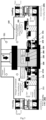
- the core component includes a low die bottom plate 210, a lower die holder 220, a lower die insert 230, an upper die top plate 240, an upper die holder 250, an upper die insert 260, a progressive die 270, a side pushing sealing oil cylinder module 280, and an electrode compression cylinder module 290.
- the lower die holder 220, the lower die insert 230, the progressive die 270, the upper die insert 260, the upper die holder 250, and the upper die top plate 240 are arranged on the lower die bottom plate 210 from top to bottom.
- the progressive die 270 includes a heating station 2B and a hot gas bulging and quenching station 2C.
- the die assembly 200 combines two operations of hot gas bulging and quenching forming, which greatly shortens processing time and avoids surface oxidation of products.
- the electrode compression cylinder module 290 includes an electrode compression cylinder
- the side pushing sealing oil cylinder module 280 includes a side pushing sealing oil cylinder 281 and a side pushing sealing head 282.
- the progressive die 270 includes a feeding bottom plate 271, a feeding module 272, and a feeding pallet 273.
- the feeding module 272 has a variety of driving functions, which can drive the feeding bottom plate 271 to translate from side to side and also drive the feeding pallet 273 to move up and down, and can also compress the workpieces W.
- the feeding module 272 includes progressive die drives 2721, a progressive die drive guide bar 2722, lifting hydraulic cylinders 2723, rotatable compression cylinders 2724 and rotatable pressure plates 2725.
- the feeding pallet 273 is provided with a plurality of die cavities 2731 for accommodating ends of the workpieces W, and a plurality of hole slots 2732 for accommodating the rotatable compression cylinders 2724.
- Each die cavity 2731 corresponds to a different processing station, such as the feeding station 2A, the heating station 2B, the hot gas bulging and quenching station 2C, and the unloading and heat preservation station 2D.
- the feeding pallet 273 is also provided with guide post 2733 for positioning.
- the lifting hydraulic cylinders 2723 can push the feeding pallet 273 to stop at multiple heights, such as a lower limit positon at the lowest position, a joint position at a middle position, and an upper limit position for lifting the workpieces to enter into next station.
- the progressive die drive 2721 includes a drive motor 27211, a reducer 27212, a gear 27213, and a rack 27214.
- the drive motor 27211 is fixedly arranged on the lower die bottom plate 210, and the gear 27213 is connected to the drive motor 27211 through the reducer 27212 and engaged with the rack 27214, the rack 27214 is arranged on the feeding bottom plate 271, which forms a gear and rack transmission system.
- the progressive die drive guide bar 2722 is fixedly arranged on the lower die bottom plate 210 and cooperates with the lower die holder 220 to guide translation of the feeding bottom plate 271.
- the feeding bottom plate 271 is driven by the gear and rack transmission system formed by the gear 27213 and the rack 27214, to translate from side to side on the bottom die bottom plate 210.
- the automatic loading and unloading modules include a ferry loading trolley 201, a ferry unloading trolley 202, a ferry loading and turning manipulator 203, and a ferry unloading and turning manipulator 204.
- the ferry loading trolley 201, the ferry loading and turning manipulator 203, the core component, the ferry unloading and turning manipulator 204 and the ferry unloading trolley 202 are sequentially arranged on the lower die bottom plate 210 from left to right.
- the ferry loading trolley 201 and the ferry unloading trolley 202 have the same structure, and both include a linear drive 2021, jacking cylinders 2022, a trolley pallet 2023, and a workpiece clamping plate 2024.
- the linear drive 2021 is configured to drive the trolley to move left and right along the guide rail 211 on the lower die bottom plate 210.
- the jacking cylinders 2022 are used to lift the trolley pallet2023.
- the workpiece clamping plate 2024 is arranged on the trolley pallet 2023 for clamping the workpiece W.
- the ferry loading and turning manipulator 203 and the ferry unloading and turning manipulator 204 have the same structure, and both include a linear drive 2041, a rotatable drive 2042, a rotatable mechanical arm 2043, and a clamping gripper 2044.
- the linear drive 2041 is used for driving the trolley to move left and right along the guide rails 211 on the lower die bottom plate 210.
- the rotatable drive 2042 is used to turn the rotatable mechanical arm 2043 so that the workpieces W can be turned 90 degrees or 180 degrees from bottom to top.
- the clamping gripper 2044 is used to grab the workpieces W.
- the rapid heating module 300 includes a direct current power supply 310 and conductive clamping blocks 320. Two conductive clamping blocks 320 are respectively clamped at the two ends of the workpiece W. After the circuit is turned on, the direct current power supply 310 rapidly heats a middle part of the workpiece except for the two ends thereof, by means of resistance heating.
- the rapid heating module 300 includes a direct current power supply 310, conductive compression blocks 330, insulating clamping blocks 340, and electrode compression cylinders 350.
- Two conductive compression blocks 330 are respectively pressed against the two ends of the workpiece W tightly, and each conductive compression block 330 is pressed by one electrode compression cylinder 350 so that the electrode is in close contact with the end of the workpiece W.
- the two ends of the workpiece W are supported by the insulating clamping blocks 340.
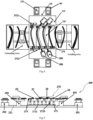
- the rapid cooling module 400 includes an upper die inlet water channel 410, an upper die annular cooling water channel 420, an upper die outlet water channel 430, and further includes a lower die inlet water channel 440, a lower die annular cooling water channel 450, and a lower die outlet water channel 460.
- the water channels 460 are separated from the workpiece W by an upper die insert 260 or a lower die insert 230.
- the upper die annular cooling water channel 420 is formed by a gap formed between the upper die insert 260 and the die insert 470
- the lower die annular cooling water channel 450 is formed by a gap formed between the lower die insert 230 and the die insert 470.
- a plurality of the upper die annular cooling water channel 420 and the lower die annular cooling water channel 450 are provided.
- a distance D between each upper die annular cooling water channel 420 and a lower surface of the upper die insert 260 is equal, and a distance between the lower die annular cooling water channel 450 and an upper surface of the lower die insert 230 is equal.
- a distance between the upper die annular cooling water channel 420 and a profile of the workpiece W is equal to a distance between the lower die annular cooling water channel 450 and the profile of the workpiece W, which facilitates uniform cooling of the workpiece.
- a plurality of parallel deep grooves 261 are milled on the upper die insert 260.
- Each deep groove 261 is filled with the die insert 470, and a gap between the die insert 470 and the upper die insert 260 forms one upper die annular cooling water channel 420.
- each deep groove is filled with the die insert 470, and a gap between each die insert 470 and the lower die insert 230 forms one lower die annular cooling water channel 450.
- the safety protection and sealing module 500 includes a loading transition sealing gas chamber 510, a safety protection and sealing compartment 520 and an unloading transition sealing gas chamber 530.
- the loading transition sealing gas chamber 510 and the unloading transition sealing gas chamber 530 are arranged on two sides of the safety protection and sealing compartment 520 respectively.
- the safety protection and sealing module 500 covers the die assembly 200 therein to form a positive pressure sealing environment.
- the safety protection and sealing module 500 can provide a positive pressure and sealed environment for the hot gas bulging and rapid cooling strengthening process for metal pipes, thereby avoiding product surface oxidation.
- the safety protection and sealing module 500 is made of thick steel plates which are provided around the die assembly 200 and over upper and lower surfaces thereof. A bottom surface of the safety protection and sealing module 500 is installed centrally on the moving table 120 of the hydraulic press, and the lower die bottom plate 210 of the die is installed on a lower steel plate of the safety protection and sealing module 500.
- the safety protection and sealing module 500 is provided with a sealing hole 540 in the thick steel plate.
- the sealing hole 540 is matched with the main cylinder piston rod 161 of the hydraulic press 100, the die flange guide rod 180 or the adapting rod 191 according to a Pneumatic seal standard, and a Pneumatic seal ring (not shown) is installed within the sealing hole 540.
- FIG. 17 it is a schematic diagram showing states where the workpiece W enters and exits the safety protection and sealing module 500. Viewed from left to right, it is an unloading process of the unloading transition sealing gas chamber 530, and viewed from right to left, it is a loading process of the loading transition sealing gas chamber 510. Taking the view from left to right as an example, the workpiece W is clamped by the ferry unloading and turning manipulator 204 at the heat preservation station 2D to the trolley pallet 2023 of the ferry unloading trolley 202.
- the ferry unloading trolley 202 travels to be directly below the unloading transition sealing gas chamber 530, and then raised, so that the pallet 2023 abuts a lower part of the unloading transition sealing gas chamber 530 to form a close contact therebetween, thereby preventing gas leakage. Then an upper cover plate 531 of the unloading transition sealing gas chamber 530 is lifted, and the workpiece W leaves the unloading transition sealing gas chamber 530, and can be taken away by the manipulator or a worker.
- several sealing rings (532, 533) are added at a position where the unloading transition sealing gas chamber 530 contacts the trolley pallet 2023.
- the loading transition sealing gas chamber 510 has the same structure as the unloading transition sealing gas chamber 530.
- the loading transition sealing gas chamber 510 includes a material inlet and the upper cover plate 531, and the material inlet is arranged on an upper part of the safety protection and sealing compartment 520.
- the unloading transition sealing gas chamber 530 includes a material outlet 534 and the upper cover plate 531.
- the material outlet 534 is arranged on the upper part of the safety protection and sealing compartment 520.
- the material inlet and the material outlet 534 are respectively arranged on two sides of the safety protection and sealing compartment 520.
- the upper cover plate 531 can completely cover the material inlet and the material outlet 534.
- Two parallel flanges 5311 are provided at a lower part of the upper cover plate 531, and a distance between the two flanges 5311 is the same as an opening width of the material inlet and the material outlet 534
- a first sealing ring 532 is provided on a side wall of the material inlet or the material outlet 534 to form a sealing engagement with the workpiece clamping plate configured for transporting the workpiece W.
- a second sealing ring 533 is provided on the upper surface of the material inlet or the material outlet 534, so as to to form a sealing engagement with the flanges 5311 of the upper cover plate 531.
- a pressure relief hole 521 is provided on the safety protection and sealing compartment 520.
- Multiple pressure relief holes 521 are provided, which can automatically burst when the pressure in the safety protection and sealing compartment 520 is too high, so as to relieve the pressure in the safety protection and sealing compartment 520.
- a pressure relief film 522 is provided on an inner side wall of the safety protection and sealing compartment 520 where the pressure relief hole 521 is provided, and is fixed by a fastener 525 such as a screw.
- a third sealing ring 524 is provided between the pressure relief film 522 and the inner side wall of the safety protection and sealing compartment 520 to prevent gas leakage.
- other forms of safety means can also be arranged in the safety protection and sealing compartment 520.
- a pressure valve similar to a pressure cooker is arranged on the safety protection and sealing compartment 520, and the valve can release pressure when the pressure valve is lifted; or a spring is arranged in the pressure valve, the spring is lifted when the pressure exceeds a predetermined value, the pressure valve releases the pressure.
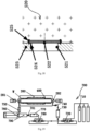
- the ultra-high pressure gas circulation control module 700 includes a nitrogen tank assembly 710, a first two-way booster 720, a high-pressure gas storage tank 730, an inflation valve 740, a gas cooler 750, a rapid boosting oil cylinder 760, and a low-pressure gas storage tank 770 and a second two-way booster 780.
- the first two-way booster 720 is respectively connected to the nitrogen tank assembly 710, the high-pressure gas storage tank 730 and the second two-way booster 780, the high-pressure gas storage tank 730 is connected with the inflation valve 740.
- the gas cooler 750 is connected to the rapid boosting oil cylinder 760, the rapid boosting oil cylinder 760 is connected to the low-pressure gas storage tank 770, and the low-pressure gas storage tank 770 is connected to the second two-way booster 780.
- the rapid boosting oil cylinder 760 has a low pressure cylinder cavity 790.
- a gas inlet end of the low pressure cylinder cavity 790 is connected to the gas cooler 750.
- the gas outlet end of the low pressure cylinder cavity 790 is connected with the second two-way booster 780 through a check valve 701.
- Ends of the inflation valve 740 and the gas cooler 750 are provided with high temperature solenoid valves for tightly connecting with a cavity port of the workpiece W, so that ultra-high pressure gas can be filled into a cavity of the workpiece W to achieve high temperature bulging.
- a volume of the low-pressure cylinder cavity 790 is usually 10-100 times larger than that of a target workpiece W, in order to fully absorb the high-pressure gas after the workpiece is formed, and reduce residual gas pressure inside the pipe workpiece W.
- the volume of the low-pressure cylinder cavity 790 can be larger if space is enough.
- the nitrogen tank assembly 710 can be replaced by an inert gas tank assembly or a CO 2 gas tank assembly.
- the first two-way booster 720 pressurizes low-pressure nitrogen in the gas storage tank assembly 710 into the high-pressure gas storage tank 730, and inflates the heated pipe workpiece W through the inflation valve 740. After the workpiece W is bulged and quenched, the gas in the pipe cavity is heated. The high-pressure hot gas is cooled by the gas cooler 750, and then released into the low-pressure cylinder cavity 790 of the rapid boosting oil cylinder 760 (an initial state therein is close to vacuum). When the gas pressure in the low-pressure cylinder cavity 790 is close to the gas pressure inside the pipe, the gas recovery is over.
- the residual gas in the pipe workpiece W can be released into the safety protection and sealing compartment 520 after the die is opened, which can be used for continuous supplementation of the protective gas environment pressure.
- the rapid boosting oil cylinder 760 quickly compresses the low-pressure nitrogen absorbed by the low-pressure cylinder cavity 790 into the low-pressure gas storage tank 770, and the rapid boosting oil cylinder 760 retracts to a final position after being pushed to the limit position (at this time, the pressure in the low-pressure cylinder cavity 790 is again return to a state close to the vacuum).
- the check valve 701 prevents the gas in the low-pressure gas storage tank 770 from returning to the low-pressure cylinder cavity 790.
- the second two-way booster 780 continues to pressurize the recovered gas in the low-pressure gas storage tank 770, the pressurized gas enters the high-pressure gas storage tank 730 through the first two-way booster 720, for subsequent bulging of the workpiece. This process is circulated.
- the ultra-high pressure gas circulation control module 700 overcomes the safety problem existing in ultra-high pressure gas pressure and high temperature heating equipment in the prior art.
- the present disclosure provides the hot gas bulging and rapid cooling strengthening process for metal pipes, including the following steps:
- nitrogen, carbon dioxide, or inert gas may be introduced into the die of the die assembly 200 to protect the workpiece W from oxidation.
- the die of the die assembly 200 is preferably a progressive die 270.
- the entire die assembly 200 is provided in a sealed environment created by the safety protection and sealing module 500
- step 2) there is a heat preservation step between step 2) and step 3).
- the quenched workpiece W enters the unloading heat preservation station 2D, and is kept at medium and low temperatures for a predetermined time to adjust strength and toughness of the parts.
- heating, bulging, rapid cooling strengthening and heat preservation of the workpiece W is completed on the die assembly 200.
- the quenching operation is performed by the rapid cooling module 400.
- the sealing environment is provided by the safety protection and sealing module 500.
- the ultra-high-pressure gas circulation control module 700 provides high-pressure gas to the die assembly 200.
- the present disclosure also provides a typical flow of the hot gas bulging and rapid cooling strengthening process for closed metal pipes, including the following steps:
Applications Claiming Priority (2)
| Application Number | Priority Date | Filing Date | Title |
|---|---|---|---|
| CN201910160324 | 2019-03-04 | ||
| PCT/CN2020/077674 WO2020177694A1 (zh) | 2019-03-04 | 2020-03-04 | 一种金属管材热态气体胀形与快冷强化系统及工艺 |
Publications (4)
| Publication Number | Publication Date |
|---|---|
| EP3919201A1 EP3919201A1 (en) | 2021-12-08 |
| EP3919201A4 EP3919201A4 (en) | 2023-03-22 |
| EP3919201C0 EP3919201C0 (en) | 2023-10-11 |
| EP3919201B1 true EP3919201B1 (en) | 2023-10-11 |
Family
ID=70781552
Family Applications (1)
| Application Number | Title | Priority Date | Filing Date |
|---|---|---|---|
| EP20767395.5A Active EP3919201B1 (en) | 2019-03-04 | 2020-03-04 | Hot metal gas forming and quenching system and process therefor |
Country Status (5)
| Country | Link |
|---|---|
| US (1) | US11752535B2 (zh) |
| EP (1) | EP3919201B1 (zh) |
| JP (1) | JP7244726B2 (zh) |
| CN (8) | CN212042201U (zh) |
| WO (2) | WO2020177694A1 (zh) |
Families Citing this family (19)
| Publication number | Priority date | Publication date | Assignee | Title |
|---|---|---|---|---|
| CN212042201U (zh) * | 2019-03-04 | 2020-12-01 | 航宇智造(北京)工程技术有限公司 | 金属管材胀形与快冷强化工艺用的安全防护与密封模块 |
| JP7448396B2 (ja) * | 2020-03-27 | 2024-03-12 | 住友重機械工業株式会社 | 成形システム |
| CN112474957A (zh) * | 2020-09-08 | 2021-03-12 | 上海凌云工业科技有限公司凌云汽车技术分公司 | 一种热冲压柔性smart生产线 |
| CN112775318B (zh) * | 2020-11-11 | 2022-11-25 | 珠海华星智能技术有限公司 | 一种用于空调翅片换热器铜管的气压胀管方法 |
| CN114472666A (zh) * | 2020-11-13 | 2022-05-13 | 上海宝钢高新技术零部件有限公司 | 一种管状液压成形前翼子板支撑件的成形装置和方法 |
| CN112662862A (zh) * | 2020-12-23 | 2021-04-16 | 上海天阳钢管有限公司 | 一种双金属复合管热处理装置及热处理工艺方法 |
| CN112792280A (zh) * | 2020-12-31 | 2021-05-14 | 林州重机铸锻有限公司 | 导向套热镦机及其热镦方法 |
| CN112916710A (zh) * | 2021-01-23 | 2021-06-08 | 广东思豪内高压科技有限公司 | 一种不锈钢管件的内高压成型控制系统 |
| CN113715367B (zh) * | 2021-07-16 | 2022-08-09 | 北京科技大学 | 一种管梁零件制备工艺及管梁零件 |
| CN113857326B (zh) * | 2021-09-17 | 2024-01-09 | 北京航星机器制造有限公司 | 一种高温真空条件下管件多向成形装置及制备方法 |
| CN114345271A (zh) * | 2021-12-22 | 2022-04-15 | 陈健 | 一种多联化学合成反应器 |
| CN114273490B (zh) * | 2021-12-27 | 2024-01-23 | 仪征常众汽车部件有限公司 | 基于热冲压方式的汽车保险杠快速冷却成型装置 |
| CN114453503B (zh) * | 2021-12-29 | 2023-11-14 | 江苏铠杰轻合金材料有限公司 | 曲铝板在线整形装置 |
| CN114438302B (zh) * | 2022-02-08 | 2024-01-05 | 山东正阳机械股份有限公司 | 一种新型全自动高频淬火炉 |
| CN114505392A (zh) * | 2022-03-09 | 2022-05-17 | 嵊州天脉导热科技有限公司 | 用于均热板上盖板的高稳定成型设备 |
| CN114932172B (zh) * | 2022-06-17 | 2024-03-29 | 燕山大学 | 一种双金属复合管生产装置及其方法 |
| CN116020948B (zh) * | 2023-03-29 | 2023-06-23 | 常州希米智能科技有限公司 | 一种基于冲压模具的配套降温冷却机构 |
| CN116590512B (zh) * | 2023-05-31 | 2024-01-30 | 金华克钻特钢工具有限公司 | 一种拉刀的真空淬火炉 |
| KR102588591B1 (ko) * | 2023-09-08 | 2023-10-16 | 디에이치 주식회사 | 전고체전지 제조공정 중 노칭공정에서의 프레스 세정장치 |
Citations (2)
| Publication number | Priority date | Publication date | Assignee | Title |
|---|---|---|---|---|
| EP0588528A1 (en) * | 1992-09-15 | 1994-03-23 | Aquaform Inc | Apparatus and method for forming and hydropiercing a tubular frame member |
| US20080307848A1 (en) * | 2006-12-22 | 2008-12-18 | Honda Motor Co., Ltd. | Bulging Method and Apparatus |
Family Cites Families (28)
| Publication number | Priority date | Publication date | Assignee | Title |
|---|---|---|---|---|
| US3998087A (en) * | 1975-10-30 | 1976-12-21 | Gulf & Western Manufacturing Company | Press slide with extendable and retractable tool support |
| DE3245317A1 (de) * | 1982-12-08 | 1984-06-14 | Eumuco Aktiengesellschaft für Maschinenbau, 5090 Leverkusen | Hubbalkenmanipulator fuer gesenkschmiedepressen u. dgl. |
| JPS61169121A (ja) * | 1985-01-22 | 1986-07-30 | Ishikawajima Harima Heavy Ind Co Ltd | プレスにおけるタ−ンオ−バ−装置 |
| US5353618A (en) * | 1989-08-24 | 1994-10-11 | Armco Steel Company, L.P. | Apparatus and method for forming a tubular frame member |
| US6322645B1 (en) | 1999-09-24 | 2001-11-27 | William C. Dykstra | Method of forming a tubular blank into a structural component and die therefor |
| US7024897B2 (en) * | 1999-09-24 | 2006-04-11 | Hot Metal Gas Forming Intellectual Property, Inc. | Method of forming a tubular blank into a structural component and die therefor |
| JP3761820B2 (ja) | 2001-09-04 | 2006-03-29 | アイシン高丘株式会社 | 金属部材成形方法 |
| US7047615B2 (en) * | 2002-05-06 | 2006-05-23 | Norek Richard S | Forming gas turbine transition duct bodies without longitudinal welds |
| CN201265996Y (zh) * | 2008-09-05 | 2009-07-01 | 苏州制氧机有限责任公司 | 双膨胀机中压液化设备 |
| CN101507995B (zh) * | 2009-03-11 | 2010-08-18 | 上海龙川塑料制品有限公司 | 一种在多工位传递连续模上的液压涨型模具 |
| DE102009030089B3 (de) * | 2009-06-22 | 2010-11-11 | Benteler Automobiltechnik Gmbh | Verfahren zur Innenhochdruckumformung |
| CN101912919B (zh) * | 2010-07-16 | 2012-04-25 | 沈阳黎明航空发动机(集团)有限责任公司 | 一种气胀成形和热成形复合成形方法及其采用的装置 |
| KR101326824B1 (ko) | 2011-11-07 | 2013-11-11 | 현대자동차주식회사 | 핫 스탬핑 성형용 금형 |
| EP2800360B1 (en) | 2011-12-27 | 2019-11-27 | Saturn Licensing LLC | Connecting device |
| JP6381967B2 (ja) | 2014-05-22 | 2018-08-29 | 住友重機械工業株式会社 | 成形装置及び成形方法 |
| JP6475437B2 (ja) | 2014-08-05 | 2019-02-27 | 住友重機械工業株式会社 | 成形装置 |
| CN104438541A (zh) * | 2014-12-08 | 2015-03-25 | 无锡朗贤汽车组件研发中心有限公司 | 管件气胀热成形生产设备 |
| US9433992B1 (en) * | 2015-03-31 | 2016-09-06 | The Boeing Company | Bulge forming apparatus and method |
| JP6309480B2 (ja) | 2015-03-31 | 2018-04-11 | 住友重機械工業株式会社 | 成形装置 |
| CN107614563B (zh) | 2015-05-22 | 2020-08-11 | 日立化成株式会社 | 环氧树脂组合物、导热材料前体、b阶片、预浸渍体、散热材料、层叠板、金属基板和印刷配线板 |
| CN106077284B (zh) * | 2016-06-14 | 2019-01-15 | 芜湖同创模具机械有限公司 | 一种自动上下料的压型模具的自动控制系统 |
| JP6763606B2 (ja) * | 2016-09-23 | 2020-09-30 | 株式会社富士機械工作所 | バルジ成形装置及びバルジ成形方法 |
| CA3049630A1 (en) * | 2017-03-30 | 2018-10-04 | Sumitomo Heavy Industries, Ltd. | Forming system |
| CN107052127B (zh) * | 2017-06-12 | 2019-03-01 | 东营布鲁特新材料有限公司 | 一种高温气胀成形生产线系统及方法 |
| CN107570614A (zh) * | 2017-10-10 | 2018-01-12 | 常州常发制冷科技有限公司 | 水压胀管装置 |
| CN207887757U (zh) * | 2018-02-01 | 2018-09-21 | 惠州市诚业家具有限公司 | 缩口机构以及设有缩口机构的金属管加工设备 |
| CN108585451A (zh) | 2018-02-06 | 2018-09-28 | 惠州纽卡沃科技有限公司 | 一种降低热弯玻璃模具损耗的方法及其设备 |
| CN212042201U (zh) * | 2019-03-04 | 2020-12-01 | 航宇智造(北京)工程技术有限公司 | 金属管材胀形与快冷强化工艺用的安全防护与密封模块 |
-
2020
- 2020-03-04 CN CN202020247450.1U patent/CN212042201U/zh active Active
- 2020-03-04 CN CN202020247448.4U patent/CN211757877U/zh active Active
- 2020-03-04 CN CN202010141225.4A patent/CN111203469B/zh active Active
- 2020-03-04 CN CN202020247473.2U patent/CN212042202U/zh active Active
- 2020-03-04 CN CN202020247449.9U patent/CN212042200U/zh active Active
- 2020-03-04 US US17/434,618 patent/US11752535B2/en active Active
- 2020-03-04 CN CN202010141237.7A patent/CN111203467B/zh active Active
- 2020-03-04 WO PCT/CN2020/077674 patent/WO2020177694A1/zh unknown
- 2020-03-04 CN CN202020247430.4U patent/CN211758113U/zh active Active
- 2020-03-04 WO PCT/CN2020/077675 patent/WO2020177695A1/zh active Application Filing
- 2020-03-04 EP EP20767395.5A patent/EP3919201B1/en active Active
- 2020-03-04 CN CN202020247461.XU patent/CN211757876U/zh active Active
- 2020-03-04 JP JP2021551879A patent/JP7244726B2/ja active Active
Patent Citations (2)
| Publication number | Priority date | Publication date | Assignee | Title |
|---|---|---|---|---|
| EP0588528A1 (en) * | 1992-09-15 | 1994-03-23 | Aquaform Inc | Apparatus and method for forming and hydropiercing a tubular frame member |
| US20080307848A1 (en) * | 2006-12-22 | 2008-12-18 | Honda Motor Co., Ltd. | Bulging Method and Apparatus |
Also Published As
| Publication number | Publication date |
|---|---|
| WO2020177695A1 (zh) | 2020-09-10 |
| CN111203469A (zh) | 2020-05-29 |
| CN211757877U (zh) | 2020-10-27 |
| CN111203467B (zh) | 2021-07-27 |
| CN211758113U (zh) | 2020-10-27 |
| CN212042200U (zh) | 2020-12-01 |
| EP3919201A1 (en) | 2021-12-08 |
| EP3919201C0 (en) | 2023-10-11 |
| CN211757876U (zh) | 2020-10-27 |
| CN212042202U (zh) | 2020-12-01 |
| US11752535B2 (en) | 2023-09-12 |
| EP3919201A4 (en) | 2023-03-22 |
| JP7244726B2 (ja) | 2023-03-23 |
| US20220168792A1 (en) | 2022-06-02 |
| CN212042201U (zh) | 2020-12-01 |
| WO2020177694A1 (zh) | 2020-09-10 |
| CN111203467A (zh) | 2020-05-29 |
| JP2022522308A (ja) | 2022-04-15 |
| CN111203469B (zh) | 2022-06-28 |
Similar Documents
| Publication | Publication Date | Title |
|---|---|---|
| EP3919201B1 (en) | Hot metal gas forming and quenching system and process therefor | |
| CN105234232B (zh) | 一种汽车后备门包边专用模具 | |
| EP1638713A1 (en) | Hydroforming apparatus with stacked dies | |
| CN104525675A (zh) | 硼钢钢管的气胀热成形工艺 | |
| US7661283B2 (en) | Bulging method and apparatus | |
| CN116159959A (zh) | 一种法兰锻造平台及其锻造方法 | |
| CN101486062B (zh) | 高强度钢零件的热成形和切边一体化工艺及模具 | |
| CN216065071U (zh) | 一种钢管热气胀成形工艺系统 | |
| EP2176012B1 (en) | Method and system for upsetting hollow members | |
| CN216385115U (zh) | 一种双工器罩体加工用热处理炉 | |
| CN108160797B (zh) | 一种敞口管件气胀热成型模具及工艺 | |
| CN116967674B (zh) | 片式散热器封板、法兰焊接设备及片式散热器焊接生产线 | |
| CN108161353A (zh) | 一种性能均匀的大型铝合金拼焊板封头整体成形的方法 | |
| KR102626343B1 (ko) | 대면적 소재용 초소성 성형장치 | |
| CN117619982A (zh) | 高速动车组前端铝合金开闭机构舱门、成形模具及方法 | |
| CN111496059A (zh) | 一种柔性横梁式油缸锁紧管件或型材液压成形工艺 | |
| CN117019983A (zh) | 一种功能一体化金属管成型模具及其使用方法 | |
| CN114273513A (zh) | 一种用于制造封闭截面扭力梁的装置及其制造方法 | |
| CN111434408A (zh) | 一种柔性横梁式螺旋锁紧管件或型材液压成形工艺 | |
| CN116833291A (zh) | 一种钛合金回转体零件热成形装置 | |
| CN112391514A (zh) | 一种薄壁密封桶型淬火排气装置 | |
| CN117340115A (zh) | 一种超高强度封闭截面a柱的制造方法及装置 | |
| CN111434413A (zh) | 一种柔性横梁式螺旋锁紧板件液压成形工艺 | |
| JP2011240381A (ja) | ハイドロフォーム成形品の製造装置および製造方法 |
Legal Events
| Date | Code | Title | Description |
|---|---|---|---|
| STAA | Information on the status of an ep patent application or granted ep patent |
Free format text: STATUS: THE INTERNATIONAL PUBLICATION HAS BEEN MADE |
|
| PUAI | Public reference made under article 153(3) epc to a published international application that has entered the european phase |
Free format text: ORIGINAL CODE: 0009012 |
|
| STAA | Information on the status of an ep patent application or granted ep patent |
Free format text: STATUS: REQUEST FOR EXAMINATION WAS MADE |
|
| 17P | Request for examination filed |
Effective date: 20210902 |
|
| AK | Designated contracting states |
Kind code of ref document: A1 Designated state(s): AL AT BE BG CH CY CZ DE DK EE ES FI FR GB GR HR HU IE IS IT LI LT LU LV MC MK MT NL NO PL PT RO RS SE SI SK SM TR |
|
| DAV | Request for validation of the european patent (deleted) | ||
| DAX | Request for extension of the european patent (deleted) | ||
| RIC1 | Information provided on ipc code assigned before grant |
Ipc: B21D 43/13 20060101ALN20221005BHEP Ipc: B21D 43/02 20060101ALN20221005BHEP Ipc: C21D 9/48 20060101ALI20221005BHEP Ipc: C21D 9/00 20060101ALI20221005BHEP Ipc: C21D 7/13 20060101ALI20221005BHEP Ipc: C21D 1/74 20060101ALI20221005BHEP Ipc: C21D 1/673 20060101ALI20221005BHEP Ipc: C21D 1/40 20060101ALI20221005BHEP Ipc: C21D 1/18 20060101ALI20221005BHEP Ipc: B21D 37/16 20060101ALI20221005BHEP Ipc: B21D 26/047 20110101ALI20221005BHEP Ipc: B21D 26/041 20110101ALI20221005BHEP Ipc: B21D 26/033 20110101AFI20221005BHEP |
|
| A4 | Supplementary search report drawn up and despatched |
Effective date: 20230222 |
|
| RIC1 | Information provided on ipc code assigned before grant |
Ipc: B21D 43/13 20060101ALN20230216BHEP Ipc: B21D 43/02 20060101ALN20230216BHEP Ipc: C21D 9/48 20060101ALI20230216BHEP Ipc: C21D 9/00 20060101ALI20230216BHEP Ipc: C21D 7/13 20060101ALI20230216BHEP Ipc: C21D 1/74 20060101ALI20230216BHEP Ipc: C21D 1/673 20060101ALI20230216BHEP Ipc: C21D 1/40 20060101ALI20230216BHEP Ipc: C21D 1/18 20060101ALI20230216BHEP Ipc: B21D 37/16 20060101ALI20230216BHEP Ipc: B21D 26/047 20110101ALI20230216BHEP Ipc: B21D 26/041 20110101ALI20230216BHEP Ipc: B21D 26/033 20110101AFI20230216BHEP |
|
| GRAP | Despatch of communication of intention to grant a patent |
Free format text: ORIGINAL CODE: EPIDOSNIGR1 |
|
| STAA | Information on the status of an ep patent application or granted ep patent |
Free format text: STATUS: GRANT OF PATENT IS INTENDED |
|
| RIC1 | Information provided on ipc code assigned before grant |
Ipc: B21D 43/13 20060101ALN20230628BHEP Ipc: B21D 43/02 20060101ALN20230628BHEP Ipc: C21D 9/48 20060101ALI20230628BHEP Ipc: C21D 9/00 20060101ALI20230628BHEP Ipc: C21D 7/13 20060101ALI20230628BHEP Ipc: C21D 1/74 20060101ALI20230628BHEP Ipc: C21D 1/673 20060101ALI20230628BHEP Ipc: C21D 1/40 20060101ALI20230628BHEP Ipc: C21D 1/18 20060101ALI20230628BHEP Ipc: B21D 37/16 20060101ALI20230628BHEP Ipc: B21D 26/047 20110101ALI20230628BHEP Ipc: B21D 26/041 20110101ALI20230628BHEP Ipc: B21D 26/033 20110101AFI20230628BHEP |
|
| INTG | Intention to grant announced |
Effective date: 20230713 |
|
| GRAS | Grant fee paid |
Free format text: ORIGINAL CODE: EPIDOSNIGR3 |
|
| GRAA | (expected) grant |
Free format text: ORIGINAL CODE: 0009210 |
|
| STAA | Information on the status of an ep patent application or granted ep patent |
Free format text: STATUS: THE PATENT HAS BEEN GRANTED |
|
| AK | Designated contracting states |
Kind code of ref document: B1 Designated state(s): AL AT BE BG CH CY CZ DE DK EE ES FI FR GB GR HR HU IE IS IT LI LT LU LV MC MK MT NL NO PL PT RO RS SE SI SK SM TR |
|
| REG | Reference to a national code |
Ref country code: GB Ref legal event code: FG4D |
|
| REG | Reference to a national code |
Ref country code: CH Ref legal event code: EP |
|
| REG | Reference to a national code |
Ref country code: DE Ref legal event code: R096 Ref document number: 602020019152 Country of ref document: DE |
|
| REG | Reference to a national code |
Ref country code: IE Ref legal event code: FG4D |
|
| U01 | Request for unitary effect filed |
Effective date: 20231031 |
|
| U07 | Unitary effect registered |
Designated state(s): AT BE BG DE DK EE FI FR IT LT LU LV MT NL PT SE SI Effective date: 20231103 |
|
| U20 | Renewal fee paid [unitary effect] |
Year of fee payment: 5 Effective date: 20240229 |
|
| PG25 | Lapsed in a contracting state [announced via postgrant information from national office to epo] |
Ref country code: GR Free format text: LAPSE BECAUSE OF FAILURE TO SUBMIT A TRANSLATION OF THE DESCRIPTION OR TO PAY THE FEE WITHIN THE PRESCRIBED TIME-LIMIT Effective date: 20240112 |
|
| PG25 | Lapsed in a contracting state [announced via postgrant information from national office to epo] |
Ref country code: IS Free format text: LAPSE BECAUSE OF FAILURE TO SUBMIT A TRANSLATION OF THE DESCRIPTION OR TO PAY THE FEE WITHIN THE PRESCRIBED TIME-LIMIT Effective date: 20240211 |