EP3914552B1 - Véhicule d'entrepôt doté d'un entraînement à chenilles - Google Patents
Véhicule d'entrepôt doté d'un entraînement à chenilles Download PDFInfo
- Publication number
- EP3914552B1 EP3914552B1 EP21701950.4A EP21701950A EP3914552B1 EP 3914552 B1 EP3914552 B1 EP 3914552B1 EP 21701950 A EP21701950 A EP 21701950A EP 3914552 B1 EP3914552 B1 EP 3914552B1
- Authority
- EP
- European Patent Office
- Prior art keywords
- drive
- warehouse vehicle
- guide rail
- warehouse
- belt
- Prior art date
- Legal status (The legal status is an assumption and is not a legal conclusion. Google has not performed a legal analysis and makes no representation as to the accuracy of the status listed.)
- Active
Links
Images


Classifications
-
- B—PERFORMING OPERATIONS; TRANSPORTING
- B66—HOISTING; LIFTING; HAULING
- B66F—HOISTING, LIFTING, HAULING OR PUSHING, NOT OTHERWISE PROVIDED FOR, e.g. DEVICES WHICH APPLY A LIFTING OR PUSHING FORCE DIRECTLY TO THE SURFACE OF A LOAD
- B66F9/00—Devices for lifting or lowering bulky or heavy goods for loading or unloading purposes
- B66F9/06—Devices for lifting or lowering bulky or heavy goods for loading or unloading purposes movable, with their loads, on wheels or the like, e.g. fork-lift trucks
- B66F9/07—Floor-to-roof stacking devices, e.g. "stacker cranes", "retrievers"
- B66F9/072—Travelling gear therefor
-
- B—PERFORMING OPERATIONS; TRANSPORTING
- B61—RAILWAYS
- B61C—LOCOMOTIVES; MOTOR RAILCARS
- B61C11/00—Locomotives or motor railcars characterised by the type of means applying the tractive effort; Arrangement or disposition of running gear other than normal driving wheel
- B61C11/04—Locomotives or motor railcars characterised by the type of means applying the tractive effort; Arrangement or disposition of running gear other than normal driving wheel tractive effort applied to racks
Definitions
- the invention relates to a drive for vehicles that are used in warehouses, such as storage and retrieval devices for storing and retrieving articles in/from storage racks.
- Such storage and retrieval devices take over, for example, the loading and unloading of goods from a high-bay warehouse.
- the storage and retrieval device drives to the respective storage locations in the rack storage and removes or loads the respective goods.
- the performance, i.e. the goods throughput of such a rack storage system depends critically on the speed and in particular the possible maximum acceleration of the stacker cranes or other storage vehicles. This places high demands on the drive technology of the warehouse vehicles, especially for vehicles with a high dead weight or high payload.
- the present invention is therefore based on the object of proposing a drive concept for a storage vehicle that enables high acceleration and deceleration values while at the same time requiring little maintenance and assembly work for the drive elements.
- the object is achieved by the storage vehicle described in claim 1 according to the invention, which can be moved along a guide rail provided with engagement elements and has a chassis and a drive unit connected to the chassis.
- the drive unit has a drive wheel coupled to a drive motor with engagement elements on the circumference, an endless drive belt provided with engagement elements, and a steering roller arrangement for guiding the endless drive belt, which is designed in such a way that the endless drive belt for driving the storage vehicle can be connected to both the drive wheel and the drive wheel as well as being engageable with the engaging elements of the guide rail.
- the engagement elements or teeth of the endless drive belt engage the engagement elements of the guide rail over a greater distance, as do the engagement elements of the drive wheel with those of the endless drive belt.
- the driving force is therefore distributed to a plurality of pairs of engaging elements, respectively.
- the drive according to the invention thus enables high acceleration and deceleration values in both directions of movement, even with heavy loads, and thus high performance of the storage vehicle with low maintenance costs and low noise development at the same time.
- the endless drive belt is routed in an omega geometry around the drive wheel and caster wheel assembly such that the engagement elements on the same side of the endless drive belt engage both the drive wheel and the guide rail provided with engagement elements.
- the omega geometry enables a "compact" construction of the drive.
- the guide roller arrangement preferably comprises two deflection rollers on the guide rail side and two deflection rollers facing away from the guide rail, it being possible for one or more of the deflection rollers to be designed as a tensioning roller for tensioning the endless drive belt.
- the drive unit can have pressure elements, preferably pressure rollers, for pressing the endless drive belt against the guide rail provided with engagement elements.
- the endless drive belt can be made of elastic material such as plastic or rubber material, preferably made of polyurethane.
- the use of an NFC fabric can further reduce the noise development.
- the storage vehicle preferably has guide rollers to maintain a defined distance between the drive unit and the guide rail.
- the drive unit can have one or more drive motors, which is/are coupled to the axle of the drive wheel via a belt drive.
- the belt drive can have a step-up or step-down and can thus serve as a gear.
- a gear flanged to the drive motor can be dispensed with, as a result of which a considerable weight can be saved.
- the drive motor can be arranged separately from the drive unit.
- the chassis of the storage vehicle preferably has a chassis body and one or more running wheels.
- the invention further relates to a storage vehicle system having a guide rail provided with engagement elements and a storage vehicle according to the invention that can be moved along the guide rail.
- the engagement elements of the guide rail can be formed by toothed belts attached to it.
- the toothed belts can be made of elastic material, preferably made of polyurethane. NFC fabric can also be used here to reduce noise.
- the toothed belts are preferably fixed to the guide rail at certain intervals.
- the invention also relates to warehouses which have one or more warehouse vehicle systems according to the invention, the guide rails being arranged in the longitudinal and/or transverse direction or also in the vertical direction corresponding to a direction of movement of the respective warehouse vehicle.
- Figures 1-4 show a first embodiment of the storage vehicle according to the invention.
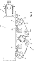
- Figure 1A shows a schematic perspective view of the chassis 50 of the embodiment of a storage vehicle according to the invention.
- the warehouse vehicle can perform any functions within a warehouse and have corresponding structures and handling elements that are not shown here and are independent of the invention.
- the storage vehicle can be used as a shelf vehicle for loading and unloading goods from a high-bay warehouse or as a cross conveyor for connecting different conveyor technology elements such as roller or belt conveyors.
- the invention relates to the drive of the storage vehicle, which storage vehicle can fulfill a wide variety of functions.
- wheel carrier which include wheels 30. These are used to guide the warehouse vehicle through the aisle. However, other wheel arrangements are also possible.
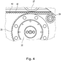
- the guide rail 40 is also shown, which is arranged in a stationary manner in the storage building and defines the route of the storage vehicle. As in particular in the detailed representations of Figures 1B and 1C can be seen, is on the guide rail 40 with a toothed belt 42 engagement elements (teeth) 43 (cf. 4 ) appropriate.
- the toothed belt 42 is preferably made of an elastic material such as a plastic or rubber material, in particular made of polyurethane, and is fixed at certain distances to the guide rail 40 and forms a fixed unit with it. This unit is preferably mounted over the entire length of the aisle/lane of the warehouse and can be fixed to the floor by means of a rail foot or the like.
- the toothed belt 42 fixed to a guide rail 40 has the further advantage of a significantly lower assembly effort, since several toothed rack elements mounted one behind the other must be aligned very precisely with one another, which means a high manufacturing effort. This effort does not apply when using a toothed belt.
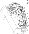
- FIG. 2 shows a schematic horizontal sectional view and 3 a perspective view of the drive unit 20, which accelerates and drives the storage vehicle on the track.
- the drive unit 20 accelerates and drives the storage vehicle on the track.
- a part of the chassis support 51 and one of the running wheels 30 is visible.
- the engagement elements (teeth) of an endless drive belt 25 engage in the toothed belt 42 21 is guided.
- the toothed side of the endless drive belt 25 is inserted into the toothed belt 42 .
- One or more deflection rollers are designed to be movable as tension roller(s) 24a for setting a suitable tension of the endless drive belt 25.
- the drive wheel 21 is coupled to an electric motor or another suitable drive unit. Due to the omega geometry, the engagement elements of the drive wheel 21 are in engagement with the engagement elements of the endless drive belt 25 over a significant part of the circumference of the drive wheel 21, so that good power transmission from the drive wheel 21 to the endless drive belt 25 is ensured with little maintenance .
- the drive unit 20 is preferably firmly connected to the chassis support 51 of the storage vehicle and can be detached from it by dismantling various components.
- a guide roller 27, in particular in the 3 and 4 is visible, the drive unit 20 is kept at a constant distance from the chassis beam 51, so that a good engagement of the engagement elements of the endless drive belt 25 in the corresponding engagement elements of the toothed belt 42 is possible.
- pressure rollers 28 are provided for the for Force transmission required contact pressure of the endless drive belt 25 on the toothed belt 42 provides. The power transmission from the endless drive belt 25 to the toothed belt 42 is distributed over a large number of pairs of engagement elements, so that the force and thus the wear on the individual engagement elements is reduced.
- noise-reducing materials such as polyurethane and NFC fabric can also be used for the drive wheel 21, the endless drive belt 25 and the toothed belt 42.
- the toothed belt 42 transmits the force via the guide rail 40 and the ground connection to the ground.
- the figures 5 and 6 show a second embodiment of the drive unit 20 of the storage vehicle according to the invention.
- the mode of operation of the second exemplary embodiment essentially corresponds to that of the first exemplary embodiment, but is characterized by a particularly compact design.
- figure 7 again shows a third exemplary embodiment of the drive unit 20 of the storage vehicle according to the invention, which is based on the second exemplary embodiment but differs from it in that two drive motors 60 are attached directly to the drive unit.
- the drive force is transmitted from the motors 60 to the drive shaft of the drive wheel 21 via belt drives 29 .
- a suitable transmission or reduction can be selected between the drive motors 60 and the drive wheel 21 by suitably selecting the diameter of the pulleys.
- the belt drive can also serve as a gear, which means that a heavy and bulky motor gear can be omitted.
- the warehouse vehicle according to the invention thus enables high accelerations and decelerations in both directions of movement, even with heavy loads, and thus an increase in the performance of the associated warehouse.
- the storage vehicle can be moved along the aisle of a rack warehouse or used as a cross conveyor at right angles to the direction of the aisle or to connect different conveyor technology elements such as roller or belt conveyors.
- the drive according to the invention can also be used to drive vertical conveyors.
Landscapes
- Engineering & Computer Science (AREA)
- Transportation (AREA)
- Structural Engineering (AREA)
- Mechanical Engineering (AREA)
- Civil Engineering (AREA)
- Life Sciences & Earth Sciences (AREA)
- Geology (AREA)
- Warehouses Or Storage Devices (AREA)
- Transmission Devices (AREA)
Claims (15)
- . Véhicule d'entrepôt apte à se déplacer le long d'un rail de guidage (40) pourvu d'éléments d'engrènement (43), comprenant un châssis (50) et une unité d'entraînement (20) reliée au châssis (50), laquelle unité d'entraînement (20) comprend :
une roue d'entraînement (21) reliée à un moteur d'entraînement (60), qui présente des éléments d'engrènement sur sa périphérie, caractérisé en ce que le véhicule d'entrepôt présente :une courroie d'entraînement sans fin (25) pourvue d'éléments d'engrènement,un ensemble de galets directionnels (22, 24, 24a) pour guider la courroie d'entraînement sans fin (25), qui est conçu de telle sorte que la courroie d'entraînement sans fin (25) puisse être mise en prise à la fois avec la roue d'entraînement (21) et avec les éléments d'engrènement (43) du rail de guidage (40) pour entraîner le véhicule d'entrepôt. - - Véhicule d'entrepôt selon la revendication 1, dans lequel la courroie d'entraînement sans fin (25) est guidée selon une géométrie en oméga autour de la roue d'entraînement (21) et de l'ensemble de galets directionnels (22, 24, 24a) de telle sorte que les éléments d'engrènement situés du même côté de la courroie d'entraînement sans fin (25) viennent en prise à la fois avec la roue d'entraînement (21) et avec le rail de guidage (40) pourvu d'éléments d'engrènement (43).
- - Véhicule d'entrepôt selon la revendication 2, dans lequel l'ensemble de galets directionnels (22, 24, 24a) comprend deux galets de renvoi (22) du côté du rail de guidage et deux galets de renvoi (24, 24a) à l'opposé du rail de guidage (40).
- - Véhicule d'entrepôt selon la revendication 3, dans lequel au moins un des galets de renvoi (24a) est conçu sous la forme d'un galet tendeur mobile pour tendre la courroie d'entraînement sans fin (25).
- - Véhicule d'entrepôt selon l'une quelconque des revendications 4, comprenant des éléments de pression (28) pour presser la courroie d'entraînement sans fin (25) contre le rail de guidage (40) muni d'éléments d'engrènement (43).
- - Véhicule d'entrepôt selon la revendication 5, dans lequel les éléments de pression (28) sont sous la forme de galets de pression.
- - Véhicule d'entrepôt selon l'une des revendications 1 à 6, présentant un ou plusieurs galets de guidage (27) pour maintenir une distance définie entre l'unité d'entraînement (20) et le rail de guidage (40).
- - Véhicule d'entrepôt selon l'une des revendications 1 à 7, dans lequel la courroie d'entraînement sans fin (25) est réalisée en un matériau élastique, de préférence en polyuréthane.
- - Véhicule d'entrepôt selon l'une quelconque des revendications 1 à 8, dans lequel l'unité d'entraînement (20) comprend au moins un moteur d'entraînement (60) relié à l'axe de la roue d'entraînement (21) par l'intermédiaire d'un entraînement par courroie (29).
- - Véhicule d'entrepôt selon la revendication 9, dans lequel l'entraînement par courroie (29) réalise une augmentation ou une diminution de la force d'entraînement.
- - Véhicule d'entrepôt selon l'une quelconque des revendications 1 à 10, dans lequel le châssis (50) comprend un corps (51) de châssis et une ou plusieurs roues de roulement (30).
- - Système formant véhicule d'entrepôt comprenant un rail de guidage (40) muni d'éléments d'engrènement (43), ainsi qu'un véhicule d'entrepôt apte à être déplacé le long du rail de guidage (40) selon l'une quelconque des revendications 1 à 11.
- - Système formant véhicule d'entrepôt selon la revendication 12, dans lequel les éléments d'engrènement (43) sont formés par des courroies crantées (42) montées sur le rail de guidage.
- - Système formant véhicule d'entrepôt selon la revendication 13, dans lequel les courroies crantées (42) sont réalisées en matériau élastique, de préférence en polyuréthane, et sont fixées au rail de guidage (40) selon des intervalles réguliers.
- - Entrepôt présentant un ou plusieurs systèmes formant véhicule d'entrepôt selon l'une des revendications 12 à 14, dans lequel les rails de guidage (40) sont disposés dans la direction longitudinale et/ou transversale ou encore dans la direction verticale correspondant à une direction de déplacement du véhicule d'entrepôt concerné.
Applications Claiming Priority (2)
| Application Number | Priority Date | Filing Date | Title |
|---|---|---|---|
| DE102020102828.8A DE102020102828B4 (de) | 2020-02-04 | 2020-02-04 | Raupenantrieb für lagerfahrzeug |
| PCT/EP2021/051258 WO2021156062A1 (fr) | 2020-02-04 | 2021-01-21 | Véhicule d'entrepôt doté d'un entraînement à chenilles |
Publications (2)
| Publication Number | Publication Date |
|---|---|
| EP3914552A1 EP3914552A1 (fr) | 2021-12-01 |
| EP3914552B1 true EP3914552B1 (fr) | 2022-11-02 |
Family
ID=74285458
Family Applications (1)
| Application Number | Title | Priority Date | Filing Date |
|---|---|---|---|
| EP21701950.4A Active EP3914552B1 (fr) | 2020-02-04 | 2021-01-21 | Véhicule d'entrepôt doté d'un entraînement à chenilles |
Country Status (8)
| Country | Link |
|---|---|
| US (1) | US20230059295A1 (fr) |
| EP (1) | EP3914552B1 (fr) |
| AU (1) | AU2021215788B2 (fr) |
| CA (1) | CA3163368C (fr) |
| DE (1) | DE102020102828B4 (fr) |
| ES (1) | ES2936308T3 (fr) |
| FI (1) | FI3914552T3 (fr) |
| WO (1) | WO2021156062A1 (fr) |
Families Citing this family (1)
| Publication number | Priority date | Publication date | Assignee | Title |
|---|---|---|---|---|
| DE102023131012A1 (de) * | 2023-11-08 | 2025-05-08 | Ltw Intralogistics Gmbh | Kanalfahrzeug und Regalbediensystem mit einem solchen |
Family Cites Families (15)
| Publication number | Priority date | Publication date | Assignee | Title |
|---|---|---|---|---|
| US3946836A (en) * | 1974-11-25 | 1976-03-30 | Maack Norris N | Elevator system having co-moving and short-length annular-belt for suspending and propelling the carriage |
| DE2540252A1 (de) | 1975-09-10 | 1977-03-17 | Adolf Theobald | Einrichtung zum lagern von palettierten, sowie flaechen- und stabfoermigen teilen |
| DE3813897A1 (de) * | 1988-04-21 | 1989-11-09 | Mannesmann Ag | Arbeitsgeraet |
| DE9304210U1 (de) * | 1993-03-20 | 1993-06-17 | C. Haushahn Automationssysteme GmbH, 7000 Stuttgart | Regalbediengerät |
| CA2096703A1 (fr) * | 1993-04-02 | 1994-10-03 | Kurt M. Lloyd | Transtockeur automatique |
| US5452774A (en) * | 1993-10-25 | 1995-09-26 | Davis; Link H. | Endless roller chain drive with interlocking traction rail |
| AT500378B1 (de) * | 2001-06-13 | 2006-12-15 | Tgw Transportgeraete Gmbh | Regalbediengerät |
| DE10216014B4 (de) | 2002-04-11 | 2006-04-27 | Knapp Logistik Automation Ges.M.B.H. | Verfahrbares Regalbediengerät vorzugsweise in einer Kommissionieranlage |
| JP2006193271A (ja) * | 2005-01-13 | 2006-07-27 | Shin Meiwa Ind Co Ltd | コンベヤクレーン及びコンベヤクレーン装置 |
| JP4538735B2 (ja) * | 2005-03-25 | 2010-09-08 | 株式会社ダイフク | リフト装置 |
| US7478597B2 (en) * | 2006-10-06 | 2009-01-20 | Pacific Bearing Company | Multi-axis gantry system |
| AT507334B1 (de) | 2008-09-08 | 2012-04-15 | Swisslog Evomatic Gmbh | Regalbediengerät |
| US8875636B2 (en) * | 2011-04-14 | 2014-11-04 | Production Resource Group, Llc | Universal powerpack and attachments |
| CN106217410B (zh) | 2016-08-25 | 2018-06-19 | 宁波朝平智能科技有限公司 | 用于全自动密集架存储库取盒机械手的节移轴 |
| ES2875750T3 (es) | 2018-07-09 | 2021-11-11 | Jungheinrich Ag | Dispositivo de transporte |
-
2020
- 2020-02-04 DE DE102020102828.8A patent/DE102020102828B4/de active Active
-
2021
- 2021-01-21 US US17/759,936 patent/US20230059295A1/en not_active Abandoned
- 2021-01-21 ES ES21701950T patent/ES2936308T3/es active Active
- 2021-01-21 FI FIEP21701950.4T patent/FI3914552T3/fi active
- 2021-01-21 AU AU2021215788A patent/AU2021215788B2/en active Active
- 2021-01-21 WO PCT/EP2021/051258 patent/WO2021156062A1/fr not_active Ceased
- 2021-01-21 EP EP21701950.4A patent/EP3914552B1/fr active Active
- 2021-01-21 CA CA3163368A patent/CA3163368C/fr active Active
Also Published As
| Publication number | Publication date |
|---|---|
| AU2021215788A1 (en) | 2022-07-21 |
| ES2936308T3 (es) | 2023-03-16 |
| CA3163368C (fr) | 2025-05-06 |
| AU2021215788B2 (en) | 2024-11-21 |
| DE102020102828B4 (de) | 2025-12-11 |
| DE102020102828A1 (de) | 2021-08-05 |
| US20230059295A1 (en) | 2023-02-23 |
| CA3163368A1 (fr) | 2021-08-12 |
| WO2021156062A1 (fr) | 2021-08-12 |
| FI3914552T3 (fi) | 2023-01-31 |
| EP3914552A1 (fr) | 2021-12-01 |
Similar Documents
| Publication | Publication Date | Title |
|---|---|---|
| DE68920795T2 (de) | Transportvorrichtung. | |
| EP1886961B1 (fr) | Courroie d'élévateur pour un élévateur et procédé de fabrication d'une telle courroie d'élévateur | |
| DE69707991T2 (de) | Schienenanlage für eine Lastenförderungseinrichtung | |
| EP1700811B1 (fr) | Ascenseur | |
| EP2218662A2 (fr) | Transporteur à longerons mobiles | |
| DE102012006832A1 (de) | Auszug für eine schublade, schublade mit einem auszug und fahrzeug mit einer schublade | |
| WO2018077670A1 (fr) | Système de transport | |
| DE20307005U1 (de) | Fahrzeug für ein automatisches Lager | |
| EP1958918B1 (fr) | Moyen de manipulation de charge doté d'un guidage de cycle d'éléments de roulement | |
| AT515733B1 (de) | Seilbahnanlage | |
| EP3914552B1 (fr) | Véhicule d'entrepôt doté d'un entraînement à chenilles | |
| AT518568B1 (de) | Regalbediengerät | |
| EP0391247A2 (fr) | Convoyeur à bande portant des rouleaux d'accumulation | |
| DE202005017269U1 (de) | Lagerregal mit einer Vielzahl von Regaleinheiten | |
| EP3205607B1 (fr) | Procédé et dispositif de transport d'un rayonnage d'un véhicule de transport | |
| DE1580875B2 (de) | Adhäsionsraupe zum Antrieb von selbstfahrenden Seilbahnfahrzeugen | |
| DE102012009062A1 (de) | Transporteinheit und Transportsystem | |
| EP2493786B1 (fr) | Système de stockage à moyens d'entraînement pouvant être tendus individuellement | |
| DE2545010B2 (de) | Verschiebeantrieb für einen ins Regalfach etafahrbaren Träger auf dem Hubschlitten eines Regalförderzeuges | |
| CH687147A5 (de) | Antrieb eines Regalbediengeraetes fuer Hochregallager. | |
| WO2019110323A1 (fr) | Chemin de roulement, dispositif de transport et procédé de montage d'un chemin de roulement | |
| DE102017114576A1 (de) | Hebeeinrichtung und Verfahren zum Bewegen eines Hubschlittens | |
| DE3817887A1 (de) | Vorrichtung zum be- und entladen von stueckguetern | |
| EP0288730B1 (fr) | Dispositif pour transporter et stocker des objets | |
| EP1362821A1 (fr) | Véhicule cavalier |
Legal Events
| Date | Code | Title | Description |
|---|---|---|---|
| STAA | Information on the status of an ep patent application or granted ep patent |
Free format text: STATUS: UNKNOWN |
|
| STAA | Information on the status of an ep patent application or granted ep patent |
Free format text: STATUS: THE INTERNATIONAL PUBLICATION HAS BEEN MADE |
|
| PUAI | Public reference made under article 153(3) epc to a published international application that has entered the european phase |
Free format text: ORIGINAL CODE: 0009012 |
|
| STAA | Information on the status of an ep patent application or granted ep patent |
Free format text: STATUS: REQUEST FOR EXAMINATION WAS MADE |
|
| 17P | Request for examination filed |
Effective date: 20210826 |
|
| AK | Designated contracting states |
Kind code of ref document: A1 Designated state(s): AL AT BE BG CH CY CZ DE DK EE ES FI FR GB GR HR HU IE IS IT LI LT LU LV MC MK MT NL NO PL PT RO RS SE SI SK SM TR |
|
| GRAP | Despatch of communication of intention to grant a patent |
Free format text: ORIGINAL CODE: EPIDOSNIGR1 |
|
| STAA | Information on the status of an ep patent application or granted ep patent |
Free format text: STATUS: GRANT OF PATENT IS INTENDED |
|
| INTG | Intention to grant announced |
Effective date: 20220822 |
|
| GRAS | Grant fee paid |
Free format text: ORIGINAL CODE: EPIDOSNIGR3 |
|
| GRAA | (expected) grant |
Free format text: ORIGINAL CODE: 0009210 |
|
| STAA | Information on the status of an ep patent application or granted ep patent |
Free format text: STATUS: THE PATENT HAS BEEN GRANTED |
|
| DAV | Request for validation of the european patent (deleted) | ||
| DAX | Request for extension of the european patent (deleted) | ||
| AK | Designated contracting states |
Kind code of ref document: B1 Designated state(s): AL AT BE BG CH CY CZ DE DK EE ES FI FR GB GR HR HU IE IS IT LI LT LU LV MC MK MT NL NO PL PT RO RS SE SI SK SM TR |
|
| REG | Reference to a national code |
Ref country code: GB Ref legal event code: FG4D Free format text: NOT ENGLISH |
|
| REG | Reference to a national code |
Ref country code: CH Ref legal event code: EP Ref country code: AT Ref legal event code: REF Ref document number: 1528636 Country of ref document: AT Kind code of ref document: T Effective date: 20221115 |
|
| REG | Reference to a national code |
Ref country code: DE Ref legal event code: R096 Ref document number: 502021000238 Country of ref document: DE |
|
| REG | Reference to a national code |
Ref country code: NO Ref legal event code: T2 Effective date: 20221102 |
|
| REG | Reference to a national code |
Ref country code: IE Ref legal event code: FG4D Free format text: LANGUAGE OF EP DOCUMENT: GERMAN |
|
| REG | Reference to a national code |
Ref country code: SE Ref legal event code: TRGR |
|
| REG | Reference to a national code |
Ref country code: NL Ref legal event code: FP |
|
| REG | Reference to a national code |
Ref country code: FI Ref legal event code: FGE |
|
| REG | Reference to a national code |
Ref country code: LT Ref legal event code: MG9D |
|
| REG | Reference to a national code |
Ref country code: ES Ref legal event code: FG2A Ref document number: 2936308 Country of ref document: ES Kind code of ref document: T3 Effective date: 20230316 |
|
| PG25 | Lapsed in a contracting state [announced via postgrant information from national office to epo] |
Ref country code: PT Free format text: LAPSE BECAUSE OF FAILURE TO SUBMIT A TRANSLATION OF THE DESCRIPTION OR TO PAY THE FEE WITHIN THE PRESCRIBED TIME-LIMIT Effective date: 20230302 Ref country code: LT Free format text: LAPSE BECAUSE OF FAILURE TO SUBMIT A TRANSLATION OF THE DESCRIPTION OR TO PAY THE FEE WITHIN THE PRESCRIBED TIME-LIMIT Effective date: 20221102 |
|
| PG25 | Lapsed in a contracting state [announced via postgrant information from national office to epo] |
Ref country code: RS Free format text: LAPSE BECAUSE OF FAILURE TO SUBMIT A TRANSLATION OF THE DESCRIPTION OR TO PAY THE FEE WITHIN THE PRESCRIBED TIME-LIMIT Effective date: 20221102 Ref country code: PL Free format text: LAPSE BECAUSE OF FAILURE TO SUBMIT A TRANSLATION OF THE DESCRIPTION OR TO PAY THE FEE WITHIN THE PRESCRIBED TIME-LIMIT Effective date: 20221102 Ref country code: LV Free format text: LAPSE BECAUSE OF FAILURE TO SUBMIT A TRANSLATION OF THE DESCRIPTION OR TO PAY THE FEE WITHIN THE PRESCRIBED TIME-LIMIT Effective date: 20221102 Ref country code: IS Free format text: LAPSE BECAUSE OF FAILURE TO SUBMIT A TRANSLATION OF THE DESCRIPTION OR TO PAY THE FEE WITHIN THE PRESCRIBED TIME-LIMIT Effective date: 20230302 Ref country code: HR Free format text: LAPSE BECAUSE OF FAILURE TO SUBMIT A TRANSLATION OF THE DESCRIPTION OR TO PAY THE FEE WITHIN THE PRESCRIBED TIME-LIMIT Effective date: 20221102 Ref country code: GR Free format text: LAPSE BECAUSE OF FAILURE TO SUBMIT A TRANSLATION OF THE DESCRIPTION OR TO PAY THE FEE WITHIN THE PRESCRIBED TIME-LIMIT Effective date: 20230203 |
|
| P01 | Opt-out of the competence of the unified patent court (upc) registered |
Effective date: 20230522 |
|
| PG25 | Lapsed in a contracting state [announced via postgrant information from national office to epo] |
Ref country code: SM Free format text: LAPSE BECAUSE OF FAILURE TO SUBMIT A TRANSLATION OF THE DESCRIPTION OR TO PAY THE FEE WITHIN THE PRESCRIBED TIME-LIMIT Effective date: 20221102 Ref country code: RO Free format text: LAPSE BECAUSE OF FAILURE TO SUBMIT A TRANSLATION OF THE DESCRIPTION OR TO PAY THE FEE WITHIN THE PRESCRIBED TIME-LIMIT Effective date: 20221102 Ref country code: EE Free format text: LAPSE BECAUSE OF FAILURE TO SUBMIT A TRANSLATION OF THE DESCRIPTION OR TO PAY THE FEE WITHIN THE PRESCRIBED TIME-LIMIT Effective date: 20221102 Ref country code: DK Free format text: LAPSE BECAUSE OF FAILURE TO SUBMIT A TRANSLATION OF THE DESCRIPTION OR TO PAY THE FEE WITHIN THE PRESCRIBED TIME-LIMIT Effective date: 20221102 Ref country code: CZ Free format text: LAPSE BECAUSE OF FAILURE TO SUBMIT A TRANSLATION OF THE DESCRIPTION OR TO PAY THE FEE WITHIN THE PRESCRIBED TIME-LIMIT Effective date: 20221102 |
|
| REG | Reference to a national code |
Ref country code: DE Ref legal event code: R097 Ref document number: 502021000238 Country of ref document: DE |
|
| PG25 | Lapsed in a contracting state [announced via postgrant information from national office to epo] |
Ref country code: SK Free format text: LAPSE BECAUSE OF FAILURE TO SUBMIT A TRANSLATION OF THE DESCRIPTION OR TO PAY THE FEE WITHIN THE PRESCRIBED TIME-LIMIT Effective date: 20221102 Ref country code: AL Free format text: LAPSE BECAUSE OF FAILURE TO SUBMIT A TRANSLATION OF THE DESCRIPTION OR TO PAY THE FEE WITHIN THE PRESCRIBED TIME-LIMIT Effective date: 20221102 |
|
| PLBE | No opposition filed within time limit |
Free format text: ORIGINAL CODE: 0009261 |
|
| STAA | Information on the status of an ep patent application or granted ep patent |
Free format text: STATUS: NO OPPOSITION FILED WITHIN TIME LIMIT |
|
| PG25 | Lapsed in a contracting state [announced via postgrant information from national office to epo] |
Ref country code: LU Free format text: LAPSE BECAUSE OF NON-PAYMENT OF DUE FEES Effective date: 20230121 |
|
| 26N | No opposition filed |
Effective date: 20230803 |
|
| PG25 | Lapsed in a contracting state [announced via postgrant information from national office to epo] |
Ref country code: SI Free format text: LAPSE BECAUSE OF FAILURE TO SUBMIT A TRANSLATION OF THE DESCRIPTION OR TO PAY THE FEE WITHIN THE PRESCRIBED TIME-LIMIT Effective date: 20221102 |
|
| PG25 | Lapsed in a contracting state [announced via postgrant information from national office to epo] |
Ref country code: IE Free format text: LAPSE BECAUSE OF NON-PAYMENT OF DUE FEES Effective date: 20230121 |
|
| PG25 | Lapsed in a contracting state [announced via postgrant information from national office to epo] |
Ref country code: MC Free format text: LAPSE BECAUSE OF FAILURE TO SUBMIT A TRANSLATION OF THE DESCRIPTION OR TO PAY THE FEE WITHIN THE PRESCRIBED TIME-LIMIT Effective date: 20221102 |
|
| PG25 | Lapsed in a contracting state [announced via postgrant information from national office to epo] |
Ref country code: MC Free format text: LAPSE BECAUSE OF FAILURE TO SUBMIT A TRANSLATION OF THE DESCRIPTION OR TO PAY THE FEE WITHIN THE PRESCRIBED TIME-LIMIT Effective date: 20221102 |
|
| PG25 | Lapsed in a contracting state [announced via postgrant information from national office to epo] |
Ref country code: BG Free format text: LAPSE BECAUSE OF FAILURE TO SUBMIT A TRANSLATION OF THE DESCRIPTION OR TO PAY THE FEE WITHIN THE PRESCRIBED TIME-LIMIT Effective date: 20221102 |
|
| PG25 | Lapsed in a contracting state [announced via postgrant information from national office to epo] |
Ref country code: BG Free format text: LAPSE BECAUSE OF FAILURE TO SUBMIT A TRANSLATION OF THE DESCRIPTION OR TO PAY THE FEE WITHIN THE PRESCRIBED TIME-LIMIT Effective date: 20221102 |
|
| PGFP | Annual fee paid to national office [announced via postgrant information from national office to epo] |
Ref country code: NL Payment date: 20250122 Year of fee payment: 5 |
|
| PGFP | Annual fee paid to national office [announced via postgrant information from national office to epo] |
Ref country code: DE Payment date: 20250131 Year of fee payment: 5 |
|
| PGFP | Annual fee paid to national office [announced via postgrant information from national office to epo] |
Ref country code: FI Payment date: 20250121 Year of fee payment: 5 |
|
| PGFP | Annual fee paid to national office [announced via postgrant information from national office to epo] |
Ref country code: ES Payment date: 20250214 Year of fee payment: 5 |
|
| PGFP | Annual fee paid to national office [announced via postgrant information from national office to epo] |
Ref country code: SE Payment date: 20250122 Year of fee payment: 5 |
|
| PGFP | Annual fee paid to national office [announced via postgrant information from national office to epo] |
Ref country code: NO Payment date: 20250121 Year of fee payment: 5 |
|
| PGFP | Annual fee paid to national office [announced via postgrant information from national office to epo] |
Ref country code: BE Payment date: 20250121 Year of fee payment: 5 Ref country code: CH Payment date: 20250201 Year of fee payment: 5 Ref country code: AT Payment date: 20250417 Year of fee payment: 5 |
|
| PGFP | Annual fee paid to national office [announced via postgrant information from national office to epo] |
Ref country code: FR Payment date: 20250122 Year of fee payment: 5 |
|
| PGFP | Annual fee paid to national office [announced via postgrant information from national office to epo] |
Ref country code: GB Payment date: 20250123 Year of fee payment: 5 Ref country code: IT Payment date: 20250131 Year of fee payment: 5 |
|
| PG25 | Lapsed in a contracting state [announced via postgrant information from national office to epo] |
Ref country code: CY Free format text: LAPSE BECAUSE OF FAILURE TO SUBMIT A TRANSLATION OF THE DESCRIPTION OR TO PAY THE FEE WITHIN THE PRESCRIBED TIME-LIMIT; INVALID AB INITIO Effective date: 20210121 |
|
| PG25 | Lapsed in a contracting state [announced via postgrant information from national office to epo] |
Ref country code: HU Free format text: LAPSE BECAUSE OF FAILURE TO SUBMIT A TRANSLATION OF THE DESCRIPTION OR TO PAY THE FEE WITHIN THE PRESCRIBED TIME-LIMIT; INVALID AB INITIO Effective date: 20210121 |
|
| PG25 | Lapsed in a contracting state [announced via postgrant information from national office to epo] |
Ref country code: TR Free format text: LAPSE BECAUSE OF FAILURE TO SUBMIT A TRANSLATION OF THE DESCRIPTION OR TO PAY THE FEE WITHIN THE PRESCRIBED TIME-LIMIT Effective date: 20221102 |