EP3914552B1 - Warehouse vehicle having a tracked drive - Google Patents
Warehouse vehicle having a tracked drive Download PDFInfo
- Publication number
- EP3914552B1 EP3914552B1 EP21701950.4A EP21701950A EP3914552B1 EP 3914552 B1 EP3914552 B1 EP 3914552B1 EP 21701950 A EP21701950 A EP 21701950A EP 3914552 B1 EP3914552 B1 EP 3914552B1
- Authority
- EP
- European Patent Office
- Prior art keywords
- drive
- warehouse vehicle
- guide rail
- warehouse
- belt
- Prior art date
- Legal status (The legal status is an assumption and is not a legal conclusion. Google has not performed a legal analysis and makes no representation as to the accuracy of the status listed.)
- Active
Links
Images


Classifications
-
- B—PERFORMING OPERATIONS; TRANSPORTING
- B66—HOISTING; LIFTING; HAULING
- B66F—HOISTING, LIFTING, HAULING OR PUSHING, NOT OTHERWISE PROVIDED FOR, e.g. DEVICES WHICH APPLY A LIFTING OR PUSHING FORCE DIRECTLY TO THE SURFACE OF A LOAD
- B66F9/00—Devices for lifting or lowering bulky or heavy goods for loading or unloading purposes
- B66F9/06—Devices for lifting or lowering bulky or heavy goods for loading or unloading purposes movable, with their loads, on wheels or the like, e.g. fork-lift trucks
- B66F9/07—Floor-to-roof stacking devices, e.g. "stacker cranes", "retrievers"
- B66F9/072—Travelling gear therefor
-
- B—PERFORMING OPERATIONS; TRANSPORTING
- B61—RAILWAYS
- B61C—LOCOMOTIVES; MOTOR RAILCARS
- B61C11/00—Locomotives or motor railcars characterised by the type of means applying the tractive effort; Arrangement or disposition of running gear other than normal driving wheel
- B61C11/04—Locomotives or motor railcars characterised by the type of means applying the tractive effort; Arrangement or disposition of running gear other than normal driving wheel tractive effort applied to racks
Definitions
- the invention relates to a drive for vehicles that are used in warehouses, such as storage and retrieval devices for storing and retrieving articles in/from storage racks.
- Such storage and retrieval devices take over, for example, the loading and unloading of goods from a high-bay warehouse.
- the storage and retrieval device drives to the respective storage locations in the rack storage and removes or loads the respective goods.
- the performance, i.e. the goods throughput of such a rack storage system depends critically on the speed and in particular the possible maximum acceleration of the stacker cranes or other storage vehicles. This places high demands on the drive technology of the warehouse vehicles, especially for vehicles with a high dead weight or high payload.
- the present invention is therefore based on the object of proposing a drive concept for a storage vehicle that enables high acceleration and deceleration values while at the same time requiring little maintenance and assembly work for the drive elements.
- the object is achieved by the storage vehicle described in claim 1 according to the invention, which can be moved along a guide rail provided with engagement elements and has a chassis and a drive unit connected to the chassis.
- the drive unit has a drive wheel coupled to a drive motor with engagement elements on the circumference, an endless drive belt provided with engagement elements, and a steering roller arrangement for guiding the endless drive belt, which is designed in such a way that the endless drive belt for driving the storage vehicle can be connected to both the drive wheel and the drive wheel as well as being engageable with the engaging elements of the guide rail.
- the engagement elements or teeth of the endless drive belt engage the engagement elements of the guide rail over a greater distance, as do the engagement elements of the drive wheel with those of the endless drive belt.
- the driving force is therefore distributed to a plurality of pairs of engaging elements, respectively.
- the drive according to the invention thus enables high acceleration and deceleration values in both directions of movement, even with heavy loads, and thus high performance of the storage vehicle with low maintenance costs and low noise development at the same time.
- the endless drive belt is routed in an omega geometry around the drive wheel and caster wheel assembly such that the engagement elements on the same side of the endless drive belt engage both the drive wheel and the guide rail provided with engagement elements.
- the omega geometry enables a "compact" construction of the drive.
- the guide roller arrangement preferably comprises two deflection rollers on the guide rail side and two deflection rollers facing away from the guide rail, it being possible for one or more of the deflection rollers to be designed as a tensioning roller for tensioning the endless drive belt.
- the drive unit can have pressure elements, preferably pressure rollers, for pressing the endless drive belt against the guide rail provided with engagement elements.
- the endless drive belt can be made of elastic material such as plastic or rubber material, preferably made of polyurethane.
- the use of an NFC fabric can further reduce the noise development.
- the storage vehicle preferably has guide rollers to maintain a defined distance between the drive unit and the guide rail.
- the drive unit can have one or more drive motors, which is/are coupled to the axle of the drive wheel via a belt drive.
- the belt drive can have a step-up or step-down and can thus serve as a gear.
- a gear flanged to the drive motor can be dispensed with, as a result of which a considerable weight can be saved.
- the drive motor can be arranged separately from the drive unit.
- the chassis of the storage vehicle preferably has a chassis body and one or more running wheels.
- the invention further relates to a storage vehicle system having a guide rail provided with engagement elements and a storage vehicle according to the invention that can be moved along the guide rail.
- the engagement elements of the guide rail can be formed by toothed belts attached to it.
- the toothed belts can be made of elastic material, preferably made of polyurethane. NFC fabric can also be used here to reduce noise.
- the toothed belts are preferably fixed to the guide rail at certain intervals.
- the invention also relates to warehouses which have one or more warehouse vehicle systems according to the invention, the guide rails being arranged in the longitudinal and/or transverse direction or also in the vertical direction corresponding to a direction of movement of the respective warehouse vehicle.
- Figures 1-4 show a first embodiment of the storage vehicle according to the invention.
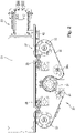
- Figure 1A shows a schematic perspective view of the chassis 50 of the embodiment of a storage vehicle according to the invention.
- the warehouse vehicle can perform any functions within a warehouse and have corresponding structures and handling elements that are not shown here and are independent of the invention.
- the storage vehicle can be used as a shelf vehicle for loading and unloading goods from a high-bay warehouse or as a cross conveyor for connecting different conveyor technology elements such as roller or belt conveyors.
- the invention relates to the drive of the storage vehicle, which storage vehicle can fulfill a wide variety of functions.
- wheel carrier which include wheels 30. These are used to guide the warehouse vehicle through the aisle. However, other wheel arrangements are also possible.
- the guide rail 40 is also shown, which is arranged in a stationary manner in the storage building and defines the route of the storage vehicle. As in particular in the detailed representations of Figures 1B and 1C can be seen, is on the guide rail 40 with a toothed belt 42 engagement elements (teeth) 43 (cf. 4 ) appropriate.
- the toothed belt 42 is preferably made of an elastic material such as a plastic or rubber material, in particular made of polyurethane, and is fixed at certain distances to the guide rail 40 and forms a fixed unit with it. This unit is preferably mounted over the entire length of the aisle/lane of the warehouse and can be fixed to the floor by means of a rail foot or the like.
- the toothed belt 42 fixed to a guide rail 40 has the further advantage of a significantly lower assembly effort, since several toothed rack elements mounted one behind the other must be aligned very precisely with one another, which means a high manufacturing effort. This effort does not apply when using a toothed belt.
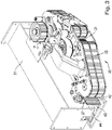
- FIG. 2 shows a schematic horizontal sectional view and 3 a perspective view of the drive unit 20, which accelerates and drives the storage vehicle on the track.
- the drive unit 20 accelerates and drives the storage vehicle on the track.
- a part of the chassis support 51 and one of the running wheels 30 is visible.
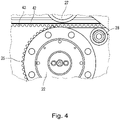
- the engagement elements (teeth) of an endless drive belt 25 engage in the toothed belt 42 21 is guided.
- the toothed side of the endless drive belt 25 is inserted into the toothed belt 42 .
- One or more deflection rollers are designed to be movable as tension roller(s) 24a for setting a suitable tension of the endless drive belt 25.
- the drive wheel 21 is coupled to an electric motor or another suitable drive unit. Due to the omega geometry, the engagement elements of the drive wheel 21 are in engagement with the engagement elements of the endless drive belt 25 over a significant part of the circumference of the drive wheel 21, so that good power transmission from the drive wheel 21 to the endless drive belt 25 is ensured with little maintenance .
- the drive unit 20 is preferably firmly connected to the chassis support 51 of the storage vehicle and can be detached from it by dismantling various components.
- a guide roller 27, in particular in the 3 and 4 is visible, the drive unit 20 is kept at a constant distance from the chassis beam 51, so that a good engagement of the engagement elements of the endless drive belt 25 in the corresponding engagement elements of the toothed belt 42 is possible.
- pressure rollers 28 are provided for the for Force transmission required contact pressure of the endless drive belt 25 on the toothed belt 42 provides. The power transmission from the endless drive belt 25 to the toothed belt 42 is distributed over a large number of pairs of engagement elements, so that the force and thus the wear on the individual engagement elements is reduced.
- noise-reducing materials such as polyurethane and NFC fabric can also be used for the drive wheel 21, the endless drive belt 25 and the toothed belt 42.
- the toothed belt 42 transmits the force via the guide rail 40 and the ground connection to the ground.
- the figures 5 and 6 show a second embodiment of the drive unit 20 of the storage vehicle according to the invention.
- the mode of operation of the second exemplary embodiment essentially corresponds to that of the first exemplary embodiment, but is characterized by a particularly compact design.
- figure 7 again shows a third exemplary embodiment of the drive unit 20 of the storage vehicle according to the invention, which is based on the second exemplary embodiment but differs from it in that two drive motors 60 are attached directly to the drive unit.
- the drive force is transmitted from the motors 60 to the drive shaft of the drive wheel 21 via belt drives 29 .
- a suitable transmission or reduction can be selected between the drive motors 60 and the drive wheel 21 by suitably selecting the diameter of the pulleys.
- the belt drive can also serve as a gear, which means that a heavy and bulky motor gear can be omitted.
- the warehouse vehicle according to the invention thus enables high accelerations and decelerations in both directions of movement, even with heavy loads, and thus an increase in the performance of the associated warehouse.
- the storage vehicle can be moved along the aisle of a rack warehouse or used as a cross conveyor at right angles to the direction of the aisle or to connect different conveyor technology elements such as roller or belt conveyors.
- the drive according to the invention can also be used to drive vertical conveyors.
Landscapes
- Engineering & Computer Science (AREA)
- Transportation (AREA)
- Structural Engineering (AREA)
- Mechanical Engineering (AREA)
- Civil Engineering (AREA)
- Life Sciences & Earth Sciences (AREA)
- Geology (AREA)
- Warehouses Or Storage Devices (AREA)
- Transmission Devices (AREA)
Description
Die Erfindung betrifft einen Antrieb für Fahrzeuge, die in Lagern zum Einsatz kommen, wie beispielsweise Regalbediengeräte zum Ein- und Auslagern von Artikeln in/aus Regallagern.The invention relates to a drive for vehicles that are used in warehouses, such as storage and retrieval devices for storing and retrieving articles in/from storage racks.
Derartige Regalbediengeräte übernehmen zum Beispiel das Bestücken und Entnehmen von Ware aus einem Hochregellager. Hierzu fährt das Regalbediengerät im Regallager zu den jeweiligen Stellplätzen und entnimmt oder bestückt die jeweilige Ware. Die Leistung, d.h. der Warendurchsatz eines solchen Regallagers hängt kritisch von der Geschwindigkeit und insbesondere der möglichen maximalen Beschleunigung der Regalbediengeräte oder anderer Lagerfahrzeuge ab. Dies stellt insbesondere für Fahrzeuge mit hohem Eigengewicht bzw. hohen Nutzlasten hohe Anforderungen an die Antriebstechnik der Lagerfahrzeuge.Such storage and retrieval devices take over, for example, the loading and unloading of goods from a high-bay warehouse. For this purpose, the storage and retrieval device drives to the respective storage locations in the rack storage and removes or loads the respective goods. The performance, i.e. the goods throughput of such a rack storage system depends critically on the speed and in particular the possible maximum acceleration of the stacker cranes or other storage vehicles. This places high demands on the drive technology of the warehouse vehicles, especially for vehicles with a high dead weight or high payload.
Überwiegend werden in der Fahrantriebstechnik für Lagerfahrzeuge zwei unterschiedliche Antriebsvarianten verfolgt:
Beim Reibradantrieb erzeugt die Eigenmasse des Fahrzeugs die Anpresskraft zwischen Antriebsrad und Fahrbahn. Durch die Reibung zwischen Antriebsrad und Fahrbahn kann mittels dieser Anpresskraft eine Vorschubkraft vom Antriebsrad an die Fahrbahn generiert werden, um das Fahrzeug zu beschleunigen. Die Größe des Betrages der Beschleunigung oder Verzögerung hängt dementsprechend vom Reibungskoeffizienten Antriebsrad/Fahrbahn ab. Durch die kraftschlüssige Verbindung zwischen Reibrad und Fahrbahn (ähnlich einem Kraftfahrzeug auf der Straße) können nur relativ kleine Momente übertragen und somit nur vergleichsweise geringe Beschleunigungen bzw. Verzögerungen erzielt werden.Two different drive variants are mainly pursued in the travel drive technology for warehouse vehicles:
With the friction wheel drive, the vehicle's own mass generates the contact pressure between the drive wheel and the road surface. Due to the friction between the drive wheel and the road, this contact pressure force can be used to generate a feed force from the drive wheel to the road in order to accelerate the vehicle. Accordingly, the magnitude of the amount of acceleration or deceleration depends on the friction coefficient of the driving wheel/road. Due to the non-positive connection between the friction wheel and the road (similar to a motor vehicle on the road), only relatively small moments can be transmitted and thus only comparatively small accelerations or decelerations can be achieved.
Beim Zahnstangenantrieb wird eine Zahnstange auf der kompletten Länge des Verfahrweges des Fahrzeugs verbaut. Mithilfe eines in die Zahnstange eingreifenden Antriebszahnrades (Ritzels), welches mit dem Fahrwerk des Lagerfahrzeugs verbunden ist, wird die Rotationsbewegung des angetriebenen Zahnrades in eine translatorische Bewegung umgewandelt. Mit dem Zahnstangenantrieb können hohe Momente übertragen und daher hohe Beschleunigungen und Verzögerungen erzielt werden. Nachteilig ist jedoch der hohe Wartungsaufwand (Schmierung) und die große Lärmentwicklung sowie die vergleichsweise hohen Installationskosten.
Der vorliegenden Erfindung liegt daher die Aufgabe zu Grunde, ein Antriebskonzept für ein Lagerfahrzeug vorzuschlagen, das hohe Beschleunigungs- und Verzögerungswerte bei gleichzeitig niedrigem Wartungsaufwand und Montageaufwand der Antriebselemente ermöglicht.The present invention is therefore based on the object of proposing a drive concept for a storage vehicle that enables high acceleration and deceleration values while at the same time requiring little maintenance and assembly work for the drive elements.
Gelöst wird die Aufgabe durch das in Anspruch 1 beschriebene erfindungsgemäße entlang einer mit Eingriffselementen versehenen Führungsschiene verfahrbares Lagerfahrzeug mit einem Fahrwerk und einer mit dem Fahrwerk verbundenen Antriebseinheit. Die Antriebseinheit weist ein mit einem Antriebsmotor gekoppeltes Antriebsrad mit umfangsseitigen Eingriffselementen, ein mit Eingriffselementen versehenen Endlos-Antriebsriemen, und eine Lenkrollenanordnung zur Führung des Endlos-Antriebsriemens auf, die derart ausgebildet ist, dass der Endlos-Antriebsriemen zum Antrieb des Lagerfahrzeugs sowohl mit dem Antriebsrad als auch mit den Eingriffselementen der Führungsschiene in Eingriff bringbar ist. Die Eingriffselemente oder Zähne des Endlos-Antriebsriemens sind über eine größere Distanz mit den Eingriffselementen der Führungsschiene im Eingriff, ebenso wie die Eingriffselemente des Antriebsrades mit denjenigen des Endlos-Antriebsriemens. Die Antriebskraft wird daher jeweils auf eine Vielzahl von Eingriffselementepaaren verteilt.The object is achieved by the storage vehicle described in claim 1 according to the invention, which can be moved along a guide rail provided with engagement elements and has a chassis and a drive unit connected to the chassis. The drive unit has a drive wheel coupled to a drive motor with engagement elements on the circumference, an endless drive belt provided with engagement elements, and a steering roller arrangement for guiding the endless drive belt, which is designed in such a way that the endless drive belt for driving the storage vehicle can be connected to both the drive wheel and the drive wheel as well as being engageable with the engaging elements of the guide rail. The engagement elements or teeth of the endless drive belt engage the engagement elements of the guide rail over a greater distance, as do the engagement elements of the drive wheel with those of the endless drive belt. The driving force is therefore distributed to a plurality of pairs of engaging elements, respectively.
Der erfindungsgemäße Antrieb ermöglicht so hohe Beschleunigungs- und Verzögerungswerte in beide Bewegungsrichtungen auch bei großen Lasten und damit eine hohe Leistungsfähigkeit des Lagerfahrzeugs bei gleichzeitig geringem Wartungsaufwand und geringer Lärmentwicklung.The drive according to the invention thus enables high acceleration and deceleration values in both directions of movement, even with heavy loads, and thus high performance of the storage vehicle with low maintenance costs and low noise development at the same time.
Vorzugsweise ist der Endlos-Antriebsriemen in einer Omega-Geometrie derart um das Antriebsrad und die Lenkrollenanordnung geführt, dass die Eingriffselemente auf der gleichen Seite des Endlos-Antriebsriemens sowohl mit dem Antriebsrad als auch mit der mit Eingriffselementen versehenen Führungsschiene in Eingriff kommen. Die Omega-Geometrie ermöglicht eine "kompakte" Bauweise des Antriebes.Preferably, the endless drive belt is routed in an omega geometry around the drive wheel and caster wheel assembly such that the engagement elements on the same side of the endless drive belt engage both the drive wheel and the guide rail provided with engagement elements. The omega geometry enables a "compact" construction of the drive.
Die Lenkrollenanordnung umfasst vorzugsweise zwei führungsschienenseitige Umlenkrollen und zwei von der Führungsschiene abgewandte Umlenkrollen, wobei eine oder mehrere der Umlenkrollen als Spannrolle zum Spannen des Endlos-Antriebsriemens ausgebildet sein kann.The guide roller arrangement preferably comprises two deflection rollers on the guide rail side and two deflection rollers facing away from the guide rail, it being possible for one or more of the deflection rollers to be designed as a tensioning roller for tensioning the endless drive belt.
Ferner kann die Antriebseinheit Anpresselemente, vorzugsweise Anpressrollen, zum Anpressen des Endlos-Antriebsriemens an die mit Eingriffselementen versehene Führungsschiene aufweisen.Furthermore, the drive unit can have pressure elements, preferably pressure rollers, for pressing the endless drive belt against the guide rail provided with engagement elements.
Der Endlos-Antriebsriemen kann aus elastischem Material wie Kunststoff- oder Gummimaterial, vorzugsweise aus Polyurethan ausgebildet sein. Der Einsatz eines NFC-Gewebes kann die Geräuschentwicklung weiter reduzieren.The endless drive belt can be made of elastic material such as plastic or rubber material, preferably made of polyurethane. The use of an NFC fabric can further reduce the noise development.
Das Lagerfahrzeug weist vorzugsweise Führungsrollen zur Aufrechterhaltung eines definierten Abstandes zwischen Antriebseinheit und Führungsschiene auf.The storage vehicle preferably has guide rollers to maintain a defined distance between the drive unit and the guide rail.
Die Antriebseinheit kann einen oder mehrere Antriebsmotoren aufweisen, der/die über einen Riemenantrieb mit der Achse des Antriebsrads gekoppelt ist/sind. Der Riemenantrieb kann dabei durch die Wahl geeigneter Durchmesser der Riemenräder eine Über- oder Untersetzung aufweisen und so als Getriebe dienen. Dadurch kann sich ein an dem Antriebsmotor angeflanschtes Getriebe erübrigen, wodurch erheblich Gewicht eingespart werden kann.The drive unit can have one or more drive motors, which is/are coupled to the axle of the drive wheel via a belt drive. By selecting a suitable diameter for the belt wheels, the belt drive can have a step-up or step-down and can thus serve as a gear. As a result, a gear flanged to the drive motor can be dispensed with, as a result of which a considerable weight can be saved.
Alternativ kann der Antriebsmotor separat von der Antriebseinheit angeordnet sein.Alternatively, the drive motor can be arranged separately from the drive unit.
Das Fahrwerk des Lagerfahrzeugs weist vorzugsweise einen Fahrwerkskörper sowie eine oder mehrere Laufräder auf.The chassis of the storage vehicle preferably has a chassis body and one or more running wheels.
Die Erfindung betrifft ferner ein Lagerfahrzeugsystem aufweisend eine mit Eingriffselementen versehenen Führungsschiene sowie ein entlang der Führungsschiene verfahrbares erfindungsgemäßes Lagerfahrzeug.The invention further relates to a storage vehicle system having a guide rail provided with engagement elements and a storage vehicle according to the invention that can be moved along the guide rail.
Die Eingriffselemente der Führungsschiene können durch an dieser angebrachte Zahnriemen gebildet sein. Die Zahnriemen können dabei aus elastischem Material, vorzugsweise aus Polyurethan ausgebildet sein. Auch hier kann NFC-Gewebe zur Verringerung der Geräuschentwicklung zum Einsatz kommen. Die Zahnriemen sind vorzugsweise in gewissen Abständen an der Führungsschiene fixiert.The engagement elements of the guide rail can be formed by toothed belts attached to it. The toothed belts can be made of elastic material, preferably made of polyurethane. NFC fabric can also be used here to reduce noise. The toothed belts are preferably fixed to the guide rail at certain intervals.
Die Erfindung betrifft ferner Lager welche ein oder mehrere erfindungsgemäße Lagerfahrzeugsysteme aufweisen, wobei die Führungsschienen in Längs- und/oder Querrichtung oder auch in vertikaler Richtung entsprechend einer Bewegungsrichtung des jeweiligen Lagerfahrzeugs angeordnet sind.The invention also relates to warehouses which have one or more warehouse vehicle systems according to the invention, the guide rails being arranged in the longitudinal and/or transverse direction or also in the vertical direction corresponding to a direction of movement of the respective warehouse vehicle.
Die Erfindung wird nachstehend anhand von Ausführungsbeispielen unter Bezugnahme auf die Zeichnungen im Einzelnen beschrieben. Dabei zeigt:
- Fig. 1
- eine schematische perspektivische Darstellung eines ersten Ausführungsbeispiels des Fahrwerks eines erfindungsgemäßen Lagerfahrzeugs ohne Antriebselement;
- Fig. 2
- eine schematische Horizontalschnittansicht des Antriebselements des ersten Ausführungsbeispiels des erfindungsgemäßen Lagerfahrzeugs;
- Fig. 3
- eine schematische perspektivische Darstellung des Antriebselements gemäß
Fig. 2 ; - Fig. 4
- eine schematische Detaildarstellung des Antriebselements gemäß
Fig. 2 ; - Fig. 5
- eine schematische Horizontalschnittansicht des Antriebselements eines zweiten Ausführungsbeispiels des erfindungsgemäßen Lagerfahrzeugs;
- Fig. 6
- eine schematische perspektivische Darstellung des Antriebselements gemäß
Fig. 5 ; und - Fig. 7
- eine schematische perspektivische Darstellung des Antriebselements eines dritten Ausführungsbeispiels des erfindungsgemäßen Lagerfahrzeugs.
- 1
- a schematic perspective view of a first embodiment of the chassis of a storage vehicle according to the invention without a drive element;
- 2
- a schematic horizontal sectional view of the drive element of the first embodiment of the storage vehicle according to the invention;
- 3
- a schematic perspective view of the drive element according to FIG
2 ; - 4
- a schematic detailed representation of the drive element according to FIG
2 ; - figure 5
- a schematic horizontal sectional view of the drive element of a second embodiment of the storage vehicle according to the invention;
- 6
- a schematic perspective view of the drive element according to FIG
figure 5 ; and - Figure 7
- a schematic perspective view of the drive element of a third embodiment of the storage vehicle according to the invention.
Die
Am Fahrwerk 50 des in
In
In den Zahnriemen 42 greifen die Eingriffselemente (Zähne) eines Endlos-Antriebsriemens 25 ein, der in dem gezeigten Ausführungsbeispiel in einer Omega-Geometrie um eine Anordnung von Umlenkrollen 22, 24, 24a sowie ein ebenfalls mit Eingriffselementen (Zähnen) versehenes Antriebsrad bzw. Antriebsscheibe 21 geführt ist. Dabei wird die Zahnseite des Endlos-Antriebsriemens 25 in den Zahnriemen 42 eingeführt. Eine oder mehrere Umlenkrollen sind beweglich als Spannrolle(n) 24a zum Einstellen einer geeigneten Spannung des Endlos-Antriebsriemens 25 ausgebildet.The engagement elements (teeth) of an
Das Antriebsrad 21 ist mit einem Elektromotor oder einer anderen geeigneten Antriebseinheit gekoppelt. Aufgrund der Omega-Geometrie sind die Eingriffselemente des Antriebsrades 21 über einen erheblichen Teil des Umfangs des Antriebsrades 21 im Eingriff mit den Eingriffselementen des Endlos-Antriebsriemens 25, so dass eine gute Kraftübertragung vom Antriebsrad 21 auf den Endlos-Antriebsriemen 25 bei geringem Wartungsaufwand gewährleistet ist.The
Die Antriebseinheit 20 ist vorzugsweise fest mit dem Fahrwerksträger 51 des Lagerfahrzeugs verbunden und kann durch Demontage diverser Bauteile von diesem gelöst werden. Mittels einer Führungsrolle 27, die insbesondere in den
Die
Das erfindungsgemäße Lagerfahrzeug ermöglicht so hohe Beschleunigungen und Verzögerungen in beide Bewegungsrichtungen auch bei großen Lasten und damit eine Leistungssteigerung des zugehörigen Lagers. Das Lagerfahrzeug kann entlang der Regalgasse eines Regallagers verfahrbar oder auch als Querförderer quer zur Regalgassenrichtung oder zum Verbinden von verschiedenen Fördertechnikelementen wie Rollen- oder Bandförderern eingesetzt werden. Der erfindungsgemäße Antrieb ist außerdem zum Antrieb von Vertikalförderern einsetzbar.The warehouse vehicle according to the invention thus enables high accelerations and decelerations in both directions of movement, even with heavy loads, and thus an increase in the performance of the associated warehouse. The storage vehicle can be moved along the aisle of a rack warehouse or used as a cross conveyor at right angles to the direction of the aisle or to connect different conveyor technology elements such as roller or belt conveyors. The drive according to the invention can also be used to drive vertical conveyors.
Claims (15)
- A warehouse vehicle which can be moved along a guide rail (40) provided with engagement elements (43), having a chassis (50) and a drive unit (20) connected to the chassis (50), wherein the drive unit (20) has
a drive wheel (21) coupled to a drive motor (60), wherein the drive wheel (21) comprises peripheral contact elements, characterised in that the warehouse vehicle comprises:an endless drive belt (25) provided with contact elements,a guide roller arrangement (22, 24, 24a) for guiding said endless drive belt (25), wherein said guide roller arrangement (22, 24, 24a) is configured in such that the endless drive belt (25) is engageable with both the drive wheel (21) and the engagement elements (43) of the guide rail (40) to drive the warehouse vehicle. - The warehouse vehicle according to claim 1, wherein the endless drive belt (25) is guided in an omega geometry around the drive wheel (21) and the guide roller arrangement (22, 24, 24a) in such a way that the engagement elements on the same side of the endless drive belt (25) engage with both the drive wheel (21) and the guide rail (40) provided with the engagement elements (43).
- The warehouse vehicle according to claim 2, wherein the guide roller arrangement (22, 24, 24a) comprises two guide rail side guide rollers (22) and two guide rollers (24, 24a) facing away from the guide rail (40).
- The warehouse vehicle according to claim 3, wherein at least one of the guide rollers (24a) is designed as a displaceable tensioning roller for tensioning the endless drive belt (25).
- The warehouse vehicle according to claim 4, comprising pressing elements (28) for pressing the endless drive belt (25) against the guide rail (40) provided with engagement elements (43).
- The warehouse vehicle according to claim 5, wherein the pressing elements (28) are designed as pressing rollers.
- The warehouse vehicle according to any one of claims 1-6, comprising one or more guide rollers (27) for maintaining a defined distance between the drive unit (20) and guide rail (40).
- The warehouse vehicle according to any one of claims 1-7, wherein the endless drive belt (25) is formed of elastic material, preferably polyurethane.
- The warehouse vehicle according to any one of claims 1-8, wherein the drive unit (20) comprises at least one drive motor (60) coupled to the axle of the drive wheel (21) via a belt drive (29).
- The warehouse vehicle according to claim 9, wherein the belt drive (29) realises an increase or reduction of the driving force.
- The warehouse vehicle according to any one of claims 1-10, wherein the chassis (50) comprises a chassis body (51) and one or more running wheels (30).
- A warehouse vehicle system comprising a guide rail (40) provided with engagement elements (43) and a warehouse vehicle movable along the guide rail (40) according to any one of claims 1-11.
- The warehouse vehicle system according to claim 12, wherein the engagement elements (43) are formed by toothed belts (42) applied to the guide rail.
- The warehouse vehicle system according to claim 13, wherein the toothed belts (42) are formed of elastic material, preferably polyurethane, and are fixed at intervals to the guide rail (40).
- A warehouse comprising one or more warehouse vehicle systems according to one of the claims 12-14, wherein the guide rails (40) are arranged in a longitudinal and/or transverse direction or, in addition, in a vertical direction, corresponding to a direction of movement of the respective warehouse vehicle.
Applications Claiming Priority (2)
| Application Number | Priority Date | Filing Date | Title |
|---|---|---|---|
| DE102020102828.8A DE102020102828B4 (en) | 2020-02-04 | 2020-02-04 | TRACKED DRIVE FOR STOCK VEHICLE |
| PCT/EP2021/051258 WO2021156062A1 (en) | 2020-02-04 | 2021-01-21 | Warehouse vehicle having a tracked drive |
Publications (2)
| Publication Number | Publication Date |
|---|---|
| EP3914552A1 EP3914552A1 (en) | 2021-12-01 |
| EP3914552B1 true EP3914552B1 (en) | 2022-11-02 |
Family
ID=74285458
Family Applications (1)
| Application Number | Title | Priority Date | Filing Date |
|---|---|---|---|
| EP21701950.4A Active EP3914552B1 (en) | 2020-02-04 | 2021-01-21 | Warehouse vehicle having a tracked drive |
Country Status (8)
| Country | Link |
|---|---|
| US (1) | US20230059295A1 (en) |
| EP (1) | EP3914552B1 (en) |
| AU (1) | AU2021215788B2 (en) |
| CA (1) | CA3163368C (en) |
| DE (1) | DE102020102828B4 (en) |
| ES (1) | ES2936308T3 (en) |
| FI (1) | FI3914552T3 (en) |
| WO (1) | WO2021156062A1 (en) |
Families Citing this family (1)
| Publication number | Priority date | Publication date | Assignee | Title |
|---|---|---|---|---|
| DE102023131012A1 (en) * | 2023-11-08 | 2025-05-08 | Ltw Intralogistics Gmbh | Channel vehicle and storage and retrieval system with such a |
Family Cites Families (15)
| Publication number | Priority date | Publication date | Assignee | Title |
|---|---|---|---|---|
| US3946836A (en) * | 1974-11-25 | 1976-03-30 | Maack Norris N | Elevator system having co-moving and short-length annular-belt for suspending and propelling the carriage |
| DE2540252A1 (en) | 1975-09-10 | 1977-03-17 | Adolf Theobald | Palletised flat item storage system - has portal loading machine travelling over movable shelf sets on rails |
| DE3813897A1 (en) * | 1988-04-21 | 1989-11-09 | Mannesmann Ag | WORK TOOL |
| DE9304210U1 (en) * | 1993-03-20 | 1993-06-17 | C. Haushahn Automationssysteme GmbH, 7000 Stuttgart | Storage and retrieval machine |
| CA2096703A1 (en) * | 1993-04-02 | 1994-10-03 | Kurt M. Lloyd | Automatic storage and retrieval system |
| US5452774A (en) * | 1993-10-25 | 1995-09-26 | Davis; Link H. | Endless roller chain drive with interlocking traction rail |
| AT500378B1 (en) * | 2001-06-13 | 2006-12-15 | Tgw Transportgeraete Gmbh | STACKER UNIT |
| DE10216014B4 (en) | 2002-04-11 | 2006-04-27 | Knapp Logistik Automation Ges.M.B.H. | Movable stacker crane, preferably in a picking system |
| JP2006193271A (en) * | 2005-01-13 | 2006-07-27 | Shin Meiwa Ind Co Ltd | Conveyor crane and conveyor crane equipment |
| JP4538735B2 (en) * | 2005-03-25 | 2010-09-08 | 株式会社ダイフク | Lift device |
| US7478597B2 (en) * | 2006-10-06 | 2009-01-20 | Pacific Bearing Company | Multi-axis gantry system |
| AT507334B1 (en) | 2008-09-08 | 2012-04-15 | Swisslog Evomatic Gmbh | STACKER UNIT |
| US8875636B2 (en) * | 2011-04-14 | 2014-11-04 | Production Resource Group, Llc | Universal powerpack and attachments |
| CN106217410B (en) | 2016-08-25 | 2018-06-19 | 宁波朝平智能科技有限公司 | Axis is moved for the section of full-automatic compact shelving repository box taking machine tool hand |
| ES2875750T3 (en) | 2018-07-09 | 2021-11-11 | Jungheinrich Ag | Transport device |
-
2020
- 2020-02-04 DE DE102020102828.8A patent/DE102020102828B4/en active Active
-
2021
- 2021-01-21 US US17/759,936 patent/US20230059295A1/en not_active Abandoned
- 2021-01-21 ES ES21701950T patent/ES2936308T3/en active Active
- 2021-01-21 FI FIEP21701950.4T patent/FI3914552T3/en active
- 2021-01-21 AU AU2021215788A patent/AU2021215788B2/en active Active
- 2021-01-21 WO PCT/EP2021/051258 patent/WO2021156062A1/en not_active Ceased
- 2021-01-21 EP EP21701950.4A patent/EP3914552B1/en active Active
- 2021-01-21 CA CA3163368A patent/CA3163368C/en active Active
Also Published As
| Publication number | Publication date |
|---|---|
| AU2021215788A1 (en) | 2022-07-21 |
| ES2936308T3 (en) | 2023-03-16 |
| CA3163368C (en) | 2025-05-06 |
| AU2021215788B2 (en) | 2024-11-21 |
| DE102020102828B4 (en) | 2025-12-11 |
| DE102020102828A1 (en) | 2021-08-05 |
| US20230059295A1 (en) | 2023-02-23 |
| CA3163368A1 (en) | 2021-08-12 |
| WO2021156062A1 (en) | 2021-08-12 |
| FI3914552T3 (en) | 2023-01-31 |
| EP3914552A1 (en) | 2021-12-01 |
Similar Documents
| Publication | Publication Date | Title |
|---|---|---|
| DE68920795T2 (en) | Transport device. | |
| EP1886961B1 (en) | Lift belt for a lift system and method for manufacturing such a lift belt | |
| DE69707991T2 (en) | Rail system for a load handling device | |
| EP1700811B1 (en) | Elevator | |
| EP2218662A2 (en) | Lifting bar conveyor | |
| DE102012006832A1 (en) | DRAWER FOR A DRAWER, DRAWER WITH AN EXTRACT AND VEHICLE WITH A DRAWER | |
| WO2018077670A1 (en) | Conveying system | |
| DE20307005U1 (en) | Powered pallet trolley for automated warehouse has a lever-operated gear also linked to the motor and lifting platform | |
| EP1958918B1 (en) | Load handling device with roller body movement | |
| AT515733B1 (en) | Cableway system | |
| EP3914552B1 (en) | Warehouse vehicle having a tracked drive | |
| AT518568B1 (en) | Storage and retrieval unit | |
| EP0391247A2 (en) | Conveyor belt having accumulating rollers | |
| DE202005017269U1 (en) | Storage racking has first transporting means which consists of several detachably interconnected modules, the number of which is variable in dependence upon number of rack units | |
| EP3205607B1 (en) | Method and device for supplying a shelf transport vehicle | |
| DE1580875B2 (en) | Adhesion caterpillar for driving self-propelled cable car vehicles | |
| DE102012009062A1 (en) | Transport unit of transportation system for transporting frame modules for processing car chassis, has motor that is driven by drive units for generating relative movement of main portion relative to guide rail | |
| EP2493786B1 (en) | Storage system having drive means that can be tensioned independently | |
| DE2545010B2 (en) | Displacement drive for a carrier that can be moved into the shelf compartment on the lifting carriage of a storage and retrieval vehicle | |
| CH687147A5 (en) | Drive a stacker crane for high-bay warehouse. | |
| WO2019110323A1 (en) | Raceway, conveyor device, and method for mounting a raceway | |
| DE102017114576A1 (en) | Lifting device and method for moving a lifting carriage | |
| DE3817887A1 (en) | DEVICE FOR LOADING AND UNLOADING PARTS | |
| EP0288730B1 (en) | Device for transporting and storing objects | |
| EP1362821A1 (en) | Straddle carrier |
Legal Events
| Date | Code | Title | Description |
|---|---|---|---|
| STAA | Information on the status of an ep patent application or granted ep patent |
Free format text: STATUS: UNKNOWN |
|
| STAA | Information on the status of an ep patent application or granted ep patent |
Free format text: STATUS: THE INTERNATIONAL PUBLICATION HAS BEEN MADE |
|
| PUAI | Public reference made under article 153(3) epc to a published international application that has entered the european phase |
Free format text: ORIGINAL CODE: 0009012 |
|
| STAA | Information on the status of an ep patent application or granted ep patent |
Free format text: STATUS: REQUEST FOR EXAMINATION WAS MADE |
|
| 17P | Request for examination filed |
Effective date: 20210826 |
|
| AK | Designated contracting states |
Kind code of ref document: A1 Designated state(s): AL AT BE BG CH CY CZ DE DK EE ES FI FR GB GR HR HU IE IS IT LI LT LU LV MC MK MT NL NO PL PT RO RS SE SI SK SM TR |
|
| GRAP | Despatch of communication of intention to grant a patent |
Free format text: ORIGINAL CODE: EPIDOSNIGR1 |
|
| STAA | Information on the status of an ep patent application or granted ep patent |
Free format text: STATUS: GRANT OF PATENT IS INTENDED |
|
| INTG | Intention to grant announced |
Effective date: 20220822 |
|
| GRAS | Grant fee paid |
Free format text: ORIGINAL CODE: EPIDOSNIGR3 |
|
| GRAA | (expected) grant |
Free format text: ORIGINAL CODE: 0009210 |
|
| STAA | Information on the status of an ep patent application or granted ep patent |
Free format text: STATUS: THE PATENT HAS BEEN GRANTED |
|
| DAV | Request for validation of the european patent (deleted) | ||
| DAX | Request for extension of the european patent (deleted) | ||
| AK | Designated contracting states |
Kind code of ref document: B1 Designated state(s): AL AT BE BG CH CY CZ DE DK EE ES FI FR GB GR HR HU IE IS IT LI LT LU LV MC MK MT NL NO PL PT RO RS SE SI SK SM TR |
|
| REG | Reference to a national code |
Ref country code: GB Ref legal event code: FG4D Free format text: NOT ENGLISH |
|
| REG | Reference to a national code |
Ref country code: CH Ref legal event code: EP Ref country code: AT Ref legal event code: REF Ref document number: 1528636 Country of ref document: AT Kind code of ref document: T Effective date: 20221115 |
|
| REG | Reference to a national code |
Ref country code: DE Ref legal event code: R096 Ref document number: 502021000238 Country of ref document: DE |
|
| REG | Reference to a national code |
Ref country code: NO Ref legal event code: T2 Effective date: 20221102 |
|
| REG | Reference to a national code |
Ref country code: IE Ref legal event code: FG4D Free format text: LANGUAGE OF EP DOCUMENT: GERMAN |
|
| REG | Reference to a national code |
Ref country code: SE Ref legal event code: TRGR |
|
| REG | Reference to a national code |
Ref country code: NL Ref legal event code: FP |
|
| REG | Reference to a national code |
Ref country code: FI Ref legal event code: FGE |
|
| REG | Reference to a national code |
Ref country code: LT Ref legal event code: MG9D |
|
| REG | Reference to a national code |
Ref country code: ES Ref legal event code: FG2A Ref document number: 2936308 Country of ref document: ES Kind code of ref document: T3 Effective date: 20230316 |
|
| PG25 | Lapsed in a contracting state [announced via postgrant information from national office to epo] |
Ref country code: PT Free format text: LAPSE BECAUSE OF FAILURE TO SUBMIT A TRANSLATION OF THE DESCRIPTION OR TO PAY THE FEE WITHIN THE PRESCRIBED TIME-LIMIT Effective date: 20230302 Ref country code: LT Free format text: LAPSE BECAUSE OF FAILURE TO SUBMIT A TRANSLATION OF THE DESCRIPTION OR TO PAY THE FEE WITHIN THE PRESCRIBED TIME-LIMIT Effective date: 20221102 |
|
| PG25 | Lapsed in a contracting state [announced via postgrant information from national office to epo] |
Ref country code: RS Free format text: LAPSE BECAUSE OF FAILURE TO SUBMIT A TRANSLATION OF THE DESCRIPTION OR TO PAY THE FEE WITHIN THE PRESCRIBED TIME-LIMIT Effective date: 20221102 Ref country code: PL Free format text: LAPSE BECAUSE OF FAILURE TO SUBMIT A TRANSLATION OF THE DESCRIPTION OR TO PAY THE FEE WITHIN THE PRESCRIBED TIME-LIMIT Effective date: 20221102 Ref country code: LV Free format text: LAPSE BECAUSE OF FAILURE TO SUBMIT A TRANSLATION OF THE DESCRIPTION OR TO PAY THE FEE WITHIN THE PRESCRIBED TIME-LIMIT Effective date: 20221102 Ref country code: IS Free format text: LAPSE BECAUSE OF FAILURE TO SUBMIT A TRANSLATION OF THE DESCRIPTION OR TO PAY THE FEE WITHIN THE PRESCRIBED TIME-LIMIT Effective date: 20230302 Ref country code: HR Free format text: LAPSE BECAUSE OF FAILURE TO SUBMIT A TRANSLATION OF THE DESCRIPTION OR TO PAY THE FEE WITHIN THE PRESCRIBED TIME-LIMIT Effective date: 20221102 Ref country code: GR Free format text: LAPSE BECAUSE OF FAILURE TO SUBMIT A TRANSLATION OF THE DESCRIPTION OR TO PAY THE FEE WITHIN THE PRESCRIBED TIME-LIMIT Effective date: 20230203 |
|
| P01 | Opt-out of the competence of the unified patent court (upc) registered |
Effective date: 20230522 |
|
| PG25 | Lapsed in a contracting state [announced via postgrant information from national office to epo] |
Ref country code: SM Free format text: LAPSE BECAUSE OF FAILURE TO SUBMIT A TRANSLATION OF THE DESCRIPTION OR TO PAY THE FEE WITHIN THE PRESCRIBED TIME-LIMIT Effective date: 20221102 Ref country code: RO Free format text: LAPSE BECAUSE OF FAILURE TO SUBMIT A TRANSLATION OF THE DESCRIPTION OR TO PAY THE FEE WITHIN THE PRESCRIBED TIME-LIMIT Effective date: 20221102 Ref country code: EE Free format text: LAPSE BECAUSE OF FAILURE TO SUBMIT A TRANSLATION OF THE DESCRIPTION OR TO PAY THE FEE WITHIN THE PRESCRIBED TIME-LIMIT Effective date: 20221102 Ref country code: DK Free format text: LAPSE BECAUSE OF FAILURE TO SUBMIT A TRANSLATION OF THE DESCRIPTION OR TO PAY THE FEE WITHIN THE PRESCRIBED TIME-LIMIT Effective date: 20221102 Ref country code: CZ Free format text: LAPSE BECAUSE OF FAILURE TO SUBMIT A TRANSLATION OF THE DESCRIPTION OR TO PAY THE FEE WITHIN THE PRESCRIBED TIME-LIMIT Effective date: 20221102 |
|
| REG | Reference to a national code |
Ref country code: DE Ref legal event code: R097 Ref document number: 502021000238 Country of ref document: DE |
|
| PG25 | Lapsed in a contracting state [announced via postgrant information from national office to epo] |
Ref country code: SK Free format text: LAPSE BECAUSE OF FAILURE TO SUBMIT A TRANSLATION OF THE DESCRIPTION OR TO PAY THE FEE WITHIN THE PRESCRIBED TIME-LIMIT Effective date: 20221102 Ref country code: AL Free format text: LAPSE BECAUSE OF FAILURE TO SUBMIT A TRANSLATION OF THE DESCRIPTION OR TO PAY THE FEE WITHIN THE PRESCRIBED TIME-LIMIT Effective date: 20221102 |
|
| PLBE | No opposition filed within time limit |
Free format text: ORIGINAL CODE: 0009261 |
|
| STAA | Information on the status of an ep patent application or granted ep patent |
Free format text: STATUS: NO OPPOSITION FILED WITHIN TIME LIMIT |
|
| PG25 | Lapsed in a contracting state [announced via postgrant information from national office to epo] |
Ref country code: LU Free format text: LAPSE BECAUSE OF NON-PAYMENT OF DUE FEES Effective date: 20230121 |
|
| 26N | No opposition filed |
Effective date: 20230803 |
|
| PG25 | Lapsed in a contracting state [announced via postgrant information from national office to epo] |
Ref country code: SI Free format text: LAPSE BECAUSE OF FAILURE TO SUBMIT A TRANSLATION OF THE DESCRIPTION OR TO PAY THE FEE WITHIN THE PRESCRIBED TIME-LIMIT Effective date: 20221102 |
|
| PG25 | Lapsed in a contracting state [announced via postgrant information from national office to epo] |
Ref country code: IE Free format text: LAPSE BECAUSE OF NON-PAYMENT OF DUE FEES Effective date: 20230121 |
|
| PG25 | Lapsed in a contracting state [announced via postgrant information from national office to epo] |
Ref country code: MC Free format text: LAPSE BECAUSE OF FAILURE TO SUBMIT A TRANSLATION OF THE DESCRIPTION OR TO PAY THE FEE WITHIN THE PRESCRIBED TIME-LIMIT Effective date: 20221102 |
|
| PG25 | Lapsed in a contracting state [announced via postgrant information from national office to epo] |
Ref country code: MC Free format text: LAPSE BECAUSE OF FAILURE TO SUBMIT A TRANSLATION OF THE DESCRIPTION OR TO PAY THE FEE WITHIN THE PRESCRIBED TIME-LIMIT Effective date: 20221102 |
|
| PG25 | Lapsed in a contracting state [announced via postgrant information from national office to epo] |
Ref country code: BG Free format text: LAPSE BECAUSE OF FAILURE TO SUBMIT A TRANSLATION OF THE DESCRIPTION OR TO PAY THE FEE WITHIN THE PRESCRIBED TIME-LIMIT Effective date: 20221102 |
|
| PG25 | Lapsed in a contracting state [announced via postgrant information from national office to epo] |
Ref country code: BG Free format text: LAPSE BECAUSE OF FAILURE TO SUBMIT A TRANSLATION OF THE DESCRIPTION OR TO PAY THE FEE WITHIN THE PRESCRIBED TIME-LIMIT Effective date: 20221102 |
|
| PGFP | Annual fee paid to national office [announced via postgrant information from national office to epo] |
Ref country code: NL Payment date: 20250122 Year of fee payment: 5 |
|
| PGFP | Annual fee paid to national office [announced via postgrant information from national office to epo] |
Ref country code: DE Payment date: 20250131 Year of fee payment: 5 |
|
| PGFP | Annual fee paid to national office [announced via postgrant information from national office to epo] |
Ref country code: FI Payment date: 20250121 Year of fee payment: 5 |
|
| PGFP | Annual fee paid to national office [announced via postgrant information from national office to epo] |
Ref country code: ES Payment date: 20250214 Year of fee payment: 5 |
|
| PGFP | Annual fee paid to national office [announced via postgrant information from national office to epo] |
Ref country code: SE Payment date: 20250122 Year of fee payment: 5 |
|
| PGFP | Annual fee paid to national office [announced via postgrant information from national office to epo] |
Ref country code: NO Payment date: 20250121 Year of fee payment: 5 |
|
| PGFP | Annual fee paid to national office [announced via postgrant information from national office to epo] |
Ref country code: BE Payment date: 20250121 Year of fee payment: 5 Ref country code: CH Payment date: 20250201 Year of fee payment: 5 Ref country code: AT Payment date: 20250417 Year of fee payment: 5 |
|
| PGFP | Annual fee paid to national office [announced via postgrant information from national office to epo] |
Ref country code: FR Payment date: 20250122 Year of fee payment: 5 |
|
| PGFP | Annual fee paid to national office [announced via postgrant information from national office to epo] |
Ref country code: GB Payment date: 20250123 Year of fee payment: 5 Ref country code: IT Payment date: 20250131 Year of fee payment: 5 |
|
| PG25 | Lapsed in a contracting state [announced via postgrant information from national office to epo] |
Ref country code: CY Free format text: LAPSE BECAUSE OF FAILURE TO SUBMIT A TRANSLATION OF THE DESCRIPTION OR TO PAY THE FEE WITHIN THE PRESCRIBED TIME-LIMIT; INVALID AB INITIO Effective date: 20210121 |
|
| PG25 | Lapsed in a contracting state [announced via postgrant information from national office to epo] |
Ref country code: HU Free format text: LAPSE BECAUSE OF FAILURE TO SUBMIT A TRANSLATION OF THE DESCRIPTION OR TO PAY THE FEE WITHIN THE PRESCRIBED TIME-LIMIT; INVALID AB INITIO Effective date: 20210121 |
|
| PG25 | Lapsed in a contracting state [announced via postgrant information from national office to epo] |
Ref country code: TR Free format text: LAPSE BECAUSE OF FAILURE TO SUBMIT A TRANSLATION OF THE DESCRIPTION OR TO PAY THE FEE WITHIN THE PRESCRIBED TIME-LIMIT Effective date: 20221102 |