EP3913320B1 - Kupplungselement zur aufnahme einer tastspitze in einem tastmessgerät, schraubeinsatz zur aufnahme einer tastspitze in einem tastmessgerät, kupplungsanordnung für einen tasteinsatz bei einem tastmessgerät, tastmessgerät(-e) - Google Patents
Kupplungselement zur aufnahme einer tastspitze in einem tastmessgerät, schraubeinsatz zur aufnahme einer tastspitze in einem tastmessgerät, kupplungsanordnung für einen tasteinsatz bei einem tastmessgerät, tastmessgerät(-e) Download PDFInfo
- Publication number
- EP3913320B1 EP3913320B1 EP21170513.2A EP21170513A EP3913320B1 EP 3913320 B1 EP3913320 B1 EP 3913320B1 EP 21170513 A EP21170513 A EP 21170513A EP 3913320 B1 EP3913320 B1 EP 3913320B1
- Authority
- EP
- European Patent Office
- Prior art keywords
- coupling
- probe
- thread
- measuring apparatus
- insert
- Prior art date
- Legal status (The legal status is an assumption and is not a legal conclusion. Google has not performed a legal analysis and makes no representation as to the accuracy of the status listed.)
- Active
Links
Images




Classifications
-
- G—PHYSICS
- G01—MEASURING; TESTING
- G01B—MEASURING LENGTH, THICKNESS OR SIMILAR LINEAR DIMENSIONS; MEASURING ANGLES; MEASURING AREAS; MEASURING IRREGULARITIES OF SURFACES OR CONTOURS
- G01B21/00—Measuring arrangements or details thereof, where the measuring technique is not covered by the other groups of this subclass, unspecified or not relevant
- G01B21/10—Measuring arrangements or details thereof, where the measuring technique is not covered by the other groups of this subclass, unspecified or not relevant for measuring diameters
- G01B21/14—Measuring arrangements or details thereof, where the measuring technique is not covered by the other groups of this subclass, unspecified or not relevant for measuring diameters internal diameters
-
- G—PHYSICS
- G01—MEASURING; TESTING
- G01B—MEASURING LENGTH, THICKNESS OR SIMILAR LINEAR DIMENSIONS; MEASURING ANGLES; MEASURING AREAS; MEASURING IRREGULARITIES OF SURFACES OR CONTOURS
- G01B5/00—Measuring arrangements characterised by the use of mechanical techniques
- G01B5/004—Measuring arrangements characterised by the use of mechanical techniques for measuring coordinates of points
- G01B5/008—Measuring arrangements characterised by the use of mechanical techniques for measuring coordinates of points using coordinate measuring machines
- G01B5/012—Contact-making feeler heads therefor
-
- H—ELECTRICITY
- H01—ELECTRIC ELEMENTS
- H01R—ELECTRICALLY-CONDUCTIVE CONNECTIONS; STRUCTURAL ASSOCIATIONS OF A PLURALITY OF MUTUALLY-INSULATED ELECTRICAL CONNECTING ELEMENTS; COUPLING DEVICES; CURRENT COLLECTORS
- H01R13/00—Details of coupling devices of the kinds covered by groups H01R12/70 or H01R24/00 - H01R33/00
- H01R13/40—Securing contact members in or to a base or case; Insulating of contact members
- H01R13/42—Securing in a demountable manner
-
- B—PERFORMING OPERATIONS; TRANSPORTING
- B23—MACHINE TOOLS; METAL-WORKING NOT OTHERWISE PROVIDED FOR
- B23B—TURNING; BORING
- B23B31/00—Chucks; Expansion mandrels; Adaptations thereof for remote control
- B23B31/02—Chucks
- B23B31/10—Chucks characterised by the retaining or gripping devices or their immediate operating means
- B23B31/11—Retention by threaded connection
-
- B—PERFORMING OPERATIONS; TRANSPORTING
- B23—MACHINE TOOLS; METAL-WORKING NOT OTHERWISE PROVIDED FOR
- B23B—TURNING; BORING
- B23B31/00—Chucks; Expansion mandrels; Adaptations thereof for remote control
- B23B31/02—Chucks
- B23B31/10—Chucks characterised by the retaining or gripping devices or their immediate operating means
- B23B31/113—Retention by bayonet connection
-
- G—PHYSICS
- G01—MEASURING; TESTING
- G01B—MEASURING LENGTH, THICKNESS OR SIMILAR LINEAR DIMENSIONS; MEASURING ANGLES; MEASURING AREAS; MEASURING IRREGULARITIES OF SURFACES OR CONTOURS
- G01B21/00—Measuring arrangements or details thereof, where the measuring technique is not covered by the other groups of this subclass, unspecified or not relevant
- G01B21/02—Measuring arrangements or details thereof, where the measuring technique is not covered by the other groups of this subclass, unspecified or not relevant for measuring length, width, or thickness
- G01B21/04—Measuring arrangements or details thereof, where the measuring technique is not covered by the other groups of this subclass, unspecified or not relevant for measuring length, width, or thickness by measuring coordinates of points
-
- G—PHYSICS
- G01—MEASURING; TESTING
- G01B—MEASURING LENGTH, THICKNESS OR SIMILAR LINEAR DIMENSIONS; MEASURING ANGLES; MEASURING AREAS; MEASURING IRREGULARITIES OF SURFACES OR CONTOURS
- G01B3/00—Measuring instruments characterised by the use of mechanical techniques
- G01B3/22—Feeler-pin gauges, e.g. dial gauges
-
- G—PHYSICS
- G01—MEASURING; TESTING
- G01B—MEASURING LENGTH, THICKNESS OR SIMILAR LINEAR DIMENSIONS; MEASURING ANGLES; MEASURING AREAS; MEASURING IRREGULARITIES OF SURFACES OR CONTOURS
- G01B5/00—Measuring arrangements characterised by the use of mechanical techniques
- G01B5/0002—Arrangements for supporting, fixing or guiding the measuring instrument or the object to be measured
-
- G—PHYSICS
- G01—MEASURING; TESTING
- G01B—MEASURING LENGTH, THICKNESS OR SIMILAR LINEAR DIMENSIONS; MEASURING ANGLES; MEASURING AREAS; MEASURING IRREGULARITIES OF SURFACES OR CONTOURS
- G01B5/00—Measuring arrangements characterised by the use of mechanical techniques
- G01B5/004—Measuring arrangements characterised by the use of mechanical techniques for measuring coordinates of points
- G01B5/008—Measuring arrangements characterised by the use of mechanical techniques for measuring coordinates of points using coordinate measuring machines
-
- G—PHYSICS
- G01—MEASURING; TESTING
- G01B—MEASURING LENGTH, THICKNESS OR SIMILAR LINEAR DIMENSIONS; MEASURING ANGLES; MEASURING AREAS; MEASURING IRREGULARITIES OF SURFACES OR CONTOURS
- G01B5/00—Measuring arrangements characterised by the use of mechanical techniques
- G01B5/004—Measuring arrangements characterised by the use of mechanical techniques for measuring coordinates of points
- G01B5/008—Measuring arrangements characterised by the use of mechanical techniques for measuring coordinates of points using coordinate measuring machines
- G01B5/012—Contact-making feeler heads therefor
- G01B5/016—Constructional details of contacts
-
- G—PHYSICS
- G01—MEASURING; TESTING
- G01B—MEASURING LENGTH, THICKNESS OR SIMILAR LINEAR DIMENSIONS; MEASURING ANGLES; MEASURING AREAS; MEASURING IRREGULARITIES OF SURFACES OR CONTOURS
- G01B21/00—Measuring arrangements or details thereof, where the measuring technique is not covered by the other groups of this subclass, unspecified or not relevant
- G01B21/02—Measuring arrangements or details thereof, where the measuring technique is not covered by the other groups of this subclass, unspecified or not relevant for measuring length, width, or thickness
- G01B21/04—Measuring arrangements or details thereof, where the measuring technique is not covered by the other groups of this subclass, unspecified or not relevant for measuring length, width, or thickness by measuring coordinates of points
- G01B21/047—Accessories, e.g. for positioning, for tool-setting, for measuring probes
Definitions
- the invention relates to a coupling element for receiving a stylus tip in a stylus measuring device, a screw insert for receiving a stylus tip in a tactile measuring device, a coupling arrangement for a stylus insert in a tactile measuring device and one or more tactile measuring devices.
- a tactile measuring device for example a multi-coordinate tactile measuring device, also referred to as a 3D probe, which allows distance measurements both in the direction of a measuring axis and across it, is, for example, from the WO 02/103282 A1 known.
- This touch measuring device comprises a housing on which a feeler lever, sometimes also referred to as a feeler arm, is guided in a displaceable manner in the direction of a measuring axis defined by the housing.
- the feeler lever is by means of a universal joint, for example here at WO 02/103282 A1 in the form of a ball joint, is also guided on the housing so that it can pivot on all sides about a pivot point on the measuring axis and is resiliently preloaded by a return spring.
- the feeler lever has a probe insert protruding from the housing, often referred to as a probe tip, whose free end, formed by a probe ball, defines a probe reference point located on the measuring axis when the probe lever is in the rest position.
- a coupling arm of the feeler lever also referred to as the measuring shaft of the feeler lever, projects opposite to the feeler insert into a circular cylindrical guide opening in the housing that is central to the measuring axis.
- the stylus insert which in addition to the stylus ball has a pin which receives the stylus ball and a sleeve which in turn is connected to the pin, is screwed to the coupling arm via a screwing arrangement having a centering element and a threaded rod with an external thread.
- the stylus insert here the sleeve of the stylus insert, is held at the other end of the stylus ball in a corresponding hole at the end of the centering element lying in the direction of the stylus insert.
- the centering element has an internal thread which is screwed to the threaded rod or to the external thread of the threaded rod. At the end of the threaded rod facing away from the feeler insert, this is screwed into an internal thread of the coupling arm - via an external thread on the threaded rod.
- a dial gauge held on the housing records the position of the measuring shaft or the feeler lever relative to the housing.
- Improper use of such a tactile measuring device can cause the stylus insert to be damaged, for example it can break in the area of the (ceramic) sleeve of the stylus insert, which is made of ceramic and serves as a predetermined breaking point. A replacement or exchange of the stylus insert is then necessary.
- the coupling element according to the invention has at one end a pin forming a first connection/coupling region.
- This pin forms on an outer surface several thread segments that do not adjoin one another in the radial circumferential direction.
- the screw insert according to the invention has at one end a first connection/coupling region, in particular for connection to the coupling element, - with a recess, on the inner surface of which (also) several thread segments that do not adjoin one another in the radial circumferential direction are formed.
- a (such) thread segment (be it in the coupling element or in the screw insert) can be formed by one or more depressions each forming part of a thread (partial thread), in which case such a depression or such a partial thread limiting "projections" are seen as thread flanks - and may be referred to as such).
- Thread-free areas or thread-free sections hereinafter briefly and simply referred to as interruptions, for example in Substantial smooth partial cylinder surfaces/jackets are formed.
- the thread segments alternate in the radial circumferential direction (external thread segments are clearly seen in the pin of the coupling element or internal thread segments are clearly seen in the inner recess of the screw insert) and the thread-free areas or interruptions.
- the thread segments of one element for example the coupling element or the external thread segments of the coupling element
- "immerse” into the interruptions of the other element (counter-element), for example the screw insert or vice versa, that is, the internal thread segments of the counter element, for example the screw insert, dip into the interruptions of the element, for example the coupling element) - until they are then twisted against each other - in which case external thread segments and internal thread segments mesh with one another.
- the coupling element and screw insert can - through this rotary coupling - be quickly coupled in a simple manner - and clamped together precisely.
- the connection - and thus the advantages of the coupling element and/or screw set - proves to be more stable, better, especially faster and without play, centering.
- interruptions - between the thread segments - are set back radially relative to the thread segments.
- the interruptions - between the thread segments - lie - in the case of the coupling element - radially further inwards than the thread segments or - in the case of the screw insert - lie radially further out than the thread segments.
- the axial insertion (of the element and counter-element) or "immersion" (of the thread segments into the interruptions) can be done more easily.
- This rotary coupling can also be further simplified if the thread segments of one element, for example the coupling element, and the interruptions of the counter element, for example the screw insert, are adapted to one another, in particular in their extent in the circumferential direction. Ie, if the extent in the circumferential direction of the thread segments (of one element) is equal to or in particular smaller than the circumferential extent of the interruptions (of the counter-element), then the element and counter-element can be more easily displaced axially relative to one another or immersed in one another.
- the - same - gradients themselves can be constant - or change, in particular be degressive.
- the degressive design of a partial thread enables (initially) quick gripping when coupling the coupling element or the screw insert with a corresponding counterpart, such as with rotary coupling (see above).
- the recesses forming the partial threads are designed in such a way that they do not form a common thread. Ie, to put it clearly or simply, all recesses or partial threads do not lie on an (ideally continuous) common helical line.
- gaps can also be expedient (be it in the coupling element or in the screw insert) for gaps to be formed between the partial threads of a thread segment.
- partial threads of a thread segment do not directly border one another in the axial direction, but between each two partial threads there are wider depressions than the partial threads themselves.
- three thread segments in particular evenly distributed in the radial circumferential direction, are arranged on the outer surface of the pin or on the inner surface of the recess.
- Four or more thread segments, in particular evenly distributed in the radial circumferential direction, can also be provided.
- these thread segments can also be arranged at equal angles.
- a recess having an internal thread is provided in the pin of the coupling element that forms the first connection/coupling region.
- This can, for example, be intended to connect the coupling element - instead of using the threaded segments on the pin surface - to another, alternative counterpart, for example a threaded rod, such as the 3D button from the WO 02/103282 A1 intended to be coupled.
- a threaded rod such as the 3D button from the WO 02/103282 A1 intended to be coupled.
- the “original” coupling option of the coupling element via the thread segments on the pin surface does not have to be forgone; to put it simply, it is supplemented by another option.
- the coupling element can be used in so many different ways. In other words, to put it clearly, interfaces are open or multi-compatible with 3D buttons.
- a further pin forming a second connection/coupling area can be provided on the coupling element - at the other end there.
- This further pin can also be designed with a further recess.
- This further recess can be used, for example, to accommodate a stylus tip/insert. For example, this can be screwed and/or glued into it.
- the coupling element can also have a substantially cylindrical section, on the outer surface of which a bead which is at least partially, in particular completely, encircling in the radial circumferential direction and curves radially outwards can be formed for radial centering (in short, just centering, for example for centering the Coupling element in a recess in the coupling arm/measuring shaft, in which recess the coupling element is/is excluded).
- This bead can be formed in particular after the pin forming the first connection/coupling region on the outer surface of the pin, in particular between the flat contact and the pin forming the first connection/coupling region.
- the coupling element provides a section whose outer circumference is non-round in cross section. This non-circularity can be formed in particular by areas located radially further inside and radially further out.
- Geometric shapes and cross-sections that deviate from a circle can be considered “out-of-round”.
- an inner surface of a recess in the coupling arm/measuring shaft, in which the coupling element can or is/will be received is designed to be complementary to the out-of-round, in particular also has areas located radially further inside and radially further out.
- the coupling element is to be accommodated in the coupling arm/measuring shaft, it can be inserted into its recess and then rotated relative to the coupling arm/measuring shaft.
- the radially further outer regions of the coupling element or on/of the partial section of the coupling element then come into contact with the radially further inner regions of the coupling arm/measuring shaft or in the recess of the coupling arm/measuring shaft or on the inner surface of the recess of the coupling arm/measuring shaft system, the coupling element and the coupling arm/measuring shaft are braced (i.e. the play is removed from the pairing) - and can therefore also be centered relative to one another.
- the screw insert has at the other end a pin forming a second connection/coupling area, on the outer surface of which an external thread is formed, or if the screw insert at the other end has a hole forming the second connection/coupling area 120 with an inserted (hexagon socket) ) screw.
- the screw insert can, for example, be screwed to an internal thread provided on the coupling arm.
- a substantially cylindrical intermediate region with a tapered diameter between the first and the second connection/coupling region can also be provided in the screw insert. This allows the screw insert to have a certain degree of flexibility in order to be able to compensate for any tolerances that may arise.
- an axial flat contact and/or centering can also be provided for the screw insert.
- the screw insert has a radially extending contact surface for an axial flat contact or a substantially cylindrical section for radial centering (for example for centering the screw insert in a recess in the coupling arm/measuring shaft, in which Recess of the screw insert) - both in particular for contact and / or centering with respect to the measuring shaft / the coupling arm.
- a radially resilient structure can also be provided on an outer surface of the screw insert, in particular in the area of the first connection/coupling area.
- a (locking) structure is formed on an inner surface of a recess in the coupling arm/measuring shaft, in which the screw insert can be/is/will be received, in which this radially resilient structure is/are located. of the screw insert can be snapped into place.
- the (locking) structure is formed by a radially circumferential groove on the inner surface of the recess in the coupling arm/measuring shaft.
- the coupling arrangement according to the invention provides the coupling element and the screw insert. Both can in particular be designed with the configurations described.
- thread segments of the coupling element and the thread segments of the screw insert are designed as corresponding, screwable internal/external threads (see above for rotary coupling)).
- the respective interruptions in the coupling element and screw insert can also be adapted to one another (see above for rotary coupling).
- the coupling element and screw insert are then connected in particular by - rapid - rotary coupling (see above), i.e. by axially inserting the coupling element into the screw insert and then - mutually - (twisting) turning.
- the coupling element and/or the screw insert or the coupling arrangement is also particularly useful to use to accommodate a stylus tip in a stylus measuring device, in particular a 3D stylus, so that the stylus tip can be easily and quickly mounted (in the tactile measuring device) or (at this one).
- a tactile measuring device provides (at least) the screw insert, in particular according to the embodiments described, and a coupling arm/measuring shaft, wherein the screw insert and the coupling arm/measuring shaft are connected to one another, in particular screwed together or formed in one piece.
- this connection of screw insert and coupling arm/measuring shaft can be realized in that at the other end the screw insert has the pin forming the second connection/coupling region, on the outer surface of which the external thread is formed, and the coupling arm provides the intended internal thread.
- the external thread of the screw insert and the internal thread of the coupling arm can then be screwed together.
- a further tactile measuring device can also have the coupling element, in particular according to described embodiments, a screw insert, in particular according to described embodiments, a stylus insert, in particular a stylus insert having a stylus ball, a pin and a sleeve, and a coupling arm/measuring shaft, the stylus insert being controlled by means of the Coupling element and the screw insert connected to the coupling element is connected to the coupling arm/measuring shaft.
- the thread segments of the coupling element and the thread segments of the screw insert are designed as corresponding, screwable internal/external threads.
- the respective interruptions can also be adapted to one another, so that the coupling element and the screw insert can be connected to one another by rotating couplings (see above).
- This alternative coupling element can also be further developed with described developments of the previously described coupling element having the thread segments, such as in particular the recess with an internal thread or the further recess with the further internal thread, the flat contact or the centering.
- this alternative coupling element having the multi-start thread is in particular that with such, it is screwed via this multi-start thread, for example in a tactile measuring device, a larger axial feed/stroke can be achieved at the same angle of rotation (compared to single-start threads), whereby This coupling element can be screwed together faster than a conventional single-threaded part.
- a stylus insert is then connected via such an alternative coupling element with the multi-start thread in/in a tactile measuring device, a stylus insert can be changed or exchanged in a quicker time.
- exemplary embodiments serve to explain the invention and do not limit the invention to the combinations of features specified therein, not even with regard to functional features.
- suitable features of each exemplary embodiment can also be explicitly considered in isolation, removed from one exemplary embodiment, introduced into another exemplary embodiment to supplement it and/or combined with any of the claims.
- the 3D button 2 includes a housing 4 (not shown in the figures) on which a feeler lever 6 (cf. Fig. 1 , Fig. 4 ) is guided displaceably in the direction of a measuring axis 82 defined by the housing 4.
- the feeler lever 6 is guided on the housing 4 so that it can pivot on all sides about a pivot point located on the measuring axis 82 by means of a universal joint 86, here in the form of a ball joint 86, and is resiliently biased by a return spring (not shown in the figures).
- the feeler lever 6 has, like that Figures 1 and 4 show a probe insert/probe tip 8 protruding from the housing, the free probe end formed by a probe ball 10 defining a probe reference point lying on the measuring axis 82 in the rest position of the probe lever 6.
- the feeler lever 6 includes, like that Figures 1 and 4 clarify, in addition, a coupling arm 80, which - based on the pivot point - projects opposite to the probe insert 8 or opposite the direction 84 to the probe tip 8 into a circular cylindrical guide opening in the housing 4 which is central to the measuring axis 82 (not shown in the figures).
- the stylus insert 8 which, in addition to the stylus ball 10, has a (steel) pin 12, which receives the stylus ball 10 by means of a welded connection, and a (ceramic) sleeve 14, which in turn is connected to the pin 12 screwed to the coupling arm 80.
- the (mounted) coupling element 16 has a recess 26b at its end pointing in the direction 84 towards the probe tip 8, in the form of an axial, one-sided (end) open bore, which serves to hold the sleeve 14 of the probe insert 8 to record.
- the coupling element 16 has at one end a pin 24a forming a first connection/coupling region 18.
- This pin 24a forms on an outer surface 60 several, in this case three, thread segments 28 in the form of external thread portions 30, which do not adjoin one another in the radial circumferential direction 62, are arranged evenly distributed in the radial circumferential direction 62 and are identical in themselves, the partial threads 30 of which all have the same thread segments same, slightly degressive Slope profile 68 or briefly have the same, slightly degressive slope 68.
- Ie in the radial circumferential direction 62 are, like Fig. 2 shows - between the three thread segments 28 (on the outer pin surface 60 in the coupling element 16) three - also evenly distributed in the radial circumferential direction 62 (alternating with the thread segments 28), thread-free areas or thread-free sections, hereinafter short and Simply referred to as interruptions 32, here in the form of smooth partial cylinder surfaces/jackets.
- Fig. 2 can also be seen that the three interruptions 32 in the radial circumferential direction 62 are each slightly longer than the three thread segments 28 - and, how Fig. 2 also clarified, designed to be located radially further inward or set back radially than the thread segments 28.
- the pin 24a of the coupling element 16 carrying the external thread portions 30 has an axial recess 26a, in the form of an axial, one-sided (end) open bore, in which an internal thread 34 is provided.
- This further pin 24b also provides a recess 26b, in the form of an axial, one-sided (end) open bore, which serves (as shown in FIGS. 1 and 4).
- Sleeve 14 of the stylus insert 8 to accommodate. Ie, the sleeve 14 of the feeler insert 8 is glued into this recess 26b.
- FIG. 2 shows, on the coupling element 16 a radially extending contact surface 36 directed in the direction of the pin 24a carrying the thread segments 28 or the external thread portions 30 - on a radially outwardly extending flange-like projection 42 - for an axial flat contact with a counter surface 44 on the Coupling arm 80 is provided (in short, only a flat system).
- the flange-like projection 42 looks like Fig. 2 also shows a corrugation 46 on its outer peripheral surface for better grip.
- a corresponding corrugation 48 is also formed on the outer circumference of the further pin 24b (also for better grip).
- the coupling element 16 - axially between the pin 24a carrying the thread segments 28 or the external thread portions 30 and the flange-like projection 42 providing the flat contact - provides a substantially cylindrical section 38, on the outer surface of which there is a radial circumferential direction that runs around in the radial circumferential direction outwardly curved bead 40 is formed for radial centering of the coupling element 16 in the coupling arm 80 (see FIGS. 1 and 4) (in short, just centering).
- Fig. 3 shows (in views 3-1, 3-2, 3 -3) the screw insert 116 in detail.
- the screw insert 116 also has a first connection/coupling area 118 at one end.
- This first connection/coupling region 118 has an axial recess 124, in the form of an axial, one-sided (end) open bore, on the inner surface 70 of which there are several, in this case three, non-contiguous in the radial circumferential direction 62, in the radial Circumferential direction 62 evenly distributed and identical thread segments 126 are formed in the form of internal thread portions 128, the partial threads 128 of which all have the same, slightly degressive pitch 68 or, in short, the same, slightly degressive pitch 68.
- Ie in the radial circumferential direction 62 are, like Fig. 3 shows, - between the three thread segments 126 (on the inner recess surface 70 in the screw insert 116) three - also evenly distributed in the radial circumferential direction 62 (alternating with the thread segments 126), thread-free areas or thread-free sections, hereinafter briefly and Simply referred to again as interruptions 130, here in the form of smooth partial cylinder surfaces/jackets.
- Fig. 3 can also be seen that the three interruptions 130 in the radial circumferential direction 62 are each slightly longer than the three thread segments 126 - and, how Fig. 3 also clarified, radially further outward or set back radially relative to the thread segments 126.
- first connection/coupling region 118 of the screw insert 116 is as a complementary, couplable counterpart/element to the first connection/coupling region 18 of the coupling element 16 - or - the recess 124 of the screw insert 116 carrying the thread segments 126 is as a complementary, couplable counterpart / element for the pin 24a of the coupling element 16 carrying the thread segments 28.
- these complementary elements can be used to connect the coupling element 16 and the screw insert 116 to one another in a simple and quick manner - by rotary coupling.
- an external thread 134 is provided, via which the screw insert 116 can be screwed into the coupling arm 80 (there in an internal thread 88) (see Figures 1 and 4).
- FIG. 3 shows (and Fig.4 clarified), - similar to the coupling element 16 - on the screw insert 116 a radially extending contact surface 136 directed in the direction of the pin 122 carrying the external thread 134 - on a radially outwardly extending flange-like projection 142 - for axial contact with a counter surface 144 provided on the coupling arm 80.
- the screw insert 116 - axially between the pin 122 carrying the external thread 134 and the flange-like projection 142 providing the system - provides a substantially cylindrical section 138 for radial centering in the coupling arm 80.
- the screw insert 116 also has a diameter-tapered, essentially cylindrical intermediate region 132 - axially between the first and second connection/coupling regions 118, 120 or axially between the flange-like projection 142 and the first connection/coupling region 118 of the screw insert 116 - whereby the screw insert 116 can have a certain flexibility in order to be able to compensate for any tolerances that may arise.
- the stylus insert 8 can be mounted with the screw insert 116 screwed into the coupling arm 80.
- the screw insert 116 can be screwed into the coupling arm 80 (there in an internal thread 88) via the external thread 134 provided on the outer pin surface 140 (see FIGS. 1 and 4).
- the pin 24a of the coupling element, which has the thread segments 28 with the external thread portions 30, is then used 16 is axially inserted/pushed into the recess 124 of the screw insert 116 which has the thread segments 126 with the internal thread portions 128 (until the axial flat contact surface 36 comes into contact with the counter surface 44 of the coupling arm 80), the thread segments 28 of the coupling element 16 in the interruptions 130 of the screw insert 116 (or vice versa (32/126) are immersed - and then clamped by "twisting against each other" (here the external and internal thread portions 30, 128 of the thread segments 28, 126 then engage with one another) - and thus coupled or . held/fixed (rotary domes).
- This plug-and-turn sequence or the rotational coupling of the coupling element 16 and screw insert 116 - which is to be carried out when installing the stylus insert 8 in the 3D button 2 - does not require lengthy screwing, as is the case with the 3D stylus from the WO 02/103282 A1 - with centering element and threaded rod there - is necessary - and thus enables a simple and quick replacement or quick and easy installation of the stylus insert 8 in the 3D button 2.
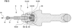
- Fig. 5 shows a feeler lever 6 of a 3D button 2 with a feeler insert 8, a coupling element 16, a coupling arm/measuring shaft 80 and an - alternative - screw insert 116.
- Fig. 6 shows this alternative screw insert 116 in detail.
- the key insert 8 and the coupling element 16 are identical to the version described above (according to the Figures 1 to 4 ) educated;
- the coupling arm/measuring shaft 80 and the screw insert 116 largely correspond to the design described above, especially as far as the rotary coupling of the coupling element 16 and screw insert 116 is concerned.
- the alternative screw insert 116 provides a radially resilient structure 148 on the outer surface 146 of the screw insert 116, which is formed there in the area of the first connection/coupling area 118.
- This axially resilient structure 148 is, in particular, like that Fig. 6 clarified, formed by means of - here three - spring clamping elements 150 ("clip").
- FIG. 5 shows, on the inner surface 92 of the recess 90 in the coupling arm/measuring shaft 80, in which the screw insert 116 is accommodated, there is a (locking) structure 94 - here in the form of a radially circumferential groove 96 on the inner surface 92 of the recess 90 in the coupling arm/measuring shaft 80 - formed, in which groove 96 this radially resilient structure 148 or the spring clamping elements 150 can snap into place.
- FIG. 7 and 8 show - in sectional views - versions of previously described coupling elements 16 (accommodated in the coupling arm/measuring shaft 80), which further create a tension by means of their surfaces in the coupling arm/measuring shaft 80 or in the recess 90 of the coupling arm/measuring shaft 80 (incidentally, these coupling elements 16, as well as the coupling arms/measuring shafts 80 that accommodate them, can or are designed according to the previously described designs).
- such coupling elements 16 have a section 38 whose outer circumference is non-round in cross section. As shown in FIGS. 7 and 8, this out-of-round shape is formed (in both cases) by regions 50, 52 located radially further inside and radially further out.
- This "non-round" portion 38 is on the respective coupling element 16 (according to Fig. 7 and Fig. 8 ) arranged between the planar system 36 and the pin 24a forming the first connection/coupling region 18 (cf. for example Fig. 2 ).
- Fig. 7 shows a coupling element 16 in which - to form the out-of-roundness or the regions 50, 52 located radially further inside and radially further outwards - the outer circumference of the partial region 38 has three interconnected "flatter” circular arcs 54 in cross section, ie, the radii of curvature of which are larger than half the diameter of the circle.
- Fig. 8 shows a similar coupling element 16, in which the outer circumference of the partial region 38 is three in cross section Circular arcs 54 (of a common circle, ie with the same radius) are connected via straight circular chords 56 in between.
- FIG. 7 shows a coupling arm/measuring shaft 80, the recess 90 on its inner surface 92 in cross section - (to the partial area 38 of the coupling element 16) being slightly larger - three interconnected "flatter” circular arcs 54 (so that - with a "concentric” arrangement/ Alignment of coupling arm/measuring shaft 80 and coupling element 16 - between coupling arm/measuring shaft 80 and coupling element 16 a game (necessary for the rotation (tension) forms/can form).
- Fig. 8 shows a coupling arm/measuring shaft 80, the recess 90 of which has three interconnected circular arcs 54 - three radii of equal circles with shifted centers - on its inner surface 92 in cross section (beginnings of the circular arcs 54 marked by circles K).
- the coupling element 16 if it is to be received in the coupling arm/measuring shaft 80, it can be inserted into its recess 90 and then - relative to the coupling arm/measuring shaft 80 - rotated.
- the radially further outer regions 50, 52 of the coupling element 16 or on/of the partial section 38 of the coupling element 16 then come into contact with the radially further inner regions 50, 52 of the coupling arm/measuring shaft 80 or in the recess 90 of the coupling arm/measuring shaft 80 or .
- the coupling element 16 and the coupling arm/measuring shaft 80 become tense.
- Fig. 9 shows a feeler lever 6 of a 3D button 2 with a feeler insert 8, a coupling element 16, an alternative (slightly modified) coupling arm/measuring shaft 80 and an alternative (slightly modified) screw insert 116.
- Fig. 10 shows a detail of this 3D button 2 with an alternative screw insert 116.
- Fig. 11 shows a cut - along the in Fig. 9 Cutting line marked FF on this 3D Button 2 with alternative screw insert 116.
- the key insert 8 and the coupling element 16 are identical to the version described above (according to the Figures 1 to 4 ) educated; the coupling arm/measuring shaft 80 and the screw insert 116 largely correspond to the version described above, especially as far as the rotary coupling of the coupling element 16 and screw insert 116 is concerned (thread segments 28, 126 (see Figs. 2 and 3)).
- the alternative screw insert 116 on the screw insert 116 - there at the other end of the recess 124 carrying the thread segments 126 or the internal thread portions 128 - provides a hole 152 forming the second connection/coupling region 120 with an inserted (hexagon socket) screw 122.
- the other end of the screw insert 116 which has the bore 152 and the screw 122, forms a radially extending contact surface 136 for the axial contact with the counter surface 144 on the coupling arm 80.
- the screw insert 116 here provides a substantially cylindrical section 138 for radial centering in the coupling arm 80.
- the radially extending contact surface 36 of the flange-like projection 42 of the coupling element 16 which extends radially outward and is directed in the direction of the pin 24a carrying the thread segments 28 or the external thread portions 30, is supported here on a counter surface 44 on the screw insert 116 (planar contact - see above) (cf. according to the design according to FIGS. 1 to 4, this flat contact 36/44 took place between the coupling element 16 and the coupling arm 80).
- a (further) flat contact between the screw insert 116 and the coupling arm 80 then takes place, as shown in FIGS. 9 and 10, via a flat contact surface 156 on the screw insert 116 and a counter surface 154 on the coupling arm 80.
- the screw insert 116 can be securely received and held in the coupling arm/measuring shaft 80 in a simple manner by means of these simple structural elements on the screw insert 116.
- elements of one exemplary embodiment can be combined with elements of another exemplary embodiment.
- the screw insert 116 can have a separate screw 122 (according to the design according to FIGS. 9 to 11) and contact surfaces 44/36 (according to the design according to Fig. 4 ) can be combined with each other on another feeler lever 6 of a 3D button 2.
- the screw insert 116 can also wobble slightly if the screw 122 is not fully tightened, so that the centering of the coupling arm 16 is not affected.
Landscapes
- Physics & Mathematics (AREA)
- General Physics & Mathematics (AREA)
- Engineering & Computer Science (AREA)
- Mechanical Engineering (AREA)
- Life Sciences & Earth Sciences (AREA)
- General Life Sciences & Earth Sciences (AREA)
- A Measuring Device Byusing Mechanical Method (AREA)
- Length Measuring Devices With Unspecified Measuring Means (AREA)
Description
- Die Erfindung wird durch die unabhängigen Ansprüche definiert, die Tastmessgeräte definieren.
- Die Erfindung betrifft ein Kupplungselement zur Aufnahme einer Tastspitze in einem Tastmessgerät, einen Schraubeinsatz zur Aufnahme einer Tastspitze in einem Tastmessgerät, eine Kupplungsanordnung für einen Tasteinsatz bei einem Tastmessgerät sowie ein bzw. Tastmessgeräte.
- Ein Tastmessgerät, beispielsweise ein Mehrkoordinaten-Tastmessgerät, kurz auch nur als 3D Taster bezeichnet, welches Abstandmessungen sowohl in Richtung einer Messachse als auch quer dazu erlaubt, ist beispielsweise aus der
WO 02/103282 A1 - Dieses Tastmessgerät umfasst ein Gehäuse, an dem ein Tasthebel, manchmal auch als Tastarm bezeichnet, in Richtung einer durch das Gehäuse definierten Messachse verschiebbar geführt ist. Der Tasthebel ist mittels eines Universalgelenks, beispielsweise hier bei der
WO 02/103282 A1 - Der Tasthebel hat einen aus dem Gehäuse herausragenden Tasteinsatz, kurz auch anschaulich oft als Tastspitze bezeichnet, dessen freies, durch eine Tastkugel gebildetes Tastende einen in der Ruhestellung des Tasthebels auf der Messachse liegenden Tast-Bezugspunkt definiert.
- Bezogen auf den Schwenkpunkt ragt ein Koppelarm des Tasthebels, auch als Messwelle des Tasthebels bezeichnet, entgegengesetzt zum Tasteinsatz in eine kreiszylindrische, zur Messachse zentrische Führungsöffnung des Gehäuses hinein.
- Über eine ein Zentrierelement und eine Gewindestange mit Außengewinde aufweisende Verschraubungsanordnung ist der Tasteinsatz, welcher neben der Tastkugel einen Stift, welcher die Tastkugel aufnimmt, und eine Hülse, welche ihrerseits mit dem Stift verbunden ist, aufweist, mit dem Koppelarm verschraubt.
- Dazu ist der Tasteinsatz, hier die Hülse des Tasteinsatzes, andererends der Tastkugel in einer entsprechenden Bohrung am in Richtung des Tasteinsatzes liegenden Ende des Zentrierelements gehalten. Das Zentrierelement weist andererends dieses Bohrungsendes ein Innengewinde auf, welches mit der Gewindestange bzw. mit dem Außengewinde der Gewindestange verschraubt ist. Am dem Tasteinsatz abgewandten Ende der Gewindestange ist diese - über ein Außengewinde an der Gewindestange - in einem Innengewinde des Koppelarms verschraubt.
- Eine an dem Gehäuse gehaltene Messuhr erfasst die Position der Messwelle bzw. des Tasthebels relativ zu dem Gehäuse.
- Durch unsachgemäßen Gebrauch eines solchen Tastmessgeräts im Einsatz kann der Tasteinsatz beschädigt werden, beispielsweise im Bereich der aus Keramik bestehenden und als Sollbruchstelle dienenden (Keramik-)Hülse des Tasteinsatzes brechen. Ein Ersatz bzw. Austausch des Tasteinsatzes ist dann nötig.
- Es ist Aufgabe der Erfindung, eine einfache, kostengünstige und schnell wechselbare Kopplung eines Tasteinsatzes in dem Tastmessgerät zu schaffen.
- Diese Aufgabe wird gelöst durch ein Kupplungselement zur Aufnahme einer Tastspitze in einem Tastmessgerät, einen Schraubeinsatz zur Aufnahme einer Tastspitze in einem Tastmessgerät, eine Kupplungsanordnung für einen Tasteinsatz bei einem Tastmessgerät sowie ein bzw. Tastmessgeräte mit den Merkmalen des jeweiligen unabhängigen Anspruchs. Vorteilhafte Weiterbildungen der Erfindung sind Gegenstand abhängiger Ansprüche sowie der nachfolgenden Beschreibung.
- Verwendete Begriffe, wie axial und radial, sind - soweit nicht anders explizit definiert - in Bezug auf eine Messachse eines die erfindungsgemäßen Gegenstände aufweisenden Tastmessgeräts zu verstehen.
- Das erfindungsgemäße Kupplungselement weist einerends einen einen ersten Verbindungs-/Kopplungsbereich ausbildenden Zapfen auf.
- Dieser Zapfen bildet auf einer äußeren Oberfläche mehrere sich in radialer Umfangsrichtung nicht aneinander anschließende Gewindesegmente aus.
- (Auch) Der erfindungsgemäße Schraubeinsatz weist einerends einen ersten Verbindungs-/Kopplungsbereich auf, insbesondere zur Verbindung mit dem Kupplungselement, - mit einer Ausnehmung, auf deren inneren Oberfläche (ebenfalls) mehrere sich in radialer Umfangsrichtung nicht aneinander anschließende Gewindesegmente ausgebildet sind.
- Ein (solches) Gewindesegment (- sei es bei dem Kupplungselement oder bei dem Schraubeinsatz -) kann dabei durch eine oder mehrere jeweils einen Teil eines Gewindegangs (Teilgewindegang) ausbildende Vertiefungen gebildet werden (, wobei dann eine solche Vertiefung bzw. einen solchen Teilgewindegang begrenzende "Erhebungen" als Gewindeflanken gesehen - und als solche bezeichnet werden mögen).
- Vereinfacht ausgedrückt, - in radialer Umfangsrichtung - zwischen den Gewindesegmenten sind (auf der äußeren Zapfenoberfläche (bei dem Kupplungselement) oder der inneren Ausnehmungsoberfläche (bei dem Schraubeinsatz)) gewindefreie Bereiche bzw. gewindefreie Abschnitte, im Folgenden kurz und vereinfacht als Unterbrechungen bezeichnet, beispielsweise im Wesentliche glatten Teilzylinderoberflächen/-mäntel, ausgebildet.
- D.h., anschaulich gesehen, auf der Zapfenoberfläche bzw. inneren Oberfläche der Ausnehmung wechseln sich in radialer Umfangsrichtung die Gewindesegmente (beim Zapfen des Kupplungselements anschaulich gesehen Außengewindesegmente bzw. in der inneren Ausnehmung des Schraubeinsatzes anschaulich gesehen Innengewindesegmente) und die gewindefreien Bereiche bzw. Unterbrechungen ab.
- Dieses erweist sich dahingehend als vorteilhaft, kann dadurch ein entsprechendes Gegenstück zum Kupplungselement bzw. zum Schraubeinsatz, beispielsweise der Schraubeinsatz zum Kupplungselement bzw. vice versa, einfach und schnell mit diesem bzw. dieser gekoppelt werden, beispielsweise durch (schnelles) Drehkuppeln, d.h., durch axiales Auf-/Einstecken und dann (Ver-)Drehen.
- Hierbei "tauchen" dann - beim axialen Auf-/Einstecken - die Gewindesegmente des einen Elements, beispielsweise des Kupplungselements bzw. die Außengewindesegmente des Kupplungselements, in die Unterbrechungen des anderen Elements (Gegenelement), beispielsweise des Schraubeinsatzes, ein (bzw. vice versa, d.h., die Innengewindesegmente des Gegenelements, beispielsweise des Schraubeinsatzes, tauchen in die Unterbrechungen des Elements, beispielsweise des Kupplungselements, ein) - bis sie dann gegeneinander verdreht werden - wobei dann Außengewindesegmente und Innengewindesegmente ineinander greifen.
- Kurz, Kupplungselement und Schraubeinsatz können - durch dieses Dreh-Kuppeln - auf einfache Art und Weise schnell gekoppelt - und miteinander präzise verspannt werden. Die Verbindung - und so die Vorteile des Kupplungselements und/oder Schraubeisatzes - erweist sich als stabiler, besser, insbesondere schneller und spielfrei, zentrierend.
- Zweckmäßig ist es hier weiter, wenn die Unterbrechungen - zwischen den Gewindesegmenten - radial gegenüber den Gewindesegmenten zurückgesetzt sind. Anschaulich ausgedrückt, die die Unterbrechungen - zwischen den Gewindesegmenten - liegen - bei dem Kupplungselement - radial weiter innen als die Gewindesegmente bzw. liegen - bei dem Schraubeinsatz - radial weiter außen als die Gewindesegmente. Das axiale Einstecken (von Element und Gegenelement) bzw. "Eintauchen" (der Gewindesegmente in die Unterbrechungen) kann einfacher erfolgen.
- Dieses Drehkuppeln kann auch dadurch weiter vereinfacht werden, wenn die Gewindesegmente des einen Elements, beispielsweise des Kupplungselements, und die Unterbrechungen des Gegenelements, beispielsweise des Schraubeinsatzes, insbesondere in ihrer Erstreckung in Umfangsrichtung aneinander angepasst sind. D.h., ist die Erstreckung in Umfangsrichtung der Gewindesegmente (des einen Elements) gleich oder insbesondere kleiner als die Umfangsrichtungserstreckung der Unterbrechungen (des Gegenelements), so können Element und Gegenelement leichter axial gegeneinander verschoben werden bzw. ineinander eintauchen.
- Insbesondere zweckmäßig ist es auch, (- sei es bei dem Kupplungselement oder bei dem Schraubeinsatz -) wenn die Steigungsverläufe bei allen die Teilgewindegänge ausbildenden Vertiefungen gleich sind.
- Dadurch lässt sich ein klemmungsfreies Kuppeln des Kupplungselements bzw. des Schraubeinsatzes mit einem entsprechenden Gegenstück, beispielsweise von dem Kupplungselement und dem Schraubeinsatz, ermöglichen.
- Vereinfacht bzw. anschaulich ausgedrückt/erklärt, durch gleiche Steigungsverläufe stellt sich an/bei jedem Teilgewindegang derselbe "Hub" ein. Unterschiedliche Hübe können andernfalls zu Klemmungen führen bzw. ein Kuppeln des Kupplungselements bzw. des Schraubeinsatzes mit einem entsprechenden Gegenstück erschweren.
- Dabei können aber die - gleichen - Steigungsverläufe selbst wiederum jeweils konstant sein - oder sich ändern, insbesondere degressiv sein.
- Insbesondere die degressive Ausgestaltung eines Teilgewindegangs ermöglicht ein (anfänglich) schnelles Greifen bei einer Kopplung des Kupplungselements bzw. des Schraubeinsatzes mit einem entsprechenden Gegenstück, wie beispielsweise beim Drehkuppeln (s. oben).
- Darüber hinaus kann auch vorgesehen sein, dass (- sei es bei dem Kupplungselement oder bei dem Schraubeinsatz -) die die Teilgewindegänge ausbildenden Vertiefungen so ausgebildet sind, dass sie keinen gemeinsamen Gewindegang ausbilden. D.h., anschaulich oder vereinfacht ausgedrückt, alle Vertiefungen bzw. Teilgewindegänge liegen nicht auf einer (gedacht durchgängigen) gemeinsamen Schraubenlinie.
- Ferner kann es (- sei es bei dem Kupplungselement oder bei dem Schraubeinsatz -) auch zweckmäßig sein, dass zwischen den Teilgewindegängen eines Gewindesegments Lücken ausgebildet sind.
- Anschaulich bzw. vereinfacht ausgedrückt, Teilgewindegänge eines Gewindesegments grenzen in axialer Richtung nicht unmittelbar aneinander, sondern zwischen jeweils zwei Teilgewindegänge sind jeweils breitere Vertiefungen als die Teilgewindegänge selbst.
- Dadurch können - bei Kopplung des Kupplungselements bzw. des Schraubeinsatzes mit einem entsprechenden Gegenstück - das Außengewinde beim Kupplungselement bzw. das Innengewinde bei dem Schraubeinsatz mit dem entsprechenden Innengewinde bzw. dem entsprechenden Außengewinde des Gegenstücks leichter ineinander finden.
- Insbesondere herstellungstechnisch günstig ist es, wenn (-sei es bei dem Kupplungselement oder bei dem Schraubeinsatz-) mindestens zwei oder mehrere, insbesondere alle, Gewindesegmente gleich ausgebildet sind.
- Bevorzugt kann auch vorgesehen sein, dass auf der äußeren Oberfläche des Zapfens bzw. auf der inneren Oberfläche der Ausnehmung drei, insbesondere gleichmäßig in radialer Umfangsrichtung verteilte, Gewindesegmente angeordnet sind. Auch vier oder noch mehr, insbesondere gleichmäßig in radialer Umfangsrichtung verteilte, Gewindesegmente können vorgesehen sein.
- Vorzugsweise können diese Gewindesegmente auch gleichwinklig angeordnet sein.
- Entsprechendes kann dann so auch für die Unterbrechungen am Zapfen bzw. auf der inneren Oberfläche der Ausnehmung gelten.
- Darüber hinaus kann auch vorgesehen sein, dass in dem den ersten Verbindungs-/Kopplungsbereich ausbildenden Zapfen des Kupplungselements eine ein Innengewinde aufweisenden Ausnehmung vorgesehen ist.
- Diese kann beispielsweise dazu vorgesehen sein, das Kupplungselements - anstelle über die Gewindesegmente auf der Zapfenoberfläche - mit einem anderen, alternativen Gegenstück, beispielsweise eine Gewindestange, wie sie beispielsweise der 3D Taster aus der
WO 02/103282 A1 - Ferner kann am Kupplungselement - dort andererends - ein einen zweiten Verbindungs-/Kopplungsbereich ausbildender weiterer Zapfen vorgesehen sein. Auch dieser weitere Zapfen kann mit einer weiteren Ausnehmung ausgebildet sein. Diese weitere Ausnehmung kann beispielsweise dazu dienen, eine Tastspitze/einen Tasteinsatz aufzunehmen. Beispielsweise kann dieser/diese darin verschraubt und/oder verklebt sein.
- So kann beispielsweise vorgesehen sein, eine Hülse eines Tasteinsatzes in dieser weiteren Ausnehmung zu verkleben.
- Auch ist es zweckmäßig, eine sich radial erstreckende Anlagefläche für eine axiale Plananlage an bzw. bei dem Kupplungselement vorzusehen (kurz auch nur Plananlage). Diese kann insbesondere in Richtung des Zapfenendes des den ersten Verbindungs-/Kopplungsbereich ausbildende Zapfens ausgerichtet sein - und insbesondere auch dazu vorgesehen sein, auf einer entsprechenden Fläche an einem Koppelarm/einer Messwelle aufzuliegen.
- Auch kann das Kupplungselement einen im Wesentlichen zylindrischen Teilabschnitt aufweisen, auf dessen äußeren Oberfläche ein in radialer Umfangsrichtung zumindest teilweise, insbesondere vollständig, umlaufender, sich radial nach außen gewölbter Wulst für eine radiale Zentrierung ausgebildet sein (kurz auch nur Zentrierung, beispielsweise für eine Zentrierung des Kupplungselements in einer Ausnehmung im Koppelarm/Messwelle, in welcher Ausnehmung das Kupplungselement ausgenommen ist/wird).
- Dieser Wulst kann insbesondere nach dem den ersten Verbindungs-/Kopplungsbereich ausbildenden Zapfen auf der äußeren Oberfläche des Zapfens ausgebildet sein, insbesondere zwischen Plananlage und dem den ersten Verbindungs-/Kopplungsbereich ausbildenden Zapfen.
- Weiterhin kann auch vorgesehen sein, dass das Kupplungselement einen Teilabschnitt vorsieht, dessen äußerer Umfang im Querschnitt unrund ist. Dieses Unrund kann insbesondere durch radial weiter innen und radial weiter außenliegende Bereiche gebildet werden.
- Dabei können als "unrund" geometrische Formen und Querschnitte angesehen werden, die vom Kreis abweichen.
- Dementsprechend ist es auch zweckmäßig, wenn eine innere Oberfläche einer Ausnehmung im Koppelarm/Messwelle, in welcher das Kupplungselement aufgenommen werden kann bzw. ist/wird, komplementär zum Unrund ausgebildet ist, insbesondere auch radial weiter innen und radial weiter außenliegende Bereiche aufweist.
- Somit kann dann, soll das Kupplungselement im Koppelarm/Messwelle aufgenommen werden, dieses in dessen Ausnehmung eingeschoben und dann - gegenüber der Koppelarm/Messwelle - verdreht werden. Kommen dabei dann die radial weiter außenliegenden Bereiche des Kupplungselements bzw. am/des Teilabschnitts des Kupplungselements mit den radial weiter innenliegenden Bereichen des Koppelarms/Messwelle bzw. in der Ausnehmung des Koppelarms/Messwelle bzw. an der inneren Oberfläche der Ausnehmung des Koppelarms/Messwelle zur Anlage, so verspannen sich das Kupplungselement und der Kopplungsarm/Messwelle (d.h., das Spiel wird aus der Paarung genommen) - und können dadurch auch zueinander zentriert werden.
- Vorteilhaft kann es auch sein, wenn der Schraubeinsatz andererends einen einen zweiten Verbindungs-/Kopplungsbereich ausbildenden Zapfen aufweist, auf dessen äußeren Oberfläche ein Außengewinde ausgebildet ist, oder wenn der Schraubeneinsatz andererends eine den zweiten Verbindungs-/Kopplungsbereich 120 ausbildende Bohrung mit eingesetzter (Innensechskant-)Schraube aufweist.
- Mittels dieses Außengewindes bzw. dieser Schraube bzw. dessen (Außen-)Gewinde kann beispielsweise der Schraubeinsatz mit einem bei dem Koppelarm vorgesehenen Innengewinde mit diesem verschraubt werden.
- Auch kann bei dem Schraubeinsatz ein durchmesserverjüngter, im Wesentlichen zylindrischer Zwischenbereich zwischen dem ersten und dem zweiten Verbindungs-/Kopplungsbereich, vorgesehen sein. Durch diesen kann der Schraubeinsatz gewisse Flexibilität aufweisen, - um gegebenenfalls auftretende Toleranzen ausgleichen zu können.
- Auch eine axiale Plananlage und/oder eine Zentrierung kann bei dem Schraubeinsatz vorgesehen sein. D.h., anders ausgedrückt, es kann vorgesehen sein, dass der Schraubeinsatz eine sich radial erstreckende Anlagefläche für eine axiale Plananlage bzw. einen im Wesentlichen zylindrischen Teilabschnitt für eine radiale Zentrierung (beispielsweise für eine Zentrierung des Schraubeinsatzes in einer Ausnehmung im Koppelarm/Messwelle, in welcher Ausnehmung der Schraubeinsatz) aufweist - beides insbesondere zur Anlage und/oder Zentrierung gegenüber der Messwelle/dem Koppelarm.
- Weiterbildend kann auch eine radial federnde Struktur auf einer äußeren Oberfläche des Schraubeinsatzes vorgesehen sein, insbesondere im Bereich des ersten Verbindungs-/Kopplungsbereichs.
- Zweckmäßig, weil fertigungstechnisch einfach, kann hier weiter sein, wenn die axial federnde Struktur mittels Federklemmelemente ausgebildet ist ("Clip").
- Dementsprechend kann es dann auch zweckmäßig sein, wenn an einer inneren Oberfläche einer Ausnehmung im Koppelarm/Messwelle, in welcher der Schraubeinsatz aufgenommen werden kann bzw. ist/wird, eine (Einrast-)Struktur ausgebildet ist, in welcher diese radial federnde Struktur am/des Schraubeinsatzes einrastbar ist.
- Zweckmäßig, weil fertigungstechnisch einfach, kann hier weiter sein, wenn die (Einrast-)Struktur durch eine radial umlaufende Nut an der inneren Oberfläche der Ausnehmung im Koppelarm/Messwelle ausgebildet ist.
- Mittels dieser einfachen Strukturelemente - von axial federnder Struktur des Schraubeinsatzes und/oder (Einrast-)Struktur des Koppelarms/Messwelle - kann so der Schraubeinsatz auf einfache Art und Weise sicher im Koppelarm/Messwelle aufgenommen und gehalten werden.
- Gegebenenfalls ist es auch zweckmäßig hier den Schraubeinsatz mit einer Verdrehsicherung gegenüber dem Koppelarm/Messwelle) auszubilden.
- Die erfindungsgemäße Kupplungsanordnung sieht das Kupplungselement sowie den Schraubeinsatz vor. Beide können insbesondere mit den beschriebenen Ausgestaltungen ausgebildet sein.
- Besondern zweckmäßig ist es hier, wenn die Gewindesegmente des Kupplungselements und die Gewindesegmente des Schraubeinsatzes als korrespondierende, verschraubbare Innen-/Außengewinde ausgebildet sind (s. oben zum Drehkuppeln)).
- Auch die jeweiligen Unterbrechungen beim Kupplungselement und Schraubeinsatz können aneinander angepasst sein (s. oben zum Drehkuppeln).
- Die Verbindung von Kupplungselement und Schraubeinsatz erfolgt dann insbesondere durch - schnelles - Drehkuppeln (s. oben), d.h., durch axiales Einstecken des Kupplungselements in den Schraubeinsatz und dann - gegenseitiges - (Ver-) Drehen.
- Besonderes zweckmäßig ist es so auch, das Kupplungselement und/oder den Schraubeinsatz bzw. die Kupplungsanordnung zur Aufnahme einer Tastspitze in einem Tastmessgerät, insbesondere einem 3D-Taster, zu verwenden, kann so die Tastspitze einfach und schnell (im Tastmessgerät) montiert oder (bei diesem) ausgetauscht werden.
- Ein erfindungsgemäßes Tastmessgerät sieht (zumindest) den Schraubeinsatz, insbesondere nach beschriebenen Ausgestaltungen, und einen Koppelarm/Messwelle vor, wobei der Schraubeinsatz und der Koppelarm/Messwelle miteinander verbunden sind, insbesondere miteinander verschraubt oder einstückig ausgebildet sind.
- Insbesondere kann diese Verbindung von Schraubeinsatz und Koppelarm/Messwelle dadurch realisiert sein, dass Schraubeinsatz andererends den den zweiten Verbindungs-/Kopplungsbereich ausbildenden Zapfen aufweist, auf dessen äußeren Oberfläche das Außengewinde ausgebildet ist, und der Koppelarm das vorgesehene Innengewinde vorsieht. Das Außengewinde des Schraubeinsatzes und das Innengewinde des Koppelarm können dann miteinander verschraubt werden.
- Ein weiteres erfindungsgemäßes Tastmessgerät kann auch das Kupplungselement, insbesondere nach beschriebenen Ausgestaltungen, einen Schraubeinsatz, insbesondere nach beschriebenen Ausgestaltungen, einem Tasteinsatz, insbesondere einen eine Tastkugel, einen Stift sowie eine Hülse aufweisenden Tasteinsatz, und einen Koppelarm/Messwelle aufweisen, wobei der Tasteinsatz mittels des Kupplungselements und des mit dem Kupplungselement verbundenen Schraubeinsatzes mit dem Koppelarm/Messwelle verbunden ist.
- Weiter kann bei dem Tastmessgerät auch vorgesehen sein, dass die Gewindesegmente des Kupplungselements und die Gewindesegmente des Schraubeinsatzes als korrespondierende, verschraubbare Innen-/Außengewinde ausgebildet sind.
- Auch die jeweiligen Unterbrechungen können aneinander angepasst sein, so dass sich das Kupplungselement und der Schraubeinsatz durch Drehkuppeln (s. oben) miteinander verbinden lassen.
- Alternativ zu dem die Gewindesegmente aufweisenden erfindungsgemäßen Kupplungselement, kann auch ein (weiteres) solches vorgesehen sein, welches einerends einen einen ersten Verbindungs-/Kopplungsbereich ausbildenden Zapfen aufweist, auf dessen äußerer Oberfläche (anstelle der (mehreren durch die Unterbrechungen beabstandeten) Gewindesegmente) ein (durchgängiges bzw. nicht unterbrochenes) mehrgängiges Außengewinde ausgebildet ist.
- Auch dieses alternative Kupplungselement kann mit beschriebenen Weiterbildungen des vorbeschriebenen, die Gewindesegmente ausweisenden, Kupplungselement weitergebildet sein, wie insbesondere die Ausnehmung mit Innengewinde bzw. die weitere Ausnehmung mit dem weiteren Innengewinde, die Plananlage bzw. die Zentrierung.
- Vorteilhaft bei diesem das mehrgängige Gewinde aufweisende alternative Kupplungselement ist insbesondere, dass mit einem solchen, wird es über dieses mehrgängige Gewinde verschraubt, beispielsweise in einem Tastmessgerät, ein größerer axialer Vorschub/Hub bei gleichem Drehwinkel (im Vergleich zu eingängigen Gewinden) realisieren lässt, wodurch sich dieses Kupplungselement - schneller als ein herkömmliches eingängiges Gewinde aufweisende Teil - verschrauben lässt.
- Erfolgt die Verbindung eines Tasteinsatzes dann über ein solches das mehrgängige Gewinde aufweisende alternative Kupplungselement bei/in einem Tastmessgerät, lässt sich so ein Tasteinsatz in schneller(-er) Zeit wechseln bzw. austauschen.
- Die bisher gegebene Beschreibung vorteilhafter Ausgestaltungen der Erfindung enthält zahlreiche Merkmale, die in den einzelnen Unteransprüchen teilweise zu mehreren zusammengefasst wiedergegeben sind. Diese Merkmale können jedoch zweckmäßigerweise auch einzeln betrachtet und zu sinnvollen weiteren Kombinationen zusammengefasst werden.
- Auch wenn in der Beschreibung bzw. in den Patentansprüchen einige Begriffe jeweils im Singular oder in Verbindung mit einem Zahlwort verwendet werden, soll der Umfang der Erfindung für diese Begriffe nicht auf den Singular oder das jeweilige Zahlwort eingeschränkt sein. Ferner sind die Wörter "ein" bzw. "eine" nicht als Zahlwörter, sondern als unbestimmte Artikel zu verstehen.
- Die oben beschriebenen Eigenschaften, Merkmale und Vorteile der Erfindung sowie die Art und Weise, wie diese erreicht werden, werden klarer und deutlicher verständlich im Zusammenhang mit der folgenden Beschreibung der Ausführungsbeispiele der Erfindung, die im Zusammenhang mit der bzw. den Zeichnungen/Figuren näher erläutert wird/werden (gleiche Bauteile/Komponenten und Funktionen weisen in den Zeichnungen/Figuren gleiche Bezugszeichen auf).
- Die Ausführungsbeispiele dienen der Erläuterung der Erfindung und beschränken die Erfindung nicht auf darin angegebene Kombinationen von Merkmalen, auch nicht in Bezug auf funktionale Merkmale. Außerdem können dazu geeignete Merkmale eines jeden Ausführungsbeispiels auch explizit isoliert betrachtet, aus einem Ausführungsbeispiel entfernt, in ein anderes Ausführungsbeispiel zu dessen Ergänzung eingebracht und/oder mit einem beliebigen der Ansprüche kombiniert werden.
- Es zeigen:
- FIG 1
- einen Tasthebel mit einem Tasteinsatz, einem Kupplungselement, einem Schraubeinsatz und einem Koppelarm/Messwelle eines Tastmessgeräts gemäß einer Ausführung der Erfindung;
- FIG 2
- (in Ansichten 2-1, 2-2 und 2-3) ein Kupplungselement eines Tasthebels eines Tastmessgeräts gemäß einer Ausführung der Erfindung
- FIG 3
- (in Ansichten 3-1, 3-2 und 3-3) einen Schraubeinsatz eines Tasthebels eines Tastmessgeräts gemäß einer Ausführung der Erfindung;
- FIG 4
- einen Abschnitt eines Tasthebels mit einem Tasteinsatz, einem Kupplungselement, einem Schraubeinsatz und einem Koppelarm/Messwelle eines Tastmessgeräts gemäß einer Ausführung der Erfindung;
- FIG 5
- einen Tasthebel mit einem Tasteinsatz, einem Kupplungselement, einem Schraubeinsatz und einem Koppelarm/Messwelle eines Tastmessgeräts gemäß einer weiteren Ausführung der Erfindung;
- FIG 6
- (in Ansichten 6-1, 6-2 und 6-3) einen Schraubeinsatz eines Tasthebels eines Tastmessgeräts gemäß einer weiteren Ausführung der Erfindung;
- FIG 7
- einen Schnitt bei einem Tasthebel mit verspannbaren Kupplungselement eines Tastmessgeräts gemäß einer wieder weiteren Ausführung der Erfindung;
- FIG 8
- einen Schnitt bei einem Tasthebel mit verspannbaren Kupplungselement eines Tastmessgeräts gemäß einer wieder weiteren Ausführung der Erfindung;
- FIG 9
- einen Tasthebel mit einem Tasteinsatz, einem Kupplungselement, einem Schraubeinsatz und einem Koppelarm/Messwelle eines Tastmessgeräts gemäß einer noch weiteren Ausführung der Erfindung;
- FIG 10
- eine Detailansicht von dem Kupplungselement, dem Schraubeinsatz und dem Koppelarm/Messwelle des Tastmessgeräts gemäß der noch weiteren Ausführung der Erfindung;
- FIG 11
- einen Schnitt bei dem Tastmessgerät, wie in
FIG 9 gekennzeichnet, gemäß der noch weiteren Ausführung der Erfindung. - Hier verwendete Begriffe, wie axial und radial, sind - soweit nicht anders explizit definiert - in Bezug auf die Messachse 82 des 3D Tasters 2 zu verstehen.
- Der 3D Taster 2 umfasst ein Gehäuse 4 (in den Figuren nicht dargestellt), an dem ein Tasthebel 6 (vgl.
Fig. 1 ,Fig. 4 ) in Richtung einer durch das Gehäuse 4 definierten Messachse 82 verschiebbar geführt ist. - Der Tasthebel 6 ist mittels eines Universalgelenks 86, hier in Form eines Kugelgelenks 86, darüber hinaus um einen auf der Messachse 82 liegenden Schwenkpunkt allseitig schwenkbar an dem Gehäuse 4 geführt und wird von einer Rückstellfeder (nicht in den Figuren dargestellt) federnd vorgespannt.
- Der Tasthebel 6 hat, wie die
Figuren 1 und4 zeigen, einen aus dem Gehäuse herausragenden Tasteinsatz/Tastspitze 8, dessen freies, durch eine Tastkugel 10 gebildetes Tastende einen in der Ruhestellung des Tasthebels 6 auf der Messachse 82 liegenden Tast-Bezugspunkt definiert. - Der Tasthebel 6 umfasst, wie die
Figuren 1 und4 verdeutlichen, darüber hinaus einen Koppelarm 80, welcher - bezogen auf den Schwenkpunkt - entgegengesetzt zum Tasteinsatz 8 bzw. entgegengesetzt der Richtung 84 zur Tastspitze 8 in eine kreiszylindrische, zur Messachse 82 zentrische Führungsöffnung des Gehäuses 4 hineinragt (nicht in den Figuren dargestellt) . - Über eine ein Kupplungselement 16 (vgl.
Fig. 2 ) und einen mit dem Kupplungselement 16 verbundenen Schraubeinsatz 116 (vgl.Fig. 3 ) aufweisende Kupplungsanordnung 216 ist, wie dieFiguren 1 und4 verdeutlichen, der Tasteinsatz 8, welcher neben der Tastkugel 10 einen (Stahl-)Stift 12, welcher die Tastkugel 10 mittels einer Schweißverbindung, aufnimmt, und eine (Keramik-)Hülse 14, welche ihrerseits mit dem Stift 12 verbunden ist, aufweist, mit dem Koppelarm 80 verschraubt. - Dazu sieht, wie näher im Zusammenhang mit
Fig. 2 beschrieben wird, das (montierte) Kupplungselement 16 (dann) an ihrem in Richtung 84 zur Tastspitze 8 zeigendem Ende eine Ausnehmung 26b, in Form einer axialen, einseitig (endseitig) offenen Bohrung, vor, welche dazu dient, die Hülse 14 des Tasteinsatzes 8 aufzunehmen. - Wie
Fig. 2 (in Ansichten 2-1, 2-2, 2 -3, Detailansicht des Kupplungselements 16) zeigt, weist das Kupplungselement 16 einerends einen einen ersten Verbindungs-/Kopplungsbereich 18 ausbildenden Zapfen 24a auf. - Dieser Zapfen 24a bildet auf einer äußeren Oberfläche 60 mehrere, in diesem Fall drei, sich in radialer Umfangsrichtung 62 nicht aneinander anschließende, in radialer Umfangsrichtung 62 gleichmäßig verteilt angeordnete und an sich gleiche Gewindesegmente 28 in Form von Außengewindeanteilen 30 aus, deren Teilgewindegänge 30 alle den gleichen, leicht degressiven Steigungsverlauf 68 bzw. kurz die gleiche, leicht degressive Steigung 68 aufweisen.
- D.h., in radialer Umfangsrichtung 62 sind, wie
Fig. 2 zeigt,-zwischen den drei Gewindesegmenten 28 (auf der äußeren Zapfenoberfläche 60 bei dem Kupplungselement 16) drei - so ebenfalls gleichmäßig in radialer Umfangsrichtung 62 (sich mit den Gewindesegmenten 28 abwechselnd) verteilt angeordnete, gewindefreie Bereiche bzw. gewindefreie Abschnitte, im Folgenden kurz und vereinfacht als Unterbrechungen 32 bezeichnet, hier in Form glatter Teilzylinderoberflächen/-mäntel, ausgebildet. - Dabei sind, wie
Fig. 2 auch erkennen lässt, die drei Unterbrechungen 32 in radialer Umfangsrichtung 62 jeweils etwas länger als die drei Gewindesegmente 28 - und, wieFig. 2 auch verdeutlicht, radial weiter innen liegend bzw. radial zurückgesetzt ausgebildet als die Gewindesegmente 28. - Weiterhin weist, wie
Fig. 2 zeigt, der die Außengewindeanteile 30 tragende Zapfen 24a des Kupplungselements 16 eine axiale Ausnehmung 26a, in Form einer axialen, einseitig (endseitig) offenen Bohrung, auf, in welcher ein Innengewinde 34 vorgesehen ist. - Ferner ist, wie
Fig. 2 verdeutlicht, am Kupplungselement 16 - dort andererends des die Gewindesegmente 28 bzw. die Außengewindeanteile 30 tragenden Zapfens 24a - ein einen zweiten Verbindungs-/Kopplungsbereich 20 ausbildender weiterer Zapfen 24b vorgesehen. - Auch dieser weitere Zapfen 24b sieht eine Ausnehmung 26b, in Form einer axialen, einseitig (endseitig) offenen Bohrung, vor, welche dazu dient (, wie Fig.en 1 und 4 zeigen), die Hülse 14 des Tasteinsatzes 8 aufzunehmen. D.h., die Hülse 14 des Tasteinsatzes 8 ist in dieser Ausnehmung 26b verklebt.
- Ferner ist, wie
Fig. 2 zeigt, an dem Kupplungselement 16 eine sich radial erstreckende, in Richtung des die Gewindesegmente 28 bzw. die Außengewindeanteile 30 tragenden Zapfens 24a gerichtete Anlagefläche 36 - an einem sich radial nach außen erstreckenden flanschartigen Vorsprung 42 - für eine axiale Plananlage an einer Gegenfläche 44 an dem Koppelarm 80 vorgesehen (kurz auch nur Plananlage). - Der flanschartige Vorsprung 42 sieht, wie
Fig. 2 auch zeigt, auf seiner Außenumfangsfläche eine Riffelung 46 zur besseren Greifbarkeit vor. Eine entsprechende Riffelung 48 ist auch am Außenumfang des weiteren Zapfens 24b (dort auch zur besseren Greifbarkeit) ausgebildet. - Weiterhin sieht das Kupplungselement 16 - axial zwischen dem die Gewindesegmente 28 bzw. die Außengewindeanteile 30 tragenden Zapfen 24a und dem flanschartigen, die Plananlage vorsehenden Vorsprung 42 - einen im Wesentlichen zylindrischen Teilabschnitt 38 vor, auf dessen äußeren Oberfläche ein in radialer Umfangsrichtung umlaufender, sich radial nach außen gewölbter Wulst 40 für eine radiale Zentrierung des Kupplungselements 16 in dem Koppelarm 80 (vgl. Fig.en 1 und 4) ausgebildet ist (kurz auch nur Zentrierung).
-
Fig. 3 zeigt (in Ansichten 3-1, 3-2, 3 -3) im Detail den Schraubeinsatz 116. - Wie
Fig. 3 zeigt, sieht der Schraubeinsatz 116 einerends einen ebenfalls einen ersten Verbindungs-/Kopplungsbereich 118 auf. - Dieser ersten Verbindungs-/Kopplungsbereich 118 weist eine axiale Ausnehmung 124, in Form einer axialen, einseitig (endseitig) offenen Bohrung, auf, auf deren inneren Oberfläche 70 mehrere, in diesem Fall drei, sich in radialer Umfangsrichtung 62 nicht aneinander anschließende, in radialer Umfangsrichtung 62 gleichmäßig verteilt angeordnete und an sich gleiche Gewindesegmente 126 in Form von Innengewindeanteilen 128 ausgebildet sind, deren Teilgewindegänge 128 alle den gleichen, leicht degressiven Steigungsverlauf 68 bzw. kurz die gleiche, leicht degressive Steigung 68 aufweisen.
- D.h., in radialer Umfangsrichtung 62 sind, wie
Fig. 3 zeigt,-zwischen den drei Gewindesegmenten 126 (auf der inneren Ausnehmungsoberfläche 70 bei dem Schraubeinsatz 116) drei - so ebenfalls gleichmäßig in radialer Umfangsrichtung 62 (sich mit den Gewindesegmenten 126 abwechselnd) verteilt angeordnete, gewindefreie Bereiche bzw. gewindefreie Abschnitte, im Folgenden kurz und vereinfacht wieder als Unterbrechungen 130 bezeichnet, hier in Form glatter Teilzylinderoberflächen/- mäntel, ausgebildet. - Dabei sind, wie
Fig. 3 auch erkennen lässt, die drei Unterbrechungen 130 in radialer Umfangsrichtung 62 jeweils etwas länger als die drei Gewindesegmente 126 - und, wieFig. 3 auch verdeutlicht, radial weiter außenliegend bzw. radial gegenüber den Gewindesegmenten 126 zurückgesetzt. - Kurz, der erste Verbindungs-/Kopplungsbereich 118 des Schraubeinsatzes 116 ist als komplementäres, kuppelbares Gegenstück/-element zum ersten Verbindungs-/Kopplungsbereich 18 des Kupplungselements 16 - oder - die die Gewindesegmente 126 tragenden Ausnehmung 124 des Schraubeinsatzes 116 ist als komplementäres, kuppelbares Gegenstück/-element zum die Gewindesegmente 28 tragenden Zapfen 24a des Kupplungselements 16 ausgebildet.
- Über diese komplementären Elemente lassen sich, wie zu beschreiben sein wird, das Kupplungselement 16 und der Schraubeinsatz 116 auf einfache und schnelle Weise - durch Dreh-Kuppeln - miteinander verbinden.
- Ferner ist, wie
Fig. 3 verdeutlicht, am Schraubeinsatz 116 - dort andererends der die Gewindesegmente 126 bzw. die Innengewindeanteile 128 tragenden Ausnehmung 124 - ein einen zweiten Verbindungs-/Kopplungsbereich 120 ausbildender Zapfen 122 vorgesehen. - Auf der äußeren Oberfläche 140 des Zapfens 122 ist ein Außengewinde 134 vorgesehen, über welches der Schraubeinsatz 116 im Koppelarm 80 (dort in einem Innengewinde 88) verschraubbar ist (vgl. Fig.en 1 und 4).
- Ferner ist, wie
Fig. 3 zeigt (undFig.4 verdeutlicht), - ähnlich dem Kupplungselement 16 - an dem Schraubeinsatz 116 eine sich radial erstreckende, in Richtung des das Außengewinde 134 tragenden Zapfens 122 gerichtete Anlagefläche 136 - an einem sich radial nach außen erstreckenden flanschartigen Vorsprung 142 - für eine axiale Anlage an einer Gegenfläche 144 an dem Koppelarm 80 vorgesehen. - Weiterhin sieht der Schraubeinsatz 116 - axial zwischen dem das Außengewinde 134 tragenden Zapfen 122 und dem flanschartigen, die Anlage vorsehenden Vorsprung 142 - einen im Wesentlichen zylindrischen Teilabschnitt 138 für eine radiale Zentrierung in dem Koppelarm 80 vor.
- Wie
Fig. 3 auch zeigt, weist der Schraubeinsatz 116 weiter auch einen durchmesserverjüngten, im wesentlichen zylindrischer Zwischenbereich 132 - axial zwischen dem ersten und dem zweiten Verbindungs-/Kopplungsbereich 118, 120 bzw. axial zwischen dem flanschartigen Vorsprung 142 und dem ersten Verbindungs-/Kopplungsbereich 118 des Schraubeinsatzes 116 - auf, wodurch der Schraubeinsatz 116 gewisse Flexibilität aufweisen kann, um gegebenenfalls auftretende Toleranzen ausgleichen zu können. - Die Montage des Tasteinsatzes 8 kann bei dem im Koppelarm 80 verschraubten Schraubeinsatz 116 erfolgen.
- Dazu ist der Schraubeinsatz 116 über das auf der äußeren Zapfenoberfläche 140 vorgesehene Außengewinde 134 im Koppelarm 80 (dort in einem Innengewinde 88) verschraubbar (vgl. Fig.en 1 und 4).
- Zur Fixierung des Tasteinsatzes 8, welcher über seine Hülse 14 mit dem Kupplungselement 16 verbunden ist, mit/an dem Koppelarm 80 (vgl. Fig.en 1 und 4), wird dann der die Gewindesegmente 28 mit den Außengewindeanteilen 30 aufweisende Zapfen 24a des Kupplungselements 16 in die die Gewindesegmente 126 mit den Innengewindeanteilen 128 aufweisende Ausnehmung 124 des Schraubeinsatzes 116 axial eingeführt/-geschoben (und zwar solange bis die axiale Plananlagefläche 36 zur Anlage an die Gegenfläche 44 des Koppelarms 80 kommt), wobei die Gewindesegmente 28 des Kupplungselements 16 in die Unterbrechungen 130 des Schraubeinsatzes 116 (bzw. vice versa (32/126) eintauchen, - und dann durch "Gegeneinanderverdrehen" (hier greifen dann die Außen- und Innengewindeanteile 30, 128 der Gewindesegmente 28, 126 ineinander) verspannt - und so gekuppelt bzw. gehalten/fixiert (Dreh-Kuppeln).
- Diese - bei der Montage des Tasteinsatzes 8 in den 3D Taster 2 durchzuführende - Steck-Dreh-Abfolge bzw. das Dreh-Kuppeln von Kupplungselement 16 und Schraubeinsatz 116 erfordert keine langwierige Verschraubung, wie sie bei dem 3D Taster aus der
WO 02/103282 A1 - Auch hier verwendete Begriffe, wie axial und radial, sind - soweit nicht anders explizit definiert - in Bezug auf die Messachse 82 des 3D Tasters 2 zu verstehen.
-
Fig. 5 zeigt einen Tasthebel 6 eines 3D Tasters 2 mit einem Tasteinsatz 8, einem Kupplungselement 16, einem Koppelarm/Messwelle 80 und einem - alternativen - Schraubeinsatz 116. -
Fig. 6 (in Ansichten 6-1, 6-2 und 6-3) zeigt diesen alternativen Schraubeinsatz 116 im Detail. - Der Tasteinsatz 8 und das Kupplungselement 16 sind identisch zu vorbeschriebenen Ausführung (nach den
Figuren 1 bis 4 ) ausgebildet; der Koppelarm/Messwelle 80 sowie der Schraubeinsatz 116 entsprechen weitestgehend auch der vorbeschriebenen Ausführung, insbesondere soweit es die Dreh-Kupplung von Kupplungselement 16 und Schraubeinsatz 116 betrifft. - Unterschiede - zum vorbeschriebenen Tasthebel 6 (nach den Figuren 1 bis 4) - weist die nachbeschriebene Ausführung des Tasthebels (nach den
Figuren 5 bis 6 ) "nur" hinsichtlich der Halterung des Schraubeinsatzes 16 im Koppelarm/Messwelle 80. - Aufgrund der weitest gehenden Übereinstimmung der beiden Ausführungen wird der Einfachheit halber hier (nachfolgend) auf die Beschreibung identischer Elemente in beiden Ausführungen verzichtet - und es wird diesbezüglich auf die Ausführungen zur vorbeschriebenen Ausführung verwiesen werden. Insbesondere gleiche Bauteile/Komponenten und Funktionen weisen in den Zeichnungen/Figuren gleiche Bezugszeichen auf.
- Wie die
Figuren 5 und6 zeigen, sieht der alternative Schraubeinsatz 116 eine radial federnde Struktur 148 auf der äußeren Oberfläche 146 des Schraubeinsatzes 116 vor, welche dort im Bereich des ersten Verbindungs-/Kopplungsbereichs 118 ausgebildet ist. - Diese axial federnde Struktur 148 ist dabei, wie insbesondere die
Fig. 6 verdeutlicht, mittels - hier dreier - Federklemmelemente 150 ausgebildet ("Clip"). - Wie weiter
Fig. 5 dann zeigt, ist an der inneren Oberfläche 92 der Ausnehmung 90 im Koppelarm/Messwelle 80, in welcher der Schraubeinsatz 116 aufgenommen ist, eine (Einrast-)Struktur 94 - hier in Form einer radial umlaufenden Nut 96 an der inneren Oberfläche 92 der Ausnehmung 90 im Koppelarm/Messwelle 80 - ausgebildet, in welcher Nut 96 diese radial federnde Struktur 148 bzw. die Federklemmelemente 150 einrasten kann. - Mittels dieser einfachen Strukturelemente - von radial federnder Struktur 148 bzw. Federklemmelemente 150 des Schraubeinsatzes 116 und (Einrast-)Struktur 94 bzw. Nut 96 des Koppelarms/Messwelle 80 - kann so der Schraubeinsatz 116 auf einfache Art und Weise sicher im Koppelarm/Messwelle 80 aufgenommen und gehalten werden.
- Auch hier verwendete Begriffe, wie axial und radial, sind - soweit nicht anders explizit definiert - in Bezug auf die Messachse 82 des 3D Tasters 2 zu verstehen.
- Fig.en 7 und 8 zeigen - in Schnittdarstellungen - Ausführungen von vorbeschriebenen (in den Koppelarm/Messwelle 80 aufgenommenen) Kupplungselementen 16, welche im Weiteren eine Verspannung mittels ihrer Oberflächen im Koppelarm/Messwelle 80 bzw. in der Ausnehmung 90 des Koppelarms/Messwelle 80 vorsehen (im Übrigen können bzw. sind diese Kupplungselemente 16, wie auch die sie aufnehmenden Koppelarme/Messwellen 80 nach vorbeschriebenen Ausführungen ausgebildet).
- Dazu weisen, wie die Fig.en 7 und 8 verdeutlichen, solche Kupplungselemente 16 einen Teilabschnitt 38 auf, dessen äußerer Umfang im Querschnitt unrund ist. Dieses Unrund wird, wie die Fig.en 7 und 8 zeigen, (in beiden Fällen) durch radial weiter innen und radial weiter außenliegende Bereiche 50, 52 gebildet.
- Dieser "unrunde" Teilbereich 38 ist dabei am jeweiligen Kopplungselement 16 (nach
Fig. 7 und Fig. 8 ) zwischen der Plananlage 36 und dem den ersten Verbindungs-/Kopplungsbereich 18 ausbildenden Zapfen 24a angeordnet (vgl. beispielsweiseFig. 2 ) . -
Fig. 7 zeigt ein Kopplungselement 16, bei welchem - zur Ausbildung der Unrundheit bzw. der radial weiter innen und radial weiter außenliegenden Bereiche 50, 52 - der äußere Umfang des Teilbereichs 38 im Querschnitt drei miteinander verbundene "flachere" Kreisbögen 54 aufweist, d.h., deren Krümmungsradien sind größer als der halbe Kreisdurchmesser. -
Fig. 8 zeigt ein ähnliches Kopplungselement 16, bei welchem der äußere Umfang des Teilbereichs 38 im Querschnitt drei Kreisbögen 54 (eines gemeinsamen Kreises, d.h. mit gleichem Radius) über jeweils dazwischenliegende gerade Kreissehnen 56 verbindet. - Entsprechend diesen "unrunden" Teilbereichen 38 der Kopplungselementen 16 sind an den inneren Oberflächen 92 der Ausnehmungen 90 in den Koppelarmen/Messwellen 80 entsprechend komplementäre "unrunde" Strukturen ausgebildet. D.h., auch dort besitzen diese radial weiter innen und radial weiter außenliegende Bereiche 50, 52.
-
Fig. 7 zeigt einen Koppelarm/Messwelle 80, dessen Ausnehmung 90 an deren inneren Oberfläche 92 im Querschnitt - (zum Teilbereich 38 des Kopplungselements 16) etwas größere - drei miteinander verbundene "flachere" Kreisbögen 54 aufweist (, so dass sich - bei "konzentrischer" Anordnung/Ausrichtung von Koppelarm/Messwelle 80 und Kopplungselement 16 - zwischen Koppelarm/Messwelle 80 und Kopplungselement 16 ein (für die Verdrehung (Verspannung) notweniges) Spiel ausbildet/ausbilden kann). -
Fig. 8 zeigt einen Koppelarm/Messwelle 80, dessen Ausnehmung 90 an deren inneren Oberfläche 92 im Querschnitt drei miteinander verbundene Kreisbögen 54 - dreier Radius gleicher Kreise mit verschobenen Mittelpunkten - aufweist (Anfänge der Kreisbögen 54 durch Kreise K markiert). - In beiden Fällen nach den Fig.en 7 und 8 bilden sich so - an der äußeren Oberfläche des Teilabschnitts 38 des jeweiligen Kopplungselements 16 wie auch an der inneren Oberfläche 92 der Ausnehmung 90 des jeweiligen Koppelarms/Messwelle 80 - radial weiter innen und radial weiter außenliegende Bereiche 50, 52 aus.
- Somit kann dann, soll das Kupplungselement 16 im Koppelarm/Messwelle 80 aufgenommen werden, dieses in dessen Ausnehmung 90 eingeschoben und dann - gegenüber der Koppelarm/Messwelle 80 - verdreht werden. Kommen dabei dann die radial weiter außenliegenden Bereiche 50, 52 des Kupplungselements 16 bzw. am/des Teilabschnitts 38 des Kupplungselements 16 mit den radial weiter innenliegenden Bereichen 50, 52 des Koppelarms/Messwelle 80 bzw. in der Ausnehmung 90 des Koppelarms/Messwelle 80 bzw. an der inneren Oberfläche 92 der Ausnehmung 90 des Koppelarms/Messwelle 80 zur Anlage, so verspannen sich das Kupplungselement 16 und der Kopplungsarm/Messwelle 80.
- Auch hier verwendete Begriffe, wie axial und radial, sind - soweit nicht anders explizit definiert - in Bezug auf die Messachse 82 des 3D Tasters 2 zu verstehen.
-
Fig. 9 zeigt einen Tasthebel 6 eines 3D Tasters 2 mit einem Tasteinsatz 8, einem Kupplungselement 16, einem - alternativen (geringfügig modifizierten) - Koppelarm/Messwelle 80 und einem - alternativen (geringfügig modifizierten) - Schraubeinsatz 116. -
Fig. 10 zeigt einen Detailausschnitt dieses 3D Tasters 2 mit alternativem Schraubeinsatz 116. -
Fig. 11 zeigt einen Schnitt - entlang der inFig. 9 mit F-F gekennzeichneten Schnittlinie bei diesem 3D Tasters 2 mit alternativem Schraubeinsatz 116. - Der Tasteinsatz 8 und das Kupplungselement 16 sind identisch zu vorbeschriebenen Ausführung (nach den
Figuren 1 bis 4 ) ausgebildet; der Koppelarm/Messwelle 80 sowie der Schraubeinsatz 116 entsprechen weitestgehend auch der vorbeschriebenen Ausführung, insbesondere soweit es die Dreh-Kupplung von Kupplungselement 16 und Schraubeinsatz 116 betrifft (Gewindesegmente 28, 126 (vgl. Fig.en 2 und 3)). - Unterschiede - zum vorbeschriebenen Tasthebel 6 (nach den Figuren 1 bis 4) - weist die nachbeschriebene Ausführung des Tasthebels 6 (nach den
Figuren 9 bis 11 ) "nur" hinsichtlich der Halterung des Schraubeinsatzes 16 im Koppelarm/Messwelle 80 sowie der axialen Plananlage der axialen Plananlagenfläche 36 des Kupplungselements 16 auf. - Aufgrund der weitest gehenden Übereinstimmung der beiden Ausführungen wird der Einfachheit halber hier (nachfolgend) auf die Beschreibung identischer Elemente in beiden Ausführungen verzichtet - und es wird diesbezüglich auf die Ausführungen zur vorbeschriebenen Ausführung (nach den Fig.en 1 bis 4) verwiesen werden. Insbesondere gleiche Bauteile/Komponenten und Funktionen weisen in den Zeichnungen/Figuren gleiche Bezugszeichen auf.
- Wie insbesondere die
Figuren 9 und10 zeigen, sieht der alternative Schraubeinsatz 116 am Schraubeinsatz 116 - dort andererends der die Gewindesegmente 126 bzw. die Innengewindeanteile 128 tragenden Ausnehmung 124 - eine den zweiten Verbindungs-/Kopplungsbereich 120 ausbildende Bohrung 152 mit eingesetzter (Innensechskant-)Schraube 122 vor. - Mittels dieser (Innensechskant-)Schraube 122 - und ihren Außengewinde 134 - ist der Schraubeinsatz 116 im Koppelarm 80 (dort in dem Innengewinde 88) verschraubt (vgl. Fig.en 9 und 10) .
- Ferner bildet, wie auch die Fig.en 9 und 10 zeigen, das die Bohrung 152 und die Schraube 122 aufweisende andersseitige Ende des Schraubeinsatz 116 eine sich radial erstreckende, Anlagefläche 136 für die axiale Anlage an der Gegenfläche 144 an dem Koppelarm 80.
- Weiterhin sieht der Schraubeinsatz 116 hier einen im Wesentlichen zylindrischen Teilabschnitt 138 für eine radiale Zentrierung in dem Koppelarm 80 vor.
- Wie weiter die Fig.en 9 und 10 verdeutlichen, stützt sich hier die sich radial erstreckende, in Richtung des die Gewindesegmente 28 bzw. die Außengewindeanteile 30 tragenden Zapfens 24a gerichtete Anlagefläche 36 des sich radial nach au-ßen erstreckenden flanschartigen Vorsprungs 42 des Kupplungselements 16 an einer Gegenfläche 44 an dem Schraubeinsatz 116 ab (Plananlage - s. oben) (vgl. nach der Ausführung nach den Fig.en 1 bis 4 erfolgte diese Plananlage 36/44 zwischen Kupplungselement 16 und Koppelarm 80).
- Eine (weitere) Plananlage zwischen Schraubeinsatz 116 und Koppelarm 80 erfolgt dann, wie die Fig.en 9 und 10 zeigen, über eine Plananlagefläche 156 am Schraubeinsatz 116 und einer Gegenfläche 154 am Koppelarm 80.
- Kurz und anschaulich ausgedrückt, wo nach der Ausführung des Tasthebels 6 nach den
Fig. 1 bis 4 die Plananlage mittels einer flanschartigen - einstückig an dem Koppelarm 80 vorgesehen - Struktur 158 zwischen Kupplungselement 16 und Koppelarm 80 erfolgt (vgl. Plananlage 44/36 nachFig. 4 ), so ist bei der Ausführung des Tasthebels 6 nach den Fig.en 9 bis 11 diese flanschartige Struktur 158 einstückig am Schraubeinsatz 116 ausgebildet, wodurch sich einerseits eine erste Plananlage 44/36 zwischen Kupplungselement 16 und Schraubeinsatz 116 und andererseits eine zweite Plananlage 154/156 zwischen Schraubeinsatz 116 und Koppelarm 80 ausbildet. - Auch hier kann so mittels dieser einfachen Strukturelemente am Schraubeinsatz 116 der Schraubeinsatz 116 auf einfache Art und Weise sicher im Koppelarm/Messwelle 80 aufgenommen und gehalten werden.
- Ungeachtet vorbeschriebener Ausführungsbeispiele, insbesondere den nach den Fig.en 1 bis 4, Fig.en 7 bis 8 und Fig.en 9 bis 11, können Elemente eines Ausführungsbeispiels mit Elementen eines anderen Ausführungsbeispiels kombiniert werden. Beispielsweise kann der Schraubeinsatz 116 mit separater Schraube 122 (nach der Ausführung nach den Fig.en 9 bis 11) und Anlageflächen 44/36 (nach der Ausführung nach
Fig. 4 ) miteinander bei einem weiteren Tasthebel 6 eines 3D Tasters 2 kombiniert werden. - Bei dieser kombinierten Ausführungsform kann der Schraubeinsatz 116 auch etwas wackeln, wenn die Schraube 122 nicht ganz angezogen wird, so dass die Zentrierung des Koppelarmes 16 nicht beeinflusst wird.
- Obwohl die Erfindung im Detail durch die bevorzugten Ausführungsbeispiele näher illustriert und beschrieben wurde, so ist die Erfindung nicht durch die offenbarten Beispiele eingeschränkt und andere Variationen können hieraus abgeleitet werden.
-
- 2
- Tastmessgerät, 3D-Taster
- 4
- Gehäuse
- 6
- Tasthebel, Tastarm
- 8
- Tasteinsatz, Tastspitze
- 10
- Tastkugel (Tastbezugspunkt) (verschweißt mit Stahlstift 12)
- 12
- (Stahl-)Stift (verklebt in Keramikhülse 14)
- 14
- (Keramik-)Hülse (verschraubt und verklebt in Kupplungselement 16)
- 16
- Kupplungselement (für Schnellkupplung Tasteinsatz 8Koppelarm/Messwelle 80, gekuppelt mit Schraubeinsatz 36)
- 18
- erster Verbindungs-/Kopplungsbereich, erster Schraubbereich (Kopplung mit Schraubeinsatz 116)
- 20
- zweiter Verbindungs-/Kopplungsbereich, zweiter Schraubbereich (Verbindung mit Tasteinsatz/Tastspitze 8 bzw. Keramikhülse 14)
- 24a
- (Gewinde-)Zapfen (einerends) (darauf Gewindesegmente 28)
- 24b
- weiterer (Gewinde-)Zapfen (andererends) (mit Ausnehmung 26b für Hülse 14)
- 26a
- weitere Ausnehmung (beim ersten Verbindungsbereich 18 für Innengewinde 34 für Verschraubung mit bisheriger Gewindestange)
- 26b
- Ausnehmung (beim zweiten Verbindungsbereich 20 für Hülse 14)
- 28
- Gewindesegment ((auf dem Zapfen 24a) für (Schnell)Kopplung mit Schraubeinsatz 36)
- 30
- Vertiefung, Teilgewindegang, Außengewindeanteil (beim Gewindesegment 28)
- 32
- Unterbrechung, Ausnehmung (zwischen Gewindesegmente 28)
- 34
- Innengewinde (in Ausnehmung 26a im Zapfen 24a für Verschraubung mit bisheriger Gewindestange)
- 36
- Anlagefläche zur axialen Plananlage (axiale Plananlagenfläche)
- 38
- im Wesentlichen zylindrischer Teilabschnitt (für eine radiale Zentrierung)
- 40
- Wulst
- 42
- flanschartiger Vorsprung (mit Plananlage)
- 44
- Gegenfläche (am Koppelarm 80/am Schraubeinsatz 116 für Plananlagefläche 36)
- 46
- Riffelung
- 48
- Riffelung
- 50
- radial weiter innen liegender Bereich (der unrunden Struktur)
- 52
- radial weiter außenliegender Bereich (der unrunden Struktur)
- 54
- Kreisbogen
- 56
- Kreissehne
- 60
- äußere Oberfläche (des Zapfens 24a)
- 62
- radiale Umfangsrichtung
- 68
- Steigungsverlauf
- 70
- innere Oberfläche (in Ausnehmung 124)
- 80
- Koppelarm, Messwelle
- 82
- Messachse
- 84
- Richtung Tastspitze
- 86
- Universal-/Kugelgelenk
- 88
- Innengewinde
- 90
- Ausnehmung (im Koppelarm 80 für Kupplungselement 16 und Schraubeinsatz 116)
- 92
- innere Oberfläche (in Ausnehmung 90 (mit unrunder Struktur))
- 94
- (Einrast-)Struktur
- 96
- radial umlaufende Nut
- 116
- Schraubeinsatz (für Schnellkupplung Tasteinsatz 8 - Koppelarm/Messwelle 80, gekuppelt mit Kupplungselement 16)
- 118
- erster Verbindungs-/Kopplungsbereich, erster Schraubbereich (Kopplung mit Kupplungselement 16)
- 120
- zweiter Verbindungs-/Kopplungsbereich, zweiter Schraubbereich (Verbindung mit Koppelarm/Messwelle 80) Außengewinde (für Verschraubung mit Koppelarm/Messwelle 80)
- 122
- (Gewinde-)Zapfen bzw. Schraube (mit Außengewinde 134 für Verschraubung mit/im Koppelarm/Messwelle 80)
- 124
- Ausnehmung (beim/im ersten Verbindungsbereich 118 für Gewindesegmente 126)
- 126
- Gewindesegment (für (Schnell-)Kopplung mit Kupplungselement 16)
- 128
- Vertiefung, Teilgewindegang, Innengewindeanteil (beim Gewindesegment 126)
- 130
- Unterbrechung, Ausnehmung (zwischen Gewindesegmente 126)
- 132
- durchmesserverjüngter Zwischenbereich (zwischen dem ersten und dem zweiten Verbindungs-/Kopplungsbereich 118, 120 (Nachgiebigkeit))
- 134
- Außengewinde
- 136
- Anlagefläche zur axialen Anlage (axiale Anlagenfläche)
- 138
- im Wesentlichen zylindrischer Teilabschnitt (für eine radiale Zentrierung)
- 140
- äußere Oberfläche (des Zapfens 122 bzw. der Schraube 122)
- 142
- flanschartiger Vorsprung (mit Anlage), Anlage
- 144
- Gegenfläche (am Koppelarm 80 für Anlagefläche 136)
- 146
- äußere Oberfläche des Schraubeinsatzes 116 im Bereich des ersten Verbindungs-/Kopplungsbereichs
- 148
- radial federnde Struktur
- 150
- Federklemmelemente
- 152
- Bohrung
- 154
- Gegenfläche (am Koppelarm 80 für Plananlagefläche 156)
- 156
- Anlagefläche (am Schraubeinsatz 116 zur axialen Plananlage (axiale Plananlagenfläche))
- 216
- Kupplungsanordnung, Drehkupplung
- F-F
- Schnitt
Claims (20)
- Tastmessgerät (2), insbesondere 3D Taster (2), umfassend ein Kupplungselement (16) zur Aufnahme einer Tastspitze (8) in dem Tastmessgerät (2), insbesondere dem 3D-Taster (2), mit einem einerends einen ersten Verbindungs-/Kopplungsbereich (18) ausbildenden Zapfen (24a), wobei auf einer äußeren Oberfläche (60) des Zapfens (24a) mehrere sich in radialer Umfangsrichtung (62) nicht aneinander anschließende Gewindesegmente (28) ausgebildet sind.
- Tastmessgerät (2) nach dem voranstehenden Anspruch 1,
dadurch gekennzeichnet, dass
die Gewindesegmente (28) jeweils durch eine oder mehrere jeweils einen Teil eines Gewindegangs ausbildende Vertiefungen (30) gebildet werden, wobei Steigungsverläufe (68) bei allen die Teilgewindegänge ausbildenden Vertiefungen (30) gleich sind, insbesondere dass die gleichen Steigungsverläufe (68) jeweils konstant sind oder dass die gleichen Steigungsverläufe sich ändern, insbesondere degressiv sind. - Tastmessgerät (2) nach einem der voranstehenden Ansprüche,
dadurch gekennzeichnet, dass
zwischen den Teilgewindegängen eines Gewindesegments (28) Lücken ausgebildet sind. - Tastmessgerät (2) nach einem der voranstehenden Ansprüche,
dadurch gekennzeichnet, dass
mindestens zwei oder mehrere, insbesondere alle, Gewindesegmente (28) gleich ausgebildet sind. - Tastmessgerät (2) nach einem der voranstehenden Ansprüche, gekennzeichnet durch drei, insbesondere gleichmäßig in radialer Umfangsrichtung (62) auf der äußeren Oberfläche (60) des Zapfens (24a) verteilt angeordnete, Gewindesegmente (28).
- Tastmessgerät (2) nach einem der voranstehenden Ansprüche,
dadurch gekennzeichnet, dass
in dem den ersten Verbindungs-/Kopplungsbereich (18) ausbildenden Zapfen (24a) eine ein Innengewinde (34) aufweisenden Ausnehmung (26a) vorgesehen ist. - Tastmessgerät (2) nach einem der voranstehenden Ansprüche,
gekennzeichnet durch
einen andererends einen zweiten Verbindungs-/Kopplungsbereich (20) ausbildenden weiteren Zapfen (24b) mit einer weiteren Ausnehmung (26b) und/oder durch eine sich radial erstreckende Anlagefläche (36) für eine axiale Plananlage und/oder einen Teilabschnitt (38), dessen äußerer Umfang im Querschnitt unrund ist, insbesondere gebildet durch radial weiter innen und radial weiter außen liegende Bereiche (50, 52). - Tastmessgerät (2) nach einem der voranstehenden Ansprüche,
gekennzeichnet durch
einen im Wesentlichen zylindrischen Teilabschnitt (38), auf dessen äußeren Oberfläche ein in radialer Umfangsrichtung zumindest teilweise, insbesondere vollständig, umlaufender, sich radial nach außen gewölbter Wulst (40) für eine radiale - Tastmessgerät (2), insbesondere 3D Taster (2), umfassend ein Kupplungselement (16) für eine Tastspitze (8) des Tastmessgeräts (2), insbesondere des 3D-Tasters (2), mit einem einerends einen ersten Verbindungs-/Kopplungsbereich (18) ausbildenden Zapfen (24a), wobei auf einer äußeren Oberfläche (60) des Zapfens (24a) ein mehrgängiges Außengewinde ausgebildet ist.
- Tastmessgerät (2), insbesondere 3D Taster (2), umfassend einen Schraubeinsatz (116) zur Verbindung mit einem Kupplungselement (16) zur Aufnahme einer Tastspitze (8) in dem Tastmessgerät (2), insbesondere dem 3D-Taster (2), mit einen einerends ausgebildeten ersten Verbindungs-/Kopplungsbereich (118), insbesondere zur Verbindung mit einem Kupplungselement (16) nach einem der voranstehenden Ansprüche 1-8, mit einer Ausnehmung (124), auf deren inneren Oberfläche (70) mehrere sich in radialer Umfangsrichtung (62) nicht aneinander anschließende Gewindesegmente (126) ausgebildet sind.
- Tastmessgerät (2) nach dem voranstehenden Anspruch 10,
dadurch gekennzeichnet, dass die Gewindesegmente (126) jeweils durch eine oder mehrere jeweils einen Teil eines Gewindegangs ausbildende Vertiefungen (128) gebildet werden, wobei Steigungsverläufe (68) bei allen die Teilgewindegänge ausbildenden Vertiefungen (128) gleich sind, insbesondere dass die gleichen Steigungsverläufe (68) jeweils konstant sind oder dass die gleichen Steigungsverläufe sich ändern, insbesondere degressiv sind. - Tastmessgerät (2) nach einem der voranstehenden Ansprüche 10 bis 11,
dadurch gekennzeichnet, dass
die die Teilgewindegänge ausbildenden Vertiefungen (128) keinen gemeinsamen Gewindegang ausbilden und/oder dass zwischen den Teilgewindegängen eines Gewindesegments (126) Lücken ausgebildet sind. - Tastmessgerät (2) nach einem der voranstehenden Ansprüche 10 bis 12,
dadurch gekennzeichnet, dass
mindestens zwei oder mehrere, insbesondere alle, Gewindesegmente (126) gleich ausgebildet sind. - Tastmessgerät (2) nach einem der voranstehenden Ansprüche 10 bis 13,
gekennzeichnet durch
drei, insbesondere gleichmäßig in radialer Umfangsrichtung (62) auf der inneren Oberfläche (70) der Ausnehmung (124) verteilt angeordnete, Gewindesegmente (126). - Tastmessgerät (2) nach einem der voranstehenden Ansprüche 10 bis 14,
gekennzeichnet durch
einen andererends einen zweiten Verbindungs-/Kopplungsbereich (120) ausbildenden Zapfen (122), auf dessen äußeren Oberfläche (140) ein Außengewinde (134) ausgebildet ist oder eine andererends einen zweiten Verbindungs-/Kopplungsbereich (120) ausbildende Bohrung (152) mit eingesetzter Schraube (122) und/oder durch einen durchmesserverjüngten, im Wesentlichen zylindrischen Zwischenbereich (132) zwischen dem ersten und dem zweiten Verbindungs-/Kopplungsbereich (118, 120). - Tastmessgerät (2) nach einem der voranstehenden Ansprüche 10 bis 15,
gekennzeichnet durch
eine sich radial erstreckende Anlagefläche (136) für eine axiale Plananlage und/oder durch einen im Wesentlichen zylindrischen Teilabschnitt (138) für eine radiale Zentrierung. - Tastmessgerät (2) nach einem der voranstehenden Ansprüche 10 bis 16,
gekennzeichnet durch
eine radial federnde Struktur (148) auf einer äußeren Oberfläche (146) des Schraubeinsatzes (116), insbesondere im Bereich des ersten Verbindungs-/Kopplungsbereichs (118), wobei insbesondere die radial federnde Struktur (148) mittels Federklemmelemente (150) ausgebildet ist. - Tastmessgerät (2) nach einem der voranstehenden Ansprüche 1 bis 8 und 10 bis 17,
gekennzeichnet durch
eine Kupplungsanordnung (216) für einen Tasteinsatz (8) bei dem Tastmessgerät (2), wobei das Kupplungselement (16) nach einem der voranstehenden Ansprüche 1 bis 8 und der Schraubeinsatz (116) nach einem der voranstehenden Ansprüche 10 bis 17 sowie die Gewindesegmente (28) des Kupplungselements (16) und die Gewindesegmente (126) des Schraubeinsatzes (116) als korrespondierende, verschraubbare Innen-/Außengewinde ausgebildet sind. - Tastmessgerät (2) nach einem der voranstehenden Ansprüche 10-17,
gekennzeichnet durch
den Schraubeinsatz (116) nach einem der voranstehenden Ansprüche 10 bis 17 und einen Koppelarm/Messwelle (80), wobei der Schraubeinsatz (116) und der Koppelarm/Messwelle (80) miteinander verbunden sind, insbesondere miteinander verschraubt oder einstückig ausgebildet sind. - Tastmessgerät (2) nach einem der voranstehenden Ansprüche 1-8 und 10-17,
gekennzeichnet durch
das Kupplungselement (16) nach einem der voranstehenden Ansprüche 1 bis 8, den Schraubeinsatz (116) nach einem der voranstehenden Ansprüche 10 bis 17, einem Tasteinsatz (8), insbesondere einen eine Tastkugel (10), einen Stift (12) sowie eine Hülse (14) aufweisenden Tasteinsatz (8), und einen Koppelarm/Messwelle (80), wobei der Tasteinsatz (8) mittels des Kupplungselements (16) und des mit dem Kupplungselement (16) verbundenen Schraubeinsatzes (116) mit dem Koppelarm/Messwelle (80) verbunden ist, insbesondere dass die Gewindesegmente (28) des Kupplungselements (16) und die Gewindesegmente (126) des Schraubeinsatzes (116) als korrespondierende, verschraubbare Innen-/Außengewinde ausgebildet sind.
Priority Applications (1)
| Application Number | Priority Date | Filing Date | Title |
|---|---|---|---|
| EP24151808.3A EP4394308A1 (de) | 2020-05-18 | 2021-04-26 | Kupplungselement zur aufnahme einer tastspitze in einem tastmessgerät, schraubeinsatz zur aufnahme einer tastspitze in einem tastmessgerät, kupplungsanordnung für einen tasteinsatz bei einem tastmessgerät, tastmessgerät(-e) |
Applications Claiming Priority (1)
| Application Number | Priority Date | Filing Date | Title |
|---|---|---|---|
| DE102020113401.0A DE102020113401B4 (de) | 2020-05-18 | 2020-05-18 | Kupplungselement zur Aufnahme einer Tastspitze in einem Tastmessgerät, Schraubeinsatz zur Aufnahme einer Tastspitze in einem Tastmessgerät, Kupplungsanordnung für einen Tasteinsatz bei einem Tastmessgerät, Tastmessgerät(-e) |
Related Child Applications (2)
| Application Number | Title | Priority Date | Filing Date |
|---|---|---|---|
| EP24151808.3A Division EP4394308A1 (de) | 2020-05-18 | 2021-04-26 | Kupplungselement zur aufnahme einer tastspitze in einem tastmessgerät, schraubeinsatz zur aufnahme einer tastspitze in einem tastmessgerät, kupplungsanordnung für einen tasteinsatz bei einem tastmessgerät, tastmessgerät(-e) |
| EP24151808.3A Division-Into EP4394308A1 (de) | 2020-05-18 | 2021-04-26 | Kupplungselement zur aufnahme einer tastspitze in einem tastmessgerät, schraubeinsatz zur aufnahme einer tastspitze in einem tastmessgerät, kupplungsanordnung für einen tasteinsatz bei einem tastmessgerät, tastmessgerät(-e) |
Publications (2)
| Publication Number | Publication Date |
|---|---|
| EP3913320A1 EP3913320A1 (de) | 2021-11-24 |
| EP3913320B1 true EP3913320B1 (de) | 2024-02-21 |
Family
ID=75690114
Family Applications (2)
| Application Number | Title | Priority Date | Filing Date |
|---|---|---|---|
| EP21170513.2A Active EP3913320B1 (de) | 2020-05-18 | 2021-04-26 | Kupplungselement zur aufnahme einer tastspitze in einem tastmessgerät, schraubeinsatz zur aufnahme einer tastspitze in einem tastmessgerät, kupplungsanordnung für einen tasteinsatz bei einem tastmessgerät, tastmessgerät(-e) |
| EP24151808.3A Pending EP4394308A1 (de) | 2020-05-18 | 2021-04-26 | Kupplungselement zur aufnahme einer tastspitze in einem tastmessgerät, schraubeinsatz zur aufnahme einer tastspitze in einem tastmessgerät, kupplungsanordnung für einen tasteinsatz bei einem tastmessgerät, tastmessgerät(-e) |
Family Applications After (1)
| Application Number | Title | Priority Date | Filing Date |
|---|---|---|---|
| EP24151808.3A Pending EP4394308A1 (de) | 2020-05-18 | 2021-04-26 | Kupplungselement zur aufnahme einer tastspitze in einem tastmessgerät, schraubeinsatz zur aufnahme einer tastspitze in einem tastmessgerät, kupplungsanordnung für einen tasteinsatz bei einem tastmessgerät, tastmessgerät(-e) |
Country Status (9)
| Country | Link |
|---|---|
| US (1) | US11585655B2 (de) |
| EP (2) | EP3913320B1 (de) |
| JP (2) | JP2021193371A (de) |
| KR (1) | KR20210142546A (de) |
| CN (1) | CN113686222A (de) |
| BR (1) | BR102021009407A2 (de) |
| DE (1) | DE102020113401B4 (de) |
| MX (1) | MX2021005811A (de) |
| TW (1) | TWI886270B (de) |
Families Citing this family (1)
| Publication number | Priority date | Publication date | Assignee | Title |
|---|---|---|---|---|
| CN117042361A (zh) * | 2023-08-18 | 2023-11-10 | 武汉光迅科技股份有限公司 | 一种数据处理装置的箱体 |
Family Cites Families (41)
| Publication number | Priority date | Publication date | Assignee | Title |
|---|---|---|---|---|
| GB1551217A (en) * | 1975-05-13 | 1979-08-22 | Renishaw Electrical Ltd | Displacement measuring apparatus |
| DE2712181C3 (de) * | 1977-03-19 | 1981-01-22 | Fa. Carl Zeiss, 7920 Heidenheim | Tastsystem |
| JPH0622781B2 (ja) * | 1988-02-23 | 1994-03-30 | 本田技研工業株式会社 | ワーク加工検査装置 |
| DE3811851A1 (de) * | 1988-04-08 | 1989-10-19 | Wegu Messtechnik | Auswechselbare befestigung eines taststiftes am tastkopf einer koordinatenmesseinrichtung |
| GB9021385D0 (en) | 1990-10-02 | 1990-11-14 | Asbury Anthony J | Advanced connectors |
| DE4123081C2 (de) * | 1991-07-12 | 2001-05-17 | Zeiss Carl | Tastkopf vom schaltenden Typ |
| JP2855500B2 (ja) * | 1993-01-18 | 1999-02-10 | 株式会社ミツトヨ | 表面粗さ測定装置 |
| GB9423176D0 (en) * | 1994-11-17 | 1995-01-04 | Renishaw Plc | Touch probe |
| DE10014630B4 (de) * | 2000-03-24 | 2017-12-14 | Franz Haimer Maschinenbau Kg | Mehrkoordinaten-Tastmessgerät |
| CN1250930C (zh) | 2001-06-18 | 2006-04-12 | 弗朗茨·海默机械制造两合公司 | 多坐标感知测量装置 |
| GB0201845D0 (en) * | 2002-01-26 | 2002-03-13 | Renishaw Plc | Analogue probe |
| DE20203783U1 (de) * | 2002-03-08 | 2003-07-17 | Franz Haimer Maschinenbau KG, 86568 Hollenbach | Voreinstellvorrichtung für einen Schrumpf-Werkzeughalter |
| JP2003329091A (ja) * | 2002-05-15 | 2003-11-19 | Ntn Corp | チェーンテンショナ |
| DE10258448A1 (de) * | 2002-12-13 | 2004-06-24 | Franz Haimer Maschinenbau Kg | Zentriervorrichtung, insbesondere für eine Tastmessvorrichtung |
| DE10334503B4 (de) | 2003-07-29 | 2006-02-23 | Haff & Schneider Gmbh & Co Ohg | Tastmessgerät |
| EP1771701B1 (de) * | 2004-07-23 | 2013-03-06 | Carl Zeiss Industrielle Messtechnik GmbH | Sensormodul für einen tastkopf eines taktilen koordinatenmessgerätes |
| DE102005015890B4 (de) * | 2005-02-24 | 2007-05-03 | Wolfgang Madlener | Tastfühler |
| DE102005042557A1 (de) * | 2005-09-08 | 2007-03-15 | Dr. Johannes Heidenhain Gmbh | Tastkopf |
| US7952375B2 (en) * | 2006-06-06 | 2011-05-31 | Formfactor, Inc. | AC coupled parameteric test probe |
| DE102006035540B3 (de) | 2006-07-27 | 2008-01-10 | Carl Zeiss 3D Automation Gmbh | Spritzgussfixierung für Taststifte |
| GB0625260D0 (en) * | 2006-12-19 | 2007-01-24 | Renishaw Plc | A method for measuring a workpiece using a machine tool |
| DE202008007403U1 (de) * | 2008-06-03 | 2008-09-18 | Morgenbesser, Karl | Halterung für elektronische Wegmesssonden |
| DE102009027581B4 (de) * | 2009-07-09 | 2021-02-11 | Endress+Hauser Conducta Gmbh+Co. Kg | Messvorrichtung umfassend eine Messsonde und eine Befestigungsvorrichtung |
| DE102009055092A1 (de) * | 2009-12-21 | 2011-06-22 | Endress + Hauser Conducta Gesellschaft für Mess- und Regeltechnik mbH + Co. KG, 70839 | Elektrochemische Messsonde, Befülleinrichtung und Wartungssystem |
| US9046507B2 (en) * | 2010-07-29 | 2015-06-02 | Gen-Probe Incorporated | Method, system and apparatus for incorporating capacitive proximity sensing in an automated fluid transfer procedure |
| CN201796054U (zh) * | 2010-09-10 | 2011-04-13 | 錞镱科技股份有限公司 | 探针可双头转换的测试棒 |
| JP5937208B2 (ja) * | 2011-08-30 | 2016-06-22 | Leeno工業株式会社Leeno Industrial Inc. | 同軸プローブ |
| EP2657642A1 (de) * | 2012-04-24 | 2013-10-30 | Hexagon Technology Center GmbH | Sensorelement für eine Messmaschine, insbesondere eine Koordinatenmessmaschine |
| US8826754B2 (en) * | 2012-08-24 | 2014-09-09 | Tektronix, Inc. | Modular probe assembly having force protection and articulation |
| CN104202894B (zh) * | 2014-07-29 | 2016-08-24 | 北京航空航天大学 | 一种用于离子推力器测量的法拉第探针 |
| CN106028989B (zh) * | 2014-09-05 | 2020-01-03 | 奥林巴斯株式会社 | 处理器具、顶端侧探头单元及基端侧探头单元 |
| US11159784B2 (en) * | 2014-10-23 | 2021-10-26 | Cognex Corporation | System and method for calibrating a vision system with respect to a touch probe |
| DE102015002943A1 (de) * | 2015-03-10 | 2016-09-15 | Franz Haimer Maschinenbau Kg | Neuartiges Spannzangenfutter |
| CN106772330B (zh) * | 2016-12-30 | 2023-08-22 | 铁将军汽车电子股份有限公司 | 探头装置及汽车 |
| DE102017100991B3 (de) * | 2017-01-19 | 2017-11-30 | Carl Mahr Holding Gmbh | Messvorrichtung und Verfahren zur Erfassung wenigstens einer Längenmessgröße |
| US10663274B2 (en) * | 2017-01-27 | 2020-05-26 | Faro Technologies, Inc | Articulated arm coordinate measuring machine |
| US11047518B2 (en) * | 2017-04-17 | 2021-06-29 | Faro Technologies, Inc. | Quick release adapter for devices |
| CH714193A2 (de) * | 2017-09-27 | 2019-03-29 | Zermec Eng Gmbh | Bohrkrone. |
| EP3480107A1 (de) * | 2017-10-27 | 2019-05-08 | Airbus Operations GmbH | Flugzeugrahmenanordnung, flugzeugstrukturrahmen und flugzeug mit einem flugzeugstrukturrahmen |
| CN208350862U (zh) * | 2018-07-26 | 2019-01-08 | 广东电网有限责任公司 | 可伸缩导电探针 |
| JP6974274B2 (ja) * | 2018-07-31 | 2021-12-01 | オリンパス株式会社 | 形状測定方法および形状測定装置 |
-
2020
- 2020-05-18 DE DE102020113401.0A patent/DE102020113401B4/de active Active
-
2021
- 2021-04-26 EP EP21170513.2A patent/EP3913320B1/de active Active
- 2021-04-26 EP EP24151808.3A patent/EP4394308A1/de active Pending
- 2021-05-06 TW TW110116365A patent/TWI886270B/zh active
- 2021-05-14 JP JP2021082017A patent/JP2021193371A/ja active Pending
- 2021-05-14 BR BR102021009407-9A patent/BR102021009407A2/pt unknown
- 2021-05-14 KR KR1020210062836A patent/KR20210142546A/ko active Pending
- 2021-05-17 MX MX2021005811A patent/MX2021005811A/es unknown
- 2021-05-18 CN CN202110543980.XA patent/CN113686222A/zh active Pending
- 2021-05-18 US US17/323,362 patent/US11585655B2/en active Active
-
2025
- 2025-12-15 JP JP2025250946A patent/JP2026062714A/ja active Pending
Also Published As
| Publication number | Publication date |
|---|---|
| TW202144684A (zh) | 2021-12-01 |
| BR102021009407A2 (pt) | 2022-03-03 |
| DE102020113401A1 (de) | 2021-11-18 |
| JP2021193371A (ja) | 2021-12-23 |
| US11585655B2 (en) | 2023-02-21 |
| DE102020113401B4 (de) | 2024-11-07 |
| EP4394308A1 (de) | 2024-07-03 |
| JP2026062714A (ja) | 2026-04-10 |
| KR20210142546A (ko) | 2021-11-25 |
| TWI886270B (zh) | 2025-06-11 |
| MX2021005811A (es) | 2021-11-19 |
| EP3913320A1 (de) | 2021-11-24 |
| US20210356266A1 (en) | 2021-11-18 |
| CN113686222A (zh) | 2021-11-23 |
Similar Documents
| Publication | Publication Date | Title |
|---|---|---|
| EP0576651B1 (de) | Spondylodese-implantat | |
| EP0385280B1 (de) | Innendrehmeissel | |
| EP1760854A1 (de) | Kabeldurchführung | |
| EP1426636A1 (de) | Schnellmontagemutter | |
| EP4479182B1 (de) | Gelenk mit einer im innern angeordneten fluidleitung, doppelgelenk, sanitäre anordnung und korrespondierende verwendung | |
| DE202015008601U1 (de) | Spannvorrichtung für Werkstücke | |
| EP2226517A1 (de) | Baueinheit | |
| DE3906959C1 (en) | Assembly device for automotive gear clutches | |
| DE2917679A1 (de) | Abnehmbare kupplung fuer lichtleitungsfasern | |
| DE2838234C3 (de) | Gleichlauf-Drehgelenk in Tripod-Bauart zwischen zwei Wellenenden | |
| DE2652831A1 (de) | Bohrfutter | |
| DE102020113401B4 (de) | Kupplungselement zur Aufnahme einer Tastspitze in einem Tastmessgerät, Schraubeinsatz zur Aufnahme einer Tastspitze in einem Tastmessgerät, Kupplungsanordnung für einen Tasteinsatz bei einem Tastmessgerät, Tastmessgerät(-e) | |
| DE102019115387A1 (de) | Spannvorrichtung zum Einspannen eines Gegenstands, insbesondere eines Werkzeugs | |
| EP3275597B1 (de) | Werkzeug und verfahren zum ein- und ausziehen von bauteilen | |
| DE10032417A1 (de) | Elektrischer Steckverbinder | |
| EP1201852A2 (de) | Schliesszylinder mit durch eine Brücke verbundenen Gehäuseteilen | |
| DE102017101837A1 (de) | Mobile Vorrichtung zur Montage von Ringdichtungen | |
| EP1978290A1 (de) | Vorrichtung zum Anschliessen einer röhrenartigen Leitung, insbesondere einer Schlauchleitung, an ein Anschlussstück | |
| EP3747393B1 (de) | Orthodontische dehnschraube | |
| DE10230502A1 (de) | Klemmschraube mit Klemmscheibe | |
| DE102014225913B3 (de) | Werkzeugaufnahme mit Einstellkörper | |
| EP4621169A1 (de) | Federring für einen bajonettverschluss eines schliesszylinders | |
| EP3870870A1 (de) | Lageranordnung | |
| DE2516142C3 (de) | Drehkippgelenk für Leuchten | |
| DE102006013934A1 (de) | Vorrichtung zur Aufnahme eines Schlauchs |
Legal Events
| Date | Code | Title | Description |
|---|---|---|---|
| PUAI | Public reference made under article 153(3) epc to a published international application that has entered the european phase |
Free format text: ORIGINAL CODE: 0009012 |
|
| STAA | Information on the status of an ep patent application or granted ep patent |
Free format text: STATUS: THE APPLICATION HAS BEEN PUBLISHED |
|
| AK | Designated contracting states |
Kind code of ref document: A1 Designated state(s): AL AT BE BG CH CY CZ DE DK EE ES FI FR GB GR HR HU IE IS IT LI LT LU LV MC MK MT NL NO PL PT RO RS SE SI SK SM TR |
|
| B565 | Issuance of search results under rule 164(2) epc |
Effective date: 20210930 |
|
| STAA | Information on the status of an ep patent application or granted ep patent |
Free format text: STATUS: REQUEST FOR EXAMINATION WAS MADE |
|
| 17P | Request for examination filed |
Effective date: 20220505 |
|
| RBV | Designated contracting states (corrected) |
Designated state(s): AL AT BE BG CH CY CZ DE DK EE ES FI FR GB GR HR HU IE IS IT LI LT LU LV MC MK MT NL NO PL PT RO RS SE SI SK SM TR |
|
| GRAP | Despatch of communication of intention to grant a patent |
Free format text: ORIGINAL CODE: EPIDOSNIGR1 |
|
| STAA | Information on the status of an ep patent application or granted ep patent |
Free format text: STATUS: GRANT OF PATENT IS INTENDED |
|
| INTG | Intention to grant announced |
Effective date: 20230922 |
|
| P01 | Opt-out of the competence of the unified patent court (upc) registered |
Effective date: 20231106 |
|
| GRAS | Grant fee paid |
Free format text: ORIGINAL CODE: EPIDOSNIGR3 |
|
| GRAA | (expected) grant |
Free format text: ORIGINAL CODE: 0009210 |
|
| STAA | Information on the status of an ep patent application or granted ep patent |
Free format text: STATUS: THE PATENT HAS BEEN GRANTED |
|
| AK | Designated contracting states |
Kind code of ref document: B1 Designated state(s): AL AT BE BG CH CY CZ DE DK EE ES FI FR GB GR HR HU IE IS IT LI LT LU LV MC MK MT NL NO PL PT RO RS SE SI SK SM TR |
|
| REG | Reference to a national code |
Ref country code: GB Ref legal event code: FG4D Free format text: NOT ENGLISH |
|
| REG | Reference to a national code |
Ref country code: CH Ref legal event code: EP |
|
| REG | Reference to a national code |
Ref country code: DE Ref legal event code: R096 Ref document number: 502021002726 Country of ref document: DE |
|
| REG | Reference to a national code |
Ref country code: IE Ref legal event code: FG4D Free format text: LANGUAGE OF EP DOCUMENT: GERMAN |
|
| REG | Reference to a national code |
Ref country code: LT Ref legal event code: MG9D |
|
| REG | Reference to a national code |
Ref country code: NL Ref legal event code: MP Effective date: 20240221 |
|
| PG25 | Lapsed in a contracting state [announced via postgrant information from national office to epo] |
Ref country code: IS Free format text: LAPSE BECAUSE OF FAILURE TO SUBMIT A TRANSLATION OF THE DESCRIPTION OR TO PAY THE FEE WITHIN THE PRESCRIBED TIME-LIMIT Effective date: 20240621 |
|
| PG25 | Lapsed in a contracting state [announced via postgrant information from national office to epo] |
Ref country code: LT Free format text: LAPSE BECAUSE OF FAILURE TO SUBMIT A TRANSLATION OF THE DESCRIPTION OR TO PAY THE FEE WITHIN THE PRESCRIBED TIME-LIMIT Effective date: 20240221 |
|
| PG25 | Lapsed in a contracting state [announced via postgrant information from national office to epo] |
Ref country code: GR Free format text: LAPSE BECAUSE OF FAILURE TO SUBMIT A TRANSLATION OF THE DESCRIPTION OR TO PAY THE FEE WITHIN THE PRESCRIBED TIME-LIMIT Effective date: 20240522 |
|
| PG25 | Lapsed in a contracting state [announced via postgrant information from national office to epo] |
Ref country code: RS Free format text: LAPSE BECAUSE OF FAILURE TO SUBMIT A TRANSLATION OF THE DESCRIPTION OR TO PAY THE FEE WITHIN THE PRESCRIBED TIME-LIMIT Effective date: 20240521 Ref country code: HR Free format text: LAPSE BECAUSE OF FAILURE TO SUBMIT A TRANSLATION OF THE DESCRIPTION OR TO PAY THE FEE WITHIN THE PRESCRIBED TIME-LIMIT Effective date: 20240221 Ref country code: NL Free format text: LAPSE BECAUSE OF FAILURE TO SUBMIT A TRANSLATION OF THE DESCRIPTION OR TO PAY THE FEE WITHIN THE PRESCRIBED TIME-LIMIT Effective date: 20240221 |
|
| PG25 | Lapsed in a contracting state [announced via postgrant information from national office to epo] |
Ref country code: ES Free format text: LAPSE BECAUSE OF FAILURE TO SUBMIT A TRANSLATION OF THE DESCRIPTION OR TO PAY THE FEE WITHIN THE PRESCRIBED TIME-LIMIT Effective date: 20240221 |
|
| PG25 | Lapsed in a contracting state [announced via postgrant information from national office to epo] |
Ref country code: RS Free format text: LAPSE BECAUSE OF FAILURE TO SUBMIT A TRANSLATION OF THE DESCRIPTION OR TO PAY THE FEE WITHIN THE PRESCRIBED TIME-LIMIT Effective date: 20240521 Ref country code: NO Free format text: LAPSE BECAUSE OF FAILURE TO SUBMIT A TRANSLATION OF THE DESCRIPTION OR TO PAY THE FEE WITHIN THE PRESCRIBED TIME-LIMIT Effective date: 20240521 Ref country code: NL Free format text: LAPSE BECAUSE OF FAILURE TO SUBMIT A TRANSLATION OF THE DESCRIPTION OR TO PAY THE FEE WITHIN THE PRESCRIBED TIME-LIMIT Effective date: 20240221 Ref country code: LT Free format text: LAPSE BECAUSE OF FAILURE TO SUBMIT A TRANSLATION OF THE DESCRIPTION OR TO PAY THE FEE WITHIN THE PRESCRIBED TIME-LIMIT Effective date: 20240221 Ref country code: IS Free format text: LAPSE BECAUSE OF FAILURE TO SUBMIT A TRANSLATION OF THE DESCRIPTION OR TO PAY THE FEE WITHIN THE PRESCRIBED TIME-LIMIT Effective date: 20240621 Ref country code: HR Free format text: LAPSE BECAUSE OF FAILURE TO SUBMIT A TRANSLATION OF THE DESCRIPTION OR TO PAY THE FEE WITHIN THE PRESCRIBED TIME-LIMIT Effective date: 20240221 Ref country code: GR Free format text: LAPSE BECAUSE OF FAILURE TO SUBMIT A TRANSLATION OF THE DESCRIPTION OR TO PAY THE FEE WITHIN THE PRESCRIBED TIME-LIMIT Effective date: 20240522 Ref country code: FI Free format text: LAPSE BECAUSE OF FAILURE TO SUBMIT A TRANSLATION OF THE DESCRIPTION OR TO PAY THE FEE WITHIN THE PRESCRIBED TIME-LIMIT Effective date: 20240221 Ref country code: ES Free format text: LAPSE BECAUSE OF FAILURE TO SUBMIT A TRANSLATION OF THE DESCRIPTION OR TO PAY THE FEE WITHIN THE PRESCRIBED TIME-LIMIT Effective date: 20240221 Ref country code: BG Free format text: LAPSE BECAUSE OF FAILURE TO SUBMIT A TRANSLATION OF THE DESCRIPTION OR TO PAY THE FEE WITHIN THE PRESCRIBED TIME-LIMIT Effective date: 20240221 |
|
| PG25 | Lapsed in a contracting state [announced via postgrant information from national office to epo] |
Ref country code: PL Free format text: LAPSE BECAUSE OF FAILURE TO SUBMIT A TRANSLATION OF THE DESCRIPTION OR TO PAY THE FEE WITHIN THE PRESCRIBED TIME-LIMIT Effective date: 20240221 Ref country code: PT Free format text: LAPSE BECAUSE OF FAILURE TO SUBMIT A TRANSLATION OF THE DESCRIPTION OR TO PAY THE FEE WITHIN THE PRESCRIBED TIME-LIMIT Effective date: 20240621 |
|
| PG25 | Lapsed in a contracting state [announced via postgrant information from national office to epo] |
Ref country code: SE Free format text: LAPSE BECAUSE OF FAILURE TO SUBMIT A TRANSLATION OF THE DESCRIPTION OR TO PAY THE FEE WITHIN THE PRESCRIBED TIME-LIMIT Effective date: 20240221 Ref country code: PT Free format text: LAPSE BECAUSE OF FAILURE TO SUBMIT A TRANSLATION OF THE DESCRIPTION OR TO PAY THE FEE WITHIN THE PRESCRIBED TIME-LIMIT Effective date: 20240621 Ref country code: PL Free format text: LAPSE BECAUSE OF FAILURE TO SUBMIT A TRANSLATION OF THE DESCRIPTION OR TO PAY THE FEE WITHIN THE PRESCRIBED TIME-LIMIT Effective date: 20240221 Ref country code: LV Free format text: LAPSE BECAUSE OF FAILURE TO SUBMIT A TRANSLATION OF THE DESCRIPTION OR TO PAY THE FEE WITHIN THE PRESCRIBED TIME-LIMIT Effective date: 20240221 |
|
| PG25 | Lapsed in a contracting state [announced via postgrant information from national office to epo] |
Ref country code: DK Free format text: LAPSE BECAUSE OF FAILURE TO SUBMIT A TRANSLATION OF THE DESCRIPTION OR TO PAY THE FEE WITHIN THE PRESCRIBED TIME-LIMIT Effective date: 20240221 |
|
| PG25 | Lapsed in a contracting state [announced via postgrant information from national office to epo] |
Ref country code: SM Free format text: LAPSE BECAUSE OF FAILURE TO SUBMIT A TRANSLATION OF THE DESCRIPTION OR TO PAY THE FEE WITHIN THE PRESCRIBED TIME-LIMIT Effective date: 20240221 |
|
| PG25 | Lapsed in a contracting state [announced via postgrant information from national office to epo] |
Ref country code: CZ Free format text: LAPSE BECAUSE OF FAILURE TO SUBMIT A TRANSLATION OF THE DESCRIPTION OR TO PAY THE FEE WITHIN THE PRESCRIBED TIME-LIMIT Effective date: 20240221 Ref country code: EE Free format text: LAPSE BECAUSE OF FAILURE TO SUBMIT A TRANSLATION OF THE DESCRIPTION OR TO PAY THE FEE WITHIN THE PRESCRIBED TIME-LIMIT Effective date: 20240221 |
|
| PG25 | Lapsed in a contracting state [announced via postgrant information from national office to epo] |
Ref country code: SK Free format text: LAPSE BECAUSE OF FAILURE TO SUBMIT A TRANSLATION OF THE DESCRIPTION OR TO PAY THE FEE WITHIN THE PRESCRIBED TIME-LIMIT Effective date: 20240221 |
|
| PG25 | Lapsed in a contracting state [announced via postgrant information from national office to epo] |
Ref country code: SM Free format text: LAPSE BECAUSE OF FAILURE TO SUBMIT A TRANSLATION OF THE DESCRIPTION OR TO PAY THE FEE WITHIN THE PRESCRIBED TIME-LIMIT Effective date: 20240221 Ref country code: SK Free format text: LAPSE BECAUSE OF FAILURE TO SUBMIT A TRANSLATION OF THE DESCRIPTION OR TO PAY THE FEE WITHIN THE PRESCRIBED TIME-LIMIT Effective date: 20240221 Ref country code: RO Free format text: LAPSE BECAUSE OF FAILURE TO SUBMIT A TRANSLATION OF THE DESCRIPTION OR TO PAY THE FEE WITHIN THE PRESCRIBED TIME-LIMIT Effective date: 20240221 Ref country code: EE Free format text: LAPSE BECAUSE OF FAILURE TO SUBMIT A TRANSLATION OF THE DESCRIPTION OR TO PAY THE FEE WITHIN THE PRESCRIBED TIME-LIMIT Effective date: 20240221 Ref country code: DK Free format text: LAPSE BECAUSE OF FAILURE TO SUBMIT A TRANSLATION OF THE DESCRIPTION OR TO PAY THE FEE WITHIN THE PRESCRIBED TIME-LIMIT Effective date: 20240221 Ref country code: CZ Free format text: LAPSE BECAUSE OF FAILURE TO SUBMIT A TRANSLATION OF THE DESCRIPTION OR TO PAY THE FEE WITHIN THE PRESCRIBED TIME-LIMIT Effective date: 20240221 |
|
| PG25 | Lapsed in a contracting state [announced via postgrant information from national office to epo] |
Ref country code: MC Free format text: LAPSE BECAUSE OF FAILURE TO SUBMIT A TRANSLATION OF THE DESCRIPTION OR TO PAY THE FEE WITHIN THE PRESCRIBED TIME-LIMIT Effective date: 20240221 |
|
| REG | Reference to a national code |
Ref country code: DE Ref legal event code: R097 Ref document number: 502021002726 Country of ref document: DE |
|
| PG25 | Lapsed in a contracting state [announced via postgrant information from national office to epo] |
Ref country code: MC Free format text: LAPSE BECAUSE OF FAILURE TO SUBMIT A TRANSLATION OF THE DESCRIPTION OR TO PAY THE FEE WITHIN THE PRESCRIBED TIME-LIMIT Effective date: 20240221 |
|
| PG25 | Lapsed in a contracting state [announced via postgrant information from national office to epo] |
Ref country code: LU Free format text: LAPSE BECAUSE OF NON-PAYMENT OF DUE FEES Effective date: 20240426 |
|
| PLBE | No opposition filed within time limit |
Free format text: ORIGINAL CODE: 0009261 |
|
| STAA | Information on the status of an ep patent application or granted ep patent |
Free format text: STATUS: NO OPPOSITION FILED WITHIN TIME LIMIT |
|
| REG | Reference to a national code |
Ref country code: BE Ref legal event code: MM Effective date: 20240430 |
|
| PG25 | Lapsed in a contracting state [announced via postgrant information from national office to epo] |
Ref country code: LU Free format text: LAPSE BECAUSE OF NON-PAYMENT OF DUE FEES Effective date: 20240426 |
|
| PG25 | Lapsed in a contracting state [announced via postgrant information from national office to epo] |
Ref country code: BE Free format text: LAPSE BECAUSE OF NON-PAYMENT OF DUE FEES Effective date: 20240430 |
|
| 26N | No opposition filed |
Effective date: 20241122 |
|
| PG25 | Lapsed in a contracting state [announced via postgrant information from national office to epo] |
Ref country code: BE Free format text: LAPSE BECAUSE OF NON-PAYMENT OF DUE FEES Effective date: 20240430 |
|
| PG25 | Lapsed in a contracting state [announced via postgrant information from national office to epo] |
Ref country code: IE Free format text: LAPSE BECAUSE OF NON-PAYMENT OF DUE FEES Effective date: 20240426 |
|
| PG25 | Lapsed in a contracting state [announced via postgrant information from national office to epo] |
Ref country code: SI Free format text: LAPSE BECAUSE OF FAILURE TO SUBMIT A TRANSLATION OF THE DESCRIPTION OR TO PAY THE FEE WITHIN THE PRESCRIBED TIME-LIMIT Effective date: 20240221 |
|
| PGFP | Annual fee paid to national office [announced via postgrant information from national office to epo] |
Ref country code: DE Payment date: 20250417 Year of fee payment: 5 |
|
| PGFP | Annual fee paid to national office [announced via postgrant information from national office to epo] |
Ref country code: IT Payment date: 20250430 Year of fee payment: 5 |
|
| PGFP | Annual fee paid to national office [announced via postgrant information from national office to epo] |
Ref country code: FR Payment date: 20250422 Year of fee payment: 5 |
|
| PGFP | Annual fee paid to national office [announced via postgrant information from national office to epo] |
Ref country code: CH Payment date: 20250501 Year of fee payment: 5 |
|
| PGFP | Annual fee paid to national office [announced via postgrant information from national office to epo] |
Ref country code: AT Payment date: 20250721 Year of fee payment: 5 |
|
| PGFP | Annual fee paid to national office [announced via postgrant information from national office to epo] |
Ref country code: TR Payment date: 20250418 Year of fee payment: 5 |
|
| PG25 | Lapsed in a contracting state [announced via postgrant information from national office to epo] |
Ref country code: CY Free format text: LAPSE BECAUSE OF FAILURE TO SUBMIT A TRANSLATION OF THE DESCRIPTION OR TO PAY THE FEE WITHIN THE PRESCRIBED TIME-LIMIT; INVALID AB INITIO Effective date: 20210426 |
|
| PG25 | Lapsed in a contracting state [announced via postgrant information from national office to epo] |
Ref country code: HU Free format text: LAPSE BECAUSE OF FAILURE TO SUBMIT A TRANSLATION OF THE DESCRIPTION OR TO PAY THE FEE WITHIN THE PRESCRIBED TIME-LIMIT; INVALID AB INITIO Effective date: 20210426 |
|
| PGFP | Annual fee paid to national office [announced via postgrant information from national office to epo] |
Ref country code: GB Payment date: 20260324 Year of fee payment: 6 |
|
| REG | Reference to a national code |
Ref country code: CH Ref legal event code: U11 Free format text: ST27 STATUS EVENT CODE: U-0-0-U10-U11 (AS PROVIDED BY THE NATIONAL OFFICE) Effective date: 20260501 |