EP3910313B1 - Probenkonzentratorrohr mit daran anhaftendem hitzebeständigem ebenem heizelement, analysevorrichtung damit und analyseverfahren mit verwendung davon - Google Patents
Probenkonzentratorrohr mit daran anhaftendem hitzebeständigem ebenem heizelement, analysevorrichtung damit und analyseverfahren mit verwendung davon Download PDFInfo
- Publication number
- EP3910313B1 EP3910313B1 EP19909471.5A EP19909471A EP3910313B1 EP 3910313 B1 EP3910313 B1 EP 3910313B1 EP 19909471 A EP19909471 A EP 19909471A EP 3910313 B1 EP3910313 B1 EP 3910313B1
- Authority
- EP
- European Patent Office
- Prior art keywords
- tube
- sample
- peripheral surface
- sorbent
- layer
- Prior art date
- Legal status (The legal status is an assumption and is not a legal conclusion. Google has not performed a legal analysis and makes no representation as to the accuracy of the status listed.)
- Active
Links
Images


Classifications
-
- B—PERFORMING OPERATIONS; TRANSPORTING
- B01—PHYSICAL OR CHEMICAL PROCESSES OR APPARATUS IN GENERAL
- B01D—SEPARATION
- B01D53/00—Separation of gases or vapours; Recovering vapours of volatile solvents from gases; Chemical or biological purification of waste gases, e.g. engine exhaust gases, smoke, fumes, flue gases, aerosols
- B01D53/02—Separation of gases or vapours; Recovering vapours of volatile solvents from gases; Chemical or biological purification of waste gases, e.g. engine exhaust gases, smoke, fumes, flue gases, aerosols by adsorption, e.g. preparative gas chromatography
- B01D53/04—Separation of gases or vapours; Recovering vapours of volatile solvents from gases; Chemical or biological purification of waste gases, e.g. engine exhaust gases, smoke, fumes, flue gases, aerosols by adsorption, e.g. preparative gas chromatography with stationary adsorbents
- B01D53/0407—Constructional details of adsorbing systems
- B01D53/0438—Cooling or heating systems
-
- B—PERFORMING OPERATIONS; TRANSPORTING
- B01—PHYSICAL OR CHEMICAL PROCESSES OR APPARATUS IN GENERAL
- B01D—SEPARATION
- B01D53/00—Separation of gases or vapours; Recovering vapours of volatile solvents from gases; Chemical or biological purification of waste gases, e.g. engine exhaust gases, smoke, fumes, flue gases, aerosols
- B01D53/02—Separation of gases or vapours; Recovering vapours of volatile solvents from gases; Chemical or biological purification of waste gases, e.g. engine exhaust gases, smoke, fumes, flue gases, aerosols by adsorption, e.g. preparative gas chromatography
- B01D53/04—Separation of gases or vapours; Recovering vapours of volatile solvents from gases; Chemical or biological purification of waste gases, e.g. engine exhaust gases, smoke, fumes, flue gases, aerosols by adsorption, e.g. preparative gas chromatography with stationary adsorbents
- B01D53/0454—Controlling adsorption
-
- G—PHYSICS
- G01—MEASURING; TESTING
- G01N—INVESTIGATING OR ANALYSING MATERIALS BY DETERMINING THEIR CHEMICAL OR PHYSICAL PROPERTIES
- G01N1/00—Sampling; Preparing specimens for investigation
- G01N1/28—Preparing specimens for investigation including physical details of (bio-)chemical methods covered elsewhere, e.g. G01N33/50, C12Q
- G01N1/40—Concentrating samples
- G01N1/405—Concentrating samples by adsorption or absorption
-
- G—PHYSICS
- G01—MEASURING; TESTING
- G01N—INVESTIGATING OR ANALYSING MATERIALS BY DETERMINING THEIR CHEMICAL OR PHYSICAL PROPERTIES
- G01N1/00—Sampling; Preparing specimens for investigation
- G01N1/28—Preparing specimens for investigation including physical details of (bio-)chemical methods covered elsewhere, e.g. G01N33/50, C12Q
- G01N1/44—Sample treatment involving radiation, e.g. heat
-
- G—PHYSICS
- G01—MEASURING; TESTING
- G01N—INVESTIGATING OR ANALYSING MATERIALS BY DETERMINING THEIR CHEMICAL OR PHYSICAL PROPERTIES
- G01N33/00—Investigating or analysing materials by specific methods not covered by groups G01N1/00 - G01N31/00
- G01N33/0004—Gaseous mixtures, e.g. polluted air
- G01N33/0009—General constructional details of gas analysers, e.g. portable test equipment
- G01N33/0027—General constructional details of gas analysers, e.g. portable test equipment concerning the detector
- G01N33/0036—General constructional details of gas analysers, e.g. portable test equipment concerning the detector specially adapted to detect a particular component
-
- H—ELECTRICITY
- H05—ELECTRIC TECHNIQUES NOT OTHERWISE PROVIDED FOR
- H05B—ELECTRIC HEATING; ELECTRIC LIGHT SOURCES NOT OTHERWISE PROVIDED FOR; CIRCUIT ARRANGEMENTS FOR ELECTRIC LIGHT SOURCES, IN GENERAL
- H05B3/00—Ohmic-resistance heating
- H05B3/02—Details
- H05B3/06—Heater elements structurally combined with coupling elements or holders
-
- H—ELECTRICITY
- H05—ELECTRIC TECHNIQUES NOT OTHERWISE PROVIDED FOR
- H05B—ELECTRIC HEATING; ELECTRIC LIGHT SOURCES NOT OTHERWISE PROVIDED FOR; CIRCUIT ARRANGEMENTS FOR ELECTRIC LIGHT SOURCES, IN GENERAL
- H05B3/00—Ohmic-resistance heating
- H05B3/20—Heating elements having extended surface area substantially in a two-dimensional [2D] plane, e.g. plate-heater
- H05B3/22—Heating elements having extended surface area substantially in a two-dimensional [2D] plane, e.g. plate-heater non-flexible
- H05B3/26—Heating elements having extended surface area substantially in a two-dimensional [2D] plane, e.g. plate-heater non-flexible heating conductor mounted on insulating base
- H05B3/262—Heating elements having extended surface area substantially in a two-dimensional [2D] plane, e.g. plate-heater non-flexible heating conductor mounted on insulating base the insulating base being an insulated metal plate
-
- H—ELECTRICITY
- H05—ELECTRIC TECHNIQUES NOT OTHERWISE PROVIDED FOR
- H05B—ELECTRIC HEATING; ELECTRIC LIGHT SOURCES NOT OTHERWISE PROVIDED FOR; CIRCUIT ARRANGEMENTS FOR ELECTRIC LIGHT SOURCES, IN GENERAL
- H05B3/00—Ohmic-resistance heating
- H05B3/40—Heating elements having the shape of rods or tubes
- H05B3/42—Heating elements having the shape of rods or tubes non-flexible
- H05B3/46—Heating elements having the shape of rods or tubes non-flexible heating conductor mounted on insulating base
-
- B—PERFORMING OPERATIONS; TRANSPORTING
- B01—PHYSICAL OR CHEMICAL PROCESSES OR APPARATUS IN GENERAL
- B01D—SEPARATION
- B01D2257/00—Components to be removed
- B01D2257/70—Organic compounds not provided for in groups B01D2257/00 - B01D2257/602
- B01D2257/708—Volatile organic compounds V.O.C.'s
-
- B—PERFORMING OPERATIONS; TRANSPORTING
- B01—PHYSICAL OR CHEMICAL PROCESSES OR APPARATUS IN GENERAL
- B01D—SEPARATION
- B01D2259/00—Type of treatment
- B01D2259/40—Further details for adsorption processes and devices
- B01D2259/40083—Regeneration of adsorbents in processes other than pressure or temperature swing adsorption
- B01D2259/40088—Regeneration of adsorbents in processes other than pressure or temperature swing adsorption by heating
- B01D2259/40096—Regeneration of adsorbents in processes other than pressure or temperature swing adsorption by heating by using electrical resistance heating
-
- H—ELECTRICITY
- H05—ELECTRIC TECHNIQUES NOT OTHERWISE PROVIDED FOR
- H05B—ELECTRIC HEATING; ELECTRIC LIGHT SOURCES NOT OTHERWISE PROVIDED FOR; CIRCUIT ARRANGEMENTS FOR ELECTRIC LIGHT SOURCES, IN GENERAL
- H05B2203/00—Aspects relating to Ohmic resistive heating covered by group H05B3/00
- H05B2203/013—Heaters using resistive films or coatings
-
- H—ELECTRICITY
- H05—ELECTRIC TECHNIQUES NOT OTHERWISE PROVIDED FOR
- H05B—ELECTRIC HEATING; ELECTRIC LIGHT SOURCES NOT OTHERWISE PROVIDED FOR; CIRCUIT ARRANGEMENTS FOR ELECTRIC LIGHT SOURCES, IN GENERAL
- H05B2203/00—Aspects relating to Ohmic resistive heating covered by group H05B3/00
- H05B2203/016—Heaters using particular connecting means
-
- H—ELECTRICITY
- H05—ELECTRIC TECHNIQUES NOT OTHERWISE PROVIDED FOR
- H05B—ELECTRIC HEATING; ELECTRIC LIGHT SOURCES NOT OTHERWISE PROVIDED FOR; CIRCUIT ARRANGEMENTS FOR ELECTRIC LIGHT SOURCES, IN GENERAL
- H05B2214/00—Aspects relating to resistive heating, induction heating and heating using microwaves, covered by groups H05B3/00, H05B6/00
- H05B2214/03—Heating of hydrocarbons
-
- H—ELECTRICITY
- H05—ELECTRIC TECHNIQUES NOT OTHERWISE PROVIDED FOR
- H05B—ELECTRIC HEATING; ELECTRIC LIGHT SOURCES NOT OTHERWISE PROVIDED FOR; CIRCUIT ARRANGEMENTS FOR ELECTRIC LIGHT SOURCES, IN GENERAL
- H05B3/00—Ohmic-resistance heating
- H05B3/10—Heating elements characterised by the composition or nature of the materials or by the arrangement of the conductor
- H05B3/12—Heating elements characterised by the composition or nature of the materials or by the arrangement of the conductor characterised by the composition or nature of the conductive material
- H05B3/14—Heating elements characterised by the composition or nature of the materials or by the arrangement of the conductor characterised by the composition or nature of the conductive material the material being non-metallic
- H05B3/145—Carbon only, e.g. carbon black, graphite
Definitions
- the present invention relates to a sample concentrator tube having a heat-resistant planar heating element adhered thereto, an analysis device comprising the same, and an analysis method using the same.
- an analysis device such as gas chromatography (GC), a mass spectrometer (MS), or the like, has been used, but it is difficult to measure a trace amount of gas due to a limit of detection of a detector.
- a sample concentration device for concentrating a low-concentration sample to a high concentration is used in a high-sensitivity analysis device such as a gas chromatography, an ion mobility spectrometry, or the like.
- a cold trap method and a method using a sorbent are used.
- the cold trap method is a method of cooling a concentrator tube to a low temperature to concentrate and collect a gas sample and then raising a temperature to perform vaporization in a gas form
- the method of using a sorbent is a method of adsorbing a volatile material to a sorbent at room temperature or lower and desorbing the volatile material therefrom by heating to a high temperature.
- a sample concentration device using a sorbent in order to prevent thermal damage of the sorbent for adsorbing a sample, it is ideal to rapidly, uniformly, and accurately raise a temperature to a desorption temperature.
- an amount of a sample to be detected is significantly small, it is determined whether or not to detect the sample by adsorption/desorption characteristics, and the high performance as described above is thus required.
- a short thermal desorption time and a high heating rate are required for efficient analysis, but there is a need to prevent the sorbent from being degenerated by thermal shock applied to the sorbent due to over-heating.
- the sorbent or the adsorbed material is degenerated, such that it is impossible to suitably analyze the adsorbed material.
- Sample concentration devices in the related art have been developed with a structure in which a heating wire was wound on an outer surface of a tube accommodating a sample, and at the time of heating for desorption of a sample, the heating wire was linearly expanded, such that close adhesion with the tube was decreased. Therefore, it was difficult to precisely control an actual sample temperature, and there was a limit to efficiently transferring heat to a concentrator tube.
- US 2013/0061756 A1 discloses an adsorption unit, including an electrical heating substrate defined with a fluid channel therein, and an adsorptive material layer formed on the electrical heating substrate to contact the fluid channel for adsorbing moisture or volatile organic compounds in a gas flow through the fluid channel.
- An object of the present invention is to provide a sample concentrator tube having a heat-resistant planar heating element adhered thereto and capable of rapidly and precisely raising a temperature to a desorption temperature of a sample sorbent, an analysis device comprising the same, and an analysis method using the same.
- Another object of the present invention is to provide a sample concentrator tube having a heat-resistant planar heating element adhered thereto and is capable of applying a uniform temperature to a sample sorbent by significantly deceasing a temperature difference between a large number of sorbents provided in the tube so that thermal energy is effectively transferred from an outer surface of the tube even though the sorbent is located in any position from an inner surface of the tube to a central portion of the tube, an analysis device comprising the same, and an analysis method using the same.
- Still another object of the present invention is to provide a sample concentrator tube having a heat-resistant planar heating element adhered thereto and capable of minimizing chemical noise by precisely controlling a temperature of a sorbent to a target temperature for desorption and preventing thermal degeneration of an adsorbed sample and the sorbent, an analysis device comprising the same, and an analysis method using the same.
- Yet still another object of the present invention is to provide a sample concentrator tube having a heat-resistant planar heating element adhered thereto and capable of rapidly performing heating while precisely controlling a temperature and having excellent reproducibility, an analysis device comprising the same, and an analysis method using the same.
- Yet still another object of the present invention is to provide a sample concentrator tube having a heat-resistant planar heating element adhered thereto and being inexpensive, economical, and excellent in energy efficiency, an analysis device comprising the same, and an analysis method using the same.
- a sample concentrator tube according to claim 1 is provided.
- the tube may be made of an electrically insulating material or the outer peripheral surface of the tube on which the heating layer is formed may include an electrical insulating layer.
- the tube may have a tubular structure including an inner peripheral surface portion and an outer peripheral surface portion, wherein the inner peripheral surface portion may be made of a metal material, and the outer peripheral surface portion may include an electrical insulation layer formed of a metal oxide obtained by anodization of the inner peripheral surface portion.
- the tube may further include a heat-resistant gas-permeable sealing member formed in an opening portion of the tube and having a plurality of pores.
- the heating layer may be formed in a tubular shape to enclose the outer peripheral surface of the tube.
- the electrode layer may be formed in a tubular shape to enclose the outer peripheral surface of the heating layer.
- the electrode layer includes first and second electrode layer, and the first and second electrode layers are formed to be spaced apart from each other on both end portions of the heating layer.
- the planar heating element is formed of a heating composition including a carbon nanotube or a carbon nanotube-metal complex, and a silicone adhesive.
- the metal may include any one or two or more selected from silver, platinum, gold, copper, nickel, iron, cobalt, and aluminum.
- the heating layer may have sheet resistance of 2 to 15 ⁇ /sq.
- the heating layer may have an average thickness of 20 to 100 ⁇ m.
- the sample concentrator tube may further include a temperature measurement portion provided on the outer peripheral surface or an inner peripheral surface of the tube.
- the sorbent allowing the volatile material to be adsorbed or desorbed may be provided on the inner peripheral surface of the tube.
- a volatile material analysis device in another general aspect, includes the sample concentrator tube having a heat-resistant planar heating element adhered thereto as described above.
- the volatile material analysis device may include: the sample concentrator tube including a temperature measurement portion provided on the outer peripheral surface or the inner peripheral surface of the tube; a detection portion into which a sample is introduced from the sample concentrator tube; and a control portion receiving a measured value for a temperature in the tube from the temperature measurement portion and comparing the measured value with a preset value to control a voltage applied to the electrode layer.
- a volatile material analysis method includes: accommodating a sorbent suitable for a sample to be concentrated in the tube (S1) ; sealing an opening portion of the tube with a heat-resistant gas-permeable sealing member in which pores are formed (S2); allowing a gas including the sample to pass through the inside of the tube to adsorb and concentrate the sample in the sorbent (S3); applying a voltage to the electrode layer to thermally desorb the concentrated sample from the sorbent (S4); and introducing the thermally desorbed concentrated sample into a detection portion to analyze the concentrated sample.
- a deviation between a measured value and an actual temperature of a sample may be minimized, thereby making it possible to precisely control a temperature to a target temperature.
- the analysis device comprising the same, and the analysis method using the same, since even though a sorbent is positioned at any position from an inner peripheral surface of a tube to a central portion of the tube, thermal energy may be effectively transferred from an outer surface portion of the tube, a local temperature difference between sample accommodating spaces in the tube may be minimized, thereby making it possible to allow a plurality of sorbents positioned at some sites of the sample accommodating spaces to have a uniform temperature.
- the sample concentrator tube according to the present invention, the analysis device comprising the same, and the analysis method using the same may uniformly and precisely control a temperature to a target temperature, such that thermal degradation of the sorbent for adsorbing the sample may be prevented, and chemical noise may be minimized.
- the sample concentrator tube according to the present invention, the analysis device comprising the same, and the analysis method using the same may also rapidly raise a temperature to a desorption temperature, and reproducibility may be excellent.
- the sample concentrator tube according to the present invention, the analysis device comprising the same, and the analysis method using the same may be inexpensive and economical, and energy efficiency may be excellent.
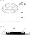
- tube 110 inner peripheral surface portion 120: outer peripheral surface portion 130: sample accommodating space 131: first sample accommodating space 132: second sample accommodating space 133: third sample accommodating space 140: partition wall 200: heating layer 300: electrode layer, 310: first electrode layer 320: second electrode layer
- a unit of % used in the present specification without particular description refers to weight %.
- a term such as "layer” or “film” described in the present specification refers to that each material forms a continuum and has a dimension in which thickness is relatively small as compared to width and length. Therefore, it is not to be interpreted that the term such as “layer” or “film” refers to a two-dimensional flat plane.
- a sample concentrator tube having a heat-resistant planar heating element adhered thereto includes a tube 100 having an internal structure in which a sorbent adsorbing a volatile material is filled; a heating layer 200 including a heat-resistant planar heating element adhered to an outer peripheral surface of the tube 100; and an electrode layer 300 formed on an outer peripheral surface of the heating layer 200.
- the volatile material which is a target to be analyzed in a general sample analysis device, refers to a material including an inorganic compound, an organic compound, or the like, that may exist in a gas phase.
- the volatile material include organic compounds including hydrocarbon compounds that may be volatilized in the air, and as specific examples, there are infinitely many kinds of organic compounds such as benzene, formaldehyde, xylene, ethylene, styrene, acetaldehyde, and the like.
- the inorganic compounds there are various materials such as hydrochloric acid, hydrofluoric acid, ammonia, hydrogen sulfide, and the like. That is, the volatile material described in the present specification may collectively indicate all detectable materials which have volatility and may exist in a gas phase.
- a geometric structure of the tube 100 is not limited as long as the tube 100 has a sample accommodating space 130 therein and has an open portion which a sample may be introduced into the sample accommodating space 130. That is, the tube 100 may literally refer to a tubular structure, and in this case, both ends of the tube may be opened.
- a shape of one end of the tube 100 that is, a shape of a cross-sectional surface of the tube in a direction vertical to a length direction of the tube 100 is not limited, but may be generally circular shape.
- the shape may be various shapes such as an oval shape, an n-gonal shape (n is 2 or more), a star shape, a shape in which a plurality of arcs having different degrees of curvature are connected to each other, and a shape in which one or more lines and one or more arcs are connected to each other, in addition to the circular shape.
- an inner diameter of the tube 100 is 1 to 5 mm, which is preferable in that thermal energy may be efficiently and effectively transferred to the sample, but the present invention is not necessarily limited thereto.
- a length and a thickness of the tube 100 may be suitably adjusted depending on a scale or specific use (for example, portable use, experimental use, large-scale facility measurement, or the like), the length and the thickness are not particularly limited.
- the tube 100 may have an outer diameter of 2 to 7 mm.
- a material of the tube 100 may be largely divided into a transparent material and an opaque material from an optical point of view.
- a transparent material may be selected in view of easy identification of a sample or a sorbent, and specific examples thereof may include glass having heat resistance to withstand a temperature of 250° C and preferably 350° C or higher, a heat-resistant transparent polymer material, and the like.
- Specific examples of the opaque material may include a ceramic material, a metal material, a metal oxide material, and a thermosetting polymer material, and the like.
- the tube has an insulation property so that a current applied to an electrode is not transferred to the tube 100 through the heating layer 200.
- an outer peripheral surface of a metal tube 100 on which the heating layer 200 is formed includes an electrical insulating layer, that is, an insulating layer formed to cover a metal layer.
- a member having a structure preventing the current applied to the heating layer 200 from flowing to the tube 100 or member playing the above-mentioned role may be added, and in a case where the problem described above does not occur, the material of the tube 100 itself is not limited.
- insulation refers to a property that electricity is not substantially conducted, that is, typically electrical resistance is high.
- the outer peripheral surface of the tube 100 on which the heating layer 200 is formed has an insulation property, and in view of further improving energy efficiency, precision in controlling a temperature, reproducibility, and the like, it is preferable that the tube 100 has a structure including a metal having high thermal conductivity and an electrical insulating layer including a porous anodic oxide film (PAOF) in which the metal is anodized.
- the tube 100 may have a tubular structure including an inner peripheral surface portion 110 and an outer peripheral surface portion 120, wherein the inner peripheral surface portion 110 may be an aluminum metal, and the outer peripheral surface portion 120 may be an aluminum-based porous anodic oxide film formed by anodization of the aluminum metal.
- thicknesses of the inner peripheral surface portion 110 and the outer peripheral surface portion 120 are not limited, but it is preferable that the thickness of the inner peripheral surface portion 110 is 200 to 1000 ⁇ m, and the outer peripheral surface portion 120 is 0.1 to 20 ⁇ m, specifically 0.3 to 10 ⁇ m, and more specifically 0.5 to 5 ⁇ m. In this case, it is possible to minimize a flow of the current to the inner peripheral surface portion 110 while improving precision in controlling the temperature, such that energy efficiency may be excellent, and precision in controlling the temperature may be further improved.
- the aluminum-based porous anodic oxide film formed by anodization may be formed by an anodization technology, which is one of surface treatment technologies of a metal, and a tube 100 including a metal surface in which various and regular nano-structures are formed using this technology may be used.
- an inner portion of the tube 100 may include first to n-th sample accommodating spaces formed by one or two or more partitions 140 walls provided therein.
- n is a natural number of 2 or more, and as a specific example, n may be selected from 2 to 20, but is not limited thereto.
- a material of the partition wall 140 a material equal to or different from that of the tube described above may be used, and a material having excellent thermal conductivity such as a metal, or the like, may be preferably used.
- the first to n-th sample accommodating spaces (here, n is a natural number of 2 or more) formed by one or two or more partition walls 140 provided therein are included in the tube 100 as described above
- thermal energy from the heating layer 200 may be rapidly and effectively transferred to the sorbent filled in each of the sample accommodating spaces through the metal structure having high thermal conductivity. Therefore, the volatile material adsorbed in the sorbent may be simultaneously desorbed, such that a trace amount of volatile material may be analyzed.
- thermal energy converted in the heating layer 200 may be efficiently transferred to the sorbent in each of the sample accommodating space through the tube having high thermal conductivity without thermal resistance due to the tube 100 adhered thereto, such that thermal desorption of the sample may be performed with high energy efficiency, stability of the sorbent may be increased, and reproducibility may be improved.
- a shape and a structure of the partition wall 140 are not particularly limited as long as the partition wall 140 may be connected to the inner peripheral surface of the tube to partition each of the sample accommodating spaces so that the sorbent is provided in each of the sample accommodating spaces.
- the partition wall 140 may be formed so that the cross-sectional surface has various shapes such as a circular shape, an oval shape, an n-gonal shape (n is 2 or more), a star shape, a shape in which a plurality of arcs having different degrees of curvature are connected to each other, and a shape in which one or more lines and one or more arcs are connected to each other.
- the sample concentrator tube includes the sorbent provided in the inner peripheral surface of the tube 100 so that the volatile material is adsorbed or concentrated therein.
- the sample is vaporized in a gas form through thermal desorption by heating to thereby be detected and analyzed. Therefore, it is required to precisely control a temperature of the sample, and in this case, the temperature may be precisely controlled and thermal damage of the sorbent may be prevented by using the sample concentrator tube having a heat-resistant planar heating element adhered thereto according to the present invention.
- a specific kind of sorbent is not particularly limited as the kind of sorbent is well-known in the field of analysis technology through sample concentration.
- a sorbent material having a specific surface area of 10 to 2000 m 2 /g and a density of 0.2 to 0.8 g/cm 3 may be used, and examples thereof may include a thermosetting polymer material such as an aromatic polymer or the like and carbon material such as active carbon, graphite, or the like.
- the inner peripheral surface of the tube 100 may be subjected to hydrophobic or hydrophilic surface-treatment so that the sample or the sorbent is not adsorbed.
- hydrophobic surface-treatment may include coating treatment using a fluorine-based compound, and the like
- hydrophilic surface-treatment may include plasma treatment using steam, nitrogen, or the like, acid treatment, and the like.
- these treatments are provided only as an example and specific examples of various treatment methods are referred in known documents, the present invention is not limited thereto.
- the concentrator tube is required to be easily detached from an analysis device and be easily attached thereto, a structure that is not complicated is required so that problems that may occur in this time are significantly decreased, and in particular, strong adhesion of each layer capable of withstanding large physical impact is required. Therefore, the concentrator tube having a heat-resistant planar heating element adhered thereto according to the present invention includes a planar heating layer 200 including a carbon nanotube or a carbon nanotube-metal complex, high stability may be expected in spite of various variables.
- the sorbent may be filled and accommodated in the tube 100, and may be filled that the inner portion of the tube 100 is sealed or not sealed.
- the concentrator tube having a heat-resistant planar heating element adhered thereto may further include an openable and closable sealing member.
- the concentrator tube having a heat-resistant planar heating element adhered thereto according to the present invention may further include a heat-resistant gas-permeable sealing member formed in the open portion, specifically, both end portions of the tube 100 and having a plurality of pores formed therein.
- the sealing member may be bonded to both opened ends of the tube 100 to seal the inner portion of the tube 100, and may be accommodated both end portions of the tube, for example, inwardly from both ends to seal the inner portion of the tube 100.
- a size of the pore is not limited as long as air may pass through the pore and the sorbent, or the like may be fixed.
- a material of the sealing member is not limited as long as the sealing member may be used at a temperature equal to or higher than a desorption temperature. For example, a glass fiber, or the like, may be used.
- the heating layer 200 includes a planar heating element including one or more selected from a carbon nanotube and a carbon-nanotube-metal complex, and as an example, the heating layer may be formed of a nanotube-based heat-resistant planar heating element.
- the planar heating element means that the planar heating member may stably generate heat to a temperature of about 350°C when a current is applied thereto, and the planar heating element may be formed on the heating layer to have a layered structure.
- a formation method thereof is not limited.
- the planar heating element may be a film (thin layer) formed by applying and drying (thermally-treating) a liquid composition of the planar heating element.
- application conditions temperature, humidity, time, and the like
- drying (thermal treatment) conditions temperature, humidity, time, and the like
- these conditions are not limited.
- the heating layer 200 may include a planar heating element formed of AccuPaste TM CNT Heating Paste (TC-1010, Bioneer), or the like. However, this is described only as a preferable example, other various planar heating elements may be used.
- the planar heating element is formed of a heating composition to be described below.
- the heating composition includes a carbon nanotube or a carbon nanotube-metal complex; and a silicone adhesive.
- the heating composition may include 20 to 80 wt% of the carbon nanotube or the carbon nanotube-metal complex and 20 to 80 wt% of the silicone adhesive.
- the silicone adhesive may contain 0.1 to 10 wt% of a silanol group based on 100 wt% of the adhesive, and a molar ratio of a phenyl group to a methyl group may be 0.3 to 2.5.
- a metal contained in the carbon nanotube-metal complex is not particularly limited, and examples thereof may include any one or two more selected from silver, platinum, gold, copper, nickel, iron, cobalt, aluminum, and the like.
- a content of the metal contained in the carbon nanotube-metal complex may be 1 to 80 parts by weight based on 100 parts by weight of the carbon nanotube-metal complex.
- the heating composition may further include any one or two or more selected from an organic binder, a dispersant, an organic solvent, and the like.
- the organic binder may be any one or more selected from ethylcellulose, nitrocellulose, and mixtures thereof
- the dispersant may include any one or two or more selected from the group consisting of phosphorus ester salts of an amino-containing oligomer or polymer, monoesters or diesters of phosphoric acid, acidic dicarboxylic acid monoesters, polyurethane-polyamine adducts, and polyalkoxylated monoamines or diamines
- the organic solvent may include any one or two or more selected from acetone, methyl ethyl ketone, methyl alcohol, ethyl alcohol, isopropyl alcohol, butyl alcohol, ethylene glycol, polyethylene glycol, tetrahydrofuran, dimethylformamide, dimethylacetamide, N-methyl-2-pyrrolidone, hexane, cyclohexanone, toluene, chloroform, dichlorobenzene, dimethylbenzene, trimethyl
- the heating composition further includes the organic binder, the dispersant, the organic solvent, or the like
- a composition ratio thereof is not particularly limited.
- the heating composition may include 1 to 50 wt% of the carbon nanotube or the carbon nanotube-metal complex, 1 to 20 wt% of the organic binder, 1 to 30 wt% of the silicone adhesive, 1 to 20 wt% of the dispersant, and 1 to 90 wt% of the organic solvent.
- the heating layer 200 including the planar heating element may be formed by coating the heating composition as described above on the tube 100, or the heating layer 200 including the planar heating element may be formed by a method such as adhesion of a heating sheet made of the heating composition.
- this case is described as a preferable example, and the present invention is not limited thereto.
- the heating wire and a tube 100 are not closely adhered to each other by linear expansion of the heating wire but are partially spaced apart from each other, and heat resistance in a spaced portion therebetween is thus increased, such that there are problems in that it takes a long time to heat the tube and a heating rate becomes non-uniform.
- the heating layer 200 is uniformly adhered to the tube 100, such that thermal energy may be rapidly and uniformly transferred as shown in FIG. 5 .
- the heating layer 200 includes the heat-resistant planar heating element which is formed of a composition including the carbon nanotube or the carbon nanotube-metal complex and the silicone based adhesive.
- the metal may include any one or two or more selected from silver, platinum, gold, copper, nickel, iron, cobalt, aluminum, and the like.
- the heating layer 200 may have sheet resistance of 2 to 15 ⁇ /sq, but this is only an example and the present invention is not limited thereto.
- the heating layer 200 is formed to enclose the outer peripheral surface of the tube 100
- the electrode layer 300 is formed to enclose an outer peripheral surface of the heating layer 200
- the heating layer 200 and the electrode layer 300 may have tubular structures in which the outer peripheral surfaces of respective targets may be completely enclosed and may not be completely enclosed.
- the heating layer 200 may be formed in a tubular shape to enclose the outer peripheral surface of the tube 100
- the electrode layer 300 may also be formed in a tubular shape to enclose an outer peripheral surface of the heating layer 200.
- a thickness of the heating layer 200 is in inversely proportional to electric resistance, and is not limited as long as the heating layer 200 receives electric energy from the electrode layer 300, converts the electric energy into thermal energy, and transfers thermal energy to the tube 100.
- the thickness of the heating layer 200 may be 20 to 100 ⁇ m. However, this is described as a specific example, and the present invention is not limited thereto.
- a material of the electrode layer 300 and a structure or a shape in which the electrode layer 300 is formed on the heating layer 200 are not particularly limited as long as the electrode layer 300 may apply a voltage to the heating layer 200, but the electrode layer 300 includes a first electrode layer 310 (300) and a second electrode layer 320 (300).
- the first electrode layer 310 (300) and the second electrode layer 320 (300) are formed to be spaced apart from each other on both end portions of the heating layer 200. Formation positions of the first electrode layer 310 (300) and the second electrode layer 320 (300) are not particularly limited as long as a voltage may be applied to each electrode layer 300 to heat the heating layer 200.
- a spaced distance between the first electrode layer 310 (300) and the second electrode layer 320 (300) may be adjusted in consideration of various variables such as lengths of the tube 100 and the heating layer 200, an area of each electrode layer 300, and the like, the spaced distance is not particularly limited.
- any electrode layer 300 formed of an electrode generally used may be used.
- the electrode layer 300 may be formed of a conductive material such as copper, iron, or the like, but the present invention is not limited thereto.
- a precious metal layer covering the metal layer may be further formed in view of improving energy efficiency. Examples of a metal used in the precious metal layer may include gold, platinum, and the like, but in addition to these metals, any precious metal may be used without limitation as long as the metal may improve energy efficiency.
- a thickness of the electrode layer 300 is not limited as long as the electrode layer 300 may be stably bonded to the tube and may apply electricity to the heating layer.
- the thickness may be 50 ⁇ m to 5 mm, specifically, 100 ⁇ m to 1,000 ⁇ m, but is not limited thereto.
- the electrode layer 300 may be formed to come in contact with the heating layer 200 by various methods.
- the electrode layer 300 may be formed using a plating method, a brush plating method, a vapor deposition method, and the like, or formed by fixing a metal ring with conductive epoxy, or the like, but may also be formed by various methods in addition to the above-mentioned methods. Therefore, the present invention is not limited thereto.
- the sample concentrator tube having a heat-resistant planar heating element adhered thereto may further include an insulating layer for protecting the heating layer on the outer peripheral surface of the heating layer 200.
- the sample concentrator tube having a heat-resistant planar heating element adhered thereto may further include a temperature measurement portion provided on the outer peripheral surface or the inner peripheral surface of the tube 100.
- a sensor capable of sensing a temperature may be used.
- a contact temperature sensor including any one or two or more selected from a thermocouple temperature sensor, a resistive temperature detector (RTD), a thermistor temperature sensor, and the like, or any one or more selected among non-contact temperature sensor including infrared temperature sensors, and the like may be used.
- a volatile material analysis device may include the above-mentioned sample concentrator tube having a heat-resistant planar heating element adhered thereto.
- the volatile material analysis device may include the sample concentrator tube having a heat-resistant planar heating element adhered thereto, including a temperature measurement portion provided on the outer peripheral surface or the inner peripheral surface of the tube 100; a detection portion into which a sample is introduced from the sample concentrator tube; and a control portion receiving a measured value for a temperature in the tube from the temperature measurement portion and comparing the measured value with a preset value to control a voltage applied to the electrode layer 300.
- the detection portion may refer to a device capable of detecting and analyzing a sample and is widely known in a gas sample analysis technology field, the detection portion is not limited.
- the detection portion may include a detection/analysis device such as a gas chromatography (GC), a mass spectrometer (MS), an ion mobility spectrometer, or the like.
- a detection/analysis device such as a gas chromatography (GC), a mass spectrometer (MS), an ion mobility spectrometer, or the like.
- the control portion may monitor a temperature through the temperature measurement portion, and control a temperature of the tube 100 to a target temperature by feedback through a current or voltage control device, or the like. Specifically, when the measured value from the temperature measurement portion is smaller than the preset value, the control portion may serve to increase a voltage applied to the electrode layer 300, and when the measured value from the temperature measurement portion is larger than the preset value, the control portion may serve to decrease a voltage applied to the electrode layer 300.
- a volatile material analysis method may include: accommodating a sorbent suitable for a sample to be concentrated in a tube 100 (S1); sealing an opening portion of the tube 100 with a heat-resistant gas-permeable sealing member in which pores are formed (S2); allowing a gas including the sample to pass through the inside of the tube 100 to adsorb and concentrate the sample in the sorbent (S3); applying a voltage to an electrode layer 300 to thermally desorb the concentrated sample from the sorbent (S4); and introducing the thermally desorbed concentrated sample into a detection portion to analyze the concentrated sample (S5).
- a temperature at the time of concentrating the sample is not limited as long as the sample may be concentrated to thereby be adsorbed in the sorbent in a liquid or solid phase, and generally, the temperature may be room temperature, for example, 0 to 25°C. However, the temperature is not particularly limited as long as the sample may be adsorbed.
- a temperature for thermal desorption of the sample is not limited as long as the sample may be desorbed from the sorbent to thereby be introduced into the outside.
- the temperature may be 100 to 350°C, but since the temperature may be changed depending on the kind of sample, the temperature is not limited thereto.
Landscapes
- Chemical & Material Sciences (AREA)
- Analytical Chemistry (AREA)
- Health & Medical Sciences (AREA)
- Life Sciences & Earth Sciences (AREA)
- Engineering & Computer Science (AREA)
- Immunology (AREA)
- General Health & Medical Sciences (AREA)
- General Physics & Mathematics (AREA)
- Physics & Mathematics (AREA)
- Pathology (AREA)
- Biochemistry (AREA)
- Oil, Petroleum & Natural Gas (AREA)
- General Chemical & Material Sciences (AREA)
- Chemical Kinetics & Catalysis (AREA)
- Combustion & Propulsion (AREA)
- Food Science & Technology (AREA)
- Medicinal Chemistry (AREA)
- Sampling And Sample Adjustment (AREA)
- Separation Of Gases By Adsorption (AREA)
Claims (13)
- Probenkonzentratorrohr, umfassend:ein Rohr (100) mit einer inneren Struktur, worin ein Sorptionsmittel gefüllt ist, das einen flüchtigen Stoff adsorbiert;eine Heizschicht (200), die ein hitzebeständiges flächiges Heizelement enthält, das an einer äußeren Umfangsfläche des Rohrs haftet; undeine Elektrodenschicht (300), die auf einer äußeren Umfangsfläche der Heizschicht (200) ausgebildet ist,wobei die Heizschicht (200) elektrische Energie von der Elektrodenschicht (300) empfängt, die elektrische Energie in thermische Energie umwandelt und die thermische Energie auf das Rohr (100) überträgt,wobei die Elektrodenschicht (300) eine erste (310) und eine zweite (320) Elektrodenschicht umfasst, und die erste und die zweite Elektrodenschicht (310, 320) so ausgebildet sind, dass sie an beiden Endabschnitten der Heizschicht (200) voneinander beabstandet sind, undwobei das flächige Heizelement aus einer Heizzusammensetzung gebildet ist, die ein Kohlenstoffnanoröhrchen oder einen Kohlenstoffnanoröhrchen-Metall-Komplex und einen Silikonklebstoff enthält.
- Probenkonzentratorrohr nach Anspruch 1, wobei das Rohr (100) aus einem elektrisch isolierenden Material hergestellt ist oder die äußere Umfangsfläche des Rohrs (100), auf der die Heizschicht (200) ausgebildet ist, eine elektrisch isolierende Schicht enthält.
- Probenkonzentratorrohr nach Anspruch 2, wobei das Rohr (100) eine röhrenförmige Struktur mit einem inneren Umfangsoberflächenteil (110) und einem äußeren Umfangsoberflächenteil (120) aufweist, und
der innere Umfangsoberflächenteil (110) aus einem Metallmaterial hergestellt ist und der äußere Umfangsoberflächenteil (120) eine elektrisch isolierende Schicht ist, die aus einem Metalloxid gebildet ist, das durch Anodisierung des inneren Umfangsoberflächenteils (110) erhalten wird. - Probenkonzentratorrohr nach Anspruch 1, wobei das Rohr (100) ferner ein hitzebeständiges, gasdurchlässiges Dichtungselement enthält, in dem eine Vielzahl von Poren zur Fixierung des Sorptionsmittels ausgebildet ist.
- Probenkonzentratorrohr nach Anspruch 1, wobei die Heizschicht (200) rohrförmig ausgebildet ist, um die äußere Umfangsfläche (120) des Rohrs (100) zu umschließen, und die Elektrodenschicht rohrförmig ausgebildet ist, um die äußere Umfangsfläche (120) der Heizschicht (200) zu umschließen.
- Probenkonzentratorrohr nach Anspruch 1, wobei ein Metall des Kohlenstoffnanoröhrchen-Metall-Komplexes eines oder zwei oder mehr Metalle umfasst, die aus Silber, Platin, Gold, Kupfer, Nickel, Eisen, Kobalt und Aluminium ausgewählt sind.
- Probenkonzentratorrohr nach Anspruch 6, wobei die Heizschicht (200) einen Flächenwiderstand von 2 bis 15 Ω/sq. aufweist.
- Probenkonzentratorrohr nach Anspruch 1, wobei die Heizschicht (200) eine durchschnittliche Dicke von 20 bis 100 µm aufweist.
- Probenkonzentratorrohr nach Anspruch 1, ferner umfassend einen Temperaturmessabschnitt, der an der äußeren Umfangsfläche (120) oder einer inneren Umfangsfläche (110) des Rohrs vorgesehen ist.
- Probenkonzentratorrohr nach Anspruch 1, wobei das Sorptionsmittel, das die Adsorption oder Desorption des flüchtigen Stoffs ermöglicht, an der inneren Umfangsfläche (110) des Rohrs (100) vorgesehen ist.
- Vorrichtung zur Analyse flüchtiger Stoffe, die das Probenkonzentratorrohr nach einem der Ansprüche 1 bis 10 umfasst.
- Vorrichtung zur Analyse flüchtiger Stoffe nach Anspruch 11, umfassend:das Probenkonzentratorrohr, das einen Temperaturmessabschnitt aufweist, der an der äußeren Umfangsfläche (120) oder der inneren Umfangsfläche (110) des Rohrs vorgesehen ist;einen Nachweisabschnitt, in den eine Probe aus dem Probenkonzentratorrohr eingeführt wird; undeinen Steuerabschnitt, der einen gemessenen Wert für eine Temperatur in der Röhre (100) von dem Temperaturmessabschnitt empfängt und den gemessenen Wert mit einem voreingestellten Wert vergleicht, um eine an die Elektrodenschicht (300) angelegte Spannung zu steuern.
- Verfahren zur Analyse flüchtiger Stoffe unter Verwendung des Probenkonzentratorrohrs nach einem der Ansprüche 1 bis 12, umfassend:Unterbringen eines für eine zu konzentrierende Probe geeigneten Sorptionsmittels in dem Rohr (S1);Abdichten eines Öffnungsabschnitts des Rohrs mit einem hitzebeständigen, gasdurchlässigen Dichtungselement, in dem Poren ausgebildet sind (S2);ein Gas, das die Probe enthält, durch das Innere des Rohr strömen zu lassen, um die Probe in dem Sorptionsmittel zu adsorbieren und zu konzentrieren (S3);Anlegen einer Spannung an die Elektrodenschicht zur thermischen Desorption der konzentrierten Probe aus dem Sorptionsmittel (S4); undEinbringen der thermisch desorbierten konzentrierten Probe in ein Nachweisteil, um die konzentrierte Probe zu analysieren.
Applications Claiming Priority (2)
| Application Number | Priority Date | Filing Date | Title |
|---|---|---|---|
| KR1020190002906A KR102156728B1 (ko) | 2019-01-09 | 2019-01-09 | 내열성 면상발열체가 접착된 시료농축튜브와 이를 포함하는 분석 장치 및 이를 이용한 분석 방법 |
| PCT/KR2019/018823 WO2020145563A1 (ko) | 2019-01-09 | 2019-12-31 | 내열성 면상발열체가 접착된 시료농축튜브와 이를 포함하는 분석 장치 및 이를 이용한 분석 방법 |
Publications (4)
| Publication Number | Publication Date |
|---|---|
| EP3910313A1 EP3910313A1 (de) | 2021-11-17 |
| EP3910313A4 EP3910313A4 (de) | 2022-10-26 |
| EP3910313C0 EP3910313C0 (de) | 2025-04-30 |
| EP3910313B1 true EP3910313B1 (de) | 2025-04-30 |
Family
ID=71520990
Family Applications (1)
| Application Number | Title | Priority Date | Filing Date |
|---|---|---|---|
| EP19909471.5A Active EP3910313B1 (de) | 2019-01-09 | 2019-12-31 | Probenkonzentratorrohr mit daran anhaftendem hitzebeständigem ebenem heizelement, analysevorrichtung damit und analyseverfahren mit verwendung davon |
Country Status (7)
| Country | Link |
|---|---|
| US (1) | US20220065759A1 (de) |
| EP (1) | EP3910313B1 (de) |
| JP (1) | JP2022516345A (de) |
| KR (1) | KR102156728B1 (de) |
| CN (1) | CN113286996A (de) |
| ES (1) | ES3025799T3 (de) |
| WO (1) | WO2020145563A1 (de) |
Families Citing this family (2)
| Publication number | Priority date | Publication date | Assignee | Title |
|---|---|---|---|---|
| CN114939324A (zh) * | 2022-05-26 | 2022-08-26 | 广西电网有限责任公司电力科学研究院 | 一种悬挂式电力开关柜气体吸附装置 |
| KR102579429B1 (ko) * | 2023-01-17 | 2023-09-15 | 주식회사 팀즈 | 전도성물질 기반의 히터를 이용한 열전달효율이 우수한 인라인 히팅시스템 |
Family Cites Families (26)
| Publication number | Priority date | Publication date | Assignee | Title |
|---|---|---|---|---|
| JP2000077167A (ja) * | 1998-08-31 | 2000-03-14 | Kyocera Corp | 面状発熱体 |
| AU3262701A (en) * | 1999-11-17 | 2001-05-30 | Femtometrics, Inc. | Preconcentrator for chemical detection |
| JP2002131201A (ja) * | 2000-10-27 | 2002-05-09 | Shimadzu Corp | ニオイ測定装置 |
| KR20050059364A (ko) * | 2003-12-13 | 2005-06-20 | 한국전자통신연구원 | 가스 흡착 및 탈착 장치 및 그 제작 방법 |
| JP4228963B2 (ja) * | 2004-03-30 | 2009-02-25 | 株式会社島津製作所 | ガス分析装置 |
| KR100631487B1 (ko) * | 2004-11-11 | 2006-10-09 | 건국대학교 산학협력단 | 악취물질 및 휘발성 유기화합물질의 농축을 위한흡착트랩이 구비된 시료포집장치 |
| KR100583586B1 (ko) * | 2004-11-16 | 2006-05-26 | 건국대학교 산학협력단 | 악취물질 및 휘발성 유기화합물질의 농축을 위한 다단흡착장치 |
| US7449050B2 (en) * | 2005-12-29 | 2008-11-11 | Microsensor Systems, Inc. | System, apparatus and method for concentrating chemical vapors |
| US7430928B2 (en) * | 2006-02-08 | 2008-10-07 | Battelle Memorial Insititute | Method and apparatus for concentrating vapors for analysis |
| JP2009024902A (ja) * | 2007-07-17 | 2009-02-05 | Mitsubishi Plastics Inc | 流体加熱装置、及び流体加熱装置の製造方法 |
| CN101409961B (zh) * | 2007-10-10 | 2010-06-16 | 清华大学 | 面热光源,其制备方法及应用其加热物体的方法 |
| CN101868072B (zh) * | 2009-04-20 | 2015-06-03 | 清华大学 | 线热源的制备方法 |
| US20100122980A1 (en) * | 2008-06-13 | 2010-05-20 | Tsinghua University | Carbon nanotube heater |
| KR101456284B1 (ko) * | 2009-10-28 | 2014-11-04 | (주)바이오니아 | 시료 농축장치 |
| KR101158851B1 (ko) * | 2009-12-18 | 2012-06-22 | 서울대학교산학협력단 | 흡착 및 탈착 장치 |
| KR101245461B1 (ko) * | 2009-12-30 | 2013-03-19 | (주)엘지하우시스 | 진공단열재를 적용한 면상 발열체 및 이를 제조하는 방법 |
| KR101313149B1 (ko) | 2010-04-16 | 2013-09-30 | (주)바이오니아 | 탄소나노튜브―금속 복합체의 제조방법 및 이를 이용한 전도성 페이스트의 제조방법 |
| KR101527102B1 (ko) * | 2010-11-26 | 2015-06-10 | (주)바이오니아 | 유해물질 제거 장치 |
| WO2012073820A1 (ja) * | 2010-11-30 | 2012-06-07 | シャープ株式会社 | 電極構造、基材保持装置および陽極酸化層の形成方法 |
| TW201311336A (zh) * | 2011-09-09 | 2013-03-16 | Ind Tech Res Inst | 吸附元件、吸附裝置及其再生方法 |
| KR101447478B1 (ko) | 2013-07-12 | 2014-10-06 | (주)바이오니아 | 탄소나노튜브 또는 탄소나노튜브-금속 복합체를 이용한 세라믹 페이스트 조성물 및 이를 포함하는 도전성 필름 |
| KR101595484B1 (ko) * | 2014-05-02 | 2016-02-19 | 주식회사 덴다인더스트리 | 면상발열체 및 그의 제조방법 |
| WO2015178337A1 (ja) * | 2014-05-19 | 2015-11-26 | 株式会社アイ.エス.テイ | 面状抵抗発熱体および抵抗発熱シームレス管状物ならびに導電性粒子含有樹脂溶液 |
| JP2017142162A (ja) * | 2016-02-10 | 2017-08-17 | Msi.Tokyo株式会社 | 加熱式試料吸着管及びそれを含む質量分析装置 |
| KR20170104753A (ko) * | 2016-03-08 | 2017-09-18 | 주식회사 슈파인 | 탄소나노튜브(cnt) 스펀지를 사용한 휘발성 유기화합물 농축 장치 |
| KR101814964B1 (ko) | 2017-11-23 | 2018-01-31 | 고신대학교 산학협력단 | 탈착 가속 장치를 구비한 휘발성 유기화합물 처리 시스템의 VOCs 농축 모듈 |
-
2019
- 2019-01-09 KR KR1020190002906A patent/KR102156728B1/ko active Active
- 2019-12-31 US US17/309,965 patent/US20220065759A1/en not_active Abandoned
- 2019-12-31 JP JP2021539348A patent/JP2022516345A/ja active Pending
- 2019-12-31 EP EP19909471.5A patent/EP3910313B1/de active Active
- 2019-12-31 CN CN201980088301.5A patent/CN113286996A/zh active Pending
- 2019-12-31 WO PCT/KR2019/018823 patent/WO2020145563A1/ko not_active Ceased
- 2019-12-31 ES ES19909471T patent/ES3025799T3/es active Active
Also Published As
| Publication number | Publication date |
|---|---|
| EP3910313C0 (de) | 2025-04-30 |
| ES3025799T3 (en) | 2025-06-09 |
| US20220065759A1 (en) | 2022-03-03 |
| KR102156728B1 (ko) | 2020-09-16 |
| EP3910313A1 (de) | 2021-11-17 |
| EP3910313A4 (de) | 2022-10-26 |
| KR20200086555A (ko) | 2020-07-17 |
| CN113286996A (zh) | 2021-08-20 |
| JP2022516345A (ja) | 2022-02-25 |
| WO2020145563A1 (ko) | 2020-07-16 |
Similar Documents
| Publication | Publication Date | Title |
|---|---|---|
| CN103380362B (zh) | 向化学分析器中引入分析物 | |
| US8117896B2 (en) | Preconcentrators and methods of making and using the same | |
| US8191435B2 (en) | Method and apparatus for concentrating vapors for analysis | |
| ES2549160T3 (es) | Línea de transferencia para sonda de muestreo | |
| EP3351920B1 (de) | Konzentrator einer chemischen substanz und vorrichtung zum nachweis einer chemischen substanz | |
| EP3910313B1 (de) | Probenkonzentratorrohr mit daran anhaftendem hitzebeständigem ebenem heizelement, analysevorrichtung damit und analyseverfahren mit verwendung davon | |
| Camara et al. | Tubular gas preconcentrators based on inkjet printed micro-hotplates on foil | |
| EP0855596A2 (de) | Gaschromatographiesystem | |
| WO2016103561A1 (ja) | 化学物質濃縮器および化学物質検出装置 | |
| US20170189882A1 (en) | Preconcentrator for absorbing/desorbing at least one component of gas | |
| Young et al. | Ethanol gas sensors composed of carbon nanotubes with Au nanoparticles adsorbed onto a flexible PI substrate | |
| Lee et al. | In situ calibration of micro-photoionization detectors in a multi-dimensional micro-gas chromatography system | |
| Winter et al. | Temporally resolved thermal desorption of volatile organics from nanoporous silica preconcentrator | |
| KR20040111397A (ko) | 집적된 가스 센서 | |
| Lee et al. | Direct integration of carbon nanotubes on a suspended Pt microheater for hydrogen gas sensing | |
| Karimov et al. | Resistive humidity sensor based on vanadium complex films | |
| US7994453B2 (en) | Flash heating for tubing | |
| ur Rehman et al. | Investigating sensing properties of poly-(dioctylfluorene) based planar sensor | |
| WO2013175503A2 (en) | Nanostructure based mems preconcentrator | |
| US20170023508A1 (en) | Method of making thin film humidity sensors | |
| Sattarzadeh et al. | Fabrication of a humidity sensor based on chemical vapor deposition-synthesized single-walled carbon nanotubes | |
| KR101186523B1 (ko) | 휴대용 가스분석 시스템을 위한 마이크로 전농축기 | |
| Ivanov et al. | SOI-CMOS compatible low-power gas sensor using sputtered and drop-coated metal-oxide active layers | |
| Pyshkin et al. | Evidence for sensory effects of a 1D organic conductor under gas exposure | |
| KR102489142B1 (ko) | 정전용량형 가스센서 및 그 제조 방법 |
Legal Events
| Date | Code | Title | Description |
|---|---|---|---|
| STAA | Information on the status of an ep patent application or granted ep patent |
Free format text: STATUS: THE INTERNATIONAL PUBLICATION HAS BEEN MADE |
|
| PUAI | Public reference made under article 153(3) epc to a published international application that has entered the european phase |
Free format text: ORIGINAL CODE: 0009012 |
|
| STAA | Information on the status of an ep patent application or granted ep patent |
Free format text: STATUS: REQUEST FOR EXAMINATION WAS MADE |
|
| 17P | Request for examination filed |
Effective date: 20210707 |
|
| AK | Designated contracting states |
Kind code of ref document: A1 Designated state(s): AL AT BE BG CH CY CZ DE DK EE ES FI FR GB GR HR HU IE IS IT LI LT LU LV MC MK MT NL NO PL PT RO RS SE SI SK SM TR |
|
| DAV | Request for validation of the european patent (deleted) | ||
| DAX | Request for extension of the european patent (deleted) | ||
| A4 | Supplementary search report drawn up and despatched |
Effective date: 20220926 |
|
| RIC1 | Information provided on ipc code assigned before grant |
Ipc: H05B 3/40 20060101ALI20220920BHEP Ipc: H05B 3/20 20060101ALI20220920BHEP Ipc: B01D 53/04 20060101ALI20220920BHEP Ipc: G01N 1/40 20060101AFI20220920BHEP |
|
| STAA | Information on the status of an ep patent application or granted ep patent |
Free format text: STATUS: EXAMINATION IS IN PROGRESS |
|
| 17Q | First examination report despatched |
Effective date: 20240202 |
|
| GRAP | Despatch of communication of intention to grant a patent |
Free format text: ORIGINAL CODE: EPIDOSNIGR1 |
|
| STAA | Information on the status of an ep patent application or granted ep patent |
Free format text: STATUS: GRANT OF PATENT IS INTENDED |
|
| INTG | Intention to grant announced |
Effective date: 20250122 |
|
| GRAS | Grant fee paid |
Free format text: ORIGINAL CODE: EPIDOSNIGR3 |
|
| GRAA | (expected) grant |
Free format text: ORIGINAL CODE: 0009210 |
|
| STAA | Information on the status of an ep patent application or granted ep patent |
Free format text: STATUS: THE PATENT HAS BEEN GRANTED |
|
| AK | Designated contracting states |
Kind code of ref document: B1 Designated state(s): AL AT BE BG CH CY CZ DE DK EE ES FI FR GB GR HR HU IE IS IT LI LT LU LV MC MK MT NL NO PL PT RO RS SE SI SK SM TR |
|
| REG | Reference to a national code |
Ref country code: CH Ref legal event code: EP Ref country code: GB Ref legal event code: FG4D |
|
| REG | Reference to a national code |
Ref country code: DE Ref legal event code: R096 Ref document number: 602019069495 Country of ref document: DE |
|
| REG | Reference to a national code |
Ref country code: IE Ref legal event code: FG4D |
|
| U01 | Request for unitary effect filed |
Effective date: 20250430 |
|
| REG | Reference to a national code |
Ref country code: ES Ref legal event code: FG2A Ref document number: 3025799 Country of ref document: ES Kind code of ref document: T3 Effective date: 20250609 |
|
| U07 | Unitary effect registered |
Designated state(s): AT BE BG DE DK EE FI FR IT LT LU LV MT NL PT RO SE SI Effective date: 20250508 |
|
| PG25 | Lapsed in a contracting state [announced via postgrant information from national office to epo] |
Ref country code: GR Free format text: LAPSE BECAUSE OF FAILURE TO SUBMIT A TRANSLATION OF THE DESCRIPTION OR TO PAY THE FEE WITHIN THE PRESCRIBED TIME-LIMIT Effective date: 20250731 Ref country code: NO Free format text: LAPSE BECAUSE OF FAILURE TO SUBMIT A TRANSLATION OF THE DESCRIPTION OR TO PAY THE FEE WITHIN THE PRESCRIBED TIME-LIMIT Effective date: 20250730 |
|
| PG25 | Lapsed in a contracting state [announced via postgrant information from national office to epo] |
Ref country code: PL Free format text: LAPSE BECAUSE OF FAILURE TO SUBMIT A TRANSLATION OF THE DESCRIPTION OR TO PAY THE FEE WITHIN THE PRESCRIBED TIME-LIMIT Effective date: 20250430 |
|
| PG25 | Lapsed in a contracting state [announced via postgrant information from national office to epo] |
Ref country code: HR Free format text: LAPSE BECAUSE OF FAILURE TO SUBMIT A TRANSLATION OF THE DESCRIPTION OR TO PAY THE FEE WITHIN THE PRESCRIBED TIME-LIMIT Effective date: 20250430 |
|
| PG25 | Lapsed in a contracting state [announced via postgrant information from national office to epo] |
Ref country code: RS Free format text: LAPSE BECAUSE OF FAILURE TO SUBMIT A TRANSLATION OF THE DESCRIPTION OR TO PAY THE FEE WITHIN THE PRESCRIBED TIME-LIMIT Effective date: 20250731 |
|
| PG25 | Lapsed in a contracting state [announced via postgrant information from national office to epo] |
Ref country code: IS Free format text: LAPSE BECAUSE OF FAILURE TO SUBMIT A TRANSLATION OF THE DESCRIPTION OR TO PAY THE FEE WITHIN THE PRESCRIBED TIME-LIMIT Effective date: 20250830 |
|
| U20 | Renewal fee for the european patent with unitary effect paid |
Year of fee payment: 7 Effective date: 20251110 |
|
| REG | Reference to a national code |
Ref country code: CH Ref legal event code: U11 Free format text: ST27 STATUS EVENT CODE: U-0-0-U10-U11 (AS PROVIDED BY THE NATIONAL OFFICE) Effective date: 20260101 |
|
| PGFP | Annual fee paid to national office [announced via postgrant information from national office to epo] |
Ref country code: GB Payment date: 20251114 Year of fee payment: 7 |
|
| PG25 | Lapsed in a contracting state [announced via postgrant information from national office to epo] |
Ref country code: SM Free format text: LAPSE BECAUSE OF FAILURE TO SUBMIT A TRANSLATION OF THE DESCRIPTION OR TO PAY THE FEE WITHIN THE PRESCRIBED TIME-LIMIT Effective date: 20250430 |
|
| PG25 | Lapsed in a contracting state [announced via postgrant information from national office to epo] |
Ref country code: CZ Free format text: LAPSE BECAUSE OF FAILURE TO SUBMIT A TRANSLATION OF THE DESCRIPTION OR TO PAY THE FEE WITHIN THE PRESCRIBED TIME-LIMIT Effective date: 20250430 |
|
| PG25 | Lapsed in a contracting state [announced via postgrant information from national office to epo] |
Ref country code: SK Free format text: LAPSE BECAUSE OF FAILURE TO SUBMIT A TRANSLATION OF THE DESCRIPTION OR TO PAY THE FEE WITHIN THE PRESCRIBED TIME-LIMIT Effective date: 20250430 |
|
| PLBE | No opposition filed within time limit |
Free format text: ORIGINAL CODE: 0009261 |
|
| STAA | Information on the status of an ep patent application or granted ep patent |
Free format text: STATUS: NO OPPOSITION FILED WITHIN TIME LIMIT |
|
| REG | Reference to a national code |
Ref country code: CH Ref legal event code: L10 Free format text: ST27 STATUS EVENT CODE: U-0-0-L10-L00 (AS PROVIDED BY THE NATIONAL OFFICE) Effective date: 20260311 |
|
| 26N | No opposition filed |
Effective date: 20260202 |
|
| PGFP | Annual fee paid to national office [announced via postgrant information from national office to epo] |
Ref country code: ES Payment date: 20260114 Year of fee payment: 7 |