EP3902121A1 - Stator adhesive laminated core and rotating electric machine - Google Patents
Stator adhesive laminated core and rotating electric machine Download PDFInfo
- Publication number
- EP3902121A1 EP3902121A1 EP19899295.0A EP19899295A EP3902121A1 EP 3902121 A1 EP3902121 A1 EP 3902121A1 EP 19899295 A EP19899295 A EP 19899295A EP 3902121 A1 EP3902121 A1 EP 3902121A1
- Authority
- EP
- European Patent Office
- Prior art keywords
- electrical steel
- average thickness
- laminated core
- adhesion
- average
- Prior art date
- Legal status (The legal status is an assumption and is not a legal conclusion. Google has not performed a legal analysis and makes no representation as to the accuracy of the status listed.)
- Granted
Links
Images

Classifications
-
- H—ELECTRICITY
- H02—GENERATION; CONVERSION OR DISTRIBUTION OF ELECTRIC POWER
- H02K—DYNAMO-ELECTRIC MACHINES
- H02K1/00—Details of the magnetic circuit
- H02K1/06—Details of the magnetic circuit characterised by the shape, form or construction
- H02K1/12—Stationary parts of the magnetic circuit
- H02K1/18—Means for mounting or fastening magnetic stationary parts on to, or to, the stator structures
-
- H—ELECTRICITY
- H01—ELECTRIC ELEMENTS
- H01F—MAGNETS; INDUCTANCES; TRANSFORMERS; SELECTION OF MATERIALS FOR THEIR MAGNETIC PROPERTIES
- H01F27/00—Details of transformers or inductances, in general
- H01F27/24—Magnetic cores
- H01F27/245—Magnetic cores made from sheets, e.g. grain-oriented
-
- C—CHEMISTRY; METALLURGY
- C09—DYES; PAINTS; POLISHES; NATURAL RESINS; ADHESIVES; COMPOSITIONS NOT OTHERWISE PROVIDED FOR; APPLICATIONS OF MATERIALS NOT OTHERWISE PROVIDED FOR
- C09J—ADHESIVES; NON-MECHANICAL ASPECTS OF ADHESIVE PROCESSES IN GENERAL; ADHESIVE PROCESSES NOT PROVIDED FOR ELSEWHERE; USE OF MATERIALS AS ADHESIVES
- C09J133/00—Adhesives based on homopolymers or copolymers of compounds having one or more unsaturated aliphatic radicals, each having only one carbon-to-carbon double bond, and at least one being terminated by only one carboxyl radical, or of salts, anhydrides, esters, amides, imides, or nitriles thereof; Adhesives based on derivatives of such polymers
- C09J133/04—Homopolymers or copolymers of esters
-
- H—ELECTRICITY
- H01—ELECTRIC ELEMENTS
- H01F—MAGNETS; INDUCTANCES; TRANSFORMERS; SELECTION OF MATERIALS FOR THEIR MAGNETIC PROPERTIES
- H01F41/00—Apparatus or processes specially adapted for manufacturing or assembling magnets, inductances or transformers; Apparatus or processes specially adapted for manufacturing materials characterised by their magnetic properties
- H01F41/02—Apparatus or processes specially adapted for manufacturing or assembling magnets, inductances or transformers; Apparatus or processes specially adapted for manufacturing materials characterised by their magnetic properties for manufacturing cores, coils, or magnets
- H01F41/0206—Manufacturing of magnetic cores by mechanical means
- H01F41/0233—Manufacturing of magnetic circuits made from sheets
-
- H—ELECTRICITY
- H02—GENERATION; CONVERSION OR DISTRIBUTION OF ELECTRIC POWER
- H02K—DYNAMO-ELECTRIC MACHINES
- H02K1/00—Details of the magnetic circuit
- H02K1/04—Details of the magnetic circuit characterised by the material used for insulating the magnetic circuit or parts thereof
-
- H—ELECTRICITY
- H02—GENERATION; CONVERSION OR DISTRIBUTION OF ELECTRIC POWER
- H02K—DYNAMO-ELECTRIC MACHINES
- H02K1/00—Details of the magnetic circuit
- H02K1/06—Details of the magnetic circuit characterised by the shape, form or construction
- H02K1/12—Stationary parts of the magnetic circuit
- H02K1/18—Means for mounting or fastening magnetic stationary parts on to, or to, the stator structures
- H02K1/185—Means for mounting or fastening magnetic stationary parts on to, or to, the stator structures to outer stators
-
- H—ELECTRICITY
- H02—GENERATION; CONVERSION OR DISTRIBUTION OF ELECTRIC POWER
- H02K—DYNAMO-ELECTRIC MACHINES
- H02K15/00—Processes or apparatus specially adapted for manufacturing, assembling, maintaining or repairing of dynamo-electric machines
- H02K15/02—Processes or apparatus specially adapted for manufacturing, assembling, maintaining or repairing of dynamo-electric machines of stator or rotor bodies
- H02K15/021—Magnetic cores
-
- C—CHEMISTRY; METALLURGY
- C09—DYES; PAINTS; POLISHES; NATURAL RESINS; ADHESIVES; COMPOSITIONS NOT OTHERWISE PROVIDED FOR; APPLICATIONS OF MATERIALS NOT OTHERWISE PROVIDED FOR
- C09J—ADHESIVES; NON-MECHANICAL ASPECTS OF ADHESIVE PROCESSES IN GENERAL; ADHESIVE PROCESSES NOT PROVIDED FOR ELSEWHERE; USE OF MATERIALS AS ADHESIVES
- C09J2203/00—Applications of adhesives in processes or use of adhesives in the form of films or foils
- C09J2203/326—Applications of adhesives in processes or use of adhesives in the form of films or foils for bonding electronic components such as wafers, chips or semiconductors
-
- H—ELECTRICITY
- H02—GENERATION; CONVERSION OR DISTRIBUTION OF ELECTRIC POWER
- H02K—DYNAMO-ELECTRIC MACHINES
- H02K2213/00—Specific aspects, not otherwise provided for and not covered by codes H02K2201/00 - H02K2211/00
- H02K2213/03—Machines characterised by numerical values, ranges, mathematical expressions or similar information
-
- Y—GENERAL TAGGING OF NEW TECHNOLOGICAL DEVELOPMENTS; GENERAL TAGGING OF CROSS-SECTIONAL TECHNOLOGIES SPANNING OVER SEVERAL SECTIONS OF THE IPC; TECHNICAL SUBJECTS COVERED BY FORMER USPC CROSS-REFERENCE ART COLLECTIONS [XRACs] AND DIGESTS
- Y02—TECHNOLOGIES OR APPLICATIONS FOR MITIGATION OR ADAPTATION AGAINST CLIMATE CHANGE
- Y02T—CLIMATE CHANGE MITIGATION TECHNOLOGIES RELATED TO TRANSPORTATION
- Y02T10/00—Road transport of goods or passengers
- Y02T10/60—Other road transportation technologies with climate change mitigation effect
- Y02T10/64—Electric machine technologies in electromobility
Definitions
- the present invention relates to an adhesively-laminated core for a stator and an electric motor.
- Patent Document 1 discloses a direct drive motor including a stator disposed coaxially with and inside the rotor.
- an insulation coating and an adhesion coating are formed on an electrical steel sheet on a stator side. It is described that when the insulating coating is thinner than 0.80 ⁇ m, a sufficient dielectric strength cannot be obtained, and when it is thicker than 1.20 ⁇ m, an excitation efficiency is not good. On the other hand, it is described that when the adhesion coating is thinner than 1.80 ⁇ m, a sufficient adhesion ability cannot be obtained, and when it is thicker than 2.20 ⁇ m, an excitation efficiency is not good.
- Patent Document 1 Japanese Unexamined Patent Application, First Publication No. 2015-12756
- Patent Document 1 When an adhesive is applied thinly to make an adhesion part thinner, a proportion of electrical steel sheets in a laminated core increases. However, as described in Patent Document 1, when the adhesion part is too thin, the adhesion strength decreases. Therefore, it is conceivable to form a soft adhesion part using a soft adhesive while ensuring the adhesion strength. However, in this case, stress concentration occurs in the insulation coating due to a force applied when the adhesive cures and shrinks, and thus the electrical steel sheet easily peels off. The technique disclosed in Patent Document 1 does not recognize such a problem and, as a matter of course, cannot solve it.
- the present invention has been made in view of the above circumstances, and an object thereof is to provide an adhesively-laminated core for a stator that can both prevent peeling of an insulation coating and inhibit deterioration of magnetic properties due to a stress applied to an electrical steel sheet by an adhesion part, and an electric motor including the adhesively-laminated core for a stator.
- the present invention employs the following means.
- an adhesively-laminated core for a stator that can both prevent peeling of an insulation coating and inhibit deterioration of magnetic properties due to a stress applied to an electrical steel sheet by an adhesion part, and an electric motor including the adhesively-laminated core for the stator can be provided.
- an adhesively-laminated core for a stator and an electric motor including the adhesively-laminated core for the stator according to one embodiment of the present invention will be described.
- the electric motor a motor, specifically, an AC motor, more specifically, a synchronous motor, and more specifically, a permanent magnetic electric motor will be described as an example. This type of motor is suitably adopted for, for example, an electric vehicle.
- an electric motor 10 includes a stator 20, a rotor 30, a case 50, and a rotation shaft 60.
- the stator 20 and the rotor 30 are accommodated in the case 50.
- the stator 20 is fixed to the case 50.
- the electric motor 10 an inner rotor type electric motor in which the rotor 30 is located inside the stator 20 in a radial direction thereof is adopted.
- an outer rotor type electric motor in which the rotor 30 is located outside the stator 20 may be adopted.
- the electric motor 10 is a three-phase AC motor having 12 poles and 18 slots. However, the number of poles, the number of slots, the number of phases, and the like can be changed as appropriate.
- the electric motor 10 can rotate at a rotation speed of 1000 rpm by applying, for example, an excitation current having an effective value of 10 A and a frequency of 100 Hz to each phase.
- the stator 20 includes an adhesively-laminated core for a stator (hereinafter, a stator core) 21 and windings (not shown).
- the stator core 21 includes an annular core back part 22 and a plurality of tooth parts 23.
- a direction of a central axis O of the stator core 21 (or the core back part 22) is referred to as the axial direction
- a radial direction (a direction orthogonal to the central axis O) of the stator core 21 (or the core back part 22) is referred to as the radial direction
- a circumferential direction a direction revolving around the central axis O of the stator core 21 (core back part 22) is referred to as the circumferential direction.
- the core back part 22 is formed in an annular shape in a plan view of the stator 20 from the axial direction.
- the plurality of tooth parts 23 extend inward in the radial direction (toward the central axis O of the core back part 22 in the radial direction) from an inner circumference of the core back part 22.
- the plurality of tooth parts 23 are disposed at equal angular intervals in the circumferential direction.
- 18 tooth parts 23 are provided at every 20 degrees with respect to a central angle centered on the central axis O.
- the plurality of tooth parts 23 are formed to have the same shape and the same size as each other. Therefore, the plurality of tooth parts 23 have the same thickness dimension as each other.
- the windings are wound around the tooth parts 23.
- the windings may be concentrated windings or distributed windings.
- the rotor 30 is disposed inside the stator 20 (stator core 21) in the radial direction.
- the rotor 30 includes a rotor core 31 and a plurality of permanent magnets 32.
- the rotor core 31 is formed in an annular shape (an annular ring shape) disposed coaxially with the stator 20.
- the rotation shaft 60 is disposed inside the rotor core 31.
- the rotation shaft 60 is fixed to the rotor core 31.
- the plurality of permanent magnets 32 are fixed to the rotor core 31.
- a set of two permanent magnets 32 form one magnetic pole.
- a plurality of sets of permanent magnets 32 are arranged at equal intervals in the circumferential direction.
- 12 sets (24 in total) of permanent magnets 32 are provided at every 30 degrees of the central angle centered on the central axis O.
- an interior permanent magnet motor is adopted as a permanent magnetic electric motor.
- a plurality of through-holes 33 that penetrate the rotor core 31 in the axial direction are formed in the rotor core 31.
- the plurality of through-holes 33 are provided to correspond to the plurality of permanent magnets 32.
- Each permanent magnet 32 is fixed to the rotor core 31 in a state in which it is disposed in the corresponding through-hole 33. Fixing of each permanent magnet 32 to the rotor core 31 can be realized, for example, by providing adhesion between an outer surface of the permanent magnet 32 and an inner surface of the through-hole 33 with an adhesive or the like.
- a surface permanent magnet motor may be adopted instead of an interior permanent magnet type.
- the stator core 21 and the rotor core 31 are both laminated cores.
- the stator core 21 is formed by laminating a plurality of electrical steel sheets 40 in the axial direction.
- a laminated thickness (the entire length along the central axis O) of each of the stator core 21 and the rotor core 31 is, for example, 50.0 mm.
- An outer diameter of the stator core 21 is, for example, 250.0 mm.
- An inner diameter of the stator core 21 is, for example, 165.0 mm.
- An outer diameter of the rotor core 31 is, for example, 163.0 mm.
- An inner diameter of the rotor core 31 is, for example, 30.0 mm.
- these values are examples, and the laminated thickness, the outer diameter, and the inner diameter of the stator core 21 and the laminated thickness, the outer diameter, and the inner diameter of the rotor core 31 are not limited to only these values.
- the inner diameter of the stator core 21 is measured with tips of the tooth parts 23 of the stator core 21 as a reference. That is, the inner diameter of the stator core 21 is a diameter of a virtual circle inscribed in the tips of all the tooth parts 23.
- Each electrical steel sheet 40 forming the stator core 21 and the rotor core 31 is formed, for example, by punching an electrical steel sheet serving as a base material, etc.
- the electrical steel sheet 40 a known electrical steel sheet can be used.
- a chemical composition of the electrical steel sheet 40 includes 2.5% to 3.9% Si, as shown below in units of mass%. By setting the chemical composition in these ranges, a yield strength YP of each electrical steel sheet 40 can be set to 380 MPa or more and 540 MPa or less.
- a non-grain-oriented electrical steel sheet is used as the electrical steel sheet 40.
- a non-grain-oriented electrical steel sheet for example, a non-grain-oriented electrical steel strip of JIS C 2552:2014 can be adopted.
- a grain-oriented electrical steel sheet may be used instead of a non-grain-oriented electrical steel sheet.
- a grain-oriented electrical steel strip of JIS C 2553:2012 can be adopted.
- Phosphate-based insulation coating are provided on both surfaces of the electrical steel sheet 40 in order to improve workability of the stator core 21 (hereinafter, may be simply referred to as a "laminated core") and an iron loss of the laminated core.
- a substance constituting the insulating coating for example, (1) an inorganic compound, (2) an organic resin, (3) a mixture of an inorganic compound and an organic resin, and the like can be adopted.
- the inorganic compound for example, (1) a complex of dichromate and boric acid, (2) a complex of phosphate and silica, and the like can be exemplified.
- the organic resin an epoxy-based resin, an acrylic-based resin, an acrylic-styrene-based resin, a polyester-based resin, a silicone-based resin, a fluorine-based resin, and the like can be exemplified.
- a lower limit of an average thickness t1 of the insulation coating is preferably 0.3 ⁇ m, more preferably to 0.7 ⁇ m.
- the insulation effect becomes saturated when the insulation coating becomes thicker. Further, as the insulation coating becomes thicker, a space factor of the electrical steel sheet 40 in the laminated core decreases, and the performance of the laminated core deteriorates. Therefore, the insulation coating may be as thin as possible within a range in which the insulation performance can be ensured.
- An upper limit of the average thickness of the insulation coating is preferably 1.2 ⁇ m, more preferably 0.9 ⁇ m.
- the average thickness t1 of the insulation coating is an average value of the entire laminated core.
- the thickness of the insulation coating is made to be almost the same over laminated positions thereof in the axial direction and a circumferential position around the central axis of the laminated core. For that reason, the average thickness t1 of the insulation coating can be set as a value measured at an upper end position of the laminated core.
- a lower limit of an average sheet thickness of the electrical steel sheet 40 is 0.15 mm, more preferably 0.18 mm in consideration of a decrease in the proportion of the electrical steel sheet 40 in the laminated core and the manufacturing costs.
- an upper limit of the average sheet thickness of the electrical steel sheet 40 is 0.35 mm, more preferably 0.30 mm.
- the average thickness of the electrical steel sheet 40 includes the thickness of the insulation coating.
- the plurality of electrical steel sheets 40 forming the stator core 21 are laminated, for example, via the adhesion parts 41 disposed in a shape of a plurality of points.
- Each of the adhesion parts 41 is formed of an adhesive that has been cured without being divided.
- a thermosetting type adhesive by polymer bonding or the like is used.
- a radical polymerization type adhesive or the like can also be used in addition to a thermosetting type adhesive, and from the viewpoint of productivity, a room temperature curing type adhesive is preferably used.
- the room temperature curing type adhesive cures at 20°C to 30°C.
- an acrylic-based adhesive is preferable.
- a typical acrylic-based adhesive includes a second generation acrylic adhesive (SGA) and the like. Any of an anaerobic adhesive, an instant adhesive, and an elastomer-containing acrylic-based adhesive can be used within the range in which the effects of the present invention are not impaired. Also, the adhesive mentioned herein is an adhesive in a state before curing and becomes the adhesion part 41 after the adhesive is cured.
- SGA second generation acrylic adhesive
- An average tensile modulus of elasticity E of the adhesion part 41 at room temperature (20°C to 30°C) is in the range of 1500 MPa to 4500 MPa. If the average tensile modulus of elasticity E of the adhesion part 41 is less than 1500 MPa, there will be a problem that rigidity of the laminated core is lowered. For that reason, a lower limit of the average tensile modulus of elasticity E of the adhesion part 41 is 1500 MPa, more preferably 1800 MPa. On the contrary, if the average tensile modulus of elasticity E of the adhesion part 41 exceeds 4500 MPa, there will be a problem that the insulation coating formed on the surface of the electrical steel sheet 40 is peeled off. For that reason, an upper limit of the average tensile modulus of elasticity E of the adhesion part 41 is 4500 MPa, more preferably 3650 MPa.
- the average tensile modulus of elasticity E is measured using a resonance method. Specifically, the tensile modulus of elasticity is measured in accordance with JIS R 1602:1995.
- a sample for measurement (not shown) is manufactured.
- This sample is obtained by providing adhesion between two electrical steel sheets 40 using an adhesive, which is a measurement target, and curing them to form the adhesion part 41.
- the adhesive is a thermosetting type
- the curing is performed by heating and pressurizing it under heating and pressurizing conditions in actual work.
- the adhesive is a room temperature curing type
- the curing is performed by pressurizing it at room temperature.
- the tensile modulus of elasticity of this sample is measured using the resonance method.
- the method for measuring the tensile modulus of elasticity using the resonance method is performed in accordance with JIS R 1602:1995. Then, the tensile modulus of elasticity of the adhesion part 41 alone can be obtained by removing an amount of influence of the electrical steel sheet 40 itself from the tensile modulus of elasticity (measured value) of the sample by calculation.
- the tensile modulus of elasticity obtained from the sample in this way is equal to an average value of the entire laminated core, this value is regarded as the average tensile modulus of elasticity E.
- the composition is set such that the average tensile modulus of elasticity E hardly changes at laminated positions in the axial direction or at circumferential positions around the central axis of the laminated core. For that reason, the average tensile modulus of elasticity E can be set to a value obtained by measuring the adhesion part 41 after curing at the upper end position of the laminated core.
- a method of providing adhesion between the plurality of electrical steel sheets 40 a method of adhering with which an adhesive is applied in a point shape to lower surfaces (surfaces on one side) of the electrical steel sheets 40, then they are overlapped, and then one or both of heating and press-stacking are performed can be adopted.
- a means in the case of heating may be any means such as a means for heating the stator core 21 in a high temperature bath or an electric furnace, or a method of directly energizing and heating the stator core 21.
- a room temperature curing type adhesive they are adhered only by press-stacking without heating.
- Fig. 3 shows an example of a formation pattern of the adhesion parts 41.
- Each adhesion part 41 is formed in a shape having a plurality of points forming a circular shape. More specifically, in the core back part 22, they are formed in point shapes having an average diameter of 12 mm at equal angular intervals in the circumferential direction thereof. Further, at a tip position of each tooth part 23, the adhesion part 41 is formed in a point shape having an average diameter of 8 mm.
- the average diameters shown here are examples and can be appropriately selected from the range of 2 mm to 20 mm.
- the formation pattern of Fig. 3 is an example, and the number and arrangements of the adhesion parts 41 can be appropriately changed as needed.
- the shape of each adhesion part 41 is not limited to a circular shape and may be a rectangular shape or another polygonal shape if necessary.
- the average thickness t2 of the adhesion part 41 is 1.0 ⁇ m or more and 3.0 ⁇ m or less.
- a lower limit of the average thickness t2 of the adhesion part 41 is 1.0 ⁇ m, more preferably 1.2 ⁇ m.
- an upper limit of the average thickness t2 of the adhesion part 41 is 3.0 ⁇ m, more preferably 2.6 ⁇ m, and most preferably 1.8 ⁇ m.
- the average thickness t2 of the adhesion part 41 is an average value of the entire laminated core.
- the average thickness t2 of the adhesion parts 41 hardly changes at laminated positions in the axial direction and the circumferential position around the central axis of the laminated core. For that reason, the average thickness t2 of the adhesion parts 41 can be set as an average value of the numerical values measured at 10 or more points in the circumferential direction at the upper end position of the laminated core.
- the average thickness t2 ( ⁇ m) of the adhesion part 41 and the average thickness t1 ( ⁇ m) of the insulation coating satisfy the following Equation 1. ⁇ 4.3 ⁇ t1 + 3.6 ⁇ t 2 ⁇ ⁇ 4.3 ⁇ t 1 + 6.9
- the average tensile modulus of elasticity E of the adhesion parts 41 is 1500 MPa to 4500 MPa, and the average tensile modulus of elasticity E (MPa) and the average thickness t1 ( ⁇ m) of the insulation coating satisfy the following Equation 2. ⁇ 5000 ⁇ t1 + 4500 ⁇ E ⁇ ⁇ 5000 ⁇ t1 + 9000
- the average thickness t2 of the adhesion parts 41 is thinner than ⁇ 4.3 ⁇ t1+3.6, the bond with the insulation coating is poor and the adhesion strength cannot be secured, and the mechanical strength of the stator core 21 cannot be maintained.
- the average thickness t2 of the adhesion parts 41 becomes thicker than -4.3 ⁇ t1 + 6.9, close adhesion between the insulation coating and the electrical steel sheet 40 tends to decrease due to the stress exerted by the adhesion parts 41 on the insulation coating. From the above, the average thickness t2 of the adhesion parts 41 is within the range of Equation 1.
- the average tensile modulus of elasticity E of the adhesion parts 41 is lower than ⁇ 5000 ⁇ t1+4500, the bond between the adhesion parts 41 and the insulation coating becomes poor and the adhesion strength cannot be maintained, and the mechanical strength of the stator core 21 may not be maintained.
- the average tensile modulus of elasticity E of the adhesion parts 41 is higher than ⁇ 5000 ⁇ t1+9000, the stress exerted by the adhesion parts 41 on the insulation coating may reduce the adhesion between the insulation coating and the electrical steel sheet 40. From the above, the average tensile modulus of elasticity E of the adhesion parts 41 is preferably within the range of Equation 2.
- the average thickness of the adhesion parts 41 can be adjusted by changing, for example, an amount of an adhesive applied.
- the average tensile modulus of elasticity E of the adhesion parts 41 can be adjusted by changing one or both of the heating and pressurizing conditions and a type of a curing agent applied at the time of adhesion.
- the average thickness t1 ( ⁇ m) and the average thickness t2 ( ⁇ m) further satisfy the following Equations 3 and 4. 0.7 ⁇ t1 ⁇ 0 .9 1.2 ⁇ t2 ⁇ 2 .6
- the plurality of electrical steel sheets forming the rotor core 31 are fixed to each other by fastening 42 (dowels) shown in Fig. 1 .
- the plurality of electrical steel sheets forming the rotor core 31 may also have a laminated structure fixed by adhesion parts similarly to the stator core 21.
- the laminated cores such as the stator core 21 and the rotor core 31 may be formed by so-called turn-stacking.
- stator core 21 was manufactured while changing various manufacturing conditions.
- the manufacturing device 100 While feeding electrical steel sheets P from a coil C (a hoop) in a direction of arrow F, punching is performed a plurality of times by molds disposed on each stage to gradually form shapes of the electrical steel sheets 40. Then, an adhesive is applied to lower surfaces of the electrical steel sheets 40, and the punched electrical steel sheets 40 are laminated and pressed while raising a temperature. As a result, the adhesive is cured to form the adhesion parts 41, and thus the adhesion is completed.
- the manufacturing device 100 includes a first-stage punching station 110 at a position closest to the coil C, a second-stage punching station 120 adjacently disposed on a downstream side in a conveyance direction of the electrical steel sheet P from the punching station 110, and an adhesive-coating station 130 adjacently disposed on a further downstream side thereof from the punching station 120.
- the punching station 110 includes a fixed mold 111 disposed below the electrical steel sheet P and a movable mold 112 disposed above the electrical steel sheet P.
- the punching station 120 includes a fixed mold 121 disposed below the electrical steel sheet P and a movable mold 122 disposed above the electrical steel sheet P.
- the adhesive-coating station 130 includes an applicator 131 including a plurality of injectors disposed in accordance with an adhesive coating pattern.
- the manufacturing device 100 further includes a stacking station 140 at a downstream position from the adhesive-coating station 130.
- the stacking station 140 includes a heating device 141, a fixed mold for outer shape 142, a heat insulation member 143, a movable mold for outer shape 144, and a spring 145.
- the heating device 141, the fixed mold for outer shape 142, and the heat insulation member 143 are disposed below the electrical steel sheet P.
- the movable mold for outer shape 144 and the spring 145 are disposed above the electrical steel sheet P.
- reference numeral 21 indicates the stator core.
- the electrical steel sheet P is sequentially sent out from the coil C in the direction of arrow F of Fig. 4 . Then, the electrical steel sheet P is, first, punched by the punching station 110. Subsequently, the electrical steel sheet P is punched by the punching station 120.
- the shape of the electrical steel sheet 40 having the core back part 22 and the plurality of tooth parts 23 shown in Fig. 3 is obtained on the electrical steel sheet P.
- the process proceeds to the next step in the direction of arrow F.
- the adhesive supplied from each of the injectors of the applicator 131 is applied in a point shape.
- the electrical steel sheet P is sent out to the stacking station 140, punched out by the movable mold for outer shape 144, and laminated with high accuracy.
- the electrical steel sheet 40 receives a constant pressing force by the spring 145.
- a predetermined number of electrical steel sheets 40 can be laminated. Further, the laminated core formed by stacking the electrical steel sheets 40 in this way is heated to, for example, a temperature of 200°C by the heating device 141. This heating cures the adhesives to form the adhesion parts 41.
- the stator core 21 is completed through each of the above steps.
- stator cores 21 shown in No. 1 to No. 29 in Tables 1A and 1B were manufactured.
- the chemical components of the electrical steel sheet 40 used in manufacturing each stator core 21 were unified as follows. In addition, each component value indicates mass%.
- a plurality of hoops (coils C) having the above chemical components were manufactured.
- a sheet thickness of a base steel of each hoop was unified to 0.20 mm.
- an insulation coating treatment agent containing a metal phosphate and an acrylic resin emulsion was applied to each of these hoops and baked at 300°C to form insulation coatings on both front and back surfaces thereof. At that time, thicknesses of the insulation coatings were changed for each hoop.
- each insulation coating was formed such that the average thickness t1 ( ⁇ m) on one surface becomes 0.1 ⁇ m, 0.3 ⁇ m, 0.4 ⁇ m, 0.5 ⁇ m, 0.6 ⁇ m, 0.7 ⁇ m, 0.8 ⁇ m, 0.9 ⁇ m, 1.0 ⁇ m, 1.1 ⁇ m, 1.2 ⁇ m, 1.4 ⁇ m, and 1.5 ⁇ m.
- the hoop set in the manufacturing device 100 was changed, or the type of adhesive applied to the electrical steel sheet 40, the type of curing agent added to the adhesive, the type of curing accelerator, and a coating film thickness were changed, whereby as shown in Table 1A, a plurality of laminated cores (stator cores 21) having different combinations of the average thickness t1 of the insulation coating, the type of adhesive, the average thickness t2 of the adhesion part 41, and the average tensile modulus of elasticity E were manufactured.
- a single-plate core (the electrical steel sheet 40), which has a ring shape with an outer diameter of 300 mm and an inner diameter of 240 mm and is provided with 18 rectangular tooth parts 23 having a length of 30 mm and a width of 15 mm on an inner diameter side thereof was punched out.
- the punched single-plate core was sequentially fed, it was applied with the adhesive in a point shape at each position shown in Fig. 3 , then laminated, heated while pressed at a predetermined pressure, and cured. The same work was repeated for 130 single-plate cores and one laminated core (the stator core 21) was manufactured.
- a second generation acrylic-based adhesive was used as an elastomer-based adhesive in No. 1 to No. 27 and No. 29.
- a general-purpose anaerobic adhesive was used as an anaerobic adhesive.
- the average thickness t2 of the adhesion parts 41 was adjusted by changing the coating amount for each laminated core. Also, the average tensile modulus of elasticity E of the adhesion parts 41 was adjusted for each laminated core by changing one or both of the heating and pressurizing conditions and the type of curing agent applied at the time of adhesion at the stacking station 140.
- each laminated core manufactured using the method described above was cut in a cross-section including their axes. Then, the average thickness t1 ( ⁇ m) of the insulation coatings was determined. Further, in the adhesion parts 41, the average thickness t2 ( ⁇ m) and the average tensile modulus of elasticity E after curing were determined. The average tensile modulus of elasticity E was determined using the method described above. An outer diameter of each point-shaped adhesive after curing was 5 mm on average.
- Equations 1 and 2 were substituted into the above-mentioned Equations 1 and 2 and were determined whether or not Equations 1 and 2 were satisfied.
- the results are shown in Table 1A.
- rigidity (mechanical strength) of the laminated core was also evaluated.
- the mechanical strength was evaluated with a magnitude of a load when a cutting edge with a width of 20 mm, a tip angle of 10°, and 0.15 mm R was gradually pressed against a laminated part (between a pair of electrical steel sheets 40 adjacent to each other) of the laminated core while increasing the load to generate cracks. A higher load is more preferable, and the one having 4 MPa or more was judged to be good or excellent.
- excellent indicates that high mechanical strength is secured
- "good” indicates that necessary and sufficient mechanical strength is secured
- “poor” indicates that the minimum required mechanical strength is not secured.
- the magnetic properties of the laminated core were also evaluated.
- the number of laminated sheets was set to 20
- winding was performed after covering the laminated core with insulating paper, and the core loss (W15/50 in Table 1B) was measured at a frequency of 50 Hz and a magnetic flux density of 1.5 Tesla.
- the number of lamination of the electrical steel sheets 40 when the evaluation of the magnetic properties was performed was set to 20 because almost the same results as in the case of 130 can be obtained.
- a lower core loss (W15/50 in Table 1B) is more preferable, and the one having 2.70 or less was decided to be good or excellent.
- “excellent” indicates that high magnetic properties can be secured
- “good” indicates that necessary and sufficient magnetic properties are secured
- “poor” indicates that the minimum required magnetic properties are not secured.
- Fig. 5 shows a relationship between the average thickness t1 of the insulation coatings and the average thickness t2 of the adhesion parts 41 shown in Table 1A.
- Fig. 6 shows a relationship between the average thickness t1 of the insulation coatings and the average tensile modulus of elasticity E of the adhesion parts 41 shown in Table 1A.
- the average thickness t2 of the adhesion parts 41 was thick, the proportion of the electrical steel sheets 40 in the laminated core decreased, and the magnetic properties deteriorated.
- the average thickness t2 of the adhesion parts 41 was thick, the proportion of the electrical steel sheets 40 in the laminated core decreased, and the magnetic properties deteriorated.
- the average thickness t2 of the adhesion parts 41 was thin, the adhesion strength was lowered, and the mechanical strength was lowered.
- the average thickness t2 of the adhesion parts 41 was thick, the proportion of the electrical steel sheets 40 in the laminated core decreased, and the magnetic properties deteriorated.
- the average thickness t2 of the adhesion part 41 was thin, the adhesion strength was lowered, and the mechanical strength was lowered.
- the average thickness t1 of the insulation coatings was thick, the adhesion was lowered, and the coatings were peeled off.
- the average thickness t1 of the insulation coatings was thick, the adhesion was lowered, and the coatings were peeled off.
- the adhesive used for adhesion was an anaerobic adhesive and did not have a sea-island structure, and thus the cured adhesion parts 41 generated strain in the electrical steel sheets 40, and due to the strain of the electrical steel sheets 40, the magnetic properties deteriorated.
- the average thickness t1 of the insulation coatings also satisfies the range of 0.7 ⁇ m to 0.9 ⁇ m. For that reason, optimization has been performed with respect to securing of insulation performance is deterioration of performance as a laminated core, which is the most preferable among all the examples.
- thermosetting type adhesive was applied, but there is no difference in the basic tendency even with a room temperature curing type adhesive.
- the shape of the stator core 21 is not limited to the form shown in the above embodiment. Specifically, dimensions of the outer diameter and the inner diameter of the stator core 21, the laminated thickness, the number of slots, a dimensional ratio of the tooth part 23 between in the circumferential direction and in the radial direction, a dimensional ratio in the radial direction between the tooth part 23 and the core back part 22, and the like can be arbitrarily designed in accordance with desired properties of the electric motor.
- the set of two permanent magnets 32 form one magnetic pole, but the present invention is not limited thereto.
- one permanent magnet 32 may form one magnetic pole, or three or more permanent magnets 32 may form one magnetic pole.
- the permanent magnetic electric motor has been described as an example of the electric motor 10, but as illustrated below, the structure of the electric motor 10 is not limited thereto, and various known structures not illustrated below can also be adopted.
- the permanent magnetic electric motor has been described as an example of the electric motor 10, but the present invention is not limited thereto.
- the electric motor 10 may be a reluctance motor or an electromagnet field motor (a wound-field motor).
- the synchronous motor has been described as an example of the AC motor, but the present invention is not limited thereto.
- the electric motor 10 may be an induction motor.
- the AC motor has been described as an example of the electric motor 10, but the present invention is not limited thereto.
- the electric motor 10 may be a DC motor.
- the motor has been described as an example of the electric motor 10, but the present invention is not limited thereto.
- the electric motor 10 may be a generator.
- an adhesively-laminated core for a stator that can both prevent peeling of an insulation coating and inhibit deterioration of magnetic properties due to a stress applied to an electrical steel sheet by an adhesion part, and an electric motor including the adhesively-laminated core for the stator can be provided. Therefore, it provides great industrial applicability.
Landscapes
- Engineering & Computer Science (AREA)
- Power Engineering (AREA)
- Manufacturing & Machinery (AREA)
- Chemical & Material Sciences (AREA)
- Organic Chemistry (AREA)
- Iron Core Of Rotating Electric Machines (AREA)
- Manufacture Of Motors, Generators (AREA)
Abstract
Description
- The present invention relates to an adhesively-laminated core for a stator and an electric motor.
- Priority is claimed on
Japanese Patent Application No. 2018-235864, filed December 17, 2018 - Conventionally, a laminated core as described in Patent Document 1 below is known. Patent Document 1 below discloses a direct drive motor including a stator disposed coaxially with and inside the rotor. In addition, an insulation coating and an adhesion coating are formed on an electrical steel sheet on a stator side. It is described that when the insulating coating is thinner than 0.80 µm, a sufficient dielectric strength cannot be obtained, and when it is thicker than 1.20 µm, an excitation efficiency is not good. On the other hand, it is described that when the adhesion coating is thinner than 1.80 µm, a sufficient adhesion ability cannot be obtained, and when it is thicker than 2.20 µm, an excitation efficiency is not good.
- [Patent Document 1]
Japanese Unexamined Patent Application, First Publication No. 2015-12756 - When an adhesive is applied thinly to make an adhesion part thinner, a proportion of electrical steel sheets in a laminated core increases. However, as described in Patent Document 1, when the adhesion part is too thin, the adhesion strength decreases. Therefore, it is conceivable to form a soft adhesion part using a soft adhesive while ensuring the adhesion strength. However, in this case, stress concentration occurs in the insulation coating due to a force applied when the adhesive cures and shrinks, and thus the electrical steel sheet easily peels off. The technique disclosed in Patent Document 1 does not recognize such a problem and, as a matter of course, cannot solve it.
- The present invention has been made in view of the above circumstances, and an object thereof is to provide an adhesively-laminated core for a stator that can both prevent peeling of an insulation coating and inhibit deterioration of magnetic properties due to a stress applied to an electrical steel sheet by an adhesion part, and an electric motor including the adhesively-laminated core for a stator.
- In order to solve the above problem, the present invention employs the following means.
- (1) One aspect of the present invention is an adhesively-laminated core for a stator including: a plurality of electrical steel sheets which have phosphate-based insulation coatings on surfaces thereof and are overlapped coaxially with each other; and adhesion parts provided between the respective electrical steel sheets, in which, an average thickness of the insulation coatings is 0.3 µm to 1.2 µm, an average thickness of the adhesion parts is 1.0 µm to 3.0 µm, and in a case where the average thickness of the insulation coating is defined as t1 in units of µm, and the average thickness of the adhesion parts is defined as t2 in a unit of µm, the following Equation 1 is satisfied.

- (2) In the aspect according to the above (1), the following configuration may be adopted: the average thickness t1 is 0.7 µm to 0.9 µm; and the average thickness t2 is 1.2 µm to 2.6 µm.
- (3) In the aspect according to the above (1) or the above (2), the following configuration may be adopted: an average tensile modulus of elasticity E of the adhesion parts is 1500 MPa to 4500 MPa; and the average tensile modulus of elasticity E (MPa) and the average thickness t1 (µm) of the insulation coating satisfy the following Equation 2.

- (4) In the aspect according to the above (3), the following configuration may be adopted: the average tensile modulus of elasticity E is 1800 MPa to 3650 MPa; and the average thickness t1 is 0.7 µm to 0.9 µm.
- (5) In the aspect according to any one of the above (1) to (4), the adhesion parts may be room temperature curing type acrylic-based adhesives each containing SGA made of an elastomer-containing acrylic-based adhesive.
- (6) In the aspect according to any one of the above (1) to (5), an average sheet thickness of the electrical steel sheets may be 0.15 mm to 0.35 mm.
- (7) An electric motor according to one aspect of the present invention includes the adhesively-laminated core for the stator according to any one of the above (1) to (6).
- According to each aspect of the present invention, an adhesively-laminated core for a stator that can both prevent peeling of an insulation coating and inhibit deterioration of magnetic properties due to a stress applied to an electrical steel sheet by an adhesion part, and an electric motor including the adhesively-laminated core for the stator can be provided.
-
-
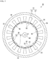
Fig. 1 is a cross-sectional view of an electric motor including an adhesively-laminated core for a stator according to one embodiment of the present invention. -
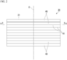
Fig. 2 is a side view of the laminated core for the stator. -
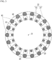
Fig. 3 is a cross-sectional view along line A-A inFig. 2 , showing an example of a formation pattern of adhesion parts in the adhesively-laminated core for the stator. -
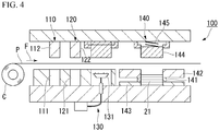
Fig. 4 is a side view of a manufacturing device used for manufacturing an example of the adhesively-laminated core for the stator. -
Fig. 5 is a graph showing a relationship between an average thickness t1 of an insulation coating and an average thickness t2 of the adhesion parts in the same example. -
Fig. 6 is a graph showing a relationship between the average thickness t1 of the insulation coating and an average tensile modulus of elasticity E of the adhesion parts in the same example. - Hereinafter, with reference to the drawings, an adhesively-laminated core for a stator and an electric motor including the adhesively-laminated core for the stator according to one embodiment of the present invention will be described. Also, in the present embodiment, as the electric motor, a motor, specifically, an AC motor, more specifically, a synchronous motor, and more specifically, a permanent magnetic electric motor will be described as an example. This type of motor is suitably adopted for, for example, an electric vehicle.
- As shown in
Fig. 1 , anelectric motor 10 includes astator 20, arotor 30, acase 50, and arotation shaft 60. Thestator 20 and therotor 30 are accommodated in thecase 50. Thestator 20 is fixed to thecase 50. - In the present embodiment, as the
electric motor 10, an inner rotor type electric motor in which therotor 30 is located inside thestator 20 in a radial direction thereof is adopted. However, as theelectric motor 10, an outer rotor type electric motor in which therotor 30 is located outside thestator 20 may be adopted. Further, in the present embodiment, theelectric motor 10 is a three-phase AC motor having 12 poles and 18 slots. However, the number of poles, the number of slots, the number of phases, and the like can be changed as appropriate. - The
electric motor 10 can rotate at a rotation speed of 1000 rpm by applying, for example, an excitation current having an effective value of 10 A and a frequency of 100 Hz to each phase. - The
stator 20 includes an adhesively-laminated core for a stator (hereinafter, a stator core) 21 and windings (not shown). - The
stator core 21 includes an annularcore back part 22 and a plurality oftooth parts 23. Below, a direction of a central axis O of the stator core 21 (or the core back part 22) is referred to as the axial direction, a radial direction (a direction orthogonal to the central axis O) of the stator core 21 (or the core back part 22) is referred to as the radial direction, and a circumferential direction (a direction revolving around the central axis O) of the stator core 21 (core back part 22) is referred to as the circumferential direction. - The
core back part 22 is formed in an annular shape in a plan view of thestator 20 from the axial direction. - The plurality of
tooth parts 23 extend inward in the radial direction (toward the central axis O of thecore back part 22 in the radial direction) from an inner circumference of thecore back part 22. The plurality oftooth parts 23 are disposed at equal angular intervals in the circumferential direction. In the present embodiment, 18tooth parts 23 are provided at every 20 degrees with respect to a central angle centered on the central axis O. The plurality oftooth parts 23 are formed to have the same shape and the same size as each other. Therefore, the plurality oftooth parts 23 have the same thickness dimension as each other. - The windings are wound around the
tooth parts 23. The windings may be concentrated windings or distributed windings. - The
rotor 30 is disposed inside the stator 20 (stator core 21) in the radial direction. Therotor 30 includes arotor core 31 and a plurality ofpermanent magnets 32. - The
rotor core 31 is formed in an annular shape (an annular ring shape) disposed coaxially with thestator 20. Therotation shaft 60 is disposed inside therotor core 31. Therotation shaft 60 is fixed to therotor core 31. - The plurality of
permanent magnets 32 are fixed to therotor core 31. In the present embodiment, a set of twopermanent magnets 32 form one magnetic pole. A plurality of sets ofpermanent magnets 32 are arranged at equal intervals in the circumferential direction. In the present embodiment, 12 sets (24 in total) ofpermanent magnets 32 are provided at every 30 degrees of the central angle centered on the central axis O. - In the present embodiment, an interior permanent magnet motor is adopted as a permanent magnetic electric motor. A plurality of through-
holes 33 that penetrate therotor core 31 in the axial direction are formed in therotor core 31. The plurality of through-holes 33 are provided to correspond to the plurality ofpermanent magnets 32. Eachpermanent magnet 32 is fixed to therotor core 31 in a state in which it is disposed in the corresponding through-hole 33. Fixing of eachpermanent magnet 32 to therotor core 31 can be realized, for example, by providing adhesion between an outer surface of thepermanent magnet 32 and an inner surface of the through-hole 33 with an adhesive or the like. Also, as the permanent magnet electric motor, a surface permanent magnet motor may be adopted instead of an interior permanent magnet type. - The
stator core 21 and therotor core 31 are both laminated cores. For example, as shown inFig. 2 , thestator core 21 is formed by laminating a plurality ofelectrical steel sheets 40 in the axial direction. - Further, a laminated thickness (the entire length along the central axis O) of each of the
stator core 21 and therotor core 31 is, for example, 50.0 mm. An outer diameter of thestator core 21 is, for example, 250.0 mm. An inner diameter of thestator core 21 is, for example, 165.0 mm. An outer diameter of therotor core 31 is, for example, 163.0 mm. An inner diameter of therotor core 31 is, for example, 30.0 mm. However, these values are examples, and the laminated thickness, the outer diameter, and the inner diameter of thestator core 21 and the laminated thickness, the outer diameter, and the inner diameter of therotor core 31 are not limited to only these values. Here, the inner diameter of thestator core 21 is measured with tips of thetooth parts 23 of thestator core 21 as a reference. That is, the inner diameter of thestator core 21 is a diameter of a virtual circle inscribed in the tips of all thetooth parts 23. - Each
electrical steel sheet 40 forming thestator core 21 and therotor core 31 is formed, for example, by punching an electrical steel sheet serving as a base material, etc. As theelectrical steel sheet 40, a known electrical steel sheet can be used. A chemical composition of theelectrical steel sheet 40 includes 2.5% to 3.9% Si, as shown below in units of mass%. By setting the chemical composition in these ranges, a yield strength YP of eachelectrical steel sheet 40 can be set to 380 MPa or more and 540 MPa or less. -
- Si: 2.5% to 3.9%
- Al: 0.001% to 3.0%
- Mn: 0.05% to 5.0%
- Remainder: Fe and impurities
- In the present embodiment, a non-grain-oriented electrical steel sheet is used as the
electrical steel sheet 40. As the non-grain-oriented electrical steel sheet, for example, a non-grain-oriented electrical steel strip of JIS C 2552:2014 can be adopted. However, as theelectrical steel sheet 40, a grain-oriented electrical steel sheet may be used instead of a non-grain-oriented electrical steel sheet. As the grain-oriented electrical steel sheet in this case, a grain-oriented electrical steel strip of JIS C 2553:2012 can be adopted. - Phosphate-based insulation coating are provided on both surfaces of the
electrical steel sheet 40 in order to improve workability of the stator core 21 (hereinafter, may be simply referred to as a "laminated core") and an iron loss of the laminated core. As a substance constituting the insulating coating, for example, (1) an inorganic compound, (2) an organic resin, (3) a mixture of an inorganic compound and an organic resin, and the like can be adopted. As the inorganic compound, for example, (1) a complex of dichromate and boric acid, (2) a complex of phosphate and silica, and the like can be exemplified. As the organic resin, an epoxy-based resin, an acrylic-based resin, an acrylic-styrene-based resin, a polyester-based resin, a silicone-based resin, a fluorine-based resin, and the like can be exemplified. - In order to ensure insulation performance between the
electrical steel sheets 40 laminated with each other, a lower limit of an average thickness t1 of the insulation coating (an average thickness per one surface of the electrical steel sheet 40) is preferably 0.3 µm, more preferably to 0.7 µm. - On the other hand, the insulation effect becomes saturated when the insulation coating becomes thicker. Further, as the insulation coating becomes thicker, a space factor of the
electrical steel sheet 40 in the laminated core decreases, and the performance of the laminated core deteriorates. Therefore, the insulation coating may be as thin as possible within a range in which the insulation performance can be ensured. An upper limit of the average thickness of the insulation coating (a thickness per one surface of the electrical steel sheet 40) is preferably 1.2 µm, more preferably 0.9 µm. - The average thickness t1 of the insulation coating is an average value of the entire laminated core. The thickness of the insulation coating is made to be almost the same over laminated positions thereof in the axial direction and a circumferential position around the central axis of the laminated core. For that reason, the average thickness t1 of the insulation coating can be set as a value measured at an upper end position of the laminated core.
- As the thickness of the
electrical steel sheet 40 becomes thinner, the proportion of theelectrical steel sheet 40 in the laminated core decreases. Further, as theelectrical steel sheet 40 becomes thinner, manufacturing costs of theelectrical steel sheet 40 increase. For that reason, a lower limit of an average sheet thickness of theelectrical steel sheet 40 is 0.15 mm, more preferably 0.18 mm in consideration of a decrease in the proportion of theelectrical steel sheet 40 in the laminated core and the manufacturing costs. - On the other hand, if the
electrical steel sheet 40 is too thick, the manufacturing costs become better, but an eddy current loss increases and a core loss deteriorates. For that reason, in consideration of the core loss and the manufacturing costs, an upper limit of the average sheet thickness of theelectrical steel sheet 40 is 0.35 mm, more preferably 0.30 mm. - 0.20 mm can be exemplified as one satisfying the above range of the average sheet thickness of the
electrical steel sheet 40. Also, the average thickness of theelectrical steel sheet 40 includes the thickness of the insulation coating. - As shown in
Fig. 3 , the plurality ofelectrical steel sheets 40 forming thestator core 21 are laminated, for example, via theadhesion parts 41 disposed in a shape of a plurality of points. Each of theadhesion parts 41 is formed of an adhesive that has been cured without being divided. For forming theadhesion part 41, for example, a thermosetting type adhesive by polymer bonding or the like is used. As such an adhesive, a radical polymerization type adhesive or the like can also be used in addition to a thermosetting type adhesive, and from the viewpoint of productivity, a room temperature curing type adhesive is preferably used. The room temperature curing type adhesive cures at 20°C to 30°C. As the room temperature curing type adhesive, an acrylic-based adhesive is preferable. A typical acrylic-based adhesive includes a second generation acrylic adhesive (SGA) and the like. Any of an anaerobic adhesive, an instant adhesive, and an elastomer-containing acrylic-based adhesive can be used within the range in which the effects of the present invention are not impaired. Also, the adhesive mentioned herein is an adhesive in a state before curing and becomes theadhesion part 41 after the adhesive is cured. - An average tensile modulus of elasticity E of the
adhesion part 41 at room temperature (20°C to 30°C) is in the range of 1500 MPa to 4500 MPa. If the average tensile modulus of elasticity E of theadhesion part 41 is less than 1500 MPa, there will be a problem that rigidity of the laminated core is lowered. For that reason, a lower limit of the average tensile modulus of elasticity E of theadhesion part 41 is 1500 MPa, more preferably 1800 MPa. On the contrary, if the average tensile modulus of elasticity E of theadhesion part 41 exceeds 4500 MPa, there will be a problem that the insulation coating formed on the surface of theelectrical steel sheet 40 is peeled off. For that reason, an upper limit of the average tensile modulus of elasticity E of theadhesion part 41 is 4500 MPa, more preferably 3650 MPa. - Also, the average tensile modulus of elasticity E is measured using a resonance method. Specifically, the tensile modulus of elasticity is measured in accordance with JIS R 1602:1995.
- More specifically, first, a sample for measurement (not shown) is manufactured. This sample is obtained by providing adhesion between two
electrical steel sheets 40 using an adhesive, which is a measurement target, and curing them to form theadhesion part 41. In a case in which the adhesive is a thermosetting type, the curing is performed by heating and pressurizing it under heating and pressurizing conditions in actual work. On the other hand, in a case in which the adhesive is a room temperature curing type, the curing is performed by pressurizing it at room temperature. - In addition, the tensile modulus of elasticity of this sample is measured using the resonance method. As described above, the method for measuring the tensile modulus of elasticity using the resonance method is performed in accordance with JIS R 1602:1995. Then, the tensile modulus of elasticity of the
adhesion part 41 alone can be obtained by removing an amount of influence of theelectrical steel sheet 40 itself from the tensile modulus of elasticity (measured value) of the sample by calculation. - Since the tensile modulus of elasticity obtained from the sample in this way is equal to an average value of the entire laminated core, this value is regarded as the average tensile modulus of elasticity E. The composition is set such that the average tensile modulus of elasticity E hardly changes at laminated positions in the axial direction or at circumferential positions around the central axis of the laminated core. For that reason, the average tensile modulus of elasticity E can be set to a value obtained by measuring the
adhesion part 41 after curing at the upper end position of the laminated core. - As a method of providing adhesion between the plurality of
electrical steel sheets 40, a method of adhering with which an adhesive is applied in a point shape to lower surfaces (surfaces on one side) of theelectrical steel sheets 40, then they are overlapped, and then one or both of heating and press-stacking are performed can be adopted. Also, a means in the case of heating may be any means such as a means for heating thestator core 21 in a high temperature bath or an electric furnace, or a method of directly energizing and heating thestator core 21. On the other hand, in a case in which a room temperature curing type adhesive is used, they are adhered only by press-stacking without heating. -
Fig. 3 shows an example of a formation pattern of theadhesion parts 41. Eachadhesion part 41 is formed in a shape having a plurality of points forming a circular shape. More specifically, in the core backpart 22, they are formed in point shapes having an average diameter of 12 mm at equal angular intervals in the circumferential direction thereof. Further, at a tip position of eachtooth part 23, theadhesion part 41 is formed in a point shape having an average diameter of 8 mm. The average diameters shown here are examples and can be appropriately selected from the range of 2 mm to 20 mm. In addition, the formation pattern ofFig. 3 is an example, and the number and arrangements of theadhesion parts 41 can be appropriately changed as needed. Also, the shape of eachadhesion part 41 is not limited to a circular shape and may be a rectangular shape or another polygonal shape if necessary. - The average thickness t2 of the
adhesion part 41 is 1.0 µm or more and 3.0 µm or less. When the average thickness t2 of theadhesion part 41 is less than 1.0 µm, a sufficient adhesion force cannot be secured. For that reason, a lower limit of the average thickness t2 of theadhesion part 41 is 1.0 µm, more preferably 1.2 µm. On the contrary, when the average thickness t2 of theadhesion part 41 becomes thicker than 3.0 µm, there will be problems such as a great increase in a strain amount of theelectrical steel sheet 40 due to shrinkage during thermosetting. For that reason, an upper limit of the average thickness t2 of theadhesion part 41 is 3.0 µm, more preferably 2.6 µm, and most preferably 1.8 µm. - The average thickness t2 of the
adhesion part 41 is an average value of the entire laminated core. The average thickness t2 of theadhesion parts 41 hardly changes at laminated positions in the axial direction and the circumferential position around the central axis of the laminated core. For that reason, the average thickness t2 of theadhesion parts 41 can be set as an average value of the numerical values measured at 10 or more points in the circumferential direction at the upper end position of the laminated core. - In addition, the average thickness t2 (µm) of the
adhesion part 41 and the average thickness t1 (µm) of the insulation coating satisfy the following Equation 1.
- Further, the average tensile modulus of elasticity E of the
adhesion parts 41 is 1500 MPa to 4500 MPa, and the average tensile modulus of elasticity E (MPa) and the average thickness t1 (µm) of the insulation coating satisfy the following Equation 2.
- First of all, regarding the above Equation 1, when the average thickness t2 of the
adhesion parts 41 is thinner than ―4.3×t1+3.6, the bond with the insulation coating is poor and the adhesion strength cannot be secured, and the mechanical strength of thestator core 21 cannot be maintained. On the other hand, when the average thickness t2 of theadhesion parts 41 becomes thicker than -4.3 × t1 + 6.9, close adhesion between the insulation coating and theelectrical steel sheet 40 tends to decrease due to the stress exerted by theadhesion parts 41 on the insulation coating. From the above, the average thickness t2 of theadhesion parts 41 is within the range of Equation 1. - Next, regarding the above Equation 2, when the average tensile modulus of elasticity E of the
adhesion parts 41 is lower than ―5000×t1+4500, the bond between theadhesion parts 41 and the insulation coating becomes poor and the adhesion strength cannot be maintained, and the mechanical strength of thestator core 21 may not be maintained. On the other hand, when the average tensile modulus of elasticity E of theadhesion parts 41 is higher than ―5000×t1+9000, the stress exerted by theadhesion parts 41 on the insulation coating may reduce the adhesion between the insulation coating and theelectrical steel sheet 40. From the above, the average tensile modulus of elasticity E of theadhesion parts 41 is preferably within the range of Equation 2. - In addition, the average thickness of the
adhesion parts 41 can be adjusted by changing, for example, an amount of an adhesive applied. Also, for example, in the case of a thermosetting type adhesive, the average tensile modulus of elasticity E of theadhesion parts 41 can be adjusted by changing one or both of the heating and pressurizing conditions and a type of a curing agent applied at the time of adhesion. - Further, for the above-mentioned reason, it is more preferable that the average thickness t1 (µm) and the average thickness t2 (µm) further satisfy the following Equations 3 and 4.


- Also, in the present embodiment, the plurality of electrical steel sheets forming the
rotor core 31 are fixed to each other by fastening 42 (dowels) shown inFig. 1 . However, the plurality of electrical steel sheets forming therotor core 31 may also have a laminated structure fixed by adhesion parts similarly to thestator core 21. Further, the laminated cores such as thestator core 21 and therotor core 31 may be formed by so-called turn-stacking. - Using a
manufacturing device 100 shown inFig. 4 , thestator core 21 was manufactured while changing various manufacturing conditions. - First, the
manufacturing device 100 will be described. In themanufacturing device 100, while feeding electrical steel sheets P from a coil C (a hoop) in a direction of arrow F, punching is performed a plurality of times by molds disposed on each stage to gradually form shapes of theelectrical steel sheets 40. Then, an adhesive is applied to lower surfaces of theelectrical steel sheets 40, and the punchedelectrical steel sheets 40 are laminated and pressed while raising a temperature. As a result, the adhesive is cured to form theadhesion parts 41, and thus the adhesion is completed. - As shown in
Fig. 4 , themanufacturing device 100 includes a first-stage punching station 110 at a position closest to the coil C, a second-stage punching station 120 adjacently disposed on a downstream side in a conveyance direction of the electrical steel sheet P from the punchingstation 110, and an adhesive-coating station 130 adjacently disposed on a further downstream side thereof from the punchingstation 120. - The punching
station 110 includes a fixedmold 111 disposed below the electrical steel sheet P and amovable mold 112 disposed above the electrical steel sheet P. - The punching
station 120 includes a fixedmold 121 disposed below the electrical steel sheet P and amovable mold 122 disposed above the electrical steel sheet P. - The adhesive-
coating station 130 includes anapplicator 131 including a plurality of injectors disposed in accordance with an adhesive coating pattern. - The
manufacturing device 100 further includes a stackingstation 140 at a downstream position from the adhesive-coating station 130. The stackingstation 140 includes aheating device 141, a fixed mold forouter shape 142, aheat insulation member 143, a movable mold forouter shape 144, and aspring 145. - The
heating device 141, the fixed mold forouter shape 142, and theheat insulation member 143 are disposed below the electrical steel sheet P. On the other hand, the movable mold forouter shape 144 and thespring 145 are disposed above the electrical steel sheet P. Also,reference numeral 21 indicates the stator core. - In the
manufacturing device 100 having the configuration described above, first, the electrical steel sheet P is sequentially sent out from the coil C in the direction of arrow F ofFig. 4 . Then, the electrical steel sheet P is, first, punched by the punchingstation 110. Subsequently, the electrical steel sheet P is punched by the punchingstation 120. By these punching processes, the shape of theelectrical steel sheet 40 having the core backpart 22 and the plurality oftooth parts 23 shown inFig. 3 is obtained on the electrical steel sheet P. However, since it is not completely punched at this point, the process proceeds to the next step in the direction of arrow F. In the adhesive-coating station 130 in the next step, the adhesive supplied from each of the injectors of theapplicator 131 is applied in a point shape. - Then, finally, the electrical steel sheet P is sent out to the stacking
station 140, punched out by the movable mold forouter shape 144, and laminated with high accuracy. At the time of this stacking, theelectrical steel sheet 40 receives a constant pressing force by thespring 145. - By sequentially repeating the punching process, the adhesive-coating process, and the stacking process as described above, a predetermined number of
electrical steel sheets 40 can be laminated. Further, the laminated core formed by stacking theelectrical steel sheets 40 in this way is heated to, for example, a temperature of 200°C by theheating device 141. This heating cures the adhesives to form theadhesion parts 41. - The
stator core 21 is completed through each of the above steps. - Using the
manufacturing device 100 described above, thestator cores 21 shown in No. 1 to No. 29 in Tables 1A and 1B were manufactured. The chemical components of theelectrical steel sheet 40 used in manufacturing eachstator core 21 were unified as follows. In addition, each component value indicates mass%. - Si: 3.1%
- Al: 0.7%
- Mn: 0.3%
- Remainder: Fe and impurities
- Specifically, a plurality of hoops (coils C) having the above chemical components were manufactured. A sheet thickness of a base steel of each hoop was unified to 0.20 mm. Then, an insulation coating treatment agent containing a metal phosphate and an acrylic resin emulsion was applied to each of these hoops and baked at 300°C to form insulation coatings on both front and back surfaces thereof. At that time, thicknesses of the insulation coatings were changed for each hoop. Specifically, as shown in Table 1A, each insulation coating was formed such that the average thickness t1 (µm) on one surface becomes 0.1 µm, 0.3 µm, 0.4 µm, 0.5 µm, 0.6 µm, 0.7 µm, 0.8 µm, 0.9 µm, 1.0 µm, 1.1 µm, 1.2 µm, 1.4 µm, and 1.5 µm.
- Then, the hoop set in the
manufacturing device 100 was changed, or the type of adhesive applied to theelectrical steel sheet 40, the type of curing agent added to the adhesive, the type of curing accelerator, and a coating film thickness were changed, whereby as shown in Table 1A, a plurality of laminated cores (stator cores 21) having different combinations of the average thickness t1 of the insulation coating, the type of adhesive, the average thickness t2 of theadhesion part 41, and the average tensile modulus of elasticity E were manufactured. - Specifically, first, one of the hoops was set in the
manufacturing device 100. Then, while feeding out the electrical steel sheet P from this hoop in the direction of arrow F inFig. 4 , a single-plate core (the electrical steel sheet 40), which has a ring shape with an outer diameter of 300 mm and an inner diameter of 240 mm and is provided with 18rectangular tooth parts 23 having a length of 30 mm and a width of 15 mm on an inner diameter side thereof was punched out. - Subsequently, while the punched single-plate core was sequentially fed, it was applied with the adhesive in a point shape at each position shown in
Fig. 3 , then laminated, heated while pressed at a predetermined pressure, and cured. The same work was repeated for 130 single-plate cores and one laminated core (the stator core 21) was manufactured. - By performing the same process for each hoop while changing each combination condition, 29 types of laminated cores shown in No. 1 to No. 29 in Tables 1A and 1B were manufactured.
- In addition, as the adhesive, a second generation acrylic-based adhesive was used as an elastomer-based adhesive in No. 1 to No. 27 and No. 29. On the other hand, in No. 28, a general-purpose anaerobic adhesive was used as an anaerobic adhesive.
- Further, the average thickness t2 of the
adhesion parts 41 was adjusted by changing the coating amount for each laminated core. Also, the average tensile modulus of elasticity E of theadhesion parts 41 was adjusted for each laminated core by changing one or both of the heating and pressurizing conditions and the type of curing agent applied at the time of adhesion at the stackingstation 140. - Each laminated core manufactured using the method described above was cut in a cross-section including their axes. Then, the average thickness t1 (µm) of the insulation coatings was determined. Further, in the
adhesion parts 41, the average thickness t2 (µm) and the average tensile modulus of elasticity E after curing were determined. The average tensile modulus of elasticity E was determined using the method described above. An outer diameter of each point-shaped adhesive after curing was 5 mm on average. - Then, the average thickness t1 (µm), the average thickness t2 (µm), and the average tensile modulus of elasticity E (MPa) were substituted into the above-mentioned Equations 1 and 2 and were determined whether or not Equations 1 and 2 were satisfied. The results are shown in Table 1A.
- Further, rigidity (mechanical strength) of the laminated core was also evaluated. The mechanical strength was evaluated with a magnitude of a load when a cutting edge with a width of 20 mm, a tip angle of 10°, and 0.15 mm R was gradually pressed against a laminated part (between a pair of
electrical steel sheets 40 adjacent to each other) of the laminated core while increasing the load to generate cracks. A higher load is more preferable, and the one having 4 MPa or more was judged to be good or excellent. In the mechanical strength of the laminated core in Table 1B, "excellent" indicates that high mechanical strength is secured, "good" indicates that necessary and sufficient mechanical strength is secured, and "poor" indicates that the minimum required mechanical strength is not secured. - Further, presence or absence of peeling of the insulation coating was also evaluated. Regarding the presence or absence of peeling of the insulation coating in Table 1B, "absence" indicates a state in which there is no peeling, and "presence" indicates a state in which peeling occurs in places.
- Furthermore, the magnetic properties of the laminated core were also evaluated. When the magnetic properties were evaluated, the number of laminated sheets was set to 20, winding was performed after covering the laminated core with insulating paper, and the core loss (W15/50 in Table 1B) was measured at a frequency of 50 Hz and a magnetic flux density of 1.5 Tesla. Here, the number of lamination of the
electrical steel sheets 40 when the evaluation of the magnetic properties was performed was set to 20 because almost the same results as in the case of 130 can be obtained. - A lower core loss (W15/50 in Table 1B) is more preferable, and the one having 2.70 or less was decided to be good or excellent. In the magnetic properties of the laminated cores in Table 1B, "excellent" indicates that high magnetic properties can be secured, "good" indicates that necessary and sufficient magnetic properties are secured, and "poor" indicates that the minimum required magnetic properties are not secured.
- Further,
Fig. 5 shows a relationship between the average thickness t1 of the insulation coatings and the average thickness t2 of theadhesion parts 41 shown in Table 1A. Similarly,Fig. 6 shows a relationship between the average thickness t1 of the insulation coatings and the average tensile modulus of elasticity E of theadhesion parts 41 shown in Table 1A. - As shown in Tables 1A and 1B, in the comparative examples shown in Nos. 16 and 17, the average thickness t1 of the insulation coatings was thin and the magnetic properties deteriorated.
- Also, in the comparative example shown in No. 18, unevenness of the insulation coatings could not be filled, and the mechanical strength decreased.
- Also, in the comparative example shown in No. 19, the average thickness t2 of the
adhesion parts 41 was thick, the proportion of theelectrical steel sheets 40 in the laminated core decreased, and the magnetic properties deteriorated. - Also, in the comparative example shown in No. 20, the unevenness of the insulation coatings could not be filled, and the mechanical strength decreased.
- Also, in the comparative example shown in No. 21, the average thickness t2 of the
adhesion parts 41 was thick, the proportion of theelectrical steel sheets 40 in the laminated core decreased, and the magnetic properties deteriorated. - Also, in the comparative example shown in No. 22, the average thickness t2 of the
adhesion parts 41 was thin, the adhesion strength was lowered, and the mechanical strength was lowered. - Also, in the comparative example shown in No. 23, the average thickness t2 of the
adhesion parts 41 was thick, the proportion of theelectrical steel sheets 40 in the laminated core decreased, and the magnetic properties deteriorated. - Also, in the comparative example shown in No. 24, the average thickness t2 of the
adhesion part 41 was thin, the adhesion strength was lowered, and the mechanical strength was lowered. - Also, in the comparative example shown in No. 25, since the average thickness t1 of the insulation coatings was relatively thick and the adhesion tended to decrease, the upper limit of the average thickness t2 of the adhesion parts 41 (the upper limit of the average tensile modulus of elasticity E) substantially decreased, and the mechanical strength decreased.
- Also, in the comparative example shown in No. 26, the average thickness t1 of the insulation coatings was thick, the adhesion was lowered, and the coatings were peeled off.
- Also, in the comparative example shown in No. 27, the average thickness t1 of the insulation coatings was thick, the adhesion was lowered, and the coatings were peeled off.
- Further, although the comparative example shown in No. 28 was in the region shown in each of
Figs. 5 and 6 , the adhesive used for adhesion was an anaerobic adhesive and did not have a sea-island structure, and thus the curedadhesion parts 41 generated strain in theelectrical steel sheets 40, and due to the strain of theelectrical steel sheets 40, the magnetic properties deteriorated. - On the other hand, in Nos. 1 to 15 and 29, which are the examples, it was confirmed that the rigidity (mechanical strength) of the laminated core was high, the insulation coatings were not peeled off, and the magnetic properties (W15/50) had desired performance.
- Among these examples, in particular, in Nos. 3, 6, 8, 10, 12, 14, and 15, since the average thickness t2 of the
adhesion parts 41 was 1.8 µm or less, even higher magnetic properties were be obtained than in other examples. - Further, among these, in Nos. 6, 8 and 10, the average thickness t1 of the insulation coatings also satisfies the range of 0.7 µm to 0.9 µm. For that reason, optimization has been performed with respect to securing of insulation performance is deterioration of performance as a laminated core, which is the most preferable among all the examples.
- Also, in the present examples, a thermosetting type adhesive was applied, but there is no difference in the basic tendency even with a room temperature curing type adhesive.
- The embodiment and the examples of the present invention have been described above. However, the technical scope of the present invention is not limited to the above-described embodiment and the examples, and various changes can be added thereto without departing from the spirit of the present invention.
- For example, the shape of the
stator core 21 is not limited to the form shown in the above embodiment. Specifically, dimensions of the outer diameter and the inner diameter of thestator core 21, the laminated thickness, the number of slots, a dimensional ratio of thetooth part 23 between in the circumferential direction and in the radial direction, a dimensional ratio in the radial direction between thetooth part 23 and the core backpart 22, and the like can be arbitrarily designed in accordance with desired properties of the electric motor. - In the
rotor 30 of the above embodiment, the set of twopermanent magnets 32 form one magnetic pole, but the present invention is not limited thereto. For example, onepermanent magnet 32 may form one magnetic pole, or three or morepermanent magnets 32 may form one magnetic pole. - In the above-described embodiment, the permanent magnetic electric motor has been described as an example of the
electric motor 10, but as illustrated below, the structure of theelectric motor 10 is not limited thereto, and various known structures not illustrated below can also be adopted. - In the above-described embodiment, the permanent magnetic electric motor has been described as an example of the
electric motor 10, but the present invention is not limited thereto. For example, theelectric motor 10 may be a reluctance motor or an electromagnet field motor (a wound-field motor). - In the above-described embodiment, the synchronous motor has been described as an example of the AC motor, but the present invention is not limited thereto. For example, the
electric motor 10 may be an induction motor. - In the above-described embodiment, the AC motor has been described as an example of the
electric motor 10, but the present invention is not limited thereto. For example, theelectric motor 10 may be a DC motor. - In the above-described embodiment, the motor has been described as an example of the
electric motor 10, but the present invention is not limited thereto. For example, theelectric motor 10 may be a generator. - In addition, within the range not departing from the spirit of the present invention, it is possible to replace the components in the embodiment with well-known components as appropriate, and the above-mentioned modified examples may be combined with each other as appropriate.
- According to the present invention, an adhesively-laminated core for a stator that can both prevent peeling of an insulation coating and inhibit deterioration of magnetic properties due to a stress applied to an electrical steel sheet by an adhesion part, and an electric motor including the adhesively-laminated core for the stator can be provided. Therefore, it provides great industrial applicability.
-
- 10
- Electric motor
- 21
- Laminated core (adhesively-laminated core for stator)
- 40
- Electrical steel sheet
- 41
- Adhesion part
| No. | Electrical steel sheet | Insulation coating | Adhesion part | ||||
| Average sheet thickness (mm) | Average thickness t1 (µm) | Adhesive used | Average thickness t2 (µm) | Average tensile modulus of elasticity (MPa) | Whether or not to satisfy Equation 1(∗a) | Whether or not to satisfy Equation 2(∗b) | |
| 1 | 0.20 | 0.3 | Elastomer-based | 2.4 | 3600 | Satisfied | Satisfied |
| 2 | 0.20 | 0.3 | Elastomer-based | 2.8 | 4200 | Satisfied | Satisfied |
| 3 | 0.20 | 0.5 | Elastomer-based | 1.5 | 2300 | Satisfied | Satisfied |
| 4 | 0.20 | 0.5 | Elastomer-based | 2.1 | 3200 | Satisfied | Satisfied |
| 5 | 0.20 | 0.5 | Elastomer-based | 2.7 | 4100 | Satisfied | Satisfied |
| 6 | 0.20 | 0.7 | Elastomer-based | 1.6 | 2400 | Satisfied | Satisfied |
| 7 | 0.20 | 0.7 | Elastomer-based | 2.3 | 3500 | Satisfied | Satisfied |
| 8 | 0.20 | 0.8 | Elastomer-based | 1.4 | 2100 | Satisfied | Satisfied |
| 9 | 0.20 | 0.8 | Elastomer-based | 2.7 | 4100 | Satisfied | Satisfied |
| 10 | 0.20 | 0.9 | Elastomer-based | 1.8 | 2700 | Satisfied | Satisfied |
| 11 | 0.20 | 0.9 | Elastomer-based | 2.3 | 3500 | Satisfied | Satisfied |
| 12 | 0.20 | 1.0 | Elastomer-based | 1.6 | 2400 | Satisfied | Satisfied |
| 13 | 0.20 | 1.0 | Elastomer-based | 2.2 | 3300 | Satisfied | Satisfied |
| 14 | 0.20 | 1.2 | Elastomer-based | 1.1 | 2000 | Satisfied | Satisfied |
| 15 | 0.20 | 1.2 | Elastomer-based | 1.3 | 2000 | Satisfied | Satisfied |
| 16 | 0.20 | 0.1 | Elastomer-based | 1.2 | 1800 | Unsatisfied | Unsatisfied |
| 17 | 0.20 | 0.1 | Elastomer-based | 2.1 | 3200 | Unsatisfied | Unsatisfied |
| 18 | 0.20 | 0.3 | Elastomer-based | 1.3 | 2000 | Unsatisfied | Unsatisfied |
| 19 | 0.20 | 0.3 | Elastomer-based | 3.4 | 5100 | Satisfied | Satisfied |
| 20 | 0.20 | 0.4 | Elastomer-based | 1.2 | 1800 | Unsatisfied | Unsatisfied |
| 21 | 0.20 | 0.6 | Elastomer-based | 3.6 | 5400 | Satisfied | Satisfied |
| 22 | 0.20 | 0.8 | Elastomer-based | 0.5 | 800 | Satisfied | Satisfied |
| 23 | 0.20 | 0.8 | Elastomer-based | 3.2 | 4800 | Satisfied | Satisfied |
| 24 | 0.20 | 1.1 | Elastomer-based | 0.7 | 1100 | Satisfied | Satisfied |
| 25 | 0.20 | 1.1 | Elastomer-based | 2.6 | 3900 | Unsatisfied | Unsatisfied |
| 26 | 0.20 | 1.5 | Elastomer-based | 0.8 | 1200 | Unsatisfied | Unsatisfied |
| 27 | 0.20 | 1.4 | Elastomer-based | 2.8 | 4200 | Unsatisfied | Unsatisfied |
| 28 | 0.20 | 0.8 | Anaerobic adhesive | 2.8 | 4200 | Satisfied | Satisfied |
| 29 | 0.20 | 1.1 | Elastomer-based | 2.0 | 4200 | Satisfied | Unsatisfied |
| No. | Mechanical strength | Presence or absence of peeling of insulation coating | Magnetic properties | Example / Comparative example | ||
| (MPa) | Decision | W15/50 | Decision | |||
| 1 | 6 | Good | Absence | 2.53 | Good | Example |
| 2 | 8 | Good | Absence | 2.56 | Good | Example |
| 3 | 7 | Good | Absence | 2.50 | Excellent | Example |
| 4 | 6 | Good | Absence | 2.56 | Good | Example |
| 5 | 10 | Excellent | Absence | 2.58 | Good | Example |
| 6 | 10 | Excellent | Absence | 2.49 | Excellent | Example |
| 7 | 5 | Good | Absence | 2.59 | Good | Example |
| 8 | 9 | Excellent | Absence | 2.50 | Excellent | Example |
| 9 | 5 | Good | Absence | 2.53 | Good | Example |
| 10 | 9 | Excellent | Absence | 2.51 | Excellent | Example |
| 11 | 7 | Good | Absence | 2.57 | Good | Example |
| 12 | 6 | Good | Absence | 2.50 | Excellent | Example |
| 13 | 6 | Good | Absence | 2.58 | Good | Example |
| 14 | 7 | Good | Absence | 2.59 | Excellent | Example |
| 15 | 5 | Good | Absence | 2.51 | Excellent | Example |
| 16 | 6 | Good | Absence | 2.74 | Poor | Comparative example |
| 17 | 9 | Excellent | Absence | 2.79 | Poor | Comparative example |
| 18 | 1 | Poor | Absence | 2.63 | Good | Comparative example |
| 19 | 10 | Excellent | Presence | 2.87 | Poor | Comparative example |
| 20 | 2 | Poor | Absence | 2.58 | Good | Comparative example |
| 21 | 10 | Excellent | Presence | 2.74 | Poor | Comparative example |
| 22 | 1 | Poor | Absence | 2.58 | Good | Comparative example |
| 23 | 9 | Excellent | Presence | 2.81 | Poor | Comparative example |
| 24 | 1 | Poor | Absence | 2.57 | Good | Comparative example |
| 25 | 2 | Poor | Absence | 2.56 | Good | Comparative example |
| 26 | 7 | Good | Presence | 2.57 | Good | Comparative example |
| 27 | 8 | Good | Presence | 2.53 | Good | Comparative example |
| 28 | 6 | Good | Presence | 2.83 | Poor | Comparative example |
| 29 | 5 | Good | Absence | 2.54 | Good | Example |
Claims (7)
- An adhesively-laminated core for a stator comprising:a plurality of electrical steel sheets which have phosphate-based insulation coatings on surfaces thereof and are overlapped coaxially with each other; andadhesion parts provided between the respective electrical steel sheets,wherein an average thickness of the insulation coatings is 0.3 µm to 1.2 µm,an average thickness of the adhesion parts is 1.0 µm to 3.0 µm, andin a case where the average thickness of the insulation coating is defined as t1 in a unit of µm, and the average thickness of the adhesion parts is defined as t2 in a unit of µm, the following Equation 1 is satisfied.

- The adhesively-laminated core for the stator according to claim 1,wherein the average thickness t1 is 0.7 µm to 0.9 µm, andthe average thickness t2 is 1.2 µm to 2.6 µm.
- The adhesively-laminated core for the stator according to claim 1 or 2,wherein an average tensile modulus of elasticity E of the adhesion parts is 1500 MPa to 4500 MPa, andthe average tensile modulus of elasticity E (MPa) and the average thickness t1 (µm) of the insulation coating satisfy the following Equation 2.

- The adhesively-laminated core for the stator according to claim 3,wherein the average tensile modulus of elasticity E is 1800 MPa to 3650 MPa, andthe average thickness t1 is 0.7 µm to 0.9 µm.
- The adhesively-laminated core for the stator according to any one of claims 1 to 4, wherein the adhesion parts are room temperature curing type acrylic-based adhesives each containing SGA made of an elastomer-containing acrylic-based adhesive.
- The adhesively-laminated core for the stator according to any one of claims 1 to 5, wherein an average sheet thickness of the electrical steel sheets is 0.15 mm to 0.35 mm.
- An electric motor comprising the adhesively-laminated core for the stator according to any one of claims 1 to 6.
Priority Applications (1)
| Application Number | Priority Date | Filing Date | Title |
|---|---|---|---|
| RS20250894A RS67189B1 (en) | 2018-12-17 | 2019-12-17 | Adhesively laminated core for stator and electric motor |
Applications Claiming Priority (2)
| Application Number | Priority Date | Filing Date | Title |
|---|---|---|---|
| JP2018235864 | 2018-12-17 | ||
| PCT/JP2019/049266 WO2020129925A1 (en) | 2018-12-17 | 2019-12-17 | Stator adhesive laminated core and rotating electric machine |
Publications (3)
| Publication Number | Publication Date |
|---|---|
| EP3902121A1 true EP3902121A1 (en) | 2021-10-27 |
| EP3902121A4 EP3902121A4 (en) | 2022-11-30 |
| EP3902121B1 EP3902121B1 (en) | 2025-08-13 |
Family
ID=71101789
Family Applications (1)
| Application Number | Title | Priority Date | Filing Date |
|---|---|---|---|
| EP19899295.0A Active EP3902121B1 (en) | 2018-12-17 | 2019-12-17 | Adhesively laminated core for stator and electric motor |
Country Status (12)
| Country | Link |
|---|---|
| US (1) | US12154711B2 (en) |
| EP (1) | EP3902121B1 (en) |
| JP (2) | JP7486434B2 (en) |
| KR (1) | KR102607691B1 (en) |
| CN (1) | CN113169639B (en) |
| EA (1) | EA202192059A1 (en) |
| MY (1) | MY208350A (en) |
| PL (1) | PL3902121T3 (en) |
| RS (1) | RS67189B1 (en) |
| SG (1) | SG11202108888RA (en) |
| TW (1) | TWI717940B (en) |
| WO (1) | WO2020129925A1 (en) |
Families Citing this family (17)
| Publication number | Priority date | Publication date | Assignee | Title |
|---|---|---|---|---|
| JP7412351B2 (en) | 2018-12-17 | 2024-01-12 | 日本製鉄株式会社 | Laminated core and rotating electrical machinery |
| EA202192064A1 (en) | 2018-12-17 | 2021-11-24 | Ниппон Стил Корпорейшн | CORE AND ELECTRIC MOTOR |
| JP7515403B2 (en) | 2018-12-17 | 2024-07-12 | 日本製鉄株式会社 | Adhesive laminated core for stator, manufacturing method thereof, and rotating electric machine |
| RS65860B1 (en) | 2018-12-17 | 2024-09-30 | Nippon Steel Corp | Laminated core and rotating electric machine |
| EA202192075A1 (en) | 2018-12-17 | 2021-11-23 | Ниппон Стил Корпорейшн | CORE AND ELECTRIC MOTOR |
| JP7311791B2 (en) | 2018-12-17 | 2023-07-20 | 日本製鉄株式会社 | Laminated core and rotating electric machine |
| SG11202108979XA (en) | 2018-12-17 | 2021-09-29 | Nippon Steel Corp | Laminated core and electric motor |
| SG11202108989YA (en) | 2018-12-17 | 2021-09-29 | Nippon Steel Corp | Laminated core, method of manufacturing same, and electric motor |
| CN113169641B (en) | 2018-12-17 | 2024-10-18 | 日本制铁株式会社 | Laminated iron core, method for manufacturing laminated iron core, and rotating electrical machine |
| RS67413B1 (en) | 2018-12-17 | 2025-12-31 | Nippon Steel Corp | Adhesively laminated core for stator, method of manufacturing the same, and electric motor |
| US12074476B2 (en) | 2018-12-17 | 2024-08-27 | Nippon Steel Corporation | Adhesively-laminated core for stator and electric motor |
| US11990795B2 (en) | 2018-12-17 | 2024-05-21 | Nippon Steel Corporation | Adhesively-laminated core for stator, method of manufacturing same, and electric motor |
| CA3131358A1 (en) | 2018-12-17 | 2020-06-25 | Nippon Steel Corporation | Laminated core, core block, electric motor and method of producing core block |
| EA202192076A1 (en) | 2018-12-17 | 2021-11-10 | Ниппон Стил Корпорейшн | LAMINATED CORE AND ELECTRIC MOTOR |
| PL3902113T3 (en) | 2018-12-17 | 2024-11-25 | Nippon Steel Corporation | Laminated core and electric motor |
| TWI724690B (en) | 2018-12-17 | 2021-04-11 | 日商日本製鐵股份有限公司 | Laminated iron core and rotating electric machine |
| TWI837708B (en) * | 2022-06-20 | 2024-04-01 | 大銀微系統股份有限公司 | Motor rotor core structure |
Family Cites Families (194)
| Publication number | Priority date | Publication date | Assignee | Title |
|---|---|---|---|---|
| US3386058A (en) | 1966-11-21 | 1968-05-28 | Westinghouse Electric Corp | Inductive assembly with supporting means |
| US4025379A (en) | 1973-05-03 | 1977-05-24 | Whetstone Clayton N | Method of making laminated magnetic material |
| US4103195A (en) | 1976-08-11 | 1978-07-25 | General Electric Company | Bonded laminations forming a stator core |
| JPS5665326A (en) | 1979-10-29 | 1981-06-03 | Tdk Corp | Magnetic core for magnetic head |
| JPS576427A (en) | 1980-06-11 | 1982-01-13 | Canon Inc | Manufacture of magnetic core |
| US4413406A (en) | 1981-03-19 | 1983-11-08 | General Electric Company | Processing amorphous metal into packets by bonding with low melting point material |
| JPS60170681A (en) | 1984-02-16 | 1985-09-04 | Nippon Synthetic Chem Ind Co Ltd:The | adhesive composition |
| JPS60186834A (en) | 1984-03-07 | 1985-09-24 | Toray Ind Inc | Photosensitive resin plate material developable with water |
| JPS60186834U (en) | 1984-05-18 | 1985-12-11 | 株式会社東芝 | Stator core of rotating electric machine |
| JPS629951A (en) | 1985-07-08 | 1987-01-17 | 新日本製鐵株式会社 | Laminated steel plate having excellent moldability |
| JPS63207639A (en) | 1987-02-25 | 1988-08-29 | 日新製鋼株式会社 | Vibration-damping steel plate and manufacture thereof |
| JPH01168777A (en) * | 1987-12-25 | 1989-07-04 | Konishi Kk | Adhesive composition |
| JPH03124247A (en) | 1989-10-05 | 1991-05-27 | Aichi Emerson Electric Co Ltd | Stator for rotary electric machine |
| JPH03247683A (en) | 1990-02-23 | 1991-11-05 | Sumitomo Chem Co Ltd | Acrylic adhesive composition |
| JPH0428743U (en) | 1990-05-22 | 1992-03-06 | ||
| JP2897344B2 (en) | 1990-05-23 | 1999-05-31 | 住友化学工業株式会社 | Thermoplastic resin composition |
| JPH08996B2 (en) | 1991-01-24 | 1996-01-10 | 新日本製鐵株式会社 | Method for manufacturing surface-treated steel sheet with excellent weldability and paint adhesion |
| US5448119A (en) | 1991-03-29 | 1995-09-05 | Nagano Nidec Corporation | Spindle motor |
| US5142178A (en) | 1991-04-12 | 1992-08-25 | Emerson Electric Co. | Apparatus for aligning stacked laminations of a dynamoelectric machine |
| JPH0614481A (en) | 1992-06-25 | 1994-01-21 | Mitsubishi Electric Corp | Armature iron core |
| JPH07118620A (en) | 1993-10-22 | 1995-05-09 | Nippon Zeon Co Ltd | Epoxy adhesive composition |
| JPH07298567A (en) | 1994-04-26 | 1995-11-10 | Honda Motor Co Ltd | Heater for bonding laminated steel sheets |
| JPH08259899A (en) | 1995-03-23 | 1996-10-08 | Three Bond Co Ltd | Cyanoacrylate adhesive composition |
| JP3266448B2 (en) * | 1995-03-27 | 2002-03-18 | 株式会社リコー | Rotary device of brushless motor |
| JPH10304610A (en) | 1997-04-22 | 1998-11-13 | Toshiba Corp | Method for manufacturing permanent magnet rotor and blank for permanent magnet rotor |
| JP3369941B2 (en) | 1997-11-27 | 2003-01-20 | 日本鋼管株式会社 | Manufacturing method of electrical steel sheet for bonded iron core with excellent adhesive strength, corrosion resistance and blocking resistance |
| JP2000050539A (en) | 1998-07-28 | 2000-02-18 | Toshiba Corp | Stator core of rotating electric machine, steel plate part for stator core, method of manufacturing stator core, and method of manufacturing steel plate part for stator core |
| JP2000152570A (en) | 1998-11-06 | 2000-05-30 | Toshiba Corp | Manufacturing method of magnet core |
| JP2001115125A (en) | 1999-10-01 | 2001-04-24 | Three M Innovative Properties Co | Neodymium magnet adhesive and motor |
| FR2803126B1 (en) | 1999-12-23 | 2006-04-14 | Valeo Equip Electr Moteur | ALTERNATOR FOR STATOR VEHICLE WITH LITTLE NOISE OF MAGNETIC NOISE |
| JP2001251828A (en) | 2000-03-02 | 2001-09-14 | Moric Co Ltd | Multipole magnet generator for internal combustion engines |
| JP2002078257A (en) | 2000-08-24 | 2002-03-15 | Mitsubishi Electric Corp | Motor and its rotor |
| JP4665298B2 (en) * | 2000-08-25 | 2011-04-06 | 東レ株式会社 | TAPE WITH ADHESIVE FOR SEMICONDUCTOR DEVICE, COPPER-CLAD LAMINATE USING SAME, SEMICONDUCTOR CONNECTION BOARD AND SEMICONDUCTOR DEVICE |
| US6784587B2 (en) | 2000-08-29 | 2004-08-31 | Mitsubishi Denki Kabushiki Kaisha | Stacked stator core and method of manufacturing thereof, and rotary motor and method of manufacturing thereof |
| JP2002164224A (en) | 2000-08-30 | 2002-06-07 | Mitsui Chemicals Inc | Magnetic substrate and method for producing the same |
| JP4020236B2 (en) | 2000-09-18 | 2007-12-12 | 電気化学工業株式会社 | Curable resin composition, cured body, adhesive composition, and joined body |
| JP2002105283A (en) | 2000-09-28 | 2002-04-10 | Nhk Spring Co Ltd | Epoxy resin dispersion, copper-clad laminate and copper-clad metal substrate using the same |
| JP2002125341A (en) | 2000-10-16 | 2002-04-26 | Denki Kagaku Kogyo Kk | Stator and motor using the same |
| JP2002151335A (en) | 2000-11-10 | 2002-05-24 | Nippon Steel Corp | Laminated iron core excellent in iron loss characteristics and method of manufacturing the same |
| JP3725776B2 (en) | 2000-11-10 | 2005-12-14 | 新日本製鐵株式会社 | Method for manufacturing laminated iron core and apparatus for manufacturing the same |
| EP1241773B1 (en) | 2001-03-14 | 2012-09-12 | Nissan Motor Co., Ltd. | Rotating electrical machine with air-gap sleeve |
| JP4076323B2 (en) * | 2001-05-08 | 2008-04-16 | 電気化学工業株式会社 | Curable resin composition, cured body, adhesive composition, and joined body |
| JP4018885B2 (en) | 2001-05-25 | 2007-12-05 | 株式会社三井ハイテック | Laminated iron core |
| KR100526286B1 (en) * | 2001-08-17 | 2005-11-08 | 제이에프이 스틸 가부시키가이샤 | Manufacturing apparatus and manufacturing method for laminated core |
| JP3594003B2 (en) | 2001-08-28 | 2004-11-24 | 日産自動車株式会社 | Rotating electric machine and method of manufacturing the same |
| JP2003199303A (en) | 2001-12-27 | 2003-07-11 | Matsushita Electric Ind Co Ltd | Motor manufacturing method |
| JP4165072B2 (en) | 2002-01-15 | 2008-10-15 | 日立化成工業株式会社 | Adhesive composition, adhesive film, wiring board for semiconductor mounting, semiconductor device and manufacturing method thereof |
| JP2003219585A (en) | 2002-01-22 | 2003-07-31 | Mitsubishi Electric Corp | Laminated core and method of manufacturing the same |
| JP3771933B2 (en) | 2002-03-08 | 2006-05-10 | Jfeスチール株式会社 | LAMINATED CORE MATERIAL AND METHOD FOR PRODUCING THE SAME |
| JP2003284274A (en) | 2002-03-22 | 2003-10-03 | Nippon Steel Corp | Permanent magnet synchronous motor rotor |
| JP2004088970A (en) * | 2002-08-29 | 2004-03-18 | Hitachi Ltd | Laminated core, rotating electric machine and transformer using the same |
| JP2004111509A (en) | 2002-09-17 | 2004-04-08 | Nippon Steel Corp | Laminated iron core excellent in iron loss characteristics and method of manufacturing the same |
| JP4222000B2 (en) | 2002-10-29 | 2009-02-12 | Nok株式会社 | Magnetic encoder |
| JP3791492B2 (en) | 2002-12-25 | 2006-06-28 | 株式会社日立製作所 | Rotating electric machine, electric vehicle, and resin insert molding method |
| CN100476030C (en) | 2003-02-03 | 2009-04-08 | 新日本制铁株式会社 | Surface-coated electromagnetic steel sheet for adhesion |
| JP4987216B2 (en) | 2003-06-25 | 2012-07-25 | Jfeスチール株式会社 | Laminated core with excellent dimensional accuracy and manufacturing method thereof |
| WO2005025032A1 (en) | 2003-09-03 | 2005-03-17 | Mitsuba Corporation | Electric motor |
| JP2005269732A (en) | 2004-03-17 | 2005-09-29 | Nippon Steel Corp | Iron core manufacturing method and apparatus suitable for the method |
| JP2005268589A (en) | 2004-03-19 | 2005-09-29 | Nippon Steel Corp | Simple manufacturing method of magnetic member for energy conversion equipment |
| JP4548049B2 (en) | 2004-09-01 | 2010-09-22 | 株式会社日立製作所 | Rotating electric machine |
| JP4498154B2 (en) | 2005-01-27 | 2010-07-07 | ファナック株式会社 | Motor manufacturing method and motor manufacturing apparatus |
| JP2006254530A (en) | 2005-03-08 | 2006-09-21 | Mitsubishi Electric Corp | Electric motor |
| JP2006288114A (en) | 2005-04-01 | 2006-10-19 | Mitsui High Tec Inc | Laminated iron core and method for producing laminated iron core |
| JP2006353001A (en) | 2005-06-15 | 2006-12-28 | Japan Servo Co Ltd | Laminated iron core and method and apparatus for manufacturing the same |
| JP4687289B2 (en) | 2005-07-08 | 2011-05-25 | 東洋紡績株式会社 | Polyamide-based mixed resin laminated film roll and manufacturing method thereof |
| JP4586669B2 (en) | 2005-08-01 | 2010-11-24 | 住友金属工業株式会社 | Method for producing non-oriented electrical steel sheet for rotor |
| JP2007053896A (en) | 2005-08-17 | 2007-03-01 | Minebea Co Ltd | Stator unit and manufacturing method thereof |
| JP4236056B2 (en) | 2006-02-08 | 2009-03-11 | 三菱電機株式会社 | Magnet generator |
| KR100808194B1 (en) | 2006-05-19 | 2008-02-29 | 엘지전자 주식회사 | Stator of outer rotor type motor |
| JP5309431B2 (en) * | 2006-08-04 | 2013-10-09 | 新日鐵住金株式会社 | Laminated steel sheet of electromagnetic steel having high resistance between steel sheets on shear plane of steel sheet and caulking method thereof |
| JP4938389B2 (en) | 2006-09-06 | 2012-05-23 | 三菱電機株式会社 | Laminated core and stator |
| CN101523696B (en) | 2006-10-13 | 2012-12-05 | 株式会社三井高科技 | Laminated iron core and manufacturing method thereof |
| CN101675134B (en) | 2007-02-06 | 2014-06-18 | 奥地利西门子公司 | Insulating material for electrical machines |
| ITMI20070508A1 (en) | 2007-03-14 | 2008-09-15 | Corrada Spa | LAMINAR ARTICLE FOR ELECTRICAL USE PROCEDURE AND MACHINES TO REALIZE THE LAMINAR ARTICLE |
| JP5129810B2 (en) | 2007-05-09 | 2013-01-30 | 株式会社三井ハイテック | Laminated iron core and method for manufacturing the same |
| JP4376957B2 (en) | 2007-07-19 | 2009-12-02 | 積水化学工業株式会社 | Adhesive for electronic parts |
| JP2009072035A (en) | 2007-09-18 | 2009-04-02 | Meidensha Corp | Rotor core of rotating electrical machine |
| JP5211651B2 (en) | 2007-11-15 | 2013-06-12 | パナソニック株式会社 | Motor and electronic device using the same |
| JP5172367B2 (en) | 2008-01-23 | 2013-03-27 | 三菱電機株式会社 | Laminated core, laminated core manufacturing method, laminated core manufacturing apparatus, and stator |
| CA2715384C (en) | 2008-02-15 | 2016-02-09 | Kuraray Co., Ltd. | Curable resin composition and cured resin |
| JP5428218B2 (en) | 2008-06-23 | 2014-02-26 | 富士電機株式会社 | Rotor structure of permanent magnet type rotating electrical machine |
| JP2010081659A (en) | 2008-09-24 | 2010-04-08 | Hitachi Ltd | Electric motor and electric compressor using the same |
| WO2010082482A1 (en) | 2009-01-15 | 2010-07-22 | 株式会社カネカ | Curable composition, cured object obtained therefrom, and process for producing same |
| JP5084770B2 (en) | 2009-03-13 | 2012-11-28 | 三菱電機株式会社 | Electric motor, compressor and air conditioner |
| GB2480958B (en) | 2009-03-26 | 2014-06-25 | Vacuumschmelze Gmbh & Co Kg | Laminated core with soft-magnetic material and method for joining core laminations by adhesive force to form a soft-magnetic laminated core |
| JP2010239691A (en) | 2009-03-30 | 2010-10-21 | Denso Corp | Rotating electric machine stator and rotating electric machine |
| JP5444812B2 (en) | 2009-04-22 | 2014-03-19 | Jfeスチール株式会社 | Core material for high-speed motors |
| US20120088096A1 (en) | 2009-06-17 | 2012-04-12 | Kazutoshi Takeda | Electromagnetic steel sheet having insulating coating and method of manufacturing the same |
| JP2011023523A (en) | 2009-07-15 | 2011-02-03 | Nippon Steel Corp | Electromagnetic steel sheet laminated core which has good thermal conductivity, and method of manufacturing the same |
| ES2566650T3 (en) | 2009-07-31 | 2016-04-14 | Nippon Steel & Sumitomo Metal Corporation | Rolled steel plate |
| BE1019128A3 (en) | 2009-11-06 | 2012-03-06 | Atlas Copco Airpower Nv | LAMELATED CORE OF A MAGNETIC BEARING AND METHOD FOR PRODUCING SUCH LAMELATED CORE. |
| JPWO2011077830A1 (en) * | 2009-12-24 | 2013-05-02 | 株式会社安川電機 | Laminated core, electric motor provided with the laminated core, and laminated core manufacturing method |
| JP5716339B2 (en) | 2010-01-08 | 2015-05-13 | 大日本印刷株式会社 | Adhesive sheet and bonding method using the same |
| JP5423465B2 (en) | 2010-02-18 | 2014-02-19 | 新日鐵住金株式会社 | Electrical steel sheet and method for producing electrical steel sheet |
| JP5844963B2 (en) | 2010-03-19 | 2016-01-20 | 積水化学工業株式会社 | Adhesive for electronic parts |
| JP5459110B2 (en) | 2010-06-30 | 2014-04-02 | 株式会社デンソー | Rotating electric machine stator |
| JP2012029494A (en) | 2010-07-26 | 2012-02-09 | Nissan Motor Co Ltd | Electric motor and manufacturing method of the same |
| CN203368163U (en) * | 2010-08-26 | 2013-12-25 | 三菱电机株式会社 | Rotating electrical machines and stator core manufacturing apparatus for manufacturing stator cores thereof |
| JP5350342B2 (en) | 2010-09-08 | 2013-11-27 | 三菱電機株式会社 | Synchronous motor rotor |
| JP2012061820A (en) | 2010-09-17 | 2012-03-29 | Dainippon Printing Co Ltd | Molding method of fiber-reinforced composite material |
| JP2012120299A (en) | 2010-11-30 | 2012-06-21 | Mitsubishi Electric Corp | Stator core, rotary electric machine, and manufacturing method of stator core |
| JP5809819B2 (en) | 2011-03-18 | 2015-11-11 | 富士重工業株式会社 | Rotating electric machine |
| JP5915075B2 (en) | 2011-10-21 | 2016-05-11 | Jfeスチール株式会社 | Manufacturing method of laminated core |
| CN104144797B (en) | 2012-02-29 | 2016-06-22 | 株式会社普利司通 | tire |
| CN104136532B (en) | 2012-03-01 | 2016-05-18 | 住友电木株式会社 | Rotor fixing resin composition, rotor and automobile |
| JP5966445B2 (en) | 2012-03-01 | 2016-08-10 | 住友ベークライト株式会社 | Fixing resin composition, rotor, and automobile |
| DE102012005795A1 (en) | 2012-03-14 | 2013-09-19 | Kienle + Spiess Gmbh | Disc pack and method for its production |
| JP2013194130A (en) | 2012-03-19 | 2013-09-30 | Nitto Denko Corp | Sheet for protecting coated film |
| JP2013253153A (en) | 2012-06-06 | 2013-12-19 | Mitsubishi Chemicals Corp | Epoxy resin, epoxy resin composition, cured product, and optical member |
| JP2014014231A (en) | 2012-07-04 | 2014-01-23 | Mitsubishi Heavy Ind Ltd | Electric motor |
| JP2014019777A (en) | 2012-07-18 | 2014-02-03 | Nitto Denko Corp | Surface protection sheet |
| JP6134497B2 (en) | 2012-11-08 | 2017-05-24 | 京セラ株式会社 | Manufacturing method of laminated core |
| US20150337106A1 (en) | 2012-12-26 | 2015-11-26 | Hitachi, Ltd. | Low-Melting-Point Glass Resin Composite Material and Electronic/Electric Apparatus Using Same |
| JP5896937B2 (en) | 2013-02-08 | 2016-03-30 | 三菱電機株式会社 | Divided iron core, stator using the divided iron core, and rotating electric machine equipped with the stator |
| JP2015012756A (en) | 2013-07-01 | 2015-01-19 | 日本精工株式会社 | Direct drive motor |
| US9490667B2 (en) | 2013-07-23 | 2016-11-08 | General Electric Company | Apparatus and system for attaching integral spacers to laminations |
| KR101539849B1 (en) | 2013-09-23 | 2015-07-28 | 뉴모텍(주) | A Laminated Core for Motor having Structure Compatible with Insulation Coating |
| JP6164039B2 (en) | 2013-10-21 | 2017-07-19 | アイシン・エィ・ダブリュ株式会社 | Manufacturing method of laminated iron core |
| JP6066936B2 (en) | 2014-01-17 | 2017-01-25 | 三菱電機株式会社 | Laminated core manufacturing method, stator manufacturing method |
| JP6065032B2 (en) | 2014-01-29 | 2017-01-25 | Jfeスチール株式会社 | Laminated core manufacturing method and laminated core |
| JP6064923B2 (en) | 2014-01-29 | 2017-01-25 | Jfeスチール株式会社 | Manufacturing method of laminated iron core |
| JP6248711B2 (en) | 2014-03-06 | 2017-12-20 | 株式会社デンソー | Rotating electric machine stator |
| JP6383202B2 (en) | 2014-07-24 | 2018-08-29 | 株式会社三井ハイテック | Manufacturing method of laminated iron core and laminated iron core |
| EP3176285B1 (en) | 2014-07-29 | 2018-09-05 | JFE Steel Corporation | Electrical steel sheet for stacking, stacked electrical steel sheet, method of manufacturing stacked electrical steel sheet, and iron core for automotive motor |
| JP6431316B2 (en) | 2014-08-26 | 2018-11-28 | 日東シンコー株式会社 | Insulation sheet for motor |
| JP6479392B2 (en) | 2014-09-30 | 2019-03-06 | 株式会社三井ハイテック | Laminated iron core and method for manufacturing the same |
| JP6303978B2 (en) | 2014-10-27 | 2018-04-04 | トヨタ自動車株式会社 | Rotating electric machine stator |
| CN104454852B (en) * | 2014-11-28 | 2016-05-18 | 烟台首钢磁性材料股份有限公司 | A kind of permanent magnet ndfeb magnet steel insulate bonding method and dedicated extruded frock |
| JP6247630B2 (en) | 2014-12-11 | 2017-12-13 | Ckd株式会社 | Coil cooling structure |
| JP6587800B2 (en) | 2014-12-26 | 2019-10-09 | Jfeスチール株式会社 | Manufacturing method of laminated iron core |
| JP6210058B2 (en) | 2014-12-26 | 2017-10-11 | Jfeスチール株式会社 | Punching method for laminated iron core and method for producing laminated iron core |
| DE112015005980T5 (en) | 2015-01-15 | 2017-10-12 | Mitsubishi Electric Corporation | Electric rotary machine |
| JP2016140134A (en) | 2015-01-26 | 2016-08-04 | アイシン・エィ・ダブリュ株式会社 | Motor core and method of manufacturing motor core |
| JP6266138B2 (en) * | 2015-01-30 | 2018-01-24 | 三菱電機株式会社 | Elevator hoist motor and actuator |
| JP6249417B2 (en) | 2015-03-09 | 2017-12-20 | 三菱電機株式会社 | Rotating electric machine and electric power steering device |
| JP6432397B2 (en) | 2015-03-12 | 2018-12-05 | アイシン・エィ・ダブリュ株式会社 | Motor manufacturing method and motor core |
| WO2016163514A1 (en) | 2015-04-10 | 2016-10-13 | 株式会社寺岡製作所 | Adhesive sheet |
| JP6495092B2 (en) | 2015-05-07 | 2019-04-03 | 株式会社三井ハイテック | Split-type laminated iron core and manufacturing method thereof |
| US10476321B2 (en) | 2015-05-27 | 2019-11-12 | Johnson Electric International AG | Magnetic core with multiple teeth having four different teeth tips axially overlapping |
| JP2016226170A (en) | 2015-05-29 | 2016-12-28 | トヨタ自動車株式会社 | Laminated core for motor |
| JP6627270B2 (en) | 2015-06-12 | 2020-01-08 | 住友ベークライト株式会社 | Commutator |
| JP2017011863A (en) * | 2015-06-22 | 2017-01-12 | 新日鐵住金株式会社 | Laminated electrical steel plate for motor core and production method therefor |
| JP2017028911A (en) | 2015-07-24 | 2017-02-02 | 日東シンコー株式会社 | Insulating paper for dynamo-electric machine |
| WO2017033229A1 (en) | 2015-08-21 | 2017-03-02 | 三菱電機株式会社 | Permanent magnet-embedded motor, compressor, and refrigerating and air conditioning device |
| JPWO2017033873A1 (en) | 2015-08-21 | 2018-08-09 | 吉川工業株式会社 | Stator core and motor including the same |
| JP6429129B2 (en) | 2015-08-26 | 2018-11-28 | 日産自動車株式会社 | Manufacturing method of rotor |
| US11578237B2 (en) | 2015-10-07 | 2023-02-14 | Dai Nippon Printing Co., Ltd. | Adhesive sheet set and method for producing product |
| JP6560588B2 (en) | 2015-10-08 | 2019-08-14 | 住友電気工業株式会社 | Induction heating apparatus and power generation system |
| JP2017075279A (en) | 2015-10-16 | 2017-04-20 | 株式会社菱晃 | Adhesive and joined body |
| DE112015006899T5 (en) | 2015-11-25 | 2018-05-24 | Mitsubishi Electric Corporation | Electric rotary machine and method of manufacturing a rotary electric machine |
| CN108292866B (en) | 2015-11-27 | 2021-03-12 | 日本电产株式会社 | Motor and method for manufacturing motor |
| CN108353497A (en) | 2015-12-18 | 2018-07-31 | Dic株式会社 | Thermosetting adhesive sheet, flexible printed wiring board with reinforcement, manufacturing method thereof, and electronic device |
| US10662279B2 (en) | 2016-02-25 | 2020-05-26 | Hitachi Chemical Company, Ltd. | Epoxy resin composition, semi-cured epoxy resin composition, cured epoxy resin composition, molded article, and cured molded article |
| JP6694057B2 (en) | 2016-03-31 | 2020-05-13 | デンカ株式会社 | Composition |
| WO2017199527A1 (en) | 2016-05-20 | 2017-11-23 | 日本電産株式会社 | Stator core manufacturing method |
| CN107674499B (en) | 2016-08-01 | 2021-07-13 | 株式会社理光 | Ink, ink container, liquid discharging apparatus, image forming method and apparatus |
| JP6874550B2 (en) | 2016-08-01 | 2021-05-19 | 株式会社リコー | Ink, ink container, image forming method, image forming device, image forming material, and liquid ejection device |
| JP6376706B2 (en) * | 2016-08-29 | 2018-08-22 | 本田技研工業株式会社 | Method and apparatus for manufacturing laminated steel sheet |
| WO2018043429A1 (en) | 2016-09-01 | 2018-03-08 | 三菱電機株式会社 | Method for manufacturing laminate core, and armature using laminate core |
| JP6848314B2 (en) | 2016-10-03 | 2021-03-24 | 日本製鉄株式会社 | Stator core and rotary electric machine |
| JP6724735B2 (en) | 2016-11-08 | 2020-07-15 | トヨタ自動車株式会社 | Rotating electric machine stator |
| KR101874918B1 (en) | 2016-11-15 | 2018-07-06 | 지에스칼텍스 주식회사 | Light-weight polypropylene resin composition and molded product of vehicle interior material using the same |
| JP6905905B2 (en) | 2016-12-06 | 2021-07-21 | パナソニック株式会社 | Iron core and motor |
| CN108155730B (en) | 2016-12-06 | 2022-02-25 | 松下电器产业株式会社 | Iron core and motor |
| CN109643603B (en) | 2016-12-07 | 2021-04-13 | 松下电器产业株式会社 | Iron core and motor |
| JP6543608B2 (en) | 2016-12-22 | 2019-07-10 | 株式会社三井ハイテック | Method of manufacturing laminated core and apparatus for manufacturing laminated core |
| JP6656428B2 (en) | 2017-01-27 | 2020-03-04 | 三菱電機株式会社 | Stator, electric motor, compressor, and refrigeration air conditioner |
| FR3062970B1 (en) | 2017-02-13 | 2021-07-23 | Valeo Equip Electr Moteur | ROTATING ELECTRIC MACHINE STATOR |
| JP2018138634A (en) | 2017-02-24 | 2018-09-06 | 三菱ケミカル株式会社 | Resin composition and semiconductor device using the resin composition |
| JP6866696B2 (en) * | 2017-03-07 | 2021-04-28 | 日本製鉄株式会社 | Non-oriented electrical steel sheet and its manufacturing method, and motor core and its manufacturing method |
| JPWO2018199269A1 (en) | 2017-04-26 | 2020-04-23 | 東亞合成株式会社 | Adhesive composition |
| US11496005B2 (en) | 2017-05-10 | 2022-11-08 | Mitsubishi Electric Corporation | Stator, electric motor, compressor, refrigerating and air conditioning apparatus, and method for manufacturing stator |
| MX2019013689A (en) | 2017-05-23 | 2020-07-14 | Three Bond Co Ltd | Laminated steel sheet production method, laminated steel sheet, motor, and adhesive composition for laminated steel sheets. |
| JP2018201303A (en) | 2017-05-29 | 2018-12-20 | 日本電産株式会社 | motor |
| CN111033980B (en) | 2017-08-25 | 2022-05-10 | 三菱电机株式会社 | Split core connecting body and method for manufacturing armature |
| DE102017010685A1 (en) | 2017-11-16 | 2019-05-16 | Wieland-Werke Ag | Squirrel-cage rotor and method of making a squirrel cage rotor |
| JP6826566B2 (en) | 2018-08-06 | 2021-02-03 | 本田技研工業株式会社 | Stator core for rotary electric machine and rotary electric machine |
| JP7311791B2 (en) | 2018-12-17 | 2023-07-20 | 日本製鉄株式会社 | Laminated core and rotating electric machine |
| SG11202108989YA (en) | 2018-12-17 | 2021-09-29 | Nippon Steel Corp | Laminated core, method of manufacturing same, and electric motor |
| PL3902113T3 (en) | 2018-12-17 | 2024-11-25 | Nippon Steel Corporation | Laminated core and electric motor |
| US12074476B2 (en) | 2018-12-17 | 2024-08-27 | Nippon Steel Corporation | Adhesively-laminated core for stator and electric motor |
| US20220006336A1 (en) | 2018-12-17 | 2022-01-06 | Nippon Steel Corporation | Adhesively-laminated core for stator and electric motor |
| EA202192076A1 (en) | 2018-12-17 | 2021-11-10 | Ниппон Стил Корпорейшн | LAMINATED CORE AND ELECTRIC MOTOR |
| EA202192075A1 (en) | 2018-12-17 | 2021-11-23 | Ниппон Стил Корпорейшн | CORE AND ELECTRIC MOTOR |
| JP7515403B2 (en) | 2018-12-17 | 2024-07-12 | 日本製鉄株式会社 | Adhesive laminated core for stator, manufacturing method thereof, and rotating electric machine |
| SG11202108979XA (en) | 2018-12-17 | 2021-09-29 | Nippon Steel Corp | Laminated core and electric motor |
| RS65860B1 (en) | 2018-12-17 | 2024-09-30 | Nippon Steel Corp | Laminated core and rotating electric machine |
| CA3131358A1 (en) | 2018-12-17 | 2020-06-25 | Nippon Steel Corporation | Laminated core, core block, electric motor and method of producing core block |
| JP7412351B2 (en) | 2018-12-17 | 2024-01-12 | 日本製鉄株式会社 | Laminated core and rotating electrical machinery |
| US11990795B2 (en) | 2018-12-17 | 2024-05-21 | Nippon Steel Corporation | Adhesively-laminated core for stator, method of manufacturing same, and electric motor |
| CN113169641B (en) | 2018-12-17 | 2024-10-18 | 日本制铁株式会社 | Laminated iron core, method for manufacturing laminated iron core, and rotating electrical machine |
| TWI724690B (en) | 2018-12-17 | 2021-04-11 | 日商日本製鐵股份有限公司 | Laminated iron core and rotating electric machine |
| EA202192064A1 (en) | 2018-12-17 | 2021-11-24 | Ниппон Стил Корпорейшн | CORE AND ELECTRIC MOTOR |
| RS67413B1 (en) | 2018-12-17 | 2025-12-31 | Nippon Steel Corp | Adhesively laminated core for stator, method of manufacturing the same, and electric motor |
-
2019
- 2019-12-17 RS RS20250894A patent/RS67189B1/en unknown
- 2019-12-17 EP EP19899295.0A patent/EP3902121B1/en active Active
- 2019-12-17 CN CN201980080915.9A patent/CN113169639B/en active Active
- 2019-12-17 EA EA202192059A patent/EA202192059A1/en unknown
- 2019-12-17 MY MYPI2021005320A patent/MY208350A/en unknown
- 2019-12-17 JP JP2020561426A patent/JP7486434B2/en active Active
- 2019-12-17 WO PCT/JP2019/049266 patent/WO2020129925A1/en not_active Ceased
- 2019-12-17 KR KR1020217016981A patent/KR102607691B1/en active Active
- 2019-12-17 PL PL19899295.0T patent/PL3902121T3/en unknown
- 2019-12-17 TW TW108146179A patent/TWI717940B/en active
- 2019-12-17 SG SG11202108888RA patent/SG11202108888RA/en unknown
- 2019-12-17 US US17/294,519 patent/US12154711B2/en active Active
-
2022
- 2022-12-09 JP JP2022197344A patent/JP7668778B2/en active Active
Also Published As
| Publication number | Publication date |
|---|---|
| US20220020521A1 (en) | 2022-01-20 |
| US12154711B2 (en) | 2024-11-26 |
| EA202192059A1 (en) | 2021-12-31 |
| RS67189B1 (en) | 2025-10-31 |
| BR112021008660A2 (en) | 2021-08-10 |
| JPWO2020129925A1 (en) | 2021-09-27 |
| CN113169639A (en) | 2021-07-23 |
| PL3902121T3 (en) | 2025-11-24 |
| JP7486434B2 (en) | 2024-05-17 |
| SG11202108888RA (en) | 2021-09-29 |
| EP3902121B1 (en) | 2025-08-13 |
| KR102607691B1 (en) | 2023-11-30 |
| MY208350A (en) | 2025-05-01 |
| TW202037040A (en) | 2020-10-01 |
| CN113169639B (en) | 2024-06-25 |
| KR20210083349A (en) | 2021-07-06 |
| JP7668778B2 (en) | 2025-04-25 |
| JP2023017058A (en) | 2023-02-02 |
| EP3902121A4 (en) | 2022-11-30 |
| CA3131521A1 (en) | 2020-06-25 |
| TWI717940B (en) | 2021-02-01 |
| WO2020129925A1 (en) | 2020-06-25 |
Similar Documents
| Publication | Publication Date | Title |
|---|---|---|
| EP3902121B1 (en) | Adhesively laminated core for stator and electric motor | |
| EP3902126A1 (en) | Adhered/layered core for stator and rotating electrical machine | |
| EP3902108B1 (en) | Laminated core and rotating electric machine | |
| EP3902125A1 (en) | Stator adhesive laminated core and rotating electrical machine | |
| US12261482B2 (en) | Laminated core and electric motor | |
| EP3872963A1 (en) | Laminated core, core block, rotating electric machine, and method of manufacturing core block | |
| US20220028608A1 (en) | Laminated core and electric motor | |
| CA3131664A1 (en) | Laminated core and electric motor | |
| EP3993224A1 (en) | Core block, stacked core, and rotating electrical machine | |
| CA3131521C (en) | Adhesively-laminated core for stator and electric motor | |
| CA3131500C (en) | Laminated core and electric motor | |
| CA3131495C (en) | Adhesively-laminated core for stator and electric motor | |
| EA042563B1 (en) | GLUE-SLATED CORE FOR STATOR AND ELECTRIC MOTOR |
Legal Events
| Date | Code | Title | Description |
|---|---|---|---|
| STAA | Information on the status of an ep patent application or granted ep patent |
Free format text: STATUS: THE INTERNATIONAL PUBLICATION HAS BEEN MADE |
|
| PUAI | Public reference made under article 153(3) epc to a published international application that has entered the european phase |
Free format text: ORIGINAL CODE: 0009012 |
|
| STAA | Information on the status of an ep patent application or granted ep patent |
Free format text: STATUS: REQUEST FOR EXAMINATION WAS MADE |
|
| 17P | Request for examination filed |
Effective date: 20210621 |
|
| AK | Designated contracting states |
Kind code of ref document: A1 Designated state(s): AL AT BE BG CH CY CZ DE DK EE ES FI FR GB GR HR HU IE IS IT LI LT LU LV MC MK MT NL NO PL PT RO RS SE SI SK SM TR |
|
| DAV | Request for validation of the european patent (deleted) | ||
| DAX | Request for extension of the european patent (deleted) | ||
| REG | Reference to a national code |
Ref country code: DE Ref legal event code: R079 Free format text: PREVIOUS MAIN CLASS: H02K0015020000 Ipc: H02K0001040000 Ref country code: DE Ref legal event code: R079 Ref document number: 602019074232 Country of ref document: DE Free format text: PREVIOUS MAIN CLASS: H02K0015020000 Ipc: H02K0001040000 |
|
| A4 | Supplementary search report drawn up and despatched |
Effective date: 20221027 |
|
| RIC1 | Information provided on ipc code assigned before grant |
Ipc: H02K 1/18 20060101ALI20221021BHEP Ipc: H02K 15/02 20060101ALI20221021BHEP Ipc: H02K 1/04 20060101AFI20221021BHEP |
|
| STAA | Information on the status of an ep patent application or granted ep patent |
Free format text: STATUS: EXAMINATION IS IN PROGRESS |
|
| 17Q | First examination report despatched |
Effective date: 20240723 |
|
| REG | Reference to a national code |
Ref country code: DE Ref legal event code: R079 Free format text: PREVIOUS MAIN CLASS: H02K0001040000 Ipc: H02K0015021000 Ref country code: DE Ref legal event code: R079 Ref document number: 602019074232 Country of ref document: DE Free format text: PREVIOUS MAIN CLASS: H02K0001040000 Ipc: H02K0015021000 |
|
| GRAP | Despatch of communication of intention to grant a patent |
Free format text: ORIGINAL CODE: EPIDOSNIGR1 |
|
| STAA | Information on the status of an ep patent application or granted ep patent |
Free format text: STATUS: GRANT OF PATENT IS INTENDED |
|
| RIC1 | Information provided on ipc code assigned before grant |
Ipc: H02K 1/04 20060101ALI20250401BHEP Ipc: H02K 15/021 20250101AFI20250401BHEP |
|
| INTG | Intention to grant announced |
Effective date: 20250429 |
|
| GRAS | Grant fee paid |
Free format text: ORIGINAL CODE: EPIDOSNIGR3 |
|
| GRAA | (expected) grant |
Free format text: ORIGINAL CODE: 0009210 |
|
| STAA | Information on the status of an ep patent application or granted ep patent |
Free format text: STATUS: THE PATENT HAS BEEN GRANTED |
|
| AK | Designated contracting states |
Kind code of ref document: B1 Designated state(s): AL AT BE BG CH CY CZ DE DK EE ES FI FR GB GR HR HU IE IS IT LI LT LU LV MC MK MT NL NO PL PT RO RS SE SI SK SM TR |
|
| REG | Reference to a national code |
Ref country code: GB Ref legal event code: FG4D |
|
| REG | Reference to a national code |
Ref country code: CH Ref legal event code: EP |
|
| REG | Reference to a national code |
Ref country code: DE Ref legal event code: R096 Ref document number: 602019074232 Country of ref document: DE |
|
| REG | Reference to a national code |
Ref country code: IE Ref legal event code: FG4D |
|
| REG | Reference to a national code |
Ref country code: SE Ref legal event code: TRGR |
|
| REG | Reference to a national code |
Ref country code: NL Ref legal event code: MP Effective date: 20250813 |
|
| REG | Reference to a national code |
Ref country code: CH Ref legal event code: U11 Free format text: ST27 STATUS EVENT CODE: U-0-0-U10-U11 (AS PROVIDED BY THE NATIONAL OFFICE) Effective date: 20260101 |
|
| PG25 | Lapsed in a contracting state [announced via postgrant information from national office to epo] |
Ref country code: IS Free format text: LAPSE BECAUSE OF FAILURE TO SUBMIT A TRANSLATION OF THE DESCRIPTION OR TO PAY THE FEE WITHIN THE PRESCRIBED TIME-LIMIT Effective date: 20251213 |
|
| PGFP | Annual fee paid to national office [announced via postgrant information from national office to epo] |
Ref country code: GB Payment date: 20251222 Year of fee payment: 7 |
|
| PG25 | Lapsed in a contracting state [announced via postgrant information from national office to epo] |
Ref country code: NO Free format text: LAPSE BECAUSE OF FAILURE TO SUBMIT A TRANSLATION OF THE DESCRIPTION OR TO PAY THE FEE WITHIN THE PRESCRIBED TIME-LIMIT Effective date: 20251113 |
|
| REG | Reference to a national code |
Ref country code: LT Ref legal event code: MG9D |
|
| PG25 | Lapsed in a contracting state [announced via postgrant information from national office to epo] |
Ref country code: PT Free format text: LAPSE BECAUSE OF FAILURE TO SUBMIT A TRANSLATION OF THE DESCRIPTION OR TO PAY THE FEE WITHIN THE PRESCRIBED TIME-LIMIT Effective date: 20251215 |
|
| PGFP | Annual fee paid to national office [announced via postgrant information from national office to epo] |
Ref country code: AT Payment date: 20251218 Year of fee payment: 7 |
|
| PG25 | Lapsed in a contracting state [announced via postgrant information from national office to epo] |
Ref country code: FI Free format text: LAPSE BECAUSE OF FAILURE TO SUBMIT A TRANSLATION OF THE DESCRIPTION OR TO PAY THE FEE WITHIN THE PRESCRIBED TIME-LIMIT Effective date: 20250813 |
|
| PGFP | Annual fee paid to national office [announced via postgrant information from national office to epo] |
Ref country code: IT Payment date: 20251218 Year of fee payment: 7 |
|
| PG25 | Lapsed in a contracting state [announced via postgrant information from national office to epo] |
Ref country code: HR Free format text: LAPSE BECAUSE OF FAILURE TO SUBMIT A TRANSLATION OF THE DESCRIPTION OR TO PAY THE FEE WITHIN THE PRESCRIBED TIME-LIMIT Effective date: 20250813 Ref country code: NL Free format text: LAPSE BECAUSE OF FAILURE TO SUBMIT A TRANSLATION OF THE DESCRIPTION OR TO PAY THE FEE WITHIN THE PRESCRIBED TIME-LIMIT Effective date: 20250813 |
|
| PGFP | Annual fee paid to national office [announced via postgrant information from national office to epo] |
Ref country code: FR Payment date: 20251223 Year of fee payment: 7 |
|
| PG25 | Lapsed in a contracting state [announced via postgrant information from national office to epo] |
Ref country code: GR Free format text: LAPSE BECAUSE OF FAILURE TO SUBMIT A TRANSLATION OF THE DESCRIPTION OR TO PAY THE FEE WITHIN THE PRESCRIBED TIME-LIMIT Effective date: 20251114 |
|
| PGFP | Annual fee paid to national office [announced via postgrant information from national office to epo] |
Ref country code: SE Payment date: 20251222 Year of fee payment: 7 |
|
| PGFP | Annual fee paid to national office [announced via postgrant information from national office to epo] |
Ref country code: CZ Payment date: 20251128 Year of fee payment: 7 |
|
| PG25 | Lapsed in a contracting state [announced via postgrant information from national office to epo] |
Ref country code: LV Free format text: LAPSE BECAUSE OF FAILURE TO SUBMIT A TRANSLATION OF THE DESCRIPTION OR TO PAY THE FEE WITHIN THE PRESCRIBED TIME-LIMIT Effective date: 20250813 |
|
| PG25 | Lapsed in a contracting state [announced via postgrant information from national office to epo] |
Ref country code: BG Free format text: LAPSE BECAUSE OF FAILURE TO SUBMIT A TRANSLATION OF THE DESCRIPTION OR TO PAY THE FEE WITHIN THE PRESCRIBED TIME-LIMIT Effective date: 20250813 |
|
| PGFP | Annual fee paid to national office [announced via postgrant information from national office to epo] |
Ref country code: PL Payment date: 20251121 Year of fee payment: 7 |
|
| PGFP | Annual fee paid to national office [announced via postgrant information from national office to epo] |
Ref country code: RS Payment date: 20251126 Year of fee payment: 7 |
|
| PG25 | Lapsed in a contracting state [announced via postgrant information from national office to epo] |
Ref country code: ES Free format text: LAPSE BECAUSE OF FAILURE TO SUBMIT A TRANSLATION OF THE DESCRIPTION OR TO PAY THE FEE WITHIN THE PRESCRIBED TIME-LIMIT Effective date: 20250813 |
|
| PG25 | Lapsed in a contracting state [announced via postgrant information from national office to epo] |
Ref country code: RO Free format text: LAPSE BECAUSE OF FAILURE TO SUBMIT A TRANSLATION OF THE DESCRIPTION OR TO PAY THE FEE WITHIN THE PRESCRIBED TIME-LIMIT Effective date: 20250813 |
|
| PG25 | Lapsed in a contracting state [announced via postgrant information from national office to epo] |
Ref country code: SM Free format text: LAPSE BECAUSE OF FAILURE TO SUBMIT A TRANSLATION OF THE DESCRIPTION OR TO PAY THE FEE WITHIN THE PRESCRIBED TIME-LIMIT Effective date: 20250813 |
|
| PG25 | Lapsed in a contracting state [announced via postgrant information from national office to epo] |
Ref country code: DK Free format text: LAPSE BECAUSE OF FAILURE TO SUBMIT A TRANSLATION OF THE DESCRIPTION OR TO PAY THE FEE WITHIN THE PRESCRIBED TIME-LIMIT Effective date: 20250813 |
|
| PGFP | Annual fee paid to national office [announced via postgrant information from national office to epo] |
Ref country code: DE Payment date: 20251230 Year of fee payment: 7 |
|
| PGFP | Annual fee paid to national office [announced via postgrant information from national office to epo] |
Ref country code: CH Payment date: 20260101 Year of fee payment: 7 |
|
| PG25 | Lapsed in a contracting state [announced via postgrant information from national office to epo] |
Ref country code: EE Free format text: LAPSE BECAUSE OF FAILURE TO SUBMIT A TRANSLATION OF THE DESCRIPTION OR TO PAY THE FEE WITHIN THE PRESCRIBED TIME-LIMIT Effective date: 20250813 Ref country code: SK Free format text: LAPSE BECAUSE OF FAILURE TO SUBMIT A TRANSLATION OF THE DESCRIPTION OR TO PAY THE FEE WITHIN THE PRESCRIBED TIME-LIMIT Effective date: 20250813 |
|
| REG | Reference to a national code |
Ref country code: DE Ref legal event code: R097 Ref document number: 602019074232 Country of ref document: DE |
|
| PLBE | No opposition filed within time limit |
Free format text: ORIGINAL CODE: 0009261 |
|
| STAA | Information on the status of an ep patent application or granted ep patent |
Free format text: STATUS: NO OPPOSITION FILED WITHIN TIME LIMIT |
|
| REG | Reference to a national code |
Ref country code: CH Ref legal event code: L10 Free format text: ST27 STATUS EVENT CODE: U-0-0-L10-L00 (AS PROVIDED BY THE NATIONAL OFFICE) Effective date: 20260624 |
|
| PG25 | Lapsed in a contracting state [announced via postgrant information from national office to epo] |
Ref country code: LT Free format text: LAPSE BECAUSE OF FAILURE TO SUBMIT A TRANSLATION OF THE DESCRIPTION OR TO PAY THE FEE WITHIN THE PRESCRIBED TIME-LIMIT Effective date: 20250813 |
|
| PG25 | Lapsed in a contracting state [announced via postgrant information from national office to epo] |
Ref country code: MC Free format text: LAPSE BECAUSE OF FAILURE TO SUBMIT A TRANSLATION OF THE DESCRIPTION OR TO PAY THE FEE WITHIN THE PRESCRIBED TIME-LIMIT Effective date: 20250813 |
|
| REG | Reference to a national code |
Ref country code: AT Ref legal event code: UEP Ref document number: 1825801 Country of ref document: AT Kind code of ref document: T Effective date: 20250813 |
|
| 26N | No opposition filed |
Effective date: 20260515 |