JP6066936B2 - Laminated core manufacturing method, stator manufacturing method - Google Patents
Laminated core manufacturing method, stator manufacturing method Download PDFInfo
- Publication number
- JP6066936B2 JP6066936B2 JP2014006308A JP2014006308A JP6066936B2 JP 6066936 B2 JP6066936 B2 JP 6066936B2 JP 2014006308 A JP2014006308 A JP 2014006308A JP 2014006308 A JP2014006308 A JP 2014006308A JP 6066936 B2 JP6066936 B2 JP 6066936B2
- Authority
- JP
- Japan
- Prior art keywords
- laminated
- core
- iron core
- adhesive
- divided
- Prior art date
- Legal status (The legal status is an assumption and is not a legal conclusion. Google has not performed a legal analysis and makes no representation as to the accuracy of the status listed.)
- Expired - Fee Related
Links
Images


Description
この発明は、回転電機の固定子鉄心を構成する積層鉄心の製造方法、固定子の製造方法に関し、特に積層鉄心の磁気特性や組立作業性の改善に関するものである。 This invention relates to a method for manufacturing a stator core that make up the product layers core of a rotating electric machine, relates to a method for manufacturing a stator, and more particularly to a magnetic property and assembling workability improved laminated core.
従来の積層鉄心は、電磁鋼板を打ち抜いて形成したステータコアシートを積層してなるステータコアのティース部の磁束密度が低く、かつ磁束の変化が小さい部分にカラマセを設けてコアシートの積層間を固着する技術が提案されている(例えば、特許文献1参照)。 Conventional laminated iron cores have a low magnetic flux density in the teeth portion of a stator core formed by laminating stator core sheets formed by punching electromagnetic steel sheets, and provide a kerase at a portion where the change in magnetic flux is small, thereby fixing between the laminations of the core sheets. A technique has been proposed (see, for example, Patent Document 1).
このような積層鉄心では、ティース部の磁束密度が低く、かつ磁束の変化が小さい部分ではあるが、ティース部にカラマセを設けているため磁束の通路を妨げ、磁気抵抗を増加させ、鉄心の磁気特性を悪化させるという課題があった。また、カラマセにより積層間に隙間が生じ、ティース部にコイルを巻回したときにコイルによる巻き締まりが発生する。このとき、ティース部のみが巻き締まるために分割積層鉄心が太鼓状に変形して精度が悪化し、積層鉄心の精度が悪化すると、モータのトルク脈動が増えたり、積層鉄心を固定子として組み立てる際に組立作業性が悪化したりするという課題があった。 In such a laminated iron core, although the magnetic flux density in the teeth part is low and the change in magnetic flux is small, the teeth part is provided with karamase, which obstructs the passage of magnetic flux, increases the magnetic resistance, and increases the magnetic resistance of the iron core. There was a problem of deteriorating the characteristics. In addition, a gap is formed between the layers by Karamase, and the coil is tightened when the coil is wound around the tooth portion. At this time, since only the teeth part is tightened, the split laminated iron core is deformed in a drum shape and the accuracy is deteriorated. When the accuracy of the laminated iron core is deteriorated, the torque pulsation of the motor is increased or the laminated iron core is assembled as a stator. However, there was a problem that the assembly workability deteriorated.
この発明は、上記のような課題を解決するためになされたものであり、ティース部の磁気抵抗を低減し、分割積層鉄心の精度及び組立作業性の向上を実現できる積層鉄心の製造方法、固定子の製造方法を得ることを目的とする。 The present invention has been made to solve the above problems, to reduce the magnetic resistance of teeth, method of manufacturing accuracy and product layer core that can realize an improvement of the assembling workability of the laminated core segment An object is to obtain a method for manufacturing a stator.
この発明に係る積層鉄心の製造方法は、
バックヨーク部と前記バックヨーク部から突出するティース部からなり、電磁鋼板から打ち抜いた鉄心片を積層した分割積層鉄心を、複数個、円環状に結合した積層鉄心の製造方法であって、
前記ティース部の先端に切り欠きを設けて前記鉄心片を電磁鋼板から打ち抜く鉄心片打ち抜き工程と、
前記鉄心片を積層し、分割積層ティース部の内周側の先端に軸方向に延在する溝を有する前記分割積層鉄心を構成する積層工程と、
前記バックヨーク部が積層された部分である、分割積層バックヨーク部を積層方向の両端部から積層方向に加圧する加圧工程と、
前記加圧工程を実施しながら、前記ティース部が積層された部分である分割積層ティース部の先端を上向きにして、前記分割積層ティース部の溝に対して、接着剤を滴下する、接着剤注入工程と、
前記接着剤が硬化する前に前記分割積層バックヨーク部に対する加圧を止める脱圧工程と、
前記分割積層鉄心を円環状に組み合わせて前記積層鉄心を構成する組み立て工程とを備えたものである。
The method of manufacturing a laminated core according to the present invention is as follows:
A manufacturing method of a laminated core comprising a back yoke part and a teeth part protruding from the back yoke part, and a plurality of divided laminated cores obtained by laminating iron core pieces punched from electromagnetic steel sheets, connected in an annular shape,
An iron core piece punching step in which a notch is provided at the tip of the teeth portion and the iron core piece is punched out from the electromagnetic steel sheet;
Lamination step of laminating the core pieces and configuring the split laminated core having a groove extending in the axial direction at the tip on the inner peripheral side of the divided laminated teeth portion;
A pressurizing step of pressurizing the divided laminated back yoke part in the laminating direction from both ends in the laminating direction, which is a portion where the back yoke part is laminated;
Adhesive injection in which the adhesive is dropped into the groove of the divided laminated tooth portion with the tip of the divided laminated tooth portion facing upward while performing the pressurizing step. Process,
A depressurization step of stopping the pressurization to the divided laminated back yoke portion before the adhesive is cured;
And an assembly step of configuring the laminated core by combining the divided laminated cores in an annular shape.
この発明に係る固定子の製造方法は、上述の積層鉄心の製造方法において分割積層ティース部にコイルを巻回するコイル巻回工程を備えたものである。 The stator manufacturing method according to the present invention includes a coil winding step of winding a coil around the divided laminated teeth portion in the above-described laminated core manufacturing method.
本発明に係る積層鉄心の製造方法、固定子の製造方法によれば、積層間の隙間に接着剤を充填することで、鉄心の剛性を増すことができ、分割積層ティース部にコイルを巻回したとき、巻き締まりによる積層鉄心の精度の悪化を抑制でき、当該積層鉄心、固定子を使用する回転電機のトルク脈動の低減、組立作業性の向上ができる。さらに、鉄心の剛性を向上したことで、積層鉄心、固定子を利用する回転電機の振動や騒音を抑制することができる。 Method for producing a locking Ru product layer core to the present invention, according to the manufacturing method of the stator, by filling the adhesive in the gap between the lamination, it is possible to increase the rigidity of the core, the coil split multilayer teeth When wound, the deterioration of the accuracy of the laminated core due to tightening can be suppressed, the torque pulsation of the rotating electrical machine using the laminated core and the stator can be reduced, and the assembly workability can be improved. Furthermore, by improving the rigidity of the iron core, it is possible to suppress vibration and noise of a rotating electric machine that uses a laminated iron core and a stator.
実施の形態1.
以下、本発明の実施の形態1に係る積層鉄心、固定子、積層鉄心の製造方法、固定子の製造方法を図を用いて説明する。
なお、この明細書中で、内周側、外周側、径方向、周方向、軸方向という場合は、特に断らない限り、固定子100の内周側、外周側、径方向、周方向、軸方向を言う。
図1(a)は、コイル3を巻回した分割積層鉄心2を環状に組み立てて構成した回転電機の固定子100を示す平面図である。
図1(b)は、図1(a)のX−X線における断面図である。
図2(a)は、インシュレータ5を介してコイル3を巻回した1個の分割積層鉄心2の平面図であり、図2(b)は、図2(a)のY−Y線における断面図である。
回転電機の固定子100は、インシュレータ5を介してコイル3を巻回した複数の分割積層鉄心2を円環状に配置し、外周にフレーム4を焼き嵌め又は圧入して構成されている。
本明細書では、分割積層鉄心2を環状に組み合わせた物を積層鉄心20という。
Hereinafter, a laminated iron core, a stator, a method for producing a laminated iron core, and a method for producing a stator according to
In this specification, the terms “inner circumferential side, outer circumferential side, radial direction, circumferential direction, axial direction” unless otherwise specified, the inner circumferential side, outer circumferential side, radial direction, circumferential direction, shaft of the stator 100. Say the direction.
FIG. 1A is a plan view showing a stator 100 of a rotating electric machine constructed by assembling a split laminated
FIG.1 (b) is sectional drawing in the XX line of Fig.1 (a).
2A is a plan view of one split laminated
A stator 100 of a rotating electrical machine is configured by arranging a plurality of divided laminated
In this specification, a product obtained by combining the split laminated
インシュレータ5は、分割積層鉄心2の分割積層ティース部21に積層方向両端から取り付けられている。このインシュレータ5を介して分割積層鉄心2にコイル3が巻回されている。インシュレータ5は、コイル3を所定の位置に巻回できるような巻枠の機能と分割積層鉄心2とコイル3を絶縁する機能を兼ねている。
The
図3(a)は、分割積層鉄心2の積層両端部の鉄心片2aの平面図である。図1(b)に示すように、厳密に言うと両端部の2枚の鉄心片2aは、積層間を締結するカシメ部分の形状が異なる。しかし、違いはそれだけであるので本明細書では、いずれも鉄心片2aとする。
図3(b)は、分割積層鉄心2の鉄心片2a以外の中間層を構成する鉄心片2bの平面図である。鉄心片2bは、ティース部2btの内周側先端の中央部分にV字状の切り欠きb1を有する点が鉄心片2aと異なる。
FIG. 3A is a plan view of the core pieces 2 a at both ends of the laminated laminated
FIG. 3B is a plan view of the iron core piece 2 b constituting the intermediate layer other than the iron core pieces 2 a of the divided laminated
分割積層鉄心2は、電磁鋼板を打ち抜いて形成した鉄心片2a、2bを積層して構成される。鉄心片2a、2bは、固定子100の周方向に延在するバックヨーク部2ay、2byと、バックヨーク部2ay、2byから径方向内側に突出したティース部2at、2btからなり、バックヨーク部2ay、2byにカシメ部6を設けている。カシメ部6は積層方向にパンチを打ち込むことで突起を形成し、上面には凹部を下面には凸部を形成する。最下層の鉄心片2a(図2(b)では右端)には図に示すように穴だけを設けても良い。上下に隣接する、カシメ部6の凹凸を嵌合することにより、全ての鉄心片2a、2b同士を積層方向に連結している。
The divided laminated
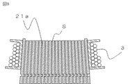
図4は、分割積層鉄心2を内周側から見た図である。
分割積層鉄心2の分割積層ティース部21の内周側の先端には、鉄心片2bのV字状の切り欠きb1が積み重なって溝Mが形成される。また、両端の鉄心片2aのティース部2atの内周側先端には切り欠きが無いので、この溝Mの両端は閉じている。隣接する鉄心片2a、2b同士の積層間の隙間Sには接着剤7が注入され、隣接する鉄心片2a、2b同士を固着している。ここで、各図では分割積層ティース部21部分のみに接着剤7が注入されているような図を示したが、もちろん分割積層バックヨーク部22や分割積層鉄心2の積層間全体に接着剤7が注入されてもよい。
FIG. 4 is a view of the divided
A groove M is formed by stacking the V-shaped notches b1 of the core piece 2b at the tip on the inner peripheral side of the divided
次に、分割積層鉄心2の製造方法を説明する。
図5は、分割積層鉄心2の積層間に接着剤を注入する際の加圧工程、接着剤注入工程を示す図である。
図6は、接着剤注入工程の後に分割積層鉄心2の形状を矯正する調整工程を示す図である。
Next, the manufacturing method of the division | segmentation laminated | stacked
FIG. 5 is a diagram showing a pressurizing process and an adhesive injecting process when injecting an adhesive between the laminated
FIG. 6 is a diagram illustrating an adjustment process for correcting the shape of the divided
鉄心片2a、2bを電磁鋼板から打ち抜いた後、両端に鉄心片2aを、中間層に所定の枚数の鉄心片2bを積層し、積層の両端から積層方向に加圧することによりカシメ部6を強固に嵌合させて隣接する鉄心片2a、2b同士を積層方向に連結する(積層工程)。次に、インシュレータ5を分割積層鉄心2に装着した後、図5(b)の矢印Iに示す方向に、分割積層バックヨーク部22を積層の両端部側から挟み込むように加圧することで、分割積層ティース部21の特に先端側で積層間に隙間Sを発生させる(加圧工程)。
After punching the core pieces 2a and 2b from the magnetic steel sheet, the core pieces 2a are laminated at both ends, a predetermined number of the core pieces 2b are laminated on the intermediate layer, and the crimping
分割積層ティース部21の先端を上向きにして固定し、溝Mに沿って接着剤7をディスペンサ8により流し入れることにより(接着剤注入工程)、各隙間Sから接着剤7が積層間に染み込む。接着剤7が硬化する前に矢印I方向の加圧を止め、積層間の隙間Sを無くした状態に戻す(脱圧工程)。
By fixing the tip of the divided
さらに、接着剤7が硬化する前に、例えば図6の矢印IIに示す方向から矯正治具9により分割積層鉄心2を矯正した状態に加圧し(分割積層鉄心2の外周側と内周側を押圧することとなる)、そのまま接着剤7を硬化させることで、精度の良い分割積層鉄心2を形成しても良い(調整工程)。
Further, before the adhesive 7 is cured, for example, the divided
ここで、接着剤7は、例えばワニスなどを用いて加熱硬化させても良い。溝Mにワニスを滴下し、ワニスを溜めた状態で、加熱することで、ワニスの粘度を下げ、分割積層鉄心内に浸透させる。また、この断面V字形状の溝Mの幅、深さは、接着に必要なワニスの滴下量に合わせて調整して構成する。また、UVを照射させて硬化させるタイプの接着剤を用いても良い。 Here, the adhesive 7 may be heat-cured using, for example, a varnish. A varnish is dripped at the groove | channel M, the viscosity of a varnish is reduced by heating in the state which stored the varnish, and it osmose | permeates in a division | segmentation laminated | stacked iron core. Further, the width and depth of the groove M having a V-shaped cross section are adjusted according to the amount of varnish dripping required for bonding. Further, an adhesive that is cured by being irradiated with UV may be used.
そして、接着剤7が完全に硬化したら分割積層鉄心2にインシュレータ5装着し(絶縁工程)、コイル3を巻回する(コイル巻回工程)。インシュレータ5を用いずに、分割積層鉄心2に絶縁塗装を施しても良い。所定の個数のコイル3を巻回した分割積層鉄心2を円環状に組み立てて固定子100を得る。
When the adhesive 7 is completely cured, the
本発明の実施の形態1に係る積層鉄心、固定子、積層鉄心の製造方法、固定子の製造方法によれば、分割積層鉄心2の積層間の隙間Sに分割積層ティース部21の先端に設けた溝Mから接着剤7を注入・硬化させることで、摘下した接着剤7が、溢れることなく一旦、溝Mに溜まり、分割積層ティース部の内周側外部にはみ出さない。これにより、はみ出した接着剤7を清掃する必要がない。また、接着剤7の浸透を待たずに所定の量の接着剤7を滴下できるので、作業性が向上する。また、滴下必要量に合わせて溝Mの横幅、深さを決定することで、接着剤7の滴下量の管理がし易く、積層鉄心の生産性を向上できる。
According to the laminated iron core, the stator, the laminated iron core manufacturing method, and the stator manufacturing method according to
図7、図8は、溝の他の例を示す図である。
図4では両端が閉じている溝Mを設けた例を説明したが、浸透性の高い接着剤7を用いれば、図7(a)のよう両端が解放されている溝M2であっても良い。また、図7(b)に示すように中間層の一部の積層にも鉄心片2aを用いて、分割された溝M3を設けても良い。また、溝は軸方向の断面形状がV字形状のものに限られる訳ではなく、図8に示すように、皿状の溝M4であっても良い。
7 and 8 are diagrams showing another example of the groove.
FIG. 4 illustrates an example in which the groove M having both ends closed is provided. However, if a highly
図9は、分割積層鉄心のコイルの巻回による巻き締まりを説明する図である。
例えば、図9に示すように接着剤7をもし注入しなかった場合、コイル3を巻回したとき、分割積層鉄心の積層間の隙間Sがコイル3を巻回する時の張力により狭まる、いわゆる巻き締まりが発生する。
FIG. 9 is a diagram for explaining the tightening due to the winding of the coil of the divided laminated iron core.
For example, when the adhesive 7 is not injected as shown in FIG. 9, when the coil 3 is wound, the gap S between the laminated laminated iron cores is narrowed by the tension when the coil 3 is wound. Tightening occurs.
この時、図に示すようにコイル3を巻回した分割積層ティース部21a側の隙間Sが積層方向に狭くなり、分割積層鉄心の精度が著しく悪化する。分割積層鉄心の精度が悪化すると、回転電機の固定子を製造する際に、フレームの挿入作業性が悪化する。また、焼き嵌めする場合は、高い温度までフレームを温めて、フレームを大きくした状態でないとフレームに磁極ティースを挿入できなくなり、フレームを温める時間とエネルギーが余分に必要になる。一方、本実施の形態の構成では、分割積層鉄心の剛性が増し、接着剤7が積層間の隙間Sを埋めるので巻き締まりが発生しない。これにより、分割積層鉄心の精度が向上し、固定子100の組立作業性が良くなり、固定子100の生産性が向上する。 At this time, as shown in the drawing, the gap S on the side of the divided laminated tooth portion 21a around which the coil 3 is wound is narrowed in the laminating direction, and the accuracy of the divided laminated iron core is remarkably deteriorated. When the accuracy of the split laminated iron core is deteriorated, the workability of inserting the frame is deteriorated when the stator of the rotating electric machine is manufactured. In addition, when shrink fitting is performed, the frame is heated to a high temperature and the magnetic teeth cannot be inserted into the frame unless the frame is enlarged, and extra time and energy are required to warm the frame. On the other hand, in the configuration of the present embodiment, the rigidity of the divided laminated iron core is increased, and the adhesive 7 fills the gap S between the laminated layers, so that no winding tightening occurs. As a result, the accuracy of the split laminated iron core is improved, the assembly workability of the stator 100 is improved, and the productivity of the stator 100 is improved.
また、積層鉄心の剛性が増すことで回転電機の振動や騒音を抑制できる。また、鉄心片2a、2bのバックヨーク部2ay、2byにカシメ部6を設け、ティース部2at、2btにカシメ部を設けないことで、バックヨーク部2ay、2byを積層方向に挟み込むように加圧することで、分割積層ティース部21の特に先端側で積層間に隙間Sを発生させた状態で接着剤7を十分に注入できる。これにより、さらに分割積層鉄心の剛性が向上し、積層鉄心の精度の向上と振動騒音の抑制が可能となる。
Moreover, vibration and noise of the rotating electrical machine can be suppressed by increasing the rigidity of the laminated iron core. In addition, the back yoke portions 2ay and 2by of the iron core pieces 2a and 2b are provided with the crimping
また、例えば、ワニスなど温度上昇により粘土が低下し浸透する接着剤7を使用する場合、温度をあまり上げなくても隙間Sの隅々まで簡単に接着剤7を注入できるので接着作業性が向上し製品の生産性が向上する。 In addition, for example, when using an adhesive 7 such as a varnish that allows the clay to be lowered and penetrated, the adhesive 7 can be easily injected to every corner of the gap S without increasing the temperature so that the adhesion workability is improved. Product productivity is improved.
また、接着剤7を注入した後、分割積層鉄心2の形状を矯正して接着剤7を硬化させることができるため、金型パンチの磨耗によるカシメ部6の精度悪化や鉄心片の板厚のばらつきなどにより分割積層鉄心2の積層間に傾斜、ズレが生じても、接着剤7の注入後の矯正により分割積層鉄心の精度を改善でき、組立作業性がよくなり、固定子100の生産性が向上する。
In addition, since the adhesive 7 can be cured by correcting the shape of the split laminated
更に、分割積層ティース部21に磁路を妨げるカシメ部6が存在せず、磁気抵抗を低減でき、鉄損の低減による回転電機の効率向上が図られる。また、分割積層ティース部21の磁気飽和を抑制できるので回転電機のトルク増加等、回転電機の特性を向上することができる。
Further, the crimping
なお、カシメ部6の形状や個数はこれに限ったものではない。図10は、本発明の実施の形態1による別のカシメ部6a、6bを有する分割積層鉄心の平面図である。例えば、図に示すように分割積層バックヨーク部22にカシメ部6a、6bを2箇所設けても良い。また、カシメ部6は設けなくても良い。
Note that the shape and number of the crimping
図11(a)は、カシメ部の代わりに、分割積層バックヨーク部22の外周面に積層間を固定する溶接部24を設けた分割積層鉄心2の平面図である。
図11(b)は、図11(a)のZ−Z線における断面図である。上述の例ではカシメ部6により分割積層バックヨーク部22の積層間を連結していたが、図11に示すように溶接部24により積層間を連結しても良い。なお、固定子の構造においても、分割積層ティース部21の数や形状は、本実施の形態で説明したものに限るものではない。
FIG. 11A is a plan view of the divided
FIG.11 (b) is sectional drawing in the ZZ line | wire of Fig.11 (a). In the above-described example, the laminations of the divided laminated back
実施の形態2.
以下、本発明の実施の形態2に係る積層鉄心、固定子、積層鉄心の製造方法、固定子の製造方法を図を用いて実施の形態1と異なる部分を中心に説明する。
図12は、分割積層鉄心202の斜視図である。
図13は、分割積層鉄心202を構成する鉄心片202bの平面図である。鉄心片202bは実施の形態1における鉄心片2bに相当する。
図14は、鉄心片202bが環状に組み合わされた状態(積層鉄心の1つの積層)を示す図である。
Hereinafter, the laminated iron core, the stator, the method for producing the laminated iron core, and the method for producing the stator according to the second embodiment of the present invention will be described with reference to the drawings, focusing on the differences from the first embodiment.
FIG. 12 is a perspective view of the divided
FIG. 13 is a plan view of the iron core piece 202b constituting the divided
FIG. 14 is a diagram illustrating a state where the core pieces 202b are combined in a ring shape (one laminated core).
本実施の形態では、接着剤溜まりM5(実施の形態の溝Mに相当)の構成が実施の形態1と異なる。図14に示すように、ティース部202btの先端の円弧状部分の曲率半径R2が、積層鉄心の内周が形成する円の半径R1より小さくなるように構成することで、分割積層鉄心202の内周側先端部に積層方向に垂直な断面が円弧状の接着剤溜まりM5を設けることができ、実施の形態1と同様の効果が得られる。また、実施の形態1と同様に積層の両端の鉄心片202aには、切り欠きを設けない構成とすることで、接着剤7を溜める窪みができ、接着剤7が分割積層鉄心202の内周側、外周側及び積層方向にはみ出したり、こぼれたりすることを抑制でき、更なる作業性の向上が可能となる。
In the present embodiment, the configuration of the adhesive reservoir M5 (corresponding to the groove M in the embodiment) is different from that in the first embodiment. As shown in FIG. 14, by configuring the radius of curvature R2 of the arc-shaped portion at the tip of the tooth portion 202bt to be smaller than the radius R1 of the circle formed by the inner periphery of the laminated core, An adhesive reservoir M5 having an arc-shaped cross section perpendicular to the stacking direction can be provided at the circumferential tip, and the same effect as in the first embodiment can be obtained. Further, similarly to the first embodiment, the core pieces 202 a at both ends of the laminate are not provided with a notch, so that a recess for storing the adhesive 7 can be formed, and the adhesive 7 is formed on the inner periphery of the split laminated
実施の形態3.
以下、本発明の実施の形態3に係る積層鉄心、固定子、積層鉄心の製造方法、固定子の製造方法を図を用いて実施の形態1と異なる部分を中心に説明する。
図15(a)は、本実施の形態に係る分割積層鉄心302の平面図である。
図15(b)は、接着剤7を注入中の分割積層鉄心302のZ3−Z3線における断面図である。
図16は、穴a3に滴下した接着剤7が、積層間の隙間Sに浸透する状態を示す模式図である。
Embodiment 3 FIG.
Hereinafter, the laminated iron core, the stator, the method for producing the laminated iron core, and the method for producing the stator according to the third embodiment of the present invention will be described with reference to the drawings, focusing on the differences from the first embodiment.
FIG. 15A is a plan view of the divided
FIG. 15B is a cross-sectional view taken along the line Z3-Z3 of the split laminated
FIG. 16 is a schematic diagram showing a state where the adhesive 7 dropped into the hole a3 penetrates into the gap S between the layers.
図15(a)、(b)に示すように、分割積層鉄心302の最下層以外を構成する鉄心片302cのティース部302ctの中央付近には接着剤7注入用の穴a3を設けている。また、積層の最下層の鉄心片302dだけは、注入した接着剤7が漏れないように、穴a3は設けていない。接着剤7の注入は、図15(b)に示すように分割積層鉄心302の積層方向が鉛直方向と一致するように立てた状態で、穴a3にめがけて接着剤7を垂らし、穴a3を設けていない鉄心片302dで接着剤7を堰き止め、積層間の隙間Sに接着剤7を浸透させる。
As shown in FIGS. 15A and 15B, a hole a3 for injecting the adhesive 7 is provided in the vicinity of the center of the tooth portion 302ct of the iron core piece 302c constituting the part other than the lowermost layer of the divided
本発明の実施の形態3に係る積層鉄心、固定子、積層鉄心の製造方法、固定子の製造方法によれば、分割積層ティース部321の中心付近から分割積層鉄心全体に接着剤7を浸透させることができ、分割積層鉄心302の剛性を向上できる。また、接着剤7を穴a3に滴下するだけで接着剤7を浸透積層間の隙間Sに注入でき、分割積層鉄心302の製造時の作業性を向上できる。
According to the laminated core, the stator, the laminated core manufacturing method, and the stator manufacturing method according to Embodiment 3 of the present invention, the adhesive 7 is permeated from the vicinity of the center of the divided
なお、穴a3は接着剤7を滴下できれば、どれだけ小さくても良く、穴a3を小さく構成することで、磁路が妨げられることがなく、分割積層鉄心302の磁気特性を向上できる。また、穴の数も1つに限ったものではなく、分割積層ティース部321の長手方向に2つ以上並べて設け、ディスペンサ8の滴下ノズルを穴の数に合わせて増やしても良い。一度に複数の穴に接着剤7を滴下でき、分割積層鉄心302の生産性が更に向上する。
Note that the hole a3 may be as small as the adhesive 7 can be dropped, and by configuring the hole a3 to be small, the magnetic path is not obstructed and the magnetic characteristics of the divided
また、上述のように最下層の鉄心片302dには穴a3は設けなかったが、全ての積層に穴a3を有する鉄心片302cを用い、最下層の鉄心片の穴a3を治具などで塞いで接着剤7を滴下しても良く、このように構成すれば、分割積層鉄心302の全ての積層に同じ鉄心片302cを利用でき、分割積層鉄心302の生産性を向上できる。
Further, as described above, the hole a3 is not provided in the
実施の形態4.
以下、本発明の実施の形態4に係る積層鉄心、固定子、積層鉄心の製造方法、固定子の製造方法を図を用いて実施の形態1と異なる部分を中心に説明する。
図17は、本発明の実施の形態4に係る積層鉄心420にコイル3を巻回した固定子400の平面図である。
図18は、図17の分割積層鉄心402に、積層間を固着する接着剤を滴下する接着剤注入工程を示す図である。
実施の形態1では、ばらばらの分割積層鉄心2を組み合わせて積層鉄心20を構成する例を説明したが、本実施の形態では、複数の分割積層鉄心402が回転連結部25により回転可能に連結されている。
Hereinafter, the laminated iron core, the stator, the method for producing the laminated iron core, and the method for producing the stator according to the fourth embodiment of the present invention will be described with a focus on differences from the first embodiment with reference to the drawings.
FIG. 17 is a plan view of a
FIG. 18 is a diagram showing an adhesive injection step of dropping an adhesive for fixing the laminated layers onto the divided
In the first embodiment, the example in which the
本実施の形態で用いる分割積層鉄心402も実施の形態1の分割積層鉄心2と同様に、分割積層バックヨーク部422の積層間はカシメ部6で連結され、分割積層ティース部421の積層間の隙間に接着剤7を注入、硬化させることで、実施の形態1と同様の効果が得られる。
Similarly to the divided
本発明の実施の形態4に係る積層鉄心、固定子、積層鉄心の製造方法、固定子の製造方法によれば、各分割積層鉄心402を連結し、一体として取り扱うことができ、搬送、組立などの作業性を向上し、組立工程を自動化し易く、積層鉄心420の生産性を向上できる。また、回転連結部25により全ての分割積層鉄心402を回転可能に連結しているため、分割積層ティース部421の間を広げてコイル3を巻回することにより、高密度に生産性よくコイル3を巻回できる。
According to the laminated core, the stator, the laminated core manufacturing method, and the stator manufacturing method according to
また、分割積層ティース部421の積層間は接着剤7により固定され剛性が高いため、実施の形態1と同様にコイル3の巻回の際に積層鉄心420の精度が悪化することを防止でき、容易に生産性よく固定子400を組み立てることができる。
In addition, since the lamination between the laminated laminated teeth portions 421 is fixed by the adhesive 7 and has high rigidity, it is possible to prevent the accuracy of the
なお、図18では複数のディスペンサ8を用いて一度に接着剤7を滴下しているが、1つのディスペンサ8を用いて順に分割積層ティース部421に接着剤7を滴下しても良い。
In FIG. 18, the adhesive 7 is dropped at once using a plurality of
ここで、接着剤7が回転連結部25に流れ込んで硬化すると、後の組立工程で積層鉄心420をうまく組み立てられない。これを防止するために、カシメ部6を回転連結部25の近くに1箇所ずつ、計2箇所に設けている。このように構成することで、積層間の隙間を分割積層ティース部421側から流れてきた接着剤7がカシメ部6で堰き止められ、回転連結部25に接着剤7が進入することを抑制することができる。
Here, if the adhesive 7 flows into the
尚、本発明は、その発明の範囲内において、各実施の形態を自由に組み合わせたり、各実施の形態を適宜、変形、省略することが可能である。 It should be noted that the present invention can be freely combined with each other within the scope of the invention, and each embodiment can be appropriately modified or omitted.
100,400 固定子、2,202,302,402 分割積層鉄心、
21,21a,321,421 分割積層ティース部、
22,422 分割積層バックヨーク部、24 溶接部、25 回転連結部、
2a,2b,202a,202b,302c,302d 鉄心片、
2at,2bt,202bt,302ct ティース部、
2ay,2by バックヨーク部、3 コイル、4 フレーム、5 インシュレータ、
6,6a カシメ部、7 接着剤、8 ディスペンサ、9 矯正治具、
M,M2,M3,M4 溝、S 隙間、20,420 積層鉄心、a3 穴。
100,400 stator, 2,202,302,402 split laminated iron core,
21, 21a, 321, 421 divided laminated teeth,
22, 422 split laminated back yoke part, 24 welded part, 25 rotary connecting part,
2a, 2b, 202a, 202b, 302c, 302d core pieces,
2at, 2bt, 202bt, 302ct teeth part,
2ay, 2by Back yoke part, 3 coil, 4 frame, 5 insulator,
6, 6a Caulking part, 7 Adhesive, 8 Dispenser, 9 Straightening jig,
M, M2, M3, M4 groove, S gap, 20,420 laminated iron core, a3 hole.
Claims (4)
前記ティース部の先端に切り欠きを設けて前記鉄心片を電磁鋼板から打ち抜く鉄心片打ち抜き工程と、
前記鉄心片を積層し、分割積層ティース部の内周側の先端に軸方向に延在する溝を有する前記分割積層鉄心を構成する積層工程と、
前記バックヨーク部が積層された部分である、分割積層バックヨーク部を積層方向の両端部から積層方向に加圧する加圧工程と、
前記加圧工程を実施しながら、前記ティース部が積層された部分である分割積層ティース部の先端を上向きにして、前記分割積層ティース部の溝に対して、接着剤を滴下する、接着剤注入工程と、
前記接着剤が硬化する前に前記分割積層バックヨーク部に対する加圧を止める脱圧工程と、
前記分割積層鉄心を円環状に組み合わせて前記積層鉄心を構成する組み立て工程とを備えた積層鉄心の製造方法。 A manufacturing method of a laminated core comprising a back yoke part and a teeth part protruding from the back yoke part, and a plurality of divided laminated cores obtained by laminating iron core pieces punched from electromagnetic steel sheets, connected in an annular shape,
An iron core piece punching step in which a notch is provided at the tip of the teeth portion and the iron core piece is punched out from the electromagnetic steel sheet;
Lamination step of laminating the core pieces and configuring the split laminated core having a groove extending in the axial direction at the tip on the inner peripheral side of the divided laminated teeth portion;
A pressurizing step of pressurizing the divided laminated back yoke part in the laminating direction from both ends in the laminating direction, which is a portion where the back yoke part is laminated;
Adhesive injection in which the adhesive is dropped into the groove of the divided laminated tooth portion with the tip of the divided laminated tooth portion facing upward while performing the pressurizing step. Process,
A depressurization step of stopping the pressurization to the divided laminated back yoke portion before the adhesive is cured;
A manufacturing method of a laminated core comprising: an assembly step of configuring the laminated core by combining the divided laminated cores in an annular shape.
Priority Applications (1)
| Application Number | Priority Date | Filing Date | Title |
|---|---|---|---|
| JP2014006308A JP6066936B2 (en) | 2014-01-17 | 2014-01-17 | Laminated core manufacturing method, stator manufacturing method |
Applications Claiming Priority (1)
| Application Number | Priority Date | Filing Date | Title |
|---|---|---|---|
| JP2014006308A JP6066936B2 (en) | 2014-01-17 | 2014-01-17 | Laminated core manufacturing method, stator manufacturing method |
Publications (2)
| Publication Number | Publication Date |
|---|---|
| JP2015136228A JP2015136228A (en) | 2015-07-27 |
| JP6066936B2 true JP6066936B2 (en) | 2017-01-25 |
Family
ID=53767716
Family Applications (1)
| Application Number | Title | Priority Date | Filing Date |
|---|---|---|---|
| JP2014006308A Expired - Fee Related JP6066936B2 (en) | 2014-01-17 | 2014-01-17 | Laminated core manufacturing method, stator manufacturing method |
Country Status (1)
| Country | Link |
|---|---|
| JP (1) | JP6066936B2 (en) |
Families Citing this family (12)
| Publication number | Priority date | Publication date | Assignee | Title |
|---|---|---|---|---|
| JP2017046480A (en) * | 2015-08-27 | 2017-03-02 | 日産自動車株式会社 | Manufacturing method for rotor core and rotor core for rotary electric machine |
| WO2020129923A1 (en) | 2018-12-17 | 2020-06-25 | 日本製鉄株式会社 | Laminated core and rotary electric machine |
| EP3902104A4 (en) * | 2018-12-17 | 2022-10-05 | Nippon Steel Corporation | Laminated core and rotating electric machine |
| TWI725670B (en) | 2018-12-17 | 2021-04-21 | 日商日本製鐵股份有限公司 | Laminated iron core, its manufacturing method and rotating electric machine |
| US11710990B2 (en) * | 2018-12-17 | 2023-07-25 | Nippon Steel Corporation | Laminated core with circumferentially spaced adhesion parts on teeth |
| US11923130B2 (en) | 2018-12-17 | 2024-03-05 | Nippon Steel Corporation | Laminated core and electric motor |
| EP3902111A4 (en) | 2018-12-17 | 2022-10-05 | Nippon Steel Corporation | Laminated core and rotating electric machine |
| KR102583082B1 (en) | 2018-12-17 | 2023-09-27 | 닛폰세이테츠 가부시키가이샤 | Adhesive laminated core, its manufacturing method and rotary electric machine |
| KR102572555B1 (en) | 2018-12-17 | 2023-08-30 | 닛폰세이테츠 가부시키가이샤 | Laminated cores and rotating electrical appliances |
| JP7418216B2 (en) * | 2020-01-06 | 2024-01-19 | 三菱電機株式会社 | A stator core for a rotating electrical machine, a stator for a rotating electrical machine, a rotating electrical machine, a method for manufacturing a stator core for a rotating electrical machine, and a method for producing a rotating electrical machine |
| JP7435154B2 (en) * | 2020-03-27 | 2024-02-21 | ニデック株式会社 | Plate laminates, laminated cores and motors |
| JP2021191039A (en) * | 2020-05-26 | 2021-12-13 | 日本電産株式会社 | Manufacturing method of laminated iron core |
Family Cites Families (8)
| Publication number | Priority date | Publication date | Assignee | Title |
|---|---|---|---|---|
| JPS5385303A (en) * | 1977-01-05 | 1978-07-27 | Hitachi Ltd | Laminated iron core of electric machine and apparatus |
| US6301773B1 (en) * | 1997-11-10 | 2001-10-16 | General Electric Company | Method of manufacturing a motor core |
| JP4747423B2 (en) * | 2001-03-02 | 2011-08-17 | パナソニック株式会社 | Electric motor |
| JP4121008B2 (en) * | 2001-07-03 | 2008-07-16 | 三菱電機株式会社 | Stator and manufacturing method thereof, and stator core member manufacturing apparatus |
| JP2006246621A (en) * | 2005-03-03 | 2006-09-14 | Asmo Co Ltd | Core for rotary electric machine, its manufacturing method, and embedded magnet motor |
| JP2006288114A (en) * | 2005-04-01 | 2006-10-19 | Mitsui High Tec Inc | Laminated core and manufacturing method of laminated core |
| JP2012120299A (en) * | 2010-11-30 | 2012-06-21 | Mitsubishi Electric Corp | Stator core, rotary electric machine, and manufacturing method of stator core |
| JP5296856B2 (en) * | 2011-11-02 | 2013-09-25 | アスモ株式会社 | Stator manufacturing method |
-
2014
- 2014-01-17 JP JP2014006308A patent/JP6066936B2/en not_active Expired - Fee Related
Also Published As
| Publication number | Publication date |
|---|---|
| JP2015136228A (en) | 2015-07-27 |
Similar Documents
| Publication | Publication Date | Title |
|---|---|---|
| JP6066936B2 (en) | Laminated core manufacturing method, stator manufacturing method | |
| KR101345029B1 (en) | Method of manufacturing molded stator of dynamo electric machine | |
| JP6633212B2 (en) | Laminated core, manufacturing method of laminated core, and armature using laminated core | |
| JP6802905B2 (en) | Manufacturing method of rotor of rotating electric machine | |
| JP2012120299A (en) | Stator core, rotary electric machine, and manufacturing method of stator core | |
| US8125113B2 (en) | Slot wedges for electrical machines | |
| JP2002034187A (en) | Magnet embedded rotor | |
| WO2017154576A1 (en) | Stator for rotating electric motor, and rotating electric motor | |
| JP2012029494A (en) | Electric motor and manufacturing method of the same | |
| JP2009240111A (en) | Rotor core manufacturing method and motor having rotor core | |
| JP2017163703A (en) | Laminated iron core manufacturing method | |
| JP2017163757A (en) | Rotor and method of manufacturing the rotor | |
| JP2007151360A (en) | Method of manufacturing laminate | |
| CN110268608B (en) | Method for manufacturing component for rotating electrical machine | |
| WO2020054057A1 (en) | Rotary electric machine | |
| JP2020089059A (en) | Armature molded structure | |
| CN112737166B (en) | Rotary electric machine and method for manufacturing rotary electric machine | |
| JP2006197779A (en) | Stator of rotary electric machine, and manufacturing method and device thereof | |
| WO2017187522A1 (en) | Stator, electric motor, stator manufacturing method, and electric motor manufacturing method | |
| JP6837128B2 (en) | Manufacturing method of stator of rotary electric machine | |
| JP6685434B2 (en) | Rotating electric machine stator and method of manufacturing rotating electric machine stator | |
| JP2019161769A (en) | Stator and rotary electric machine including the same | |
| JP6805712B2 (en) | How to manufacture the rotor | |
| CN109196758B (en) | Rotating electrical machine | |
| JP2018117440A (en) | Rotary electric machine |
Legal Events
| Date | Code | Title | Description |
|---|---|---|---|
| A621 | Written request for application examination |
Free format text: JAPANESE INTERMEDIATE CODE: A621 Effective date: 20150917 |
|
| A977 | Report on retrieval |
Free format text: JAPANESE INTERMEDIATE CODE: A971007 Effective date: 20160602 |
|
| A131 | Notification of reasons for refusal |
Free format text: JAPANESE INTERMEDIATE CODE: A131 Effective date: 20160614 |
|
| A521 | Written amendment |
Free format text: JAPANESE INTERMEDIATE CODE: A523 Effective date: 20160712 |
|
| TRDD | Decision of grant or rejection written | ||
| A01 | Written decision to grant a patent or to grant a registration (utility model) |
Free format text: JAPANESE INTERMEDIATE CODE: A01 Effective date: 20161122 |
|
| A61 | First payment of annual fees (during grant procedure) |
Free format text: JAPANESE INTERMEDIATE CODE: A61 Effective date: 20161220 |
|
| R150 | Certificate of patent or registration of utility model |
Ref document number: 6066936 Country of ref document: JP Free format text: JAPANESE INTERMEDIATE CODE: R150 |
|
| LAPS | Cancellation because of no payment of annual fees |