JP6543608B2 - Method of manufacturing laminated core and apparatus for manufacturing laminated core - Google Patents
Method of manufacturing laminated core and apparatus for manufacturing laminated core Download PDFInfo
- Publication number
- JP6543608B2 JP6543608B2 JP2016249398A JP2016249398A JP6543608B2 JP 6543608 B2 JP6543608 B2 JP 6543608B2 JP 2016249398 A JP2016249398 A JP 2016249398A JP 2016249398 A JP2016249398 A JP 2016249398A JP 6543608 B2 JP6543608 B2 JP 6543608B2
- Authority
- JP
- Japan
- Prior art keywords
- core members
- iron core
- adhesive
- temporary
- laminate
- Prior art date
- Legal status (The legal status is an assumption and is not a legal conclusion. Google has not performed a legal analysis and makes no representation as to the accuracy of the status listed.)
- Active
Links
- 238000004519 manufacturing process Methods 0.000 title claims description 57
- 239000000853 adhesive Substances 0.000 claims description 133
- 230000001070 adhesive effect Effects 0.000 claims description 126
- 238000004080 punching Methods 0.000 claims description 123
- 238000012545 processing Methods 0.000 claims description 110
- 238000000034 method Methods 0.000 claims description 89
- XEEYBQQBJWHFJM-UHFFFAOYSA-N Iron Chemical group [Fe] XEEYBQQBJWHFJM-UHFFFAOYSA-N 0.000 claims description 83
- 230000007246 mechanism Effects 0.000 claims description 73
- 230000008569 process Effects 0.000 claims description 60
- 238000010030 laminating Methods 0.000 claims description 55
- 238000003780 insertion Methods 0.000 claims description 35
- 230000037431 insertion Effects 0.000 claims description 35
- 238000000137 annealing Methods 0.000 claims description 33
- 238000003475 lamination Methods 0.000 claims description 32
- 238000005096 rolling process Methods 0.000 claims description 30
- 239000002184 metal Substances 0.000 claims description 26
- 229910052751 metal Inorganic materials 0.000 claims description 26
- 238000005259 measurement Methods 0.000 claims description 20
- 239000003795 chemical substances by application Substances 0.000 claims description 15
- 230000000149 penetrating effect Effects 0.000 claims description 4
- 238000000926 separation method Methods 0.000 claims description 4
- 229910000831 Steel Inorganic materials 0.000 description 36
- 239000010959 steel Substances 0.000 description 36
- 230000006870 function Effects 0.000 description 16
- 238000005452 bending Methods 0.000 description 9
- 230000007547 defect Effects 0.000 description 9
- 239000000463 material Substances 0.000 description 8
- 230000000694 effects Effects 0.000 description 7
- 238000003384 imaging method Methods 0.000 description 7
- 230000002093 peripheral effect Effects 0.000 description 6
- 238000003860 storage Methods 0.000 description 6
- 239000002671 adjuvant Substances 0.000 description 5
- 238000005520 cutting process Methods 0.000 description 5
- 239000010410 layer Substances 0.000 description 5
- 239000007788 liquid Substances 0.000 description 5
- NJPPVKZQTLUDBO-UHFFFAOYSA-N novaluron Chemical compound C1=C(Cl)C(OC(F)(F)C(OC(F)(F)F)F)=CC=C1NC(=O)NC(=O)C1=C(F)C=CC=C1F NJPPVKZQTLUDBO-UHFFFAOYSA-N 0.000 description 5
- 238000003466 welding Methods 0.000 description 5
- 230000006872 improvement Effects 0.000 description 4
- 230000032258 transport Effects 0.000 description 4
- 239000012752 auxiliary agent Substances 0.000 description 3
- 238000013461 design Methods 0.000 description 3
- 238000007599 discharging Methods 0.000 description 3
- 238000010438 heat treatment Methods 0.000 description 3
- CSCPPACGZOOCGX-UHFFFAOYSA-N Acetone Chemical compound CC(C)=O CSCPPACGZOOCGX-UHFFFAOYSA-N 0.000 description 2
- 230000007423 decrease Effects 0.000 description 2
- 238000010586 diagram Methods 0.000 description 2
- 238000007689 inspection Methods 0.000 description 2
- 239000000047 product Substances 0.000 description 2
- 230000009467 reduction Effects 0.000 description 2
- 239000000126 substance Substances 0.000 description 2
- 229920001187 thermosetting polymer Polymers 0.000 description 2
- 238000011144 upstream manufacturing Methods 0.000 description 2
- 238000004804 winding Methods 0.000 description 2
- 230000005856 abnormality Effects 0.000 description 1
- NIXOWILDQLNWCW-UHFFFAOYSA-N acrylic acid group Chemical group C(C=C)(=O)O NIXOWILDQLNWCW-UHFFFAOYSA-N 0.000 description 1
- 239000012790 adhesive layer Substances 0.000 description 1
- 238000013459 approach Methods 0.000 description 1
- 239000011248 coating agent Substances 0.000 description 1
- 238000000576 coating method Methods 0.000 description 1
- 230000006866 deterioration Effects 0.000 description 1
- 238000001035 drying Methods 0.000 description 1
- 229920006332 epoxy adhesive Polymers 0.000 description 1
- 239000012467 final product Substances 0.000 description 1
- 239000003999 initiator Substances 0.000 description 1
- 238000009434 installation Methods 0.000 description 1
- 238000012423 maintenance Methods 0.000 description 1
- 229910021645 metal ion Inorganic materials 0.000 description 1
- 238000002156 mixing Methods 0.000 description 1
- 238000012986 modification Methods 0.000 description 1
- 230000004048 modification Effects 0.000 description 1
- 230000003287 optical effect Effects 0.000 description 1
- 238000003825 pressing Methods 0.000 description 1
- 230000004044 response Effects 0.000 description 1
- 239000004065 semiconductor Substances 0.000 description 1
- 239000002904 solvent Substances 0.000 description 1
- 238000003892 spreading Methods 0.000 description 1
- 230000007480 spreading Effects 0.000 description 1
Images


Classifications
-
- H—ELECTRICITY
- H02—GENERATION; CONVERSION OR DISTRIBUTION OF ELECTRIC POWER
- H02K—DYNAMO-ELECTRIC MACHINES
- H02K15/00—Methods or apparatus specially adapted for manufacturing, assembling, maintaining or repairing of dynamo-electric machines
- H02K15/02—Methods or apparatus specially adapted for manufacturing, assembling, maintaining or repairing of dynamo-electric machines of stator or rotor bodies
- H02K15/024—Methods or apparatus specially adapted for manufacturing, assembling, maintaining or repairing of dynamo-electric machines of stator or rotor bodies with slots
-
- B—PERFORMING OPERATIONS; TRANSPORTING
- B21—MECHANICAL METAL-WORKING WITHOUT ESSENTIALLY REMOVING MATERIAL; PUNCHING METAL
- B21D—WORKING OR PROCESSING OF SHEET METAL OR METAL TUBES, RODS OR PROFILES WITHOUT ESSENTIALLY REMOVING MATERIAL; PUNCHING METAL
- B21D28/00—Shaping by press-cutting; Perforating
- B21D28/02—Punching blanks or articles with or without obtaining scrap; Notching
-
- B—PERFORMING OPERATIONS; TRANSPORTING
- B21—MECHANICAL METAL-WORKING WITHOUT ESSENTIALLY REMOVING MATERIAL; PUNCHING METAL
- B21D—WORKING OR PROCESSING OF SHEET METAL OR METAL TUBES, RODS OR PROFILES WITHOUT ESSENTIALLY REMOVING MATERIAL; PUNCHING METAL
- B21D39/00—Application of procedures in order to connect objects or parts, e.g. coating with sheet metal otherwise than by plating; Tube expanders
- B21D39/03—Application of procedures in order to connect objects or parts, e.g. coating with sheet metal otherwise than by plating; Tube expanders of sheet metal otherwise than by folding
-
- H—ELECTRICITY
- H01—ELECTRIC ELEMENTS
- H01F—MAGNETS; INDUCTANCES; TRANSFORMERS; SELECTION OF MATERIALS FOR THEIR MAGNETIC PROPERTIES
- H01F41/00—Apparatus or processes specially adapted for manufacturing or assembling magnets, inductances or transformers; Apparatus or processes specially adapted for manufacturing materials characterised by their magnetic properties
- H01F41/02—Apparatus or processes specially adapted for manufacturing or assembling magnets, inductances or transformers; Apparatus or processes specially adapted for manufacturing materials characterised by their magnetic properties for manufacturing cores, coils, or magnets
-
- H—ELECTRICITY
- H02—GENERATION; CONVERSION OR DISTRIBUTION OF ELECTRIC POWER
- H02K—DYNAMO-ELECTRIC MACHINES
- H02K1/00—Details of the magnetic circuit
- H02K1/06—Details of the magnetic circuit characterised by the shape, form or construction
- H02K1/12—Stationary parts of the magnetic circuit
- H02K1/16—Stator cores with slots for windings
-
- H—ELECTRICITY
- H02—GENERATION; CONVERSION OR DISTRIBUTION OF ELECTRIC POWER
- H02K—DYNAMO-ELECTRIC MACHINES
- H02K15/00—Methods or apparatus specially adapted for manufacturing, assembling, maintaining or repairing of dynamo-electric machines
- H02K15/02—Methods or apparatus specially adapted for manufacturing, assembling, maintaining or repairing of dynamo-electric machines of stator or rotor bodies
Landscapes
- Engineering & Computer Science (AREA)
- Power Engineering (AREA)
- Manufacturing & Machinery (AREA)
- Mechanical Engineering (AREA)
- Manufacture Of Motors, Generators (AREA)
- Manufacturing Cores, Coils, And Magnets (AREA)
- Iron Core Of Rotating Electric Machines (AREA)
Description
本開示は、積層鉄心の製造方法及び積層鉄心の製造装置に関する。 The present disclosure relates to a method of manufacturing a laminated core and an apparatus for manufacturing the laminated core.
特許文献1は、積層鉄心の製造方法を開示している。当該方法では、コイル状に巻回された帯状の金属板(被加工板)であるコイル材をアンコイラーから間欠的に送り出しながら、当該金属板の片面に接着剤を塗布することと、当該金属板をパンチで所定形状に打ち抜いて一の打抜部材を形成することと、当該一の打抜部材を既に打ち抜かれた他の打抜部材に対して接着剤により接着させながら積層することとが、同じ金型内で行われる。
ところで、パンチの摩耗抑制、打抜部材の打抜性向上等を目的として、コイル材にはプレス加工油(スタンピングオイルともいう。以下では単に「オイル」と称する。)が塗布されていることが一般的である。オイルが存在したままの状態で金属板に接着剤を塗布し、打抜部材同士を接着しようとすると、接着剤の接着性能に影響が生ずる。そこで、特許文献1は、オイルに硬化促進剤を添加し、オイルを除去することなく打抜部材同士を接着剤で接着することを開示している。これにより、オイルの除去処理が不要となるので、積層鉄心の生産性が高まる。
By the way, in order to suppress the wear of the punch and improve the punchability of the punching member, the coil material is coated with a press working oil (also referred to as a stamping oil, hereinafter simply referred to as "oil"). It is common. If an adhesive is applied to a metal plate in the presence of oil to try to bond the punching members, the adhesive performance of the adhesive is affected. Therefore,
しかしながら、通常、金属板を打ち抜く処理よりも金属板に接着剤を供給する処理の方が遅いため、金属板に接着剤を供給する機構が金型内に存在していると、接着剤の塗布処理がボトルネックとなり積層鉄心の製造効率(スループット)が低下しうる。しかも、金属板に接着剤を供給する機構が金型内に存在していると、金型自体が大型化し、積層鉄心の製造装置のコスト増に繋がりうる。さらに、金型の異常発生時には、金型内で接着剤が硬化して積層鉄心が金型内に詰まってしまい、金型を上下動させるためのプレスから金型を分解して積層鉄心を取り出すといったメンテナンスをしなければならない場合も生じうる。 However, since the process of supplying the adhesive to the metal plate is usually slower than the process of punching the metal plate, if the mechanism for supplying the adhesive to the metal plate is present in the mold, the application of the adhesive is The processing becomes a bottleneck and the manufacturing efficiency (throughput) of the laminated core may be reduced. In addition, if the mechanism for supplying the adhesive to the metal plate is present in the mold, the mold itself becomes large, which may lead to an increase in the cost of the laminated core manufacturing apparatus. Furthermore, when a mold abnormality occurs, the adhesive hardens in the mold and the laminated core is clogged in the mold, and the mold is disassembled from the press for moving the mold up and down and the laminated core is taken out It may also occur when it is necessary to perform such maintenance.
そこで、本開示は、低コストで且つ効率的に積層鉄心を製造することが可能な積層鉄心の製造方法及び積層鉄心の製造装置を説明する。 Thus, the present disclosure describes a method of manufacturing a laminated core and an apparatus for manufacturing a laminated core that can efficiently manufacture a laminated core at low cost.
本開示の一つの観点に係る積層鉄心の製造方法は、金型内において、金属板を所定形状に沿って打ち抜いて、一つの打抜部材又は複数の打抜部材が互いに接合されたブロック体である鉄心部材を形成すると共に、複数の鉄心部材を積層して積層体を形成する仮積層工程と、積層体から鉄心部材を一つずつ取り出して、隣り合う鉄心部材同士の間に接着剤が位置するように個々の鉄心部材に接着剤を供給しつつ複数の鉄心部材を積層する本積層工程とを含む。 In a method of manufacturing a laminated core according to one aspect of the present disclosure, a metal plate is punched out along a predetermined shape in a mold, and a punching member or a block body in which a plurality of punching members are joined to each other A temporary laminating step of forming a laminated body by forming a certain iron core member and laminating a plurality of iron core members, taking out the iron core members one by one from the laminated body, and positioning the adhesive between the adjacent iron core members And laminating the plurality of core members while supplying the adhesive to the individual core members.
本開示の他の観点に係る積層鉄心の製造装置は、金属板を所定形状に沿って打ち抜いて、一つの打抜部材又は複数の打抜部材が互いに接合されたブロック体である鉄心部材を形成すると共に、複数の鉄心部材を積層して積層体を形成するように構成された金型と、鉄心部材を一つずつ保持可能に構成された保持機構と、鉄心部材に接着剤を供給可能に構成された供給機構と、制御部とを備える。制御部は、金型を制御して積層体を形成する仮積層処理と、保持機構及び供給機構を制御して、積層体から保持機構により鉄心部材を一つずつ保持しつつ取り出して、隣り合う鉄心部材同士の間に接着剤が位置するように供給機構により個々の鉄心部材に接着剤を供給しつつ、保持機構により複数の鉄心部材を積層する本積層処理とを実行する。 A laminated core manufacturing apparatus according to another aspect of the present disclosure punches a metal plate along a predetermined shape to form an iron core member which is a block body in which one punching member or a plurality of punching members are joined to each other. And a plurality of iron core members are laminated to form a laminated body, a holding mechanism configured to be able to hold the iron core members one by one, and an adhesive can be supplied to the iron core members It comprises a configured feeding mechanism and a control unit. The control unit controls the temporary lamination process of forming the laminate by controlling the mold, and the holding mechanism and the feeding mechanism, and takes out the core members one by one from the laminate while holding them by the holding mechanism and adjacent to each other. While the adhesive is supplied to the individual iron core members by the supply mechanism so that the adhesive is positioned between the iron core members, the main laminating process of laminating the plurality of iron core members by the holding mechanism is performed.
本開示に係る積層鉄心の製造方法及び積層鉄心の製造装置によれば、低コストで且つ効率的に積層鉄心を製造することが可能となる。 According to the method and apparatus for manufacturing a laminated core according to the present disclosure, it is possible to efficiently manufacture the laminated core at low cost.
以下に説明される本開示に係る実施形態は本発明を説明するための例示であるので、本発明は以下の内容に限定されるべきではない。 The embodiments according to the present disclosure described below are exemplifications for describing the present invention, and therefore the present invention should not be limited to the following contents.
≪実施形態の概要≫
[1]本実施形態の一つの例に係る積層鉄心の製造方法は、金型内において、金属板を所定形状に沿って打ち抜いて、一つの打抜部材又は複数の打抜部材が互いに接合されたブロック体である鉄心部材を形成すると共に、複数の鉄心部材を積層して積層体を形成する仮積層工程と、積層体から鉄心部材を一つずつ取り出して、隣り合う鉄心部材同士の間に接着剤が位置するように個々の鉄心部材に接着剤を供給しつつ複数の鉄心部材を積層する本積層工程とを含む。
<< Summary of Embodiment >>
[1] In a method of manufacturing a laminated core according to an example of the present embodiment, a metal plate is punched along a predetermined shape in a mold, and one punched member or a plurality of punched members are joined to each other Forming an iron core member as a block body and laminating a plurality of iron core members to form a laminated body, taking out the iron core members one by one from the laminated body, and between adjacent iron core members And laminating the plurality of core members while supplying the adhesive to the individual core members so that the adhesive is positioned.
本実施形態の一つの例に係る積層鉄心の製造方法では、金型において積層体を形成した後に、各鉄心部材の接着及び積層とが金型外において行われる。そのため、接着剤を供給する機構を、金型内に設ける必要がない。従って、金型を小型化することが可能となる。また、本実施形態の一つの例に係る積層鉄心の製造方法では、本積層工程において、隣り合う鉄心部材同士が接着剤で接着されることにより積層鉄心が得られる。そのため、鉄心部材同士がカシメ、溶接等で締結されている場合と比較して、磁気特性の低下が生じ難い。従って、このような積層鉄心を用いてモータを製造することにより、モータ特性の向上を図ることが可能となる。 In the method of manufacturing a laminated core according to one example of the present embodiment, adhesion and lamination of each core member are performed outside the mold after forming the laminated body in the mold. Therefore, there is no need to provide a mechanism for supplying the adhesive in the mold. Therefore, the mold can be miniaturized. Moreover, in the method of manufacturing a laminated core according to one example of the present embodiment, in the present lamination step, adjacent core members are adhered to each other by an adhesive to obtain a laminated core. Therefore, compared with the case where iron core members are fastened by caulking, welding or the like, the deterioration of the magnetic characteristics hardly occurs. Therefore, by manufacturing a motor using such a laminated core, it is possible to improve motor characteristics.
[2]上記第1項に記載の方法は、仮積層工程の後で且つ本積層工程の前に、金型から取り出された積層体に付着しているオイルを除去するオイル除去工程をさらに含んでいてもよい。
[2] The method according to the
ところで、通常、オイルの除去処理及び接着剤の供給処理は、金型において金属板を打ち抜いて鉄心部材を形成する処理よりも遅い。しかしながら、本実施形態の一つの例に係る積層鉄心の製造方法では、オイルを除去する機構及び接着剤を供給する機構が金型外にある。そのため、金型と独立してこれらの機構を複数設けることで、金型において鉄心部材の形成処理を高速に行いつつ、全体としてのスループットを向上させることができる。加えて、これらの機構は一般に金型よりも安価であるため、複数の金型により全体としてのスループットを向上させようとする場合と比較して、低コスト化が図られる。以上より、本実施形態の一つの例に係る積層鉄心の製造方法によれば、低コストで且つ効率的に積層鉄心を製造することが可能となる。 By the way, the oil removal process and the adhesive supply process are usually slower than the process of punching a metal plate in a mold to form an iron core member. However, in the method of manufacturing a laminated core according to one example of the present embodiment, the mechanism for removing oil and the mechanism for supplying the adhesive are outside the mold. Therefore, by providing a plurality of these mechanisms independently of the mold, it is possible to improve the overall throughput while performing the process of forming the core member at high speed in the mold. In addition, since these mechanisms are generally less expensive than molds, cost reduction can be achieved as compared to the case where the overall throughput is to be improved by a plurality of molds. As mentioned above, according to the manufacturing method of the laminated iron core concerning one example of this embodiment, it becomes possible to manufacture a laminated iron core at low cost and efficiently.
本実施形態の一つの例に係る積層鉄心の製造方法では、オイル除去工程において、金型から取り出された積層体からオイルを除去している。そのため、オイルの表面張力によって鉄心部材がくっつき合うことが抑制される。従って、後続の本積層工程において積層体から鉄心部材を一つずつ取り出しやすくなる。また、積層体全体からオイルを除去しているので、一つ一つの鉄心部材からオイルを除去する場合と比較して、オイルの除去を効率的に行える。さらに、積層体からオイルが除去されているので、接着剤の接着性能に影響が生じ難くなる。 In the method of manufacturing a laminated core according to an example of the present embodiment, the oil is removed from the laminate taken out of the mold in the oil removing step. Therefore, the surface tension of the oil prevents the core members from sticking to each other. Therefore, it becomes easy to take out the core members one by one from the laminate in the subsequent main laminating step. Further, since the oil is removed from the entire laminate, the oil can be removed more efficiently than in the case where the oil is removed from each core member. Furthermore, since the oil is removed from the laminate, the adhesive performance of the adhesive is less likely to be affected.
[3]上記第2項に記載の方法において、オイル除去工程では、積層体を焼鈍することにより積層体に付着しているオイルを除去してもよい。金型において金属板を打ち抜いて鉄心部材を形成すると、鉄心部材の周縁部が金属板から打ち抜かれる過程で鉄心部材には歪みが生ずる。歪みを有する鉄心部材を積層して得られた積層鉄心を用いてモータが製造されると、モータの特性に影響が生じうる。しかしながら、上記のように積層体を焼鈍することにより、積層体を構成している各鉄心部材の歪みが緩和される。そのため、オイルの除去と、鉄心部材の歪みの緩和とが同時に行えるため、積層鉄心を効率的に製造することが可能となる。これに対し、特許文献1に記載の方法では、接着剤が塗布された後の金属板を打ち抜いて、他の鉄心部材に対して接着剤により接着させながら積層している。そのため、得られた積層体を焼鈍しようとすると、接着剤も高温(例えば、750℃〜800℃程度)に長時間(例えば、1時間程度)曝されてしまう。焼鈍の温度に耐えうる耐熱性を有する接着剤は、本願の出願時において存在していないか、入手することが極めて困難である。従って、特許文献1に記載の方法では、鉄心部材に対して焼鈍処理することができず、鉄心部材の歪みを緩和することができないので、モータ特性の低下が懸念される。
[3] In the method according to Item 2, in the oil removing step, the oil adhering to the laminate may be removed by annealing the laminate. When a metal sheet is punched out in a mold to form an iron core member, distortion occurs in the iron core member in the process of punching out the peripheral portion of the iron core member from the metal sheet. If a motor is manufactured using a laminated core obtained by laminating core members having distortion, the characteristics of the motor may be affected. However, by annealing the laminate as described above, distortion of each core member constituting the laminate is alleviated. Therefore, since removal of oil and relaxation of distortion of an iron core member can be performed simultaneously, it becomes possible to manufacture a laminated iron core efficiently. On the other hand, in the method described in
[4]上記第2項又は第3項に記載の方法において、本積層工程では、オイル除去工程でオイルが除去された積層体から鉄心部材を一つずつ取り出して個々の鉄心部材の厚さを測定することと、鉄心部材の厚さの測定結果に基づいて個々の鉄心部材の転積の要否を判断することと、転積の要否の判断結果に基づいて、隣り合う鉄心部材同士の間に接着剤が位置するように個々の鉄心部材に接着剤を供給しつつ複数の鉄心部材を積層することとを行ってもよい。この場合、一つずつの鉄心部材において転積の要否が判断される。そのため、転積の自由度が高まるので、最終的な積層鉄心の寸法精度を向上させることが可能となる。
[4] In the method according to the
[5]上記第1項〜第4項のいずれか一項に記載の方法において、仮積層工程では、金型内において、金属板を所定形状に沿って打ち抜いて仮カシメが設けられた複数の鉄心部材を形成すると共に、複数の当該鉄心部材を仮カシメによって互いに締結しつつ積層することにより積層体を形成し、当該方法は、仮積層工程の後で且つ本積層工程の前に、積層体から仮カシメを除去して鉄心部材同士を分離する分離工程をさらに含んでもよい。この場合、本積層処理までは複数の鉄心部材を仮カシメにより積層体として一体的に取り扱える一方で、最終的な積層鉄心には仮カシメが存在せず鉄心部材同士が接着剤によって接合されている。そのため、積層鉄心の製造過程における取り扱いの容易性の向上と、モータ特性の向上との両立を図ることが可能となる。
[5] In the method according to any one of the
[6]上記第1項〜第5項のいずれか一項に記載の方法において、複数の鉄心部材にはそれぞれ、厚さ方向において貫通する複数の貫通孔が設けられており、本積層工程では、複数の貫通孔のうちいずれか二つに対応する形状の挿通ピンを備える治具に対して、複数の貫通孔のうち挿通ピンに対応する貫通孔を当該挿通ピンに挿通させつつ複数の鉄心部材を順次積層させてもよい。この場合、鉄心部材の積層と同時に、鉄心部材が所定位置に位置決めされる。そのため、鉄心部材の積層時において鉄心部材の面内でずれが生じているか否かを、鉄心部材の積層後に別途検査する必要がなくなる。従って、積層鉄心をより効率的に製造することが可能となる。
[6] In the method according to any one of
[7]本実施形態の他の例に係る積層鉄心の製造装置は、金属板を所定形状に沿って打ち抜いて、一つの打抜部材又は複数の打抜部材が互いに接合されたブロック体である鉄心部材を形成すると共に、複数の鉄心部材を積層して積層体を形成するように構成された金型と、鉄心部材を一つずつ保持可能に構成された保持機構と、鉄心部材に接着剤を供給可能に構成された供給機構と、制御部とを備える。制御部は、金型を制御して積層体を形成する仮積層処理と、保持機構及び供給機構を制御して、積層体から保持機構により鉄心部材を一つずつ保持しつつ取り出して、隣り合う鉄心部材同士の間に接着剤が位置するように供給機構により個々の鉄心部材に接着剤を供給しつつ、保持機構により複数の鉄心部材を積層する本積層処理とを実行する。本実施形態の他の例に係る積層鉄心の製造装置は、上記第1項に係る方法と同様の作用効果を奏する。 [7] A laminated iron core manufacturing apparatus according to another example of the present embodiment is a block body in which a single punching member or a plurality of punching members are joined to each other by punching a metal plate along a predetermined shape. A mold configured to form an iron core member and laminating a plurality of iron core members to form a laminate, a holding mechanism configured to be able to hold the iron core members one by one, and an adhesive to the iron core members And a control unit. The control unit controls the temporary lamination process of forming the laminate by controlling the mold, and the holding mechanism and the feeding mechanism, and takes out the core members one by one from the laminate while holding them by the holding mechanism and adjacent to each other. While the adhesive is supplied to the individual iron core members by the supply mechanism so that the adhesive is positioned between the iron core members, the main laminating process of laminating the plurality of iron core members by the holding mechanism is performed. The laminated iron core manufacturing apparatus according to another example of the present embodiment exhibits the same function and effect as the method according to the first aspect.
[8]上記第7項に記載の装置は、積層体に付着しているオイルを除去するように構成されたオイル除去機構をさらに備え、制御部は、仮積層処理の後で且つ本積層処理の前に、オイル除去機構を制御して、金型から取り出された積層体に付着しているオイルを除去するオイル除去処理をさらに実行してもよい。この場合、上記第2項と同様の作用効果が得られる。 [8] The apparatus according to the above item 7 further includes an oil removing mechanism configured to remove oil adhering to the laminate, and the control unit is configured to perform after the temporary laminating process and the main laminating process. Before this, the oil removal mechanism may be controlled to further carry out an oil removal process to remove oil adhering to the laminate removed from the mold. In this case, the same effect as that of the second term can be obtained.
[9]上記第8項に記載の装置において、オイル除去機構は積層体を焼鈍する焼鈍炉であってもよい。この場合、上記第3項と同様の作用効果が得られる。 [9] In the apparatus according to the above item 8, the oil removing mechanism may be an annealing furnace for annealing the laminate. In this case, the same effect as that of the third term is obtained.
[10]上記第8項又は第9項に記載の装置は、鉄心部材の厚さを測定可能に構成された測定機構をさらに備え、制御部は、本積層処理において、保持機構及び測定機構を制御して、仮積層処理でオイルが除去された積層体から保持機構により鉄心部材を一つずつ取り出して個々の鉄心部材を測定することと、測定機構による鉄心部材の厚さの測定結果に基づいて、個々の鉄心部材の転積の要否を判断することと、転積の要否の判断結果に基づいて保持機構及び供給機構を制御して、隣り合う鉄心部材同士の間に接着剤が位置するように供給機構により個々の鉄心部材に接着剤を供給しつつ、保持機構により複数の鉄心部材を積層することとを実行してもよい。この場合、上記第4項と同様の作用効果が得られる。 [10] The apparatus according to the above item 8 or 9 further includes a measurement mechanism configured to measure the thickness of the core member, and the control unit performs the holding mechanism and the measurement mechanism in the stacking process. The core members are taken out one by one from the laminated body from which oil has been removed by temporary lamination processing by the holding mechanism, and each individual iron core member is measured, and based on the measurement results of the thickness of the iron core members by the measuring mechanism. Between the adjacent iron core members by controlling the holding mechanism and the feeding mechanism based on the judgment as to whether or not each iron core member needs to be rolled, and the judgment result as to whether or not rolling is necessary. Stacking the plurality of core members with the holding mechanism may be performed while supplying the adhesive to the individual core members with the supply mechanism so as to be positioned. In this case, the same function and effect as the fourth term can be obtained.
[11]上記第7項〜第10項のいずれか一項に記載の装置において、金型は、金属板を所定形状に沿って打ち抜いて仮カシメが設けられた複数の鉄心部材を形成すると共に、複数の当該鉄心部材を仮カシメによって互いに締結しつつ積層することにより積層体を形成するように構成されており、当該装置は積層体から仮カシメを除去する仮カシメ除去機構をさらに備え、制御部は、仮カシメ除去機構を制御して、仮積層処理の後で且つ本積層処理の前に、積層体から仮カシメを除去して鉄心部材同士を分離する分離処理をさらに実行してもよい。この場合、上記第5項と同様の作用効果が得られる。 [11] In the apparatus according to any one of the items 7 to 10, the mold punches a metal plate along a predetermined shape to form a plurality of iron core members provided with temporary caulking. A plurality of the core members are stacked and fastened together by temporary caulking to form a laminate, and the apparatus further includes a temporary caulking removing mechanism for removing the temporary caulking from the laminate, and the control is performed. The part may control the temporary caulking removal mechanism and may further execute a separation process for removing the temporary caulking from the laminated body to separate the iron core members after the temporary laminating process and before the main laminating process. . In this case, the same effect as that of the fifth term can be obtained.
[12]上記第7項〜第11項のいずれか一項に記載の装置において、金型によって形成される複数の鉄心部材にはそれぞれ、厚さ方向において貫通する複数の貫通孔が設けられており、当該装置は複数の貫通孔のうちいずれか二つに対応する形状の挿通ピンを備える治具をさらに備え、制御部は、本積層処理において、複数の貫通孔のうち挿通ピンに対応する貫通孔を当該挿通ピンに挿通させつつ複数の鉄心部材を治具に対して順次積層させてもよい。この場合、上記第6項と同様の作用効果が得られる。 [12] In the device according to any one of the items 7 to 11, the plurality of iron core members formed by the mold are respectively provided with a plurality of through holes penetrating in the thickness direction The apparatus further includes a jig including an insertion pin having a shape corresponding to any two of the plurality of through holes, and the control unit corresponds to the insertion pin among the plurality of through holes in the stacking process. A plurality of iron core members may be sequentially stacked on the jig while inserting the through holes into the insertion pins. In this case, the same function and effect as the sixth item can be obtained.
≪実施形態の例示≫
以下に、本開示に係る実施形態の一例について、図面を参照しつつより詳細に説明する。以下の説明において、同一要素又は同一機能を有する要素には同一符号を用いることとし、重複する説明は省略する。
«Exemplary embodiment»
Hereinafter, an example of an embodiment according to the present disclosure will be described in more detail with reference to the drawings. In the following description, the same reference numeral is used for the same element or the element having the same function, and the overlapping description will be omitted.
[固定子積層鉄心の構成]
まず、図1を参照して、固定子積層鉄心1の構成について説明する。固定子積層鉄心1は、固定子(ステータ)の一部である。固定子は、固定子積層鉄心1に巻線が取り付けられたものである。固定子が回転子(ロータ)と組み合わせられることにより、電動機(モータ)が構成される。固定子積層鉄心1は、円筒形状を呈している。すなわち、固定子積層鉄心1の中央部分には、中心軸Axに沿って延びる貫通孔1aが設けられている。貫通孔1a内には、回転子が配置可能である。
[Configuration of stator laminated core]
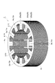
First, the configuration of the stator laminated
固定子積層鉄心1は、ヨーク部2(本体部)と、複数のティース部3とを有する。ヨーク部2は、円環状を呈しており、中心軸Axを囲むように延びている。ヨーク部2の径方向における幅、内径、外径及び厚さはそれぞれ、モータの用途及び性能に応じて種々の大きさに設定しうる。ヨーク部2の外周面には、中心軸Axに沿って延びる複数の凹溝2aが設けられている。凹溝2aは、固定子積層鉄心1の一方の端面(図1の上面)から他方の端面(図1の下面)に至るまで延びている。本実施形態では、3つの凹溝2aが中心軸Ax周りに略120°間隔で、ヨーク部2の外周面に設けられている。
The stator laminated
各ティース部3は、ヨーク部2の内縁から中心軸Ax側に向かうようにヨーク部2の径方向に沿って延びている。すなわち、各ティース部3は、ヨーク部2の内縁から中心軸Ax側に向けて突出している。固定子積層鉄心1においては、12個のティース部3がヨーク部2に一体的に形成されている。各ティース部3は、ヨーク部2の周方向において、略等間隔で並んでいる。隣り合うティース部3の間には、巻線(図示せず)を配置するための空間であるスロット4が画定されている。
Each
固定子積層鉄心1は、複数の加工板10(鉄心部材)が積み重ねられた積層体である。すなわち、加工板10は、固定子積層鉄心1と対応する形状を呈している。加工板10の中央部分には、貫通孔11aが設けられている。加工板10は、ヨーク部2に対応するヨーク片部12と、各ティース部3に対応する複数のティース片部13とを有している。ヨーク片部12の外周縁には、凹溝2aに対応する切欠部12aが設けられている。隣り合うティース片部13の間には、スロット4に対応するスロット14(貫通孔)が画定されている。
The stator laminated
積層方向(中心軸Axの延在方向)において隣り合う加工板10同士は、接着剤20によって接合されている。例えば、ヨーク片部12の表面には、ヨーク片部12の周方向に沿って略等間隔に並ぶようにスポット状の複数の接着剤20aが配置されている。本実施形態では、各接着剤20aは、各ティース片部13の基端部に対応する位置に配置されている。各ティース片部13の表面には、各ティース片部13にスポット状の接着剤20bが二つずつ配置されている。各ティース片部13における二つの接着剤20bは、ティース片部13の幅方向での中央部において、ティース片部13の延在方向(ヨーク片部12の径方向)に並んでいる。そのため、一つの接着剤20aと、当該接着剤20aに対応するティース片部13に配置されている二つの接着剤20bとは、ヨーク片部12の径方向において一列に並んでいる。これらの3つの接着剤20a,20b,20bの面積は、図1に示されるように中心軸Axから外方に向かうにつれて大きくなっていてもよいし、いずれも略同等であってもよいし、中心軸Axから外方に向かうにつれて小さくなっていてもよい。
The
[積層体の構成]
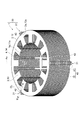
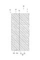
次に、図2〜図4を参照して、積層体30について説明する。積層体30は、固定子積層鉄心1の凹溝2aに仮カシメ部31が嵌合している状態のものである。積層体30は、複数の打抜部材40が積み重ねられてなる。すなわち、打抜部材40は、積層体30と対応する形状を呈している。換言すれば、打抜部材40は、仮カシメ部31に対応する仮カシメ片41が加工板10の切欠部12aに嵌合している状態のものである。
[Structure of laminate]
Next, the
仮カシメ片41と加工板10の切欠部12aとの間には、切断線CLが設けられている。各切断線CLは、例えば、電磁鋼板W(後述する)を切り曲げ加工又は打ち抜き加工した後、切り曲げ部分又は打ち抜き部分をプッシュバックして、元の電磁鋼板Wに圧入することにより、形成されてもよい。電磁鋼板Wが切り曲げ加工又は打抜き加工されると、切り曲げ部分又は打ち抜き部分が塑性変形して上型側(後述するパンチ133側)が若干延びるので、当該部分が元の電磁鋼板Wへ圧入されると、当該部分と元の電磁鋼板Wとは、人手では簡単に外れない程度にしっかりと嵌まり合う。
A cutting line CL is provided between the
積層方向において隣り合う打抜部材40同士は、仮カシメ片41を介して、仮カシメ片41に設けられた仮カシメ42によって締結されている。仮カシメ部31は、仮カシメ片41が積み重ねられた積層体であるともいえる。具体的には、仮カシメ42は、図3に示されるように、積層体30の最下層以外をなす打抜部材40の仮カシメ片41に形成された屈曲部42aと、積層体30の最下層をなす打抜部材40の仮カシメ片41に形成された貫通孔42bとを有する。屈曲部42aは、仮カシメ片41の表面側に形成された凹部と、仮カシメ片41の裏面側に形成された凸部とで構成されている。一の仮カシメ片41の屈曲部42aの凹部は、当該一の仮カシメ片41の表面側に隣り合う他の仮カシメ片41の屈曲部42aの凸部と接合される。一の仮カシメ片41の屈曲部42aの凸部は、当該一の仮カシメ片41の裏面側において隣り合う更に他の仮カシメ片41の屈曲部42aの凹部と接合される。貫通孔42bには、積層体30の最下層に隣接する打抜部材40の仮カシメ片41の屈曲部42aの凸部が接合される。貫通孔42bは、積層体30を連続して製造する際、既に製造された積層体30に対して次に製造する積層体30の仮カシメ部31が屈曲部42aによって締結されるのを防ぐ機能を有する。
The punching
打抜部材40は、例えば、電磁鋼板W(後述する)が加工(例えば、打ち抜き加工、切り曲げ加工等)されることにより得られる。打抜部材40の厚さは、モータの用途及び性能に応じて種々の大きさに設定しうるが、例えば、0.1mm〜0.5mm程度であってもよい。
The punching
積層体30は、いわゆる転積によって構成されていてもよい。「転積」とは、複数の打抜部材40を積層して積層体30を得るに際し、打抜部材40同士の角度を相対的にずらすことをいい、打抜部材40を回転させつつ積層することを含む。転積は、主に打抜部材40の板厚偏差を相殺することを目的に実施される。打抜部材40を得るにあたり、打抜部材40を1枚ごとに転積してもよいし、打抜部材40が所定枚数積層された単位ブロックごとに転積してもよい。転積の角度又は頻度は任意の値に設定してもよい。
The
[固定子積層鉄心の製造装置]
続いて、図5〜図10を参照して、固定子積層鉄心1の製造装置100について説明する。
[Stator laminated core manufacturing equipment]
Then, with reference to FIGS. 5-10, the
製造装置100は、帯状の金属板である電磁鋼板W(被加工板)から固定子積層鉄心1を製造するための装置である。製造装置100は、アンコイラー110と、送出装置120と、打抜装置130(金型)と、焼鈍炉140(オイル除去機構)と、仮カシメ除去装置150(仮カシメ除去機構)と、積層装置160と、コントローラ170(制御部)とを備える。
The
アンコイラー110は、コイル状に巻回された帯状の電磁鋼板Wであるコイル材111が装着された状態で、コイル材111を回転自在に保持する。コイル材111を構成する電磁鋼板Wの略全体には、パンチ133(後述する)の摩耗抑制、打抜部材40の打抜性向上等を目的としてオイルが塗布されている。送出装置120は、電磁鋼板Wを上下から挟み込む一対のローラ121,122を有する。一対のローラ121,122は、コントローラ170からの指示信号に基づいて回転及び停止し、電磁鋼板Wを打抜装置130に向けて間欠的に順次送り出す。
The
コイル材111を構成する電磁鋼板Wの長さは、例えば500m〜10000m程度であってもよい。電磁鋼板Wの厚さは、例えば0.1mm〜0.5mm程度であってもよい。電磁鋼板Wの厚さは、より優れた磁気的特性を有する固定子積層鉄心1を得る観点から、例えば0.1mm〜0.3mm程度であってもよい。電磁鋼板Wの幅は、例えば50mm〜500mm程度であってもよい。
The length of the electromagnetic steel sheet W that constitutes the
打抜装置130は、コントローラ170からの指示信号に基づいて動作する。打抜装置130は、送出装置120によって間欠的に送り出される電磁鋼板Wを順次打ち抜き加工して打抜部材40を形成する機能と、打ち抜き加工によって得られた打抜部材40を順次積層して積層体30を製造する機能とを有する。具体的には、打抜装置130は、図6に示されるように、下型131と、ダイプレート132と、ストリッパ(図示せず)と、上型(図示せず)と、パンチ133とを備える。
The
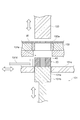
下型131は、下型131に載置されたダイプレート132を保持する。下型131には、電磁鋼板Wから打ち抜かれた打抜部材40が排出される排出孔131aが、パンチ133に対応する位置にそれぞれ設けられている。排出孔131a内には、図6及び図7に示されるように、シリンダ131bと、ステージ131cと、プッシャ131dとが配置されている。
The
図6に示されるように、コントローラ170からの指示信号に基づいてパンチ133が上下動して、ダイプレート132に保持されたダイ132a内にパンチ133が挿入されると、電磁鋼板Wから打抜部材40が打ち抜かれる。このとき、シリンダ131bは、パンチ133によって電磁鋼板Wから打ち抜かれた打抜部材40が下方に落下するのを防止するため、打抜部材40を弾性的に支持する。
As shown in FIG. 6, when the
シリンダ131bは、コントローラ170からの指示信号に基づいて上下方向に移動可能に構成されている。そのため、シリンダ131bは、シリンダ131b上に打抜部材40が積み重ねられるごとに間欠的に下方に移動する。シリンダ131b上において打抜部材40が所定枚数まで積層され、積層体30が形成されると、図7に示されるように、シリンダ131bの表面がステージ131cの表面と同一高さとなる位置にシリンダ131bが移動する。
The
ステージ131cには、シリンダ131bが通過可能な孔131eが設けられている。プッシャ131dは、コントローラ170からの指示信号に基づいて、ステージ131cの表面上において水平方向に移動可能に構成されている。シリンダ131bの表面がステージ131cの表面と同一高さとなる位置にシリンダ131bが移動した状態で、プッシャ131dは、積層体30をシリンダ131bからステージ131cに払い出す。ステージ131cに払い出された積層体30は、打抜装置130と焼鈍炉140との間を延びるように設けられたコンベアCv1に排出される。コンベアCv1は、コントローラ170からの指示に基づいて動作し、積層体30を焼鈍炉140に送り出す。
The
焼鈍炉140は、積層体30を所定温度(例えば、750℃〜800℃程度)で所定時間(例えば、1時間程度)加熱することにより、打抜部材40に付着しているオイルを蒸発させる(除去する)と共に打抜部材40の内部に残留している歪みを除去する機能を有する。焼鈍炉140から排出された積層体30は、焼鈍炉140と仮カシメ除去装置150との間を延びるように設けられたコンベアCv2に載置される。コンベアCv2は、コントローラ170からの指示に基づいて動作し、積層体30を仮カシメ除去装置150に送り出す。
The
仮カシメ除去装置150は、コンベアCv2から送られた積層体30から仮カシメ部31を除去する機能を有する。仮カシメ除去装置150で積層体30から仮カシメ部31が除去されると、隣り合う加工板10同士が接合されていない状態で複数の加工板10が積層された仮積層体50(図8参照)となる。仮カシメ除去装置150から排出された仮積層体50は、仮カシメ除去装置150と積層装置160との間を延びるように設けられたコンベアCv3に載置される。コンベアCv3は、コントローラ170からの指示に基づいて動作し、仮積層体50を積層装置160に送り出す。
The temporary
積層装置160は、コンベアCv3から送られた仮積層体50から加工板10を一つずつ取り出す機能と、加工板10に接着剤20を供給する機能と、接着剤20が供給された加工板10を他の加工板10に積み重ねる機能とを有する。積層装置160は、図8に示されるように、測定ユニット161(測定機構)と、供給ユニット162(供給機構)と、積層治具163(治具)と、ロボットハンド164(保持機構)とを有する。
The
測定ユニット161は、載置台161aと、測定機161bとを含む。測定機161bは、コントローラ170からの指示信号に基づいて動作して、載置台161aに載置されている一つの加工板10の厚さを測定する機能を有する。測定機161bは、加工板10のヨーク片部12の厚さを2箇所以上測定してもよい。測定機161bによって測定された測定データは、コントローラ170に送信される。測定機161bは、接触式であってもよいし、非接触式(例えば、レーザ測定機、撮像カメラ)であってもよい。測定機161bが撮像カメラである場合には、撮像カメラで撮像された加工板10の撮像画像に基づいてコントローラ170が画像処理を実行し、加工板10の厚さが計算される。
The measuring
供給ユニット162は、液源162aと、ポンプ162bと、供給ノズル162cと、配管162dとを含む。配管162dは、液源162a、ポンプ162b及び供給ノズル162cを上流側から下流側に向けてこの順に接続している。液源162aは、接着剤20の供給源として機能する。接着剤20としては、例えば、アクリル系又はエポキシ系の接着剤が用いられてもよい。接着剤20は、1液型の接着剤であってもよいし、2液混合型の接着剤であってもよい。ポンプ162bは、コントローラ170からの指示信号に基づいて動作し、液源162aから接着剤20を吸引し、配管162dを通じて供給ノズル162cに接着剤20を送り出す。
The
供給ノズル162cは、その吐出口が上方を向くように設けられている。そのため、供給ノズル162cの吐出口に到達した接着剤20は、加工板10の下面に供給される。この状態でコントローラ170によりポンプ162bが動作されると、加工板10の下面のうち所定箇所に接着剤20が供給される。接着剤20は、加工板10の下面に対して、スポット状に供給されてもよいし、拡がりをもって塗布されてもよい。加工板10に下面に対して供給される接着剤20の量は、複数の加工板10が積層されたときの圧力で加工板10同士の間からはみ出ない程度であってもよい。
The
供給ノズル162cは、加工板10のヨーク片部12及び各ティース片部13のうち接着剤20a,20bの供給予定領域に対応する数の吐出口を有していてもよい。この場合、各吐出口は、加工板10の中心軸Axから放射状に並んでいてもよい。中心軸Axの径方向において並ぶ複数の吐出口の開口面積は、中心軸Axから外方に向かうにつれて大きくなっていてもよいし、いずれも略同等であってもよいし、中心軸Axから外方に向かうにつれて小さくなっていてもよい。中心軸Ax側から外方に向けて順次各吐出口に接着剤20が供給されると、接着剤20が通常高い粘度を有しているので、下流側の吐出口から吐出される接着剤20の量が少なくなる懸念があるが、中心軸Axの径方向において並ぶ複数の吐出口の開口面積が中心軸Axから外方に向かうにつれて大きくなっている場合、各吐出口から吐出される接着剤20の量を均一化することが可能となる。これにより、加工板10を積層したときに加工板10から接着剤20がはみ出し難くなると共に接着剤20の供給ムラを抑制することができる。換言すれば、複数の吐出口のうち接着剤20の流路の下流側に位置する吐出口の開口面積ほど大きくなるように設定されていてもよい。
The
積層治具163は、台座163aと、挿通ポスト163bと、複数の挿通ピン163cとを含む。台座163aは略矩形状を呈する板状体である。挿通ポスト163b及び挿通ピン163cは、台座163aの上面から上方に向けて突出するように台座163aに設けられている。挿通ポスト163b及び挿通ピン163cの位置は、加工板10の貫通孔11a及びスロット14の位置に対応している。挿通ポスト163bは、円柱形状を呈しており、加工板10の貫通孔11aに対応する外形を有する。複数の挿通ピン163cは、挿通ポスト163bを取り囲むように挿通ポスト163bの外側に位置している。挿通ピン163cは、多角柱状を呈しており、加工板10のスロット14に対応する外形を有する。本実施形態では、挿通ピン163cの数が3つであるが、挿通ピン163cの数は、少なくとも一つであってもよく、加工板10のスロット14の数以下であってもよい。
The stacking
ロボットハンド164は、コントローラ170からの指示信号に基づいて動作する。ロボットハンド164は、仮積層体50のうち加工板10を一つ把持及び搬送可能に構成されている。具体的には、ロボットハンド164は、コンベアCv3によって搬送された仮積層体50のうちから一つの加工板10を把持し、当該加工板10を載置台161a上に載置する機能を有する。ロボットハンド164は、載置台161a上に載置されている一つの加工板10を把持し、当該加工板10の下面が供給ノズル162cの吐出口と対向するように当該加工板10を供給ノズル162cの上方に位置させる機能を有する。ロボットハンド164は、一つの加工板10を供給ノズル162cの上方に位置させた状態から、挿通ポスト163bが加工板10の貫通孔11aに挿通され且つ各挿通ピン163cが加工板10の対応するスロット14に挿通されるように、加工板10を積層治具163にセットする機能を有する。一の加工板10を積層治具163にセットする際、他の加工板10が積層治具163に既にセットされている場合には、当該一の加工板10は当該他の加工板10に対して積層される。
The
コントローラ170は、製造装置100を部分的又は全体的に制御する。コントローラ170は、図9に示されるように、機能モジュールとして、読取部M1と、記憶部M2と、処理部M3と、指示部M4とを有する。これらの機能モジュールは、コントローラ170の機能を便宜上複数のモジュールに区切ったものに過ぎず、コントローラ170を構成するハードウェアがこのようなモジュールに分かれていることを必ずしも意味するものではない。各機能モジュールは、プログラムの実行により実現されるものに限られず、専用の電気回路(例えば論理回路)、又は、これを集積した集積回路(ASIC:Application Specific Integrated Circuit)により実現されるものであってもよい。
The
読取部M1は、コンピュータ読み取り可能な記録媒体RMからプログラムを読み取る。記録媒体RMは、製造装置100に各種動作を実行させるためのプログラムを記録している。記録媒体RMとしては、例えば、半導体メモリ、光記録ディスク、磁気記録ディスク、光磁気記録ディスクであってもよい。
The reading unit M1 reads a program from the computer readable recording medium RM. The recording medium RM records a program for causing the
記憶部M2は、種々のデータを記憶する。記憶部M2は、例えば、読取部M1において読み取られたプログラムの他、例えば、外部入力装置(図示せず)を介してオペレータから入力された設定データ等を記憶する。 The storage unit M2 stores various data. The storage unit M2 stores, for example, setting data and the like input from an operator via an external input device (not shown), in addition to the program read by the reading unit M1.
処理部M3は、各種データを処理する。処理部M3は、例えば、記憶部M2に記憶されている各種データに基づいて、ローラ121,122、打抜装置130、焼鈍炉140、仮カシメ除去装置150、測定機161b、ロボットハンド164又はコンベアCv1〜Cv3を動作させるための信号を生成する。処理部M3は、測定機161bから受信した測定データに基づいて、当該測定データに対応する加工板10の転積の要否を判断する。処理部M3は、判断の結果が転積要であった場合、当該加工板10を転積させるための指示信号を生成する。
The processing unit M3 processes various data. The processing unit M3 is, for example, based on various data stored in the storage unit M2, the
指示部M4は、処理部M3において生成された信号を、ローラ121,122、打抜装置130、焼鈍炉140、仮カシメ除去装置150、測定機161b、ロボットハンド164又はコンベアCv1〜Cv3に送信する。
The instruction unit M4 transmits the signal generated in the processing unit M3 to the
コントローラ170のハードウェアは、例えば一つ又は複数の制御用のコンピュータにより構成される。コントローラ170は、ハードウェア上の構成として、例えば図10に示される回路E1を有する。回路E1は、電気回路要素(circuitry)で構成されていてもよい。回路E1は、具体的には、プロセッサE2と、メモリE3と、ストレージE4と、ドライバE5と、入出力ポートE6とを有する。プロセッサE2は、メモリE3及びストレージE4の少なくとも一方と協働してプログラムを実行し、入出力ポートE6を介した信号の入出力を実行することで、上述した各機能モジュールを構成する。ドライバE5は、製造装置100の各種装置をそれぞれ駆動する回路である。入出力ポートE6は、ドライバE5と製造装置100の各種装置との間で、信号の入出力を行う。
The hardware of the
本実施形態では、製造装置100は、一つのコントローラ170を備えているが、複数のコントローラ170で構成されるコントローラ群(制御部)を備えていてもよい。製造装置100がコントローラ群を備えている場合には、上記の機能モジュールがそれぞれ、一つのコントローラ170によって実現されていてもよいし、2個以上のコントローラ170の組み合わせによって実現されていてもよい。コントローラ170が複数のコンピュータ(回路E1)で構成されている場合には、上記の機能モジュールがそれぞれ、一つのコンピュータ(回路E1)によって実現されていてもよいし、2つ以上のコンピュータ(回路E1)の組み合わせによって実現されていてもよい。コントローラ170は、複数のプロセッサE2を有していてもよい。この場合、上記の機能モジュールがそれぞれ、一つのプロセッサE2によって実現されていてもよいし、2つ以上のプロセッサE2の組み合わせによって実現されていてもよい。
In the present embodiment, the
[回転子積層鉄心の製造方法]
続いて、図11を参照して、固定子積層鉄心1の製造方法について説明する。
[Method of manufacturing rotor laminated core]
Then, with reference to FIG. 11, the manufacturing method of the stator laminated
まず、積層体30を形成する(仮積層工程;仮積層処理;図11のステップS1参照)。具体的には、コントローラ170の指示に基づいて、送出装置120によって電磁鋼板Wを打抜装置130に送り出し、打抜装置130によって電磁鋼板Wの被加工部位を所定形状に打ち抜く。これにより、打抜部材40が形成される。この打抜加工を繰り返すことにより、複数の打抜部材40が互いに仮カシメ42によって締結されながら所定枚数積層されて、一つの積層体30が製造される。このとき、積層体30を構成する各打抜部材40にはオイルが付着している。
First, the laminate 30 is formed (temporary lamination process; temporary lamination process; see step S1 in FIG. 11). Specifically, based on the instruction of the
続いて、コントローラ170の指示に基づいて、打抜装置130から排出された積層体30をコンベアCv1が焼鈍炉140まで搬送する。焼鈍炉140は、コントローラ170の指示に基づいて積層体30を焼鈍処理する(オイル除去工程;オイル除去処理;図11のステップS2参照)。これにより、積層体30を構成する各打抜部材40に付着しているオイルが除去される。その後、コントローラ170の指示に基づいて、焼鈍炉140から排出された焼鈍処理済の積層体30をコンベアCv2が仮カシメ除去装置150まで搬送する。
Subsequently, the conveyor Cv1 conveys the stacked
続いて、仮カシメ除去装置150は、コントローラ170の指示に基づいて、積層体30から仮カシメ部31を除去する(分離工程;分離処理;図11のステップS3参照)。例えば、仮カシメ除去装置150は、積層体30のうち固定子積層鉄心1となる部分を固定し、仮カシメ部31に対して積層方向にピストン等で力を付与する。これにより、積層体30から仮カシメ部31が取り除かれ、隣り合う加工板10が締結されていない状態で複数の加工板10が積層された仮積層体50が形成される。その後、コントローラ170の指示に基づいて、仮カシメ除去装置150から排出された仮積層体50をコンベアCv3が積層装置160まで搬送する。
Subsequently, the temporary
続いて、コントローラ170の指示に基づいて、ロボットハンド164が仮積層体50から一つの加工板10を把持し、載置台161a上に載置する。次に、コントローラ170の指示に基づいて、載置台161a上の加工板10の厚さを測定機161bが測定する(図11のステップS4参照)。測定機161bは、例えば、仮カシメの個数に合わせて、ヨーク片部12の厚さを3箇所測定してもよい。当該測定箇所は、中心軸Ax周りに120°おきに設定されていてもよい。これにより、ヨーク片部12の3箇所の厚さが得られる。なお、測定箇所の数は、4箇所に限られず、2箇所以上であってもよい。測定位置は、中心軸Ax周りに等間隔であってもよいし、任意の間隔であってもよい。測定機161bは、加工板10の厚さを測定すると、測定データをコントローラ170に送信する。
Subsequently, based on the instruction of the
コントローラ170は、測定機161bから加工板10の測定データを受信すると、当該加工板10の転積の要否を判断する。具体的には、コントローラ170は、まず加工板10の積厚差を算出する。続いて、コントローラ170は、算出した積厚差が所定の閾値以下である場合には、当該加工板10の転積が不要であると判断する。一方、コントローラ170は、算出した積厚差が所定の閾値を超えている場合には、当該加工板10の転積が必要であると判断すると共に、それまでに積層治具163にセットされた加工板10の集合体に対して積厚差を打ち消すのに最も適した角度を算出する。なお、当該加工板10が積層治具163に対してセットされる最初の一つである場合には、コントローラ170は、当該加工板10の転積の要否を判断しなくてもよい。
When the
続いて、コントローラ170の指示に基づいて、ロボットハンド164が載置台161a上の加工板10を把持し、加工板10の下面が供給ノズル162cの吐出口と対向するように加工板10を供給ノズル162cの上方に位置させる。次に、コントローラ170の指示に基づいて、ロボットハンド164及びポンプ162bが同期して動作して、加工板10の下面のうち接着剤20の供給予定箇所が供給ノズル162cの吐出口に近接したときに、当該供給予定箇所に対して供給ノズル162cから接着剤20を例えばスポット状に供給する(本積層工程;本積層処理;図11のステップS5参照)。なお、当該加工板10が積層治具163に対してセットされる最初の一つである場合には、当該加工板10に対して接着剤20が供給されなくてもよい(ステップS5の処理が行われなくてもよい)。
Subsequently, based on the instruction of the
続いて、コントローラ170の指示に基づいて、ロボットハンド164が加工板10を供給ユニット162から積層治具163に搬送する。このとき、ステップS4において転積の要否が判断された結果、当該加工板10の転積が不要である場合には、ロボットハンド164は当該加工板10を回転させることなく積層治具163にセットする(本積層工程;本積層処理;図11のステップS6参照)。一方、ステップS4において転積の要否が判断された結果、当該加工板10の転積が必要である場合には、ロボットハンド164は、算出された角度に従って当該加工板10を回転させた後、当該加工板10を積層治具163にセットする(本積層工程;本積層処理;図11のステップS6参照)。加工板10が積層治具163にセットされる際には、挿通ポスト163bが加工板10の貫通孔11aに挿通され且つ各挿通ピン163cが加工板10の対応するスロット14に挿通される。
Subsequently, the
以上のステップS4〜S6の処理を、仮積層体50の加工板10の一つ一つに対して繰り返すことにより、各加工板10が積層治具163に対して一つ一つ積層される。その結果、複数の加工板10が積層されると共に隣り合う加工板10同士が接着剤によって接合されてなる固定子積層鉄心1が完成する。
The
[作用]
以上のような本実施形態では、打抜装置130において積層体30を形成した後に、積層体30のオイル除去と、各打抜部材40の接着及び転積とが打抜装置130外において行われる。そのため、オイルを除去する機構、接着剤を供給する機構及び加工板10を転積する機構を、打抜装置130内に設ける必要がない。従って、打抜装置130を小型化することが可能となる。その結果、電磁鋼板Wから打抜部材40を複数列一組で形成する、いわゆる「複数列取り」の打抜装置130とした場合や、固定子積層鉄心1及び回転子積層鉄心となる打抜部材40を同じ電磁鋼板Wから形成する、いわゆる「共取り」の打抜装置130とした場合でも、打抜装置130の大型化を抑制することができる。
[Effect]
In the present embodiment as described above, after the
ところで、特許文献1に記載の方法では金型内で接着剤が使用される。そのため、嫌気性の接着剤が用いられる場合、金型内の空気が遮断された領域で金属イオン結合が生じて接着剤が金型に付着してしまい、金型のクリーニングが必要となる。また、熱硬化性の接着剤が用いられる場合、金型内に加熱装置を設置する必要があり、金型が大型化してしまう。さらに、2液混合型の接着剤が用いられる場合、2つの液を金型内に導入するために、金型内に設置する塗布機構や配管に工夫が必要となる。そのため、特許文献1に記載の方法では、用いることのできる接着剤の種類に制約が生じうる。これに対して、本実施形態では、接着剤20の供給ユニット162が打抜装置130の外(金型外)にある。そのため、本実施形態によれば、周囲に金属性の部材が配置されていない限り、嫌気性の接着剤20を使用することができる。また、本実施形態によれば、熱硬化性や2液混合型の接着剤20を使用したとしても、金型による設置上の制約がない。従って、本実施形態は、特許文献1に記載の方法と比較して、接着剤20の選定上の制約が少なく、柔軟に対応することができる。
By the way, in the method described in
本実施形態では、隣り合う加工板10同士が接着剤20で接着されつつ積層されることにより固定子積層鉄心1が得られる。そのため、加工板10同士がカシメ、溶接等で締結されている場合と比較して、磁気特性の低下が生じ難い。従って、このような固定子積層鉄心1を用いてモータを製造することにより、モータ特性の向上を図ることが可能となる。特に近年、加工対象である電磁鋼板Wの厚さが薄くなってきており(例えば0.2mm〜0.25mm程度からそれ以下)、このような薄い電磁鋼板Wから得られる加工板10は極めて変形しやすいことから、加工板10同士を接着のみで接合する要望が高まってきている。そのため、本実施形態によれば、このような要望を、低コストで且つ効率的に固定子積層鉄心1を製造しつつ、このような要望をも満たすことが可能である。
In the present embodiment, the stator laminated
ところで、通常、オイルの除去処理及び接着剤20の供給処理は、打抜装置130において電磁鋼板Wを打ち抜いて打抜部材40を形成する処理よりも遅い。しかしながら、本実施形態では、焼鈍炉140及び供給ユニット162が打抜装置130外にある。そのため、打抜装置130と独立して焼鈍炉140及び供給ユニット162を複数設けることで、打抜装置130において打抜部材40の形成処理を高速に行いつつ、全体としてのスループットを向上させることができる。加えて、焼鈍炉140及び供給ユニット162は一般に打抜装置130よりも安価であるため、複数の打抜装置130により全体としてのスループットを向上させようとする場合と比較して、低コスト化が図られる。以上より、本実施形態によれば、低コストで且つ効率的に固定子積層鉄心1を製造することが可能となる。
By the way, the oil removal process and the adhesive 20 supply process are usually slower than the process of punching the electromagnetic steel sheet W in the
本実施形態では、打抜装置130で積層体30を形成し、その後、焼鈍炉140において積層体30からオイルを除去している。そのため、オイルの表面張力によって加工板10同士がくっつき合うことが抑制される。従って、後続の工程において仮積層体50から加工板10を一つずつ取り出しやすくなる。また、積層体30全体からオイルを除去しているので、一つ一つの加工板10からオイルを除去する場合と比較して、オイルの除去を効率的に行える。さらに、積層体30からオイルが除去されているので、接着剤20の接着性能に影響が生じ難くなる。
In the present embodiment, the
ところで、打抜装置130において電磁鋼板Wを打ち抜いて打抜部材40を形成すると、打抜部材40の周縁部が電磁鋼板Wから打ち抜かれる過程で打抜部材40には歪みが生じている。歪みを有する打抜部材40から得られた固定子積層鉄心1を用いてモータが製造されると、モータの特性に影響が生じうる。しかしながら、本実施形態では、積層体30を焼鈍することにより積層体30に付着しているオイルを除去している。そのため、オイルの除去と、打抜部材40からの歪みの緩和とが同時に行われる。従って、固定子積層鉄心1をより効率的に製造することが可能となる。これに対し、特許文献1に記載の方法では、接着剤が塗布された後の金属板を打ち抜いて、他の打抜部材に対して接着剤により接着させながら積層している。そのため、得られた積層体を焼鈍しようとすると、接着剤も高温(例えば、750℃〜800℃程度)に長時間(例えば、1時間程度)曝されてしまう。焼鈍の温度に耐えうる耐熱性を有する接着剤は、本願の出願時において存在していないか、入手することが極めて困難である。従って、特許文献1に記載の方法では、打抜部材に対して焼鈍処理することができず、打抜部材の歪みを緩和することができないので、モータ特性の低下が懸念される。しかしながら、本実施形態では、接着剤20の供給ユニット162が打抜装置130の外(金型外)にあり、積層体30の焼鈍後に接着剤が加工板10に供給されるので、接着剤20の選定上の制約を少なくすることができる。
By the way, when the electromagnetic steel sheet W is punched out in the
本実施形態では、測定機161bによって測定された加工板10の厚さに基づいて、コントローラ170が当該加工板10の転積の要否を判断している。そのため、一つずつの加工板10において転積の要否が判断される。従って、転積の自由度が高まるので、最終的な固定子積層鉄心1の寸法精度を向上させることが可能となる。
In the present embodiment, the
本実施形態では、打抜部材40同士を仮カシメ42によって互いに締結しつつ積層することにより積層体30が得られる。そのため、焼鈍炉140による焼鈍処理に際して、複数の打抜部材40を積層体30として一体的に取り扱える。また、本実施形態では、積層体30の焼鈍処理後に積層体30から仮カシメ部31を除去している。そのため、最終的な製品である固定子積層鉄心1には仮カシメ42が存在しておらず、加工板10同士が接着剤によって接合されている。従って、固定子積層鉄心1の製造過程における取り扱いの容易性の向上と、モータの特性の向上との両立を図ることが可能となる。
In the present embodiment, the
本実施形態では、挿通ポスト163bが加工板10の貫通孔11aに挿通され且つ各挿通ピン163cが加工板10の対応するスロット14に挿通されるように、各加工板10が積層治具163に順次積層される。そのため、加工板10の積層と同時に、加工板10が所定位置に位置決めされる。また、スロット14内に打抜カスが混入している場合には、挿通ピン163cがスロット14内に挿通される際に挿通ピン163cによって打抜カスが外部に排出される。従って、加工板10の積層時において打抜部材40の面内でずれが生じているか否か又はスロット14内に打抜カスが残存しているか否かを、加工板10の積層後に別途検査(この検査を「ゲージ通し検査」ということがある。)する必要がなくなる。その結果、固定子積層鉄心1をより効率的に製造することが可能となる。
In the present embodiment, each
ところで、図6に示されるように、パンチ133で電磁鋼板Wを打ち抜くと、打ち抜きの過程で電磁鋼板Wがパンチ133とダイ132aとの間で引き伸ばされ、電磁鋼板Wから打ち抜かれた打抜部材40の寸法がダイ132aよりも大きくなることがある。そのため、パンチ133が上方に移動すると打抜部材40がダイ132a内において山型に湾曲することがある。この場合、特許文献1に記載の方法のようにダイ132a内で打抜部材40同士を接着剤で接着しようとすると、打抜部材40の変形に抗して打抜部材40同士を接着するために、多量の接着剤を要する可能性がある。そうすると、打抜部材40同士の間に厚膜状の接着層が介在してしまい、最終的に製品として得られた固定子積層鉄心1の平坦性又は占積率(固定子積層鉄心1全体の体積のうち加工板10の体積が占める割合をいい、接着剤20の使用量が増えるほどこの値が低下する。)が損なわれうる。しかしながら、本実施形態では、打抜装置130から排出された後の仮積層体50から加工板10を一つずつ取り出して積層しているので、加工板10がダイ132aから拘束を受けていない。そのため、加工板10同士を接着するための接着剤20を少量とすることができると共に、最終的に製品として得られる固定子積層鉄心1の平坦性又は占積率を高めることが可能となる。さらには、固定子積層鉄心1の平行度及び直角度が高まり、固定子積層鉄心1の貫通孔1a内に配置される回転子積層鉄心との干渉が抑制されると共に、固定子積層鉄心1と回転子積層鉄心との組み付けを容易に行うことが可能となる。
By the way, as shown in FIG. 6, when the electromagnetic steel sheet W is punched by the
ところで、特許文献1に記載の方法では、接着剤が塗布された後の金属板を打ち抜いて、他の打抜部材に対して接着剤により接着させながら積層している。そのため、打抜部材の積層の途中で何らかの原因により製造装置が停止すると、時間の経過により接着剤が固化し、途中まで積層された打抜部材に対して新たな打抜部材を接着させることができなくなる。従って、途中まで積層された打抜部材の全てを廃棄しなければならない。しかしながら、本実施形態では、加工板10一つずつに対して接着剤20を供給しているので、何らかの原因で製造装置100が停止して、接着剤20が固化したとしても、一つの加工板10が廃棄されるだけですむ。そのため、本実施形態によれば、材料費のコストの削減及び歩留まりの向上が図られると共に、固定子積層鉄心1の不良の発生を抑制することが可能となる。
By the way, in the method described in
[他の実施形態]
以上、本開示に係る実施形態について詳細に説明したが、本発明の要旨の範囲内で種々の変形を上記の実施形態に加えてもよい。例えば、ステップS2においては、焼鈍処理以外の他の手法によって積層体30からオイルを除去してもよい。例えば、焼鈍に至らない温度(例えば、100℃〜550℃程度)及び時間(例えば30分から1時間程度)で積層体30を加熱(例えば、バーンオフ炉によるバーンオフ処理、ブルーイング炉によるブルーイング処理など)してもよいし、積層体30を溶剤(例えば、アセトンなど)に含浸してもよいし、積層体30に付着しているオイルをエアで吹き飛ばしてもよい。あるいは、積層体30を常温の環境に所定時間(例えば、1日間)放置して自然乾燥することにより、積層体30からオイルを除去してもよい。
[Other embodiments]
Although the embodiments according to the present disclosure have been described above in detail, various modifications may be added to the above embodiments within the scope of the present invention. For example, in step S2, the oil may be removed from the laminate 30 by a method other than annealing. For example, the laminate 30 is heated at a temperature (for example, about 100 ° C. to 550 ° C.) and for a time (for example, about 30 minutes to 1 hour) that do not reach annealing (for example, burn-off treatment with a burn-off furnace, brewing treatment with a brewing furnace, etc.) The laminate 30 may be impregnated with a solvent (for example, acetone or the like), or the oil adhering to the laminate 30 may be blown away with air. Alternatively, the oil may be removed from the laminate 30 by leaving the laminate 30 in a normal temperature environment for a predetermined time (for example, one day) and naturally drying.
ステップS3の後で且つステップS4の前に、加工板10に欠陥(例えば、傷、凹み、打痕、打抜カスなど)があるか否かを確認する処理を行ってもよい。具体的には、ロボットハンド164が仮積層体50から一つの加工板10を把持した後、撮像装置(例えば、カメラなど)で加工板10を撮像し、当該撮像画像をコントローラ170が画像処理することにより、加工板10の欠陥を検出してもよい。加工板10に欠陥があることが検出された場合、当該加工板10を廃棄してもよい。また、加工板10の欠陥が加工板10に残存する打抜カスである場合には、打抜カスをエアブローなどで除去してもよい。なお、特許文献1に記載の方法では、個々の打抜部材が接着及び積層された積層体が金型から排出されるので、いずれかの打抜部材に欠陥があるか否かを確認することはできない。
After step S3 and before step S4, processing may be performed to confirm whether or not the processed
ステップS3の後で且つステップS4の前に、加工板10の形状又は寸法を確認する処理を行ってもよい。具体的には、ロボットハンド164が仮積層体50から一つの加工板10を把持した後、撮像装置(例えば、カメラなど)で加工板10を撮像し、当該撮像画像をコントローラ170が画像処理することにより、加工板10が設計に沿った形状又は寸法となっているか否かを判断してもよい。確認対象とする形状又は寸法は、加工板10のうち重要な箇所に限定してもよい。なお、特許文献1に記載の方法では、個々の打抜部材が接着及び積層された積層体が金型から排出されるので、個々の打抜部材の形状又は寸法を確認することはできない。
After step S3 and before step S4, a process of confirming the shape or dimension of the
2つのコイル材111の端部同士を溶接により接合して用いてもよい。この場合、パンチ133でコイル材111同士の溶接部が打ち抜かれると、当該溶接部を含む打抜部材40が積層体30に混在する。このような積層体30から得られた固定子積層鉄心1を用いてモータが製造されると、モータの特性に影響が生じうる。そのため、第1の手段としては、ステップS3の後で且つステップS4の前に、加工板10に溶接部が存在しているか否かを確認する処理を行ってもよい。具体的には、ロボットハンド164が仮積層体50から一つの加工板10を把持した後、撮像装置(例えば、カメラなど)で加工板10を撮像し、当該撮像画像をコントローラ170が画像処理することにより、加工板10における溶接部の有無を判断してもよい。加工板10に溶接部があると判断された場合、当該加工板10を廃棄してもよい。あるいは、第2の手段としては、コイル材111同士の溶接部をパンチ133が打ち抜かないよう、パンチ133よりも上流側においてパンチ133(打抜部材40の外形に対応する領域、又は、打抜部材40の外形とパイロット孔とを含む領域)よりも大きな径の補助パンチにより当該溶接部を予め打ち抜いてもよい。この場合、電磁鋼板Wのうち溶接部に相当する領域がパンチ133に到達しても、電磁鋼板Wの当該領域には貫通孔が存在しているので、パンチ133が空振りし、打抜部材40が形成されない。以上によれば、電磁鋼板Wのうち溶接部が存在する領域のみが廃棄されるので、材料の損失が最小限に抑えられる。そのため、コストの低減及び歩留まりの向上を図ることが可能となる。なお、特許文献1に記載の方法では、個々の打抜部材が接着及び積層された積層体が金型から排出されるので、いずれかの打抜部材に溶接部があるか否かを事前に確認することはできない。そのため、特許文献1に記載の方法では、溶接部を含む打抜部材が混在した積層体全てを廃棄しなければならず、材料費のコスト増及び歩留まりの低下に繋がりうる。
The end portions of the two
ステップS5において、接着剤20を加工板10に供給する前又は供給した後に、接着性能の向上を図るために接着補助剤(例えば、硬化開始剤、硬化促進剤、プライマなど)を加工板10に供給してもよい。接着剤20の供給前に接着補助剤を加工板10に供給する場合には、接着補助剤を加工板10に供給した後の工程において、接着剤20を接着補助剤に重なるように供給してもよい。一方、接着剤20の供給後に接着補助剤を加工板10に供給する場合には、接着剤20を加工板10に供給した後の工程において、接着補助剤を接着剤20に重なるように供給してもよい。接着補助剤を用いる場合においても、上記実施形態によれば、接着補助剤の供給ユニットが打抜装置130の外(金型外)にあり、積層体30の焼鈍後に接着補助剤が加工板10に供給されるので、接着補助剤の選定上の制約を少なくすることができる。なお、接着補助剤を用いることにより、加工板10にオイルが残存した状態でも接着剤20の接着性能の低下を抑制することができる場合には、焼鈍等による積層体30の加熱処理(ステップS2)を省略してもよい。
In step S5, before or after the adhesive 20 is supplied to the
接着剤20の供給後に接着補助剤を加工板10に供給する場合には、加工板10に接着補助剤を塗布してもよいし、噴霧してもよい。この場合、接着補助剤を加工板10の上側から噴霧してもよいし、加工板10の下側から噴霧してもよい。
When the adhesion aiding agent is supplied to the
上記実施形態では、接着剤20を加工板10の下面側から供給する場合について説明したが、接着剤20を加工板10の上面側から供給してもよい。同様に、接着補助剤を加工板10の下面側から供給してもよいし、上面側から供給してもよい。
Although the case where the adhesive 20 is supplied from the lower surface side of the
接着補助剤又は接着剤20を加工板10に供給した後、接着補助剤又は接着剤20の位置及び/又は寸法(直径)を確認する処理を行ってもよい。具体的には、撮像装置(例えば、カメラなど)で加工板10を撮像し、当該撮像画像をコントローラ170が画像処理することにより、供給された接着補助剤又は接着剤20が設計に沿った位置にあるか又は設計に沿った寸法となっているか否かを判断してもよい。この場合、接着補助剤又は接着剤20に蛍光物質(例えば、ブラックライトに反応して発光する物質など)を含有させておき、加工板10に供給された接着補助剤又は接着剤20の視認性を高めてもよい。接着補助剤又は接着剤20の供給面を検査し、接着補助剤又は接着剤20が所望の位置又は寸法にない場合には、そのような加工板10を廃棄してもよいし、加工板10に対して接着補助剤又は接着剤20を再度供給してもよい。以上のようにすると、接着補助剤又は接着剤20の供給不良に起因する固定子積層鉄心1の不良の発生を抑制することが可能となる。具体的には、複数の加工板10が積層されたときの圧力で、接着補助剤又は接着剤20が加工板10同士の間からはみ出し難くなる。
After the adhesion adjuvant or the adhesive 20 is supplied to the
ステップS6の後に、得られた固定子積層鉄心1の積厚を測定し、次に製造される固定子積層鉄心1の転積又は積層にあたり当該測定結果を利用してもよい。例えば、固定子積層鉄心1が所望の積厚(所望の加工板10の積層枚数)に達していない場合、又は固定子積層鉄心1の積厚偏差が既定値を超えている場合、転積を考慮した新たな加工板10の積み増しを行ってもよい。これにより、固定子積層鉄心1の積厚又は積厚偏差を容易に調整でき、固定子積層鉄心1の不良の発生を抑制することが可能となる。
After step S6, the stack thickness of the obtained stator laminated
固定子積層鉄心1を構成する加工板10の積層枚数は、仮カシメ除去装置150から排出された仮積層体50を構成する加工板10の積層枚数と同じであってもよいし異なっていてもよい。
The number of laminations of the processed
上記実施形態では、仮積層体50から加工板10を一つずつ取り出し、一つずつの加工板10に接着剤20を供給したうえで、加工板10を一つずつ積層していたが、複数の加工板10が積層され且つこれらが互いに接合されたブロック体(鉄心部材)を一つずつ取り出し、一つずつのブロック体に接着剤20を供給した上で、ブロック体を一つずつ積層してもよい。この場合、ブロック体を構成する複数の加工板10は、仮カシメ部31によって互いに締結されていてもよいし、ヨーク片部12又はティース片部13に設けられたカシメによって互いに締結されていてもよいし、外周面が溶接されることによって互いに締結されていてもよい。ブロック体を構成する複数の加工板10がカシメ又は溶接により締結されている場合には、ステップS3が省略される。ステップS4では、ブロック体の積厚が測定された後に、一つずつのブロック体に対して転積の要否が判断され、ステップS6において、ブロック体が一つずつ積層治具163にセットされる。ステップS5では、ブロック体の下面又は上面に接着剤20又は接着補助剤が供給される。
In the above embodiment, after processing
加工板10の外周縁に凹部又は凸部が設けられており、積層治具163は当該凸部又は凹部と係合する係合ピンを含んでいてもよい。係合ピンは、台座163aの上面から上方に向けて突出している。この場合、係合ピンは、挿通ピン163cと共に加工板10の位置決めに利用される。積層治具163は、係合ピンを含む場合、挿通ピン163cを含んでいなくてもよい。
A recess or a protrusion is provided on the outer peripheral edge of the
上記実施形態では積層治具163が挿通ピン163cを含んでいたが、積層治具163が挿通ピン163cを含んでいなくてもよい。
Although the stacking
固定子積層鉄心1のみならず回転子積層鉄心に対しても、本発明を適用してもよい。
The present invention may be applied not only to the stator laminated
上記実施形態では、一枚の電磁鋼板Wを打ち抜く場合について説明したが、複数枚の電磁鋼板Wを同時に打ち抜く場合にも、本発明を適用してもよい。 Although the said embodiment demonstrated the case where the electromagnetic steel plate W of 1 sheet was pierced, the present invention may be applied also when punching out the electromagnetic steel plate W of two or more sheets simultaneously.
1…固定子積層鉄心、2a…凹溝、10…加工板、11a…貫通孔、12a…切欠部、14…スロット(貫通孔)、20,20a,20b…接着剤、30…積層体、31…仮カシメ部、40…打抜部材、41…仮カシメ片、42…仮カシメ、42a…屈曲部、42b…貫通孔、100…固定子積層鉄心の製造装置、130…打抜装置(金型)、140…焼鈍炉(オイル除去機構)、150…仮カシメ除去装置(仮カシメ除去機構)、160…積層装置、161…測定ユニット(測定機構)、162…供給ユニット(供給機構)、163…積層治具(治具)、163b…挿通ポスト、163c…挿通ピン、164…ロボットハンド(保持機構)、170…コントローラ(制御部)、CL…切断線、W…電磁鋼板。
DESCRIPTION OF
Claims (12)
前記積層体から前記鉄心部材を一つずつ取り出して、隣り合う前記鉄心部材同士の間に接着剤が位置するように個々の前記鉄心部材に接着剤を供給しつつ複数の前記鉄心部材を積層する本積層工程とを含む、積層鉄心の製造方法。 In the mold, a metal plate is punched along a predetermined shape to form an iron core member consisting of one punched member, or an iron core member which is a block body in which a plurality of punched members are joined together, A temporary laminating step of laminating the iron core members to form a laminated body;
The core members are taken out one by one from the laminate, and a plurality of the core members are laminated while supplying the adhesive to the individual core members such that the adhesive is positioned between the adjacent core members. A method of manufacturing a laminated core, comprising the present lamination step.
前記オイル除去工程でオイルが除去された前記積層体から前記鉄心部材を一つずつ取り出して個々の前記鉄心部材の厚さを測定することと、
前記鉄心部材の厚さの測定結果に基づいて個々の前記鉄心部材の転積の要否を判断することと、
転積の要否の判断結果に基づいて、隣り合う前記鉄心部材同士の間に接着剤が位置するように個々の前記鉄心部材に接着剤を供給しつつ複数の前記鉄心部材を積層することとを行う、請求項2又は3に記載の方法。 In the main lamination step,
Taking out the core members one by one from the laminate from which oil has been removed in the oil removing step and measuring the thickness of each of the core members;
Determining whether or not rolling of each of the core members is necessary based on the measurement result of the thickness of the core members;
Laminating a plurality of the iron core members while supplying the adhesive to the individual iron core members such that the adhesive is positioned between the adjacent iron core members based on the determination result of necessity of rolling and The method according to claim 2 or 3, wherein
前記仮積層工程の後で且つ前記本積層工程の前に、前記積層体から前記仮カシメを除去して前記鉄心部材同士を分離する分離工程をさらに含む、請求項1〜4のいずれか一項に記載の方法。 In the temporary laminating step, in the mold, a metal plate is punched along a predetermined shape to form a plurality of iron core members provided with temporary caulking, and a plurality of the iron core members are mutually fastened by the temporary caulking. Forming the laminate by laminating while
The method according to any one of claims 1 to 4, further comprising a separation step of removing the temporary caulking from the laminated body to separate the iron core members after the temporary lamination step and before the main lamination step. The method described in.
前記本積層工程では、前記複数の貫通孔のうちいずれか二つに対応する形状の挿通ピンを備える治具に対して、前記複数の貫通孔のうち前記挿通ピンに対応する貫通孔を当該挿通ピンに挿通させつつ複数の前記鉄心部材を順次積層させる、請求項1〜5のいずれか一項に記載の方法。 Each of the plurality of iron core members is provided with a plurality of through holes penetrating in the thickness direction,
In the final laminating step, a jig provided with an insertion pin having a shape corresponding to any two of the plurality of through holes is inserted into the through hole corresponding to the insertion pin among the plurality of through holes. The method according to any one of claims 1 to 5, wherein a plurality of the core members are sequentially stacked while being inserted into a pin.
前記鉄心部材を一つずつ保持可能に構成された保持機構と、
前記鉄心部材に接着剤を供給可能に構成された供給機構と、
制御部とを備え、
前記制御部は、
前記金型を制御して前記積層体を形成する仮積層処理と、
前記保持機構及び前記供給機構を制御して、前記積層体から前記保持機構により前記鉄心部材を一つずつ保持しつつ取り出して、隣り合う前記鉄心部材同士の間に接着剤が位置するように前記供給機構により個々の前記鉄心部材に接着剤を供給しつつ、前記保持機構により複数の前記鉄心部材を積層する本積層処理とを実行する、積層鉄心の製造装置。 A metal plate is punched along a predetermined shape to form an iron core member consisting of one punched member, or an iron core member which is a block body in which a plurality of punched members are joined to one another, and laminating the plural iron core members together. And a mold configured to form a laminate,
A holding mechanism configured to be able to hold the core members one by one;
A supply mechanism configured to be able to supply an adhesive to the core member;
And a control unit,
The control unit
Temporary lamination processing of controlling the mold to form the laminate;
The holding mechanism and the supply mechanism are controlled so that the iron core members are held out one by one from the laminate by the holding mechanism and the adhesive is positioned between the adjacent iron core members. A laminated iron core manufacturing apparatus, which performs an actual laminating process of laminating a plurality of the iron core members by the holding mechanism while supplying an adhesive to the individual iron core members by the supply mechanism.
前記制御部は、前記仮積層処理の後で且つ前記本積層処理の前に、前記オイル除去機構を制御して、前記金型から取り出された前記積層体に付着しているオイルを除去するオイル除去処理をさらに実行する、請求項7に記載の装置。 It further comprises an oil removal mechanism configured to remove oil adhering to the laminate,
The control unit controls the oil removing mechanism after the temporary stacking process and before the main stacking process to remove oil adhering to the stack taken out from the mold. The apparatus according to claim 7, further performing a removal process.
前記制御部は、前記本積層処理において、
前記保持機構及び前記測定機構を制御して、前記仮積層処理でオイルが除去された前記積層体から前記保持機構により前記鉄心部材を一つずつ取り出して個々の前記鉄心部材の厚さを測定することと、
前記測定機構による前記鉄心部材の厚さの測定結果に基づいて、個々の前記鉄心部材の転積の要否を判断することと、
転積の要否の判断結果に基づいて前記保持機構及び前記供給機構を制御して、隣り合う前記鉄心部材同士の間に接着剤が位置するように前記供給機構により個々の前記鉄心部材に接着剤を供給しつつ、前記保持機構により複数の前記鉄心部材を積層することとを実行する、請求項8又は9に記載の装置。 The apparatus further comprises a measurement mechanism configured to measure the thickness of the core member,
The control unit is configured to
The holding mechanism and the measuring mechanism are controlled to take out the iron core members one by one from the laminated body from which the oil has been removed by the temporary lamination process by the holding mechanism, and measure the thickness of each individual iron core member And
Determining whether or not rolling of each individual core member is necessary based on the measurement result of the thickness of the core member by the measurement mechanism;
The holding mechanism and the supply mechanism are controlled based on the determination result of necessity of rolling to bond the individual iron core members by the supply mechanism such that an adhesive is positioned between the adjacent core members. The apparatus according to claim 8 or 9, wherein laminating the plurality of core members is performed by the holding mechanism while supplying an agent.
前記積層体から仮カシメを除去する仮カシメ除去機構をさらに備え、
前記制御部は、前記仮カシメ除去機構を制御して、前記仮積層処理の後で且つ前記本積層処理の前に、前記積層体から前記仮カシメを除去して前記鉄心部材同士を分離する分離処理をさらに実行する、請求項7〜10のいずれか一項に記載の装置。 The metal mold is formed by punching a metal plate along a predetermined shape to form a plurality of iron core members provided with temporary caulking, and laminating the plurality of iron core members together by fastening them together with the temporary caulking. Configured to form a laminate,
The apparatus further comprises a temporary caulking removal mechanism for removing temporary caulking from the laminate,
The control unit controls the temporary caulking removal mechanism to separate the iron core members by removing the temporary caulking from the laminated body after the temporary laminating process and before the main laminating process. The apparatus according to any one of claims 7 to 10, further performing processing.
前記複数の貫通孔のうちいずれか二つに対応する形状の挿通ピンを備える治具をさらに備え、
前記制御部は、前記本積層処理において、前記複数の貫通孔のうち前記挿通ピンに対応する貫通孔を当該挿通ピンに挿通させつつ複数の鉄心部材を前記治具に対して順次積層させる、請求項7〜11のいずれか一項に記載の装置。 Each of the plurality of core members formed by the mold is provided with a plurality of through holes penetrating in the thickness direction,
The jig further includes an insertion pin having a shape corresponding to any two of the plurality of through holes,
The control unit is configured to sequentially stack a plurality of iron core members on the jig while inserting the through hole corresponding to the insertion pin among the plurality of through holes in the main stacking process through the insertion pin. Item 12. The device according to any one of items 7 to 11.
Priority Applications (5)
| Application Number | Priority Date | Filing Date | Title |
|---|---|---|---|
| JP2016249398A JP6543608B2 (en) | 2016-12-22 | 2016-12-22 | Method of manufacturing laminated core and apparatus for manufacturing laminated core |
| EP17884198.7A EP3562006A4 (en) | 2016-12-22 | 2017-10-10 | Laminated core manufacturing method and laminated core manufacturing device |
| PCT/JP2017/036677 WO2018116585A1 (en) | 2016-12-22 | 2017-10-10 | Laminated core manufacturing method and laminated core manufacturing device |
| CN201780078667.5A CN110100377B (en) | 2016-12-22 | 2017-10-10 | Method and apparatus for manufacturing laminated core |
| US16/447,889 US11196324B2 (en) | 2016-12-22 | 2019-06-20 | Method of manufacturing stacked core with adhesive |
Applications Claiming Priority (1)
| Application Number | Priority Date | Filing Date | Title |
|---|---|---|---|
| JP2016249398A JP6543608B2 (en) | 2016-12-22 | 2016-12-22 | Method of manufacturing laminated core and apparatus for manufacturing laminated core |
Publications (2)
| Publication Number | Publication Date |
|---|---|
| JP2018107852A JP2018107852A (en) | 2018-07-05 |
| JP6543608B2 true JP6543608B2 (en) | 2019-07-10 |
Family
ID=62626041
Family Applications (1)
| Application Number | Title | Priority Date | Filing Date |
|---|---|---|---|
| JP2016249398A Active JP6543608B2 (en) | 2016-12-22 | 2016-12-22 | Method of manufacturing laminated core and apparatus for manufacturing laminated core |
Country Status (5)
| Country | Link |
|---|---|
| US (1) | US11196324B2 (en) |
| EP (1) | EP3562006A4 (en) |
| JP (1) | JP6543608B2 (en) |
| CN (1) | CN110100377B (en) |
| WO (1) | WO2018116585A1 (en) |
Cited By (1)
| Publication number | Priority date | Publication date | Assignee | Title |
|---|---|---|---|---|
| JP2018143034A (en) * | 2017-02-27 | 2018-09-13 | 株式会社三井ハイテック | Manufacturing device for laminated iron core |
Families Citing this family (36)
| Publication number | Priority date | Publication date | Assignee | Title |
|---|---|---|---|---|
| JP6543608B2 (en) * | 2016-12-22 | 2019-07-10 | 株式会社三井ハイテック | Method of manufacturing laminated core and apparatus for manufacturing laminated core |
| JP7078425B2 (en) * | 2018-03-07 | 2022-05-31 | 株式会社三井ハイテック | Manufacturing method of laminated iron core |
| DE102018205806A1 (en) * | 2018-04-17 | 2019-10-17 | Siemens Aktiengesellschaft | Stator, electric machine, aircraft with an electric machine and method of manufacturing a stator |
| CN109358380B (en) * | 2018-11-07 | 2024-04-12 | 天津工业大学 | Short circuit turn angle sensor magnetic conduction ring shaping frock |
| JP7187287B2 (en) | 2018-11-30 | 2022-12-12 | 株式会社三井ハイテック | Laminated core product manufacturing method |
| JP7288201B2 (en) | 2018-12-17 | 2023-06-07 | 日本製鉄株式会社 | Laminated core and rotating electric machine |
| TWI725670B (en) | 2018-12-17 | 2021-04-21 | 日商日本製鐵股份有限公司 | Laminated iron core, its manufacturing method and rotating electric machine |
| CA3131659C (en) | 2018-12-17 | 2023-11-14 | Nippon Steel Corporation | Adhesively-laminated core for stator and electric motor |
| TWI742488B (en) * | 2018-12-17 | 2021-10-11 | 日商日本製鐵股份有限公司 | Adhesive laminated iron core for stator and rotating electric machine |
| WO2020129937A1 (en) | 2018-12-17 | 2020-06-25 | 日本製鉄株式会社 | Laminated core and rotating electric machine |
| WO2020129924A1 (en) | 2018-12-17 | 2020-06-25 | 日本製鉄株式会社 | Laminated core and rotating electric machine |
| KR102643516B1 (en) | 2018-12-17 | 2024-03-06 | 닛폰세이테츠 가부시키가이샤 | Laminated core and rotating electric machines |
| US11979059B2 (en) | 2018-12-17 | 2024-05-07 | Nippon Steel Corporation | Laminated core and electric motor |
| US12068097B2 (en) | 2018-12-17 | 2024-08-20 | Nippon Steel Corporation | Laminated core, core block, electric motor and method of producing core block |
| EP3902108B1 (en) | 2018-12-17 | 2024-06-12 | Nippon Steel Corporation | Laminated core and rotating electric machine |
| SG11202108984XA (en) | 2018-12-17 | 2021-09-29 | Nippon Steel Corp | Adhesively-laminated core, manufacturing method therof, and electric motor |
| PL3902122T3 (en) | 2018-12-17 | 2024-06-24 | Nippon Steel Corporation | Laminated core and electric motor |
| WO2020129946A1 (en) * | 2018-12-17 | 2020-06-25 | 日本製鉄株式会社 | Glue lamination core for stators and method for manufacturing same, and rotating electrical machine |
| JP7412351B2 (en) | 2018-12-17 | 2024-01-12 | 日本製鉄株式会社 | Laminated core and rotating electrical machinery |
| RS65426B1 (en) * | 2018-12-18 | 2024-05-31 | Three Bond Co Ltd | Method for manufacturing laminated steel plate and device for manufacturing laminated steel plate |
| EP3736062A1 (en) | 2019-05-08 | 2020-11-11 | voestalpine Stahl GmbH | Method for stamp packaging of metal parts to stacks of metal sheets |
| JP7401996B2 (en) * | 2019-08-30 | 2023-12-20 | 株式会社三井ハイテック | Metal product dispensing device and metal product manufacturing method |
| CN110829755B (en) * | 2019-12-05 | 2024-06-25 | 苏州艾尔拓机电有限公司 | Stator piece stacking, positioning and ejecting device |
| JP2021097491A (en) * | 2019-12-17 | 2021-06-24 | 日本電産株式会社 | Stator manufacturing line and stator manufacturing method |
| IT202000003602A1 (en) * | 2020-02-21 | 2021-08-21 | Euro Group S P A | CLAMPING DEVICE FOR LAMELLAR PACKS |
| EP3876403A1 (en) | 2020-03-02 | 2021-09-08 | voestalpine Stahl GmbH | Method for packaging of metal parts to stacks of metal sheets |
| JP2021158852A (en) * | 2020-03-27 | 2021-10-07 | 日本電産株式会社 | Stacked body manufacturing apparatus and stacked body manufacturing method |
| CN115398776A (en) * | 2020-04-01 | 2022-11-25 | 发那科株式会社 | Stator, rotor, and rotating electrical machine |
| CN112071622B (en) * | 2020-09-12 | 2022-07-12 | 哈尔滨理工大学 | Transformer core silicon steel sheet laminating device and method |
| WO2022064724A1 (en) * | 2020-09-24 | 2022-03-31 | 日本電産株式会社 | Layered body manufacturing device and layered body manufacturing method |
| EP4060882A1 (en) * | 2021-03-16 | 2022-09-21 | Siemens Aktiengesellschaft | Magnetic sheet stack, method for producing same and electrical machine |
| EP4071776A1 (en) * | 2021-04-08 | 2022-10-12 | Siemens Aktiengesellschaft | Printing screen and method for providing a printing screen |
| CA3214720A1 (en) * | 2021-04-14 | 2022-10-20 | Nippon Steel Corporation | Bonded and stacked core manufacturing method and bonded and stacked core manufacturing apparatus |
| JP7174191B1 (en) | 2022-07-20 | 2022-11-17 | 田中精密工業株式会社 | Laminate dispensing device and laminate dispensing method |
| CN115632528B (en) * | 2022-12-21 | 2023-03-28 | 苏州范斯特机械科技有限公司 | Production equipment and production method of motor laminated iron core |
| CN117353529B (en) * | 2023-12-05 | 2024-02-20 | 御马精密科技(江苏)股份有限公司 | Production equipment and production method for stator and rotor iron cores of motor |
Family Cites Families (17)
| Publication number | Priority date | Publication date | Assignee | Title |
|---|---|---|---|---|
| JPS59162741A (en) * | 1983-03-07 | 1984-09-13 | Hitachi Ltd | Manufacture of laminated core |
| US5649349A (en) * | 1995-05-05 | 1997-07-22 | Greenway; Glenn W. | Method for manufacturing of laminated components |
| JP3466864B2 (en) * | 1997-03-31 | 2003-11-17 | 三菱電機株式会社 | Rotor of cage induction motor and method of manufacturing the same |
| WO2003031681A1 (en) * | 2001-10-05 | 2003-04-17 | Nippon Steel Corporation | Iron core exhibiting excellent insulating property at end face, and method for coating end face of iron core |
| US6877214B2 (en) * | 2002-11-05 | 2005-04-12 | L. H. Carbide Corporation | Method of manufacturing a stack of laminations |
| JP2005019643A (en) * | 2003-06-25 | 2005-01-20 | Jfe Steel Kk | Laminated core excellent in dimensional accuracy and its manufacturing method |
| JP4648765B2 (en) | 2005-06-03 | 2011-03-09 | 黒田精工株式会社 | Method for producing metal sheet laminate |
| WO2010082465A1 (en) * | 2009-01-14 | 2010-07-22 | 三菱電機株式会社 | Method for manufacturing laminated core and tool for manufacturing same |
| JP5991241B2 (en) * | 2013-03-15 | 2016-09-14 | アイシン・エィ・ダブリュ株式会社 | Core manufacturing method |
| JP6406788B2 (en) * | 2014-01-10 | 2018-10-17 | 株式会社三井ハイテック | Manufacturing method of laminated iron core |
| JP6162656B2 (en) * | 2014-07-09 | 2017-07-12 | 株式会社三井ハイテック | Rotor laminated iron core and manufacturing method thereof |
| US10201844B2 (en) * | 2014-11-07 | 2019-02-12 | Kuroda Precision Industries Ltd. | Apparatus and method for manufacturing laminated iron core |
| WO2016076321A1 (en) * | 2014-11-14 | 2016-05-19 | 株式会社三井ハイテック | Laminated core and method for manufacturing same |
| JP6343556B2 (en) * | 2014-12-09 | 2018-06-13 | 株式会社三井ハイテック | Laminated body for laminated iron core, method for producing the same, and method for producing laminated iron core |
| KR101876292B1 (en) * | 2016-03-18 | 2018-07-10 | 주식회사 포스코대우 | Adhesive Type Laminate Core Manufacturing Apparatus And Core Laminator Thereof |
| JP6543608B2 (en) * | 2016-12-22 | 2019-07-10 | 株式会社三井ハイテック | Method of manufacturing laminated core and apparatus for manufacturing laminated core |
| CN111002652A (en) * | 2018-10-05 | 2020-04-14 | 株式会社三井高科技 | Method for producing laminate and apparatus for producing laminate |
-
2016
- 2016-12-22 JP JP2016249398A patent/JP6543608B2/en active Active
-
2017
- 2017-10-10 EP EP17884198.7A patent/EP3562006A4/en active Pending
- 2017-10-10 WO PCT/JP2017/036677 patent/WO2018116585A1/en unknown
- 2017-10-10 CN CN201780078667.5A patent/CN110100377B/en active Active
-
2019
- 2019-06-20 US US16/447,889 patent/US11196324B2/en active Active
Cited By (1)
| Publication number | Priority date | Publication date | Assignee | Title |
|---|---|---|---|---|
| JP2018143034A (en) * | 2017-02-27 | 2018-09-13 | 株式会社三井ハイテック | Manufacturing device for laminated iron core |
Also Published As
| Publication number | Publication date |
|---|---|
| WO2018116585A1 (en) | 2018-06-28 |
| EP3562006A1 (en) | 2019-10-30 |
| CN110100377B (en) | 2022-07-29 |
| US11196324B2 (en) | 2021-12-07 |
| JP2018107852A (en) | 2018-07-05 |
| US20190305654A1 (en) | 2019-10-03 |
| EP3562006A4 (en) | 2020-07-29 |
| CN110100377A (en) | 2019-08-06 |
Similar Documents
| Publication | Publication Date | Title |
|---|---|---|
| JP6543608B2 (en) | Method of manufacturing laminated core and apparatus for manufacturing laminated core | |
| JP6781643B2 (en) | Laminated iron core manufacturing equipment | |
| JP6457969B2 (en) | Manufacturing method of laminated iron core | |
| JP5802818B1 (en) | Progressive processing method | |
| JP4856923B2 (en) | Rotating punching device and punching method for plate material | |
| JP2018129981A (en) | Manufacturing installation of laminated iron core and manufacturing method of laminated iron core | |
| US20190372439A1 (en) | Method of manufacturing stacked core and apparatus for manufacturing stacked core | |
| JP2017022885A (en) | Manufacturing method of laminated core and manufacturing device therefor | |
| CN110710088A (en) | Tool and method for manufacturing laminate | |
| JP6438731B2 (en) | Punching method, punching apparatus, and method for manufacturing laminated iron core | |
| JP2001185433A (en) | Iron core manufacturing method and apparatus suiting same | |
| JP2019054727A (en) | Method for manufacturing laminated iron core | |
| US20230291287A1 (en) | Laminated iron core, manufacturing method of laminated iron core, and progressive die machine | |
| JP6392089B2 (en) | Punching method, punching apparatus, and method for manufacturing laminated iron core | |
| TW202130098A (en) | Adhesive coating device, laminated iron core manufacturing device comprising said adhesive coating device, and method for manufacturing laminated iron core | |
| JP6630123B2 (en) | Laminated core and method of manufacturing the same | |
| US20230129627A1 (en) | Manufacturing method for laminated core of rotating electric machine, and manufacturing apparatus for laminated core of rotating electric machine | |
| JP7137918B2 (en) | Laminated core manufacturing method | |
| JP7316527B2 (en) | Motor core manufacturing method | |
| JP6010670B2 (en) | Progressive processing method | |
| JP6063533B2 (en) | Progressive processing method | |
| JP7466818B1 (en) | Apparatus and method for manufacturing laminate | |
| WO2024080316A1 (en) | Stacked body manufacturing device, and stacked body manufacturing method | |
| JP5016650B2 (en) | Method for manufacturing unit laminated body for annular laminated iron core | |
| JP2724530B2 (en) | Iron core manufacturing method and iron core manufacturing apparatus |
Legal Events
| Date | Code | Title | Description |
|---|---|---|---|
| A621 | Written request for application examination |
Free format text: JAPANESE INTERMEDIATE CODE: A621 Effective date: 20181220 |
|
| A871 | Explanation of circumstances concerning accelerated examination |
Free format text: JAPANESE INTERMEDIATE CODE: A871 Effective date: 20181220 |
|
| A975 | Report on accelerated examination |
Free format text: JAPANESE INTERMEDIATE CODE: A971005 Effective date: 20190124 |
|
| A131 | Notification of reasons for refusal |
Free format text: JAPANESE INTERMEDIATE CODE: A131 Effective date: 20190305 |
|
| A521 | Request for written amendment filed |
Free format text: JAPANESE INTERMEDIATE CODE: A523 Effective date: 20190408 |
|
| TRDD | Decision of grant or rejection written | ||
| A01 | Written decision to grant a patent or to grant a registration (utility model) |
Free format text: JAPANESE INTERMEDIATE CODE: A01 Effective date: 20190604 |
|
| A61 | First payment of annual fees (during grant procedure) |
Free format text: JAPANESE INTERMEDIATE CODE: A61 Effective date: 20190617 |
|
| R150 | Certificate of patent or registration of utility model |
Ref document number: 6543608 Country of ref document: JP Free format text: JAPANESE INTERMEDIATE CODE: R150 |
|
| R250 | Receipt of annual fees |
Free format text: JAPANESE INTERMEDIATE CODE: R250 |
|
| R250 | Receipt of annual fees |
Free format text: JAPANESE INTERMEDIATE CODE: R250 |
|
| R250 | Receipt of annual fees |
Free format text: JAPANESE INTERMEDIATE CODE: R250 |