EP3902109A1 - Laminated core and rotating machine - Google Patents
Laminated core and rotating machine Download PDFInfo
- Publication number
- EP3902109A1 EP3902109A1 EP19899146.5A EP19899146A EP3902109A1 EP 3902109 A1 EP3902109 A1 EP 3902109A1 EP 19899146 A EP19899146 A EP 19899146A EP 3902109 A1 EP3902109 A1 EP 3902109A1
- Authority
- EP
- European Patent Office
- Prior art keywords
- adhesion
- electrical steel
- core
- parts
- back part
- Prior art date
- Legal status (The legal status is an assumption and is not a legal conclusion. Google has not performed a legal analysis and makes no representation as to the accuracy of the status listed.)
- Pending
Links
Images




Classifications
-
- H—ELECTRICITY
- H02—GENERATION; CONVERSION OR DISTRIBUTION OF ELECTRIC POWER
- H02K—DYNAMO-ELECTRIC MACHINES
- H02K1/00—Details of the magnetic circuit
- H02K1/06—Details of the magnetic circuit characterised by the shape, form or construction
- H02K1/12—Stationary parts of the magnetic circuit
- H02K1/18—Means for mounting or fastening magnetic stationary parts on to, or to, the stator structures
- H02K1/185—Means for mounting or fastening magnetic stationary parts on to, or to, the stator structures to outer stators
-
- H—ELECTRICITY
- H01—ELECTRIC ELEMENTS
- H01F—MAGNETS; INDUCTANCES; TRANSFORMERS; SELECTION OF MATERIALS FOR THEIR MAGNETIC PROPERTIES
- H01F27/00—Details of transformers or inductances, in general
- H01F27/24—Magnetic cores
- H01F27/245—Magnetic cores made from sheets, e.g. grain-oriented
-
- C—CHEMISTRY; METALLURGY
- C09—DYES; PAINTS; POLISHES; NATURAL RESINS; ADHESIVES; COMPOSITIONS NOT OTHERWISE PROVIDED FOR; APPLICATIONS OF MATERIALS NOT OTHERWISE PROVIDED FOR
- C09J—ADHESIVES; NON-MECHANICAL ASPECTS OF ADHESIVE PROCESSES IN GENERAL; ADHESIVE PROCESSES NOT PROVIDED FOR ELSEWHERE; USE OF MATERIALS AS ADHESIVES
- C09J133/00—Adhesives based on homopolymers or copolymers of compounds having one or more unsaturated aliphatic radicals, each having only one carbon-to-carbon double bond, and at least one being terminated by only one carboxyl radical, or of salts, anhydrides, esters, amides, imides, or nitriles thereof; Adhesives based on derivatives of such polymers
- C09J133/04—Homopolymers or copolymers of esters
-
- C—CHEMISTRY; METALLURGY
- C09—DYES; PAINTS; POLISHES; NATURAL RESINS; ADHESIVES; COMPOSITIONS NOT OTHERWISE PROVIDED FOR; APPLICATIONS OF MATERIALS NOT OTHERWISE PROVIDED FOR
- C09J—ADHESIVES; NON-MECHANICAL ASPECTS OF ADHESIVE PROCESSES IN GENERAL; ADHESIVE PROCESSES NOT PROVIDED FOR ELSEWHERE; USE OF MATERIALS AS ADHESIVES
- C09J133/00—Adhesives based on homopolymers or copolymers of compounds having one or more unsaturated aliphatic radicals, each having only one carbon-to-carbon double bond, and at least one being terminated by only one carboxyl radical, or of salts, anhydrides, esters, amides, imides, or nitriles thereof; Adhesives based on derivatives of such polymers
- C09J133/04—Homopolymers or copolymers of esters
- C09J133/06—Homopolymers or copolymers of esters of esters containing only carbon, hydrogen and oxygen, the oxygen atom being present only as part of the carboxyl radical
- C09J133/08—Homopolymers or copolymers of acrylic acid esters
-
- C—CHEMISTRY; METALLURGY
- C09—DYES; PAINTS; POLISHES; NATURAL RESINS; ADHESIVES; COMPOSITIONS NOT OTHERWISE PROVIDED FOR; APPLICATIONS OF MATERIALS NOT OTHERWISE PROVIDED FOR
- C09J—ADHESIVES; NON-MECHANICAL ASPECTS OF ADHESIVE PROCESSES IN GENERAL; ADHESIVE PROCESSES NOT PROVIDED FOR ELSEWHERE; USE OF MATERIALS AS ADHESIVES
- C09J163/00—Adhesives based on epoxy resins; Adhesives based on derivatives of epoxy resins
-
- H—ELECTRICITY
- H02—GENERATION; CONVERSION OR DISTRIBUTION OF ELECTRIC POWER
- H02K—DYNAMO-ELECTRIC MACHINES
- H02K1/00—Details of the magnetic circuit
- H02K1/06—Details of the magnetic circuit characterised by the shape, form or construction
- H02K1/12—Stationary parts of the magnetic circuit
-
- H—ELECTRICITY
- H02—GENERATION; CONVERSION OR DISTRIBUTION OF ELECTRIC POWER
- H02K—DYNAMO-ELECTRIC MACHINES
- H02K1/00—Details of the magnetic circuit
- H02K1/06—Details of the magnetic circuit characterised by the shape, form or construction
- H02K1/12—Stationary parts of the magnetic circuit
- H02K1/14—Stator cores with salient poles
- H02K1/146—Stator cores with salient poles consisting of a generally annular yoke with salient poles
-
- H—ELECTRICITY
- H02—GENERATION; CONVERSION OR DISTRIBUTION OF ELECTRIC POWER
- H02K—DYNAMO-ELECTRIC MACHINES
- H02K1/00—Details of the magnetic circuit
- H02K1/06—Details of the magnetic circuit characterised by the shape, form or construction
- H02K1/12—Stationary parts of the magnetic circuit
- H02K1/18—Means for mounting or fastening magnetic stationary parts on to, or to, the stator structures
-
- H—ELECTRICITY
- H02—GENERATION; CONVERSION OR DISTRIBUTION OF ELECTRIC POWER
- H02K—DYNAMO-ELECTRIC MACHINES
- H02K15/00—Processes or apparatus specially adapted for manufacturing, assembling, maintaining or repairing of dynamo-electric machines
- H02K15/02—Processes or apparatus specially adapted for manufacturing, assembling, maintaining or repairing of dynamo-electric machines of stator or rotor bodies
-
- C—CHEMISTRY; METALLURGY
- C09—DYES; PAINTS; POLISHES; NATURAL RESINS; ADHESIVES; COMPOSITIONS NOT OTHERWISE PROVIDED FOR; APPLICATIONS OF MATERIALS NOT OTHERWISE PROVIDED FOR
- C09J—ADHESIVES; NON-MECHANICAL ASPECTS OF ADHESIVE PROCESSES IN GENERAL; ADHESIVE PROCESSES NOT PROVIDED FOR ELSEWHERE; USE OF MATERIALS AS ADHESIVES
- C09J2203/00—Applications of adhesives in processes or use of adhesives in the form of films or foils
- C09J2203/326—Applications of adhesives in processes or use of adhesives in the form of films or foils for bonding electronic components such as wafers, chips or semiconductors
-
- H—ELECTRICITY
- H02—GENERATION; CONVERSION OR DISTRIBUTION OF ELECTRIC POWER
- H02K—DYNAMO-ELECTRIC MACHINES
- H02K2201/00—Specific aspects not provided for in the other groups of this subclass relating to the magnetic circuits
- H02K2201/09—Magnetic cores comprising laminations characterised by being fastened by caulking
-
- H—ELECTRICITY
- H02—GENERATION; CONVERSION OR DISTRIBUTION OF ELECTRIC POWER
- H02K—DYNAMO-ELECTRIC MACHINES
- H02K2213/00—Specific aspects, not otherwise provided for and not covered by codes H02K2201/00 - H02K2211/00
- H02K2213/03—Machines characterised by numerical values, ranges, mathematical expressions or similar information
-
- Y—GENERAL TAGGING OF NEW TECHNOLOGICAL DEVELOPMENTS; GENERAL TAGGING OF CROSS-SECTIONAL TECHNOLOGIES SPANNING OVER SEVERAL SECTIONS OF THE IPC; TECHNICAL SUBJECTS COVERED BY FORMER USPC CROSS-REFERENCE ART COLLECTIONS [XRACs] AND DIGESTS
- Y02—TECHNOLOGIES OR APPLICATIONS FOR MITIGATION OR ADAPTATION AGAINST CLIMATE CHANGE
- Y02T—CLIMATE CHANGE MITIGATION TECHNOLOGIES RELATED TO TRANSPORTATION
- Y02T10/00—Road transport of goods or passengers
- Y02T10/60—Other road transportation technologies with climate change mitigation effect
- Y02T10/64—Electric machine technologies in electromobility
Definitions
- the present invention relates to a laminated core and an electric motor.
- Patent Document 1 a laminated core as described in Patent Document 1 below is known.
- electrical steel sheets adjacent in a stacking direction are adhered to each other by an adhesion layer.
- the present invention has been made in view of the above circumstances, and an object of the present invention is to improve the magnetic properties.
- a first aspect of the present invention is a laminated core that includes a plurality of electrical steel sheets stacked in a thickness direction, wherein each of the electrical steel sheets includes an annular core back part; an adhesion region is formed on an outer circumferential side of the core back part; a non-adhesion region is formed on an inner circumferential side of the core back part; and a plurality of fastening parts are provided in the non-adhesion region of the core back part at intervals in a circumferential direction.
- an adhesive shrinks during curing. Therefore, when an adhesive is provided in an electrical steel sheet, a compressive stress is applied to the electrical steel sheet as the adhesive cures. When a compressive stress is applied, a strain occurs in the electrical steel sheet. Further, when fastening parts are provided on the electrical steel sheet, the electrical steel sheet is deformed, and thus a strain occurs in the electrical steel sheet.
- the fastening parts and the adhesion region form a fixing part.
- the fixing part fixes electrical steel sheets adjacent in the stacking direction to each other. As the area of the fixing part increases, the strain of the electrical steel sheet increases.
- the adhesion region in which the adhesion part that is, for example, an adhesive is provided is formed on only the outer circumferential side of the core back part. Therefore, the core back parts of the electrical steel sheets adjacent in the stacking direction are partially adhered to each other. Therefore, the area of the adhesion region formed in the core back part is reduced as compared with, for example, a case in which the adhesion region extends inward in the radial direction to the fastening part. Therefore, the area of the fixing part in a plan view in the stacking direction is reduced. Accordingly, the strain that occurs in the entire laminated core can be made smaller. As a result, the iron loss that is generated in the laminated core can be reduced, and the magnetic properties of the laminated core can be improved.
- the outer circumferential side of the core back part may be an outside of outer circumferential edges of the fastening parts; and the inner circumferential side of the core back part may be an inside of the outer circumferential edges of the fastening parts.
- the outer circumferential side of the core back parts may be an outside of a virtual circle formed on an outer circumferential side of the outer circumferential edges of the fastening parts; and the inner circumferential side of the core back part may be an inside of the virtual circle.
- the adhesion region is not provided in the tooth parts. Therefore, the area of the fixing part is further reduced. Accordingly, the strain that occurs in the laminated core can be made smaller.
- the adhesion regions may be formed at least in the vicinity of the fastening parts in the outer circumferential edge of the core back part.
- the adhesion parts are provided discontinuously (intermittently) at intervals without being continuously provided over the entire circumference of the outer edge of the core back part. Therefore, the area of the adhesion regions formed in the core back part is reduced as compared with, for example, a case in which the adhesion regions are formed over the entire circumference. Accordingly, the area of the fixing part is further reduced. Therefore, the strain that occurs in the entire laminated core can be made smaller.
- the laminated core according to any one of claims (1) to (4) may further include an adhesion part which is provided in the adhesion region of the core back part between the electrical steel sheets adjacent in the stacking direction and adheres the core back parts adjacent in the stacking direction to each other.
- an average thickness of the adhesion parts may be 1.0 ⁇ m to 3.0 ⁇ m.
- an average tensile modulus of elasticity E of the adhesion parts may be 1500 MPa to 4500 MPa.
- the adhesion part may be a room temperature adhesion type acrylic-based adhesive including SGA made of an elastomer-containing acrylic-based adhesive.
- a second aspect of the present invention is an electric motor including the laminated core according to any one of (1) to (8).
- a motor specifically, an AC motor will be described as an example of the electric motor.
- the AC motor is more specifically a synchronous motor, and further more specifically a permanent magnetic electric motor.
- This type of motor is suitably employed for, for example, an electric vehicle and the like.
- an electric motor 10 includes a stator 20, a rotor 30, a case 50, and a rotary shaft 60.
- the stator 20 and the rotor 30 are housed in the case 50.
- the stator 20 is fixed to the case 50.
- the electric motor 10 an inner rotor type electric motor in which the rotor 30 is located inside the stator 20 is used.
- an outer rotor type electric motor in which the rotor 30 is located outside the stator 20 may be used.
- the electric motor 10 is a three-phase AC motor with twelve poles and eighteen slots. However, for example, the number of poles, the number of slots, the number of phases, and the like can be appropriately changed.
- the stator 20 includes a stator core 21 and a winding (not shown).
- the stator core 21 includes an annular core back part 22 and a plurality of tooth parts 23.
- the core back part 22 is a region surrounded by an outer circumferential edge 22a of the core back part and an inner circumferential edge 22b (a broken line shown in Fig. 2 ) of the core back part.
- an axial direction of the stator core 21 (the core back part 22) (a direction of the central axis O of the stator core 21) is referred to as an axial direction.
- a radial direction of the stator core 21 (the core back part 22) (a direction orthogonal to the central axis O of the stator core 21) is referred to as a radial direction.
- a circumferential direction of the stator core 21 (the core back part 22) (a direction of rotation around the central axis O of the stator core 21) is referred to as a circumferential direction.
- the core back part 22 is formed in a circular shape in a plan view of the stator 20 in the axial direction.
- the plurality of tooth parts 23 protrude from the core back part 22 in the radial direction (toward the central axis O of the core back part 22 in the radial direction).
- the plurality of tooth parts 23 are disposed at equal intervals in the circumferential direction.
- eighteen tooth parts 23 are provided every 20 degrees in terms of a central angle centered on the central axis O.
- the plurality of tooth parts 23 are formed to have the same shape and the same size.
- the winding is wound around the tooth parts 23.
- the winding may be a concentrated winding or a distributed winding.
- the rotor 30 is disposed inside the stator 20 (the stator core 21) in the radial direction.
- the rotor 30 includes a rotor core 31 and a plurality of permanent magnets 32.
- the rotor core 31 is disposed coaxially with the stator 20 to form an annular shape (a circular shape).
- the rotary shaft 60 is disposed in the rotor core 31.
- the rotary shaft 60 is fixed to the rotor core 31.
- the plurality of permanent magnets 32 are fixed to the rotor core 31.
- a set of two permanent magnets 32 form one magnetic pole.
- a plurality of sets of the permanent magnets 32 are disposed at equal intervals in the circumferential direction.
- twelve sets (twenty four in total) of the permanent magnets 32 are provided every 30 degrees in terms of a central angle centered on the central axis O.
- an interior permanent magnet motor is employed as the permanent magnetic electric motor.
- a plurality of through holes 33 that penetrate the rotor core 31 in the axial direction are formed.
- the plurality of through holes 33 are provided corresponding to the plurality of permanent magnets 32.
- Each permanent magnet 32 is fixed to the rotor core 31 in a state of being disposed in the corresponding through hole 33.
- an outer surface of the permanent magnet 32 and an inner surface of the through hole 33 are adhered to each other by an adhesive, and thus each permanent magnet 32 is fixed to the rotor core 31.
- a surface permanent magnet motor may be used instead of the interior permanent magnet motor.
- Each of the stator core 21 and the rotor core 31 is a laminated core.
- the laminated core is formed by a plurality of electrical steel sheets 40 being stacked.
- the stacking thickness of each of the stator core 21 and the rotor core 31 is, for example, 50.0 mm.
- the outer diameter of the stator core 21 is, for example, 250.0 mm.
- the inner diameter of the stator core 21 is, for example, 165.0 mm.
- the outer diameter of the rotor core 31 is, for example, 163.0 mm.
- the inner diameter of the rotor core 31 is, for example, 30.0 mm.
- these values are examples, and the stacking thickness, the outer diameter, and the inner diameter of the stator core 21 and the stacking thickness, the outer diameter, and the inner diameter of the rotor core 31 are not limited to these values.
- the inner diameter of the stator core 21 is based on a tip end of each of the tooth parts 23 of the stator core 21.
- the inner diameter of the stator core 21 is a diameter of a virtual circle inscribed in the tip ends of all of the tooth parts 23.
- Each electrical steel sheet 40 for forming the stator core 21 and the rotor core 31 is formed, for example, by a process of punching an electrical steel sheet as a base material.
- a known electrical steel sheet can be used as the electrical steel sheet 40.
- the chemical composition of the electrical steel sheet 40 is not particularly limited.
- a non-grain-oriented electrical steel sheet is employed as the electrical steel sheet 40.
- a non-grain-oriented electrical steel strip of Japanese Industrial Standards (JIS) C 2552: 2014 can be employed.
- a grain-oriented electrical steel sheet can also be employed instead of a non-grain-oriented electrical steel sheet.
- a JIS C 2553: 2012 grain-oriented electrical steel strip can be employed.
- An insulation coating is provided on each of both surfaces of the electrical steel sheet 40 to improve the workability of the electrical steel sheet and to reduce the iron loss of the laminated core.
- the substance constituting the insulation coating for example, (1) an inorganic compound, (2) an organic resin, (3) a mixture of an inorganic compound and an organic resin, and the like can be applied.
- the inorganic compound include (1) a complex of dichromate and boric acid, (2) a complex of phosphate and silica, and the like.
- the organic resin include epoxy-based resins, acrylic-based resins, acrylic-styrene-based resins, polyester-based resins, silicone-based resins, fluorine-based resins, and the like.
- the thickness of the insulation coating (the thickness per one surface of the electrical steel sheet 40) is preferably 0.1 ⁇ m or more.
- the thickness of the insulation coating (the thickness per one surface of the electrical steel sheet 40) is preferably 0.1 ⁇ m or more and 5 ⁇ m or less, and more preferably 0.1 ⁇ m or more and 2 ⁇ m or less.
- the thickness of the electrical steel sheet 40 is preferably 0.10 mm or more.
- the thickness of the electrical steel sheet 40 is preferably 0.65 mm or less.
- the thickness of the electrical steel sheet 40 is preferably 0.35 mm or less.
- the thickness of the electrical steel sheet 40 is more preferably 0.20 mm or 0.25 mm.
- each electrical steel sheet 40 is, for example, 0.10 mm or more and 0.65 mm or less.
- the thickness of each electrical steel sheet 40 is preferably 0.10 mm or more and 0.35 mm or less, and more preferably 0.20 mm or 0.25 mm.
- the thickness of the electrical steel sheet 40 also includes the thickness of the insulation coating.
- the plurality of electrical steel sheets 40 for forming the stator core 21 are stacked in a thickness direction.
- the thickness direction is a thickness direction of the electrical steel sheet 40.
- the thickness direction corresponds to a stacking direction of the electrical steel sheets 40.
- the plurality of electrical steel sheets 40 are disposed coaxially with the central axis O.
- the electrical steel sheet 40 includes the core back part 22 and the plurality of tooth parts 23.
- the plurality of electrical steel sheets 40 for forming the stator core 21 are fixed to each other by an adhesion part 41 and fastening parts 25 which are provided on a surface (a first surface) 40a of the electrical steel sheet 40.
- the fastening part 25 is constituted by a convex part (a dowel) and a concave part which are formed in the electrical steel sheet 40.
- the convex part protrudes from the electrical steel sheet 40 in the stacking direction.
- the concave part is disposed in a portion of the electrical steel sheet 40 which is located on a back side of the convex part.
- the concave part is recessed in the stacking direction with respect to the surface of the electrical steel sheet 40.
- the convex part and the concave part are formed, for example, by a process of pressing the electrical steel sheet 40.
- the adhesion part 41 adheres the core back parts 22 (the electrical steel sheets 40) adjacent in the stacking direction to each other.
- the plurality of electrical steel sheets 40 for forming the stator core 21 are adhered to each other by the adhesion part 41.
- the adhesion part 41 is an adhesive that is provided between the electrical steel sheets 40 adjacent in the stacking direction and has cured without being divided.
- the adhesive for example, a thermosetting type adhesive by polymer bonding and the like is used.
- an acrylic-based resin As a composition of the adhesive, (1) an acrylic-based resin, (2) an epoxy-based resin, (3) a composition containing an acrylic-based resin and an epoxy-based resin, and the like can be applied.
- a radical polymerization type adhesive and the like can also be used.
- a room temperature curing type (a room temperature adhesion type) adhesive is desirable.
- the room temperature curing type adhesive is an adhesive that cures at 20°C to 30°C.
- a value range represented using "to” means a range including values before and after "to" as a lower limit value and an upper limit value.
- an acrylic-based adhesive is preferable.
- Typical acrylic-based adhesives include a second generation acrylic-based adhesive (SGA) and the like. Any one of an anaerobic adhesive, an instant adhesive, and an elastomer-containing acrylic-based adhesive can be used as long as the effects of the present invention are not impaired.
- the adhesive referred to here refers to an adhesive in a state before curing. After the adhesive cures, it becomes the adhesion part 41.
- An average tensile modulus of elasticity E of the adhesion parts 41 at room temperature (20°C to 30°C) is in the range of 1500 MPa to 4500 MPa. If the average tensile modulus of elasticity E of the adhesion parts 41 is less than 1500 MPa, a problem that the rigidity of the laminated core is lowered occurs. Therefore, a lower limit of the average tensile modulus of elasticity E of the adhesion parts 41 is 1500 MPa, and more preferably 1800 MPa. On the contrary, if the average tensile modulus of elasticity E of the adhesion parts 41 exceeds 4500 MPa, a problem that the insulation coating formed on the surface of the electrical steel sheet 40 is peeled off occurs. Therefore, an upper limit of the average tensile modulus of elasticity E of the adhesion parts 41 is 4500 MPa, and more preferably 3650 MPa.
- the average tensile modulus of elasticity E is measured by a resonance method. Specifically, a tensile modulus of elasticity is measured in conformity with JIS R 1602: 1995.
- a sample for measurement (not shown) is made.
- This sample is obtained by adhering two electrical steel sheets 40 to each other by the adhesive to be measured and curing the adhesive to form the adhesion part 41.
- the adhesive is a thermosetting type adhesive
- this curing is performed by heating and pressurizing under heating and pressurizing conditions in actual operation.
- the adhesive is a room temperature curing type adhesive
- the curing is performed by pressurizing at room temperature.
- the tensile modulus of elasticity of this sample is measured by a resonance method.
- a method of measuring a tensile modulus of elasticity by the resonance method is performed in conformity with JIS R 1602: 1995.
- the tensile modulus of elasticity of the adhesion part 41 alone is obtained by removing the influence of the electrical steel sheet 40 itself from the tensile modulus of elasticity (the measured value) of the sample by calculation.
- the tensile modulus of elasticity thus obtained from the sample is equal to an average value for the stator core 21 as a whole, which is a laminated core. Therefore, this value is regarded as the average tensile modulus of elasticity E.
- the composition of the average tensile modulus of elasticity E is set such that the average tensile modulus of elasticity E is hardly changed depending on a stacking position in the stacking direction and a circumferential position around the central axis of the stator core 21. Therefore, a value obtained by measuring the tensile modulus of elasticity of the cured adhesion part 41 at an upper end position in the stator core 21 can be regarded as the average tensile modulus of elasticity E.
- thermosetting type adhesive for example, a method of applying an adhesive to the electrical steel sheets 40, and then adhering the electrical steel sheets 40 to each other by either one or both of heating and press-stacking can be employed.
- heating means for example, a method of heating in a high temperature bath or an electric furnace, a method of directly energizing, or the like is used.
- the heating means may be any means.
- the thickness of the adhesion part 41 is preferably 1 ⁇ m or more.
- the thickness of the adhesion part 41 exceeds 100 ⁇ m, an adhesion force becomes saturated. Further, as the adhesion part 41 becomes thicker, the space factor decreases, and the magnetic properties of the laminated core in the iron loss and the like deteriorates.
- the thickness of the adhesion part 41 is 1 ⁇ m or more and 100 ⁇ m or less.
- the thickness of the adhesion part 41 is more preferably 1 ⁇ m or more and 10 ⁇ m or less.
- the thickness of the adhesion part 41 means an average thickness of the adhesion parts 41.
- the average thickness of the adhesion parts 41 is more preferably 1.0 ⁇ m or more and 3.0 ⁇ m or less. If the average thickness of the adhesion parts 41 is less than 1.0 ⁇ m, a sufficient adhesion force cannot be secured as described above. Therefore, a lower limit of the average thickness of the adhesion parts 41 is 1.0 ⁇ m, and more preferably 1.2 ⁇ m. On the contrary, if the average thickness of the adhesion parts 41 becomes thicker than 3.0 ⁇ m, problems such as a large increase in a strain amount of the electrical steel sheet 40 due to shrinkage during thermosetting occur. Therefore, an upper limit of the average thickness of the adhesion parts 41 is 3.0 ⁇ m, and more preferably 2.6 ⁇ m.
- the average thickness of the adhesion parts 41 is an average value for the stator core 21 as a whole.
- the average thickness of the adhesion parts 41 is hardly changed depending on a stacking position in the stacking direction and a circumferential position around the central axis of the stator core 21. Therefore, an average value of values obtained by measuring the thicknesses of the adhesion parts 41 at the upper end position in the stator core 21 at ten or more points in the circumferential direction can be regarded as the average thickness of the adhesion parts 41.
- the average thickness of the adhesion parts 41 can be adjusted, for example, by changing the application amount of the adhesive. Further, for example, in a case of a thermosetting type adhesive, the average tensile modulus of elasticity E of the adhesion parts 41 can be adjusted by changing either one or both of heating and pressurizing conditions applied at the time of adhesion and the type of a curing agent.
- the plurality of electrical steel sheets 40 for forming the rotor core 31 are fixed to each other by a fastening part 42 (a dowel, see Fig. 1 ).
- the plurality of electrical steel sheets 40 for forming the rotor core 31 may be adhered to each other by the adhesion part 41.
- the laminated core such as the stator core 21 and the rotor core 31 may be formed by so-called the turn-stacking.
- a plurality of the fastening parts 25 are provided in the core back part 22 of the electrical steel sheet 40 at intervals in the circumferential direction. As will be described later, the plurality of fastening parts 25 are each provided on a non-adhesion region 43. The plurality of fastening parts 25 are disposed on the same circle centered on the central axis O. Each fastening part 25 is shifted with respect to each of the tooth parts 23 in the circumferential direction.
- an adhesion region 42 of the electrical steel sheet 40 in which the adhesion part 41 is provided and the non-adhesion region 43 of the electrical steel sheet 40 in which the adhesion part 41 is not provided are formed on a surface of the electrical steel sheet 40 which faces in the stacking direction (hereinafter referred to as a first surface of the electrical steel sheet 40) 40a. More specifically, the adhesion region 42 of the electrical steel sheet 40 in which the adhesion part 41 is provided means a region of the first surface 40a of the electrical steel sheet 40 in which the adhesive (the adhesion part 41) that has cured without being divided is provided. Further, the non-adhesion region 43 of the electrical steel sheet 40 in which the adhesion part 41 is not provided means a region of the first surface 40a of the electrical steel sheet 40 in which the adhesive that has cured without being divided is not provided.
- the adhesion region 42 and the non-adhesion region 43 are different regions from each other and do not overlap each other.
- the adhesion region 42 is formed on an outer circumferential side of the core back part 22 of the first surface 40a of the electrical steel sheet 40.
- the adhesion part 41 is provided on the outer circumferential side of the core back part 22 of the first surface 40a of the electrical steel sheet 40.
- the adhesive is applied to the outer circumferential side of the core back part 22 of the first surface 40a of the electrical steel sheet 40.
- the outer circumferential side of the core back part 22 is preferably an outside of outer circumferential edges 25a of the fastening parts 25 (the outer circumferential edges 25a of the fastening parts 25 mean portions of the fastening parts 25 which are located on the outermost side of the fastening parts 25 in the radial direction).
- outer circumferential side of the core back parts 22 is more preferably an outside of a virtual circle 27 formed on an outer circumferential side of the outer circumferential edges 25a of the fastening parts 25.
- the virtual circle 27 can have the same diameter as a virtual circumscribed circle that is circumscribed about the plurality of fastening parts 25.
- the adhesion part 41 is continuously provided over the entire circumference of an outer edge of the core back part 22 on the outside of the virtual circle 27 formed on the outer circumferential side of the outer circumferential edges 25a of the fastening parts 25.
- the adhesion region 42 is continuously formed over the entire circumference of an outer edge of the core back part 22 on the outside of the virtual circle 27 formed on the outer circumferential side of the outer circumferential edges 25a of the fastening parts 25.
- the adhesion part 41 is not provided on an inner circumferential side of the core back part 22 of the first surface 40a of the electrical steel sheet 40.
- the adhesive is not applied to the inner circumferential side of the core back part 22 of the first surface 40a of the electrical steel sheet 40.
- the non-adhesion region 43 is formed on the inner circumferential side of the core back part 22 of the first surface 40a of the electrical steel sheet 40.
- the plurality of fastening parts 25 are provided in the non-adhesion region 43 at intervals in the circumferential direction.
- the inner circumferential side of the core back part 22 is preferably an inside of the outer circumferential edges 25a of the fastening parts 25. Further, the inner circumferential side of the core back part 22 is more preferably an inside of a virtual circle 27 formed on an outer circumferential side of the outer circumferential edges 25a of the fastening parts 25. In other words, a portion of the core back part 22 which is located inside the circumscribed circle in the radial direction is preferably the non-adhesion region 43. In Fig. 4 , the non-adhesion region 43 is provided over the entire inside region of the virtual circle 27 formed on the outer circumferential side of the outer circumferential edges 25a of the fastening parts 25 in the core back part 22.
- the non-adhesion region 43 is also provided in a portion of the first surface 40a of the electrical steel sheet 40 corresponding to each of the plurality of tooth parts 23.
- the outside of the outer circumferential edges 25a of the fastening parts 25 refers to a region of the core back part 22 outside the outer circumferential edges 25a of the fastening parts 25.
- the inside of the outer circumferential edges 25a of the fastening parts 25 refers to a region of the core back part 22 inside the outer circumferential edges 25a of the fastening parts 25 and a region of the core back part 22 along the outer circumferential edges 25a of the fastening parts 25.
- the outside of the virtual circle 27 refers to a region of the core back part 22 outside the virtual circle 27.
- the inside of the virtual circle 27 refers to a region of the core back part 22 inside the virtual circle 27 and a region of the core back part 22 along the virtual circle 27.
- the adhesion part 41 is provided between all of the sets of the electrical steel sheets 40 adjacent in the stacking direction as shown in Fig. 4 .
- the ratio of an area of the adhesion region 42 to 100% of an area of the core back part 22 of the first surface 40a of the electrical steel sheet 40 is, for example, 20%.
- the adhesion parts 41 may be provided on the outer circumferential side of the core back part 22 of the first surface 40a of the electrical steel sheet 40 and at least in the vicinity of the fastening parts 25 of the outer edge of the core back part 22.
- the term "the vicinity of the fastening parts 25" as used herein means, for example, a range of three times the length of each of the fastening parts 25 in the circumferential direction with each of the fastening parts 25 as the center in the circumferential direction.
- the adhesion parts 41 are intermittently provided over the entire circumference.
- the adhesion parts 41 are provided only in the vicinity of the fastening parts 25 in the outer edge of the core back part 22.
- the adhesion parts 41 are also shifted with respect to the tooth parts 23 in the circumferential direction, as in the fastening parts 25.
- the adhesion parts 41 are not provided in portions of the outer edge of the core back part 22 which are located on an outside of the tooth parts 23 in the radial direction.
- the non-adhesion regions 43 are formed in portions of the outer edge of the core back part 22 which are located on an outside of the tooth parts 23 in the radial direction.
- each of the adhesion regions 42 in the circumferential direction is larger than the size of each of the fastening parts 25 in the circumferential direction.
- Each of the fastening parts 25 is disposed in a central portion of each of the adhesion regions 42 in the circumferential direction.
- the size of each of the adhesion regions 42 in the circumferential direction is larger than the interval between the adhesion regions 42 adjacent in the circumferential direction.
- the ratio of an area of the adhesion regions 42 to 100% of an area of the core back part 22 of the first surface 40a of the electrical steel sheet 40 is, for example, 12%.
- the non-adhesion regions 43 are formed in the plurality of tooth parts 23 included in the electrical steel sheet 40.
- the plurality of fastening parts 25 may be provided in the non-adhesion region 43 of the core back part 22 and the non-adhesion regions 43 of the plurality of tooth parts 23 at intervals in the circumferential direction.
- an adhesive shrinks during curing. Therefore, when the adhesive is provided in the electrical steel sheet, a compressive stress is applied to the electrical steel sheet as the adhesive cures. When a compressive stress is applied, a strain occurs in the electrical steel sheet. Further, when the fastening parts are provided on the electrical steel sheet, the electrical steel sheet is deformed, and thus a strain occurs in the electrical steel sheet.
- the fastening parts and the adhesion region form a fixing part.
- the fixing part fixes the electrical steel sheets adjacent in the stacking direction to each other. As the area of the fixing part increases, the strain of the electrical steel sheet increases.
- the plurality of fastening parts 25 are provided in the core back part 22 at intervals in the circumferential direction.
- the adhesion parts 41 are provided on the outer circumferential side of the core back part 22 of the first surface 40a of the electrical steel sheet 40.
- the adhesion parts 41 are not provided on the inner circumferential side of the core back part 22 of the first surface 40a of the electrical steel sheet 40.
- the plurality of fastening parts 25 are provided in the core back part 22 at intervals in the circumferential direction.
- the adhesion regions 42 are formed on the outer circumferential side of the core back part 22 of the first surface 40a of the electrical steel sheet 40.
- the non-adhesion regions 43 are formed on the inner circumferential side of the core back part 22 of the first surface 40a of the electrical steel sheet 40.
- the adhesion regions 42 in which the adhesion parts 41 are provided are formed on only the outer circumferential side of the core back part 22.
- the core back parts 22 of the electrical steel sheets 40 adjacent in the stacking direction are partially adhered to each other. Therefore, the area of the adhesion regions formed in the core back part 22 is reduced as compared with, for example, a case in which the adhesion regions extend inward in the radial direction to the fastening part. Therefore, the area of the fixing part in a plan view in the stacking direction is reduced. Accordingly, the strain that occurs in the entire stator core 21 can be made smaller. As a result, the iron loss that is generated in the stator core 21 can be reduced, and the magnetic properties of the stator core 21 can be improved.
- the fastening parts 25 are provided in the non-adhesion regions 43 different from the adhesion regions 42.
- the fastening parts 25 are provided in the non-adhesion regions 43. Therefore, the adhesive does not get in between the convex parts and the concave parts, and even if the fastening parts 25 are provided on the electrical steel sheet 40, the electrical steel sheets 40 adjacent in the stacking direction can be stacked in parallel to each other.
- the adhesion regions 42 are formed on the outer circumferential side of the core back part 22. Therefore, in addition to a method in which the adhesive is applied to the first surface 40a of the electrical steel sheet 40 to provide the adhesion parts 41, it is possible to provide the adhesion parts by the following method.
- the adhesive is disposed outside the plurality of stacked electrical steel sheets 40 in the radial direction.
- the adhesive is impregnated between the plurality of electrical steel sheets 40. It is possible to provide the adhesion parts by curing this adhesive.
- the outer circumferential side of the fastening parts 25 in the core back part 22 is set to the outside of the outer circumferential edges 25a of the fastening parts 25. Then, the inner circumferential side of the fastening parts 25 in the core back part 22 is set to the inside of the outer circumferential edges 25a of the fastening parts 25.
- the outer circumferential side of the core back part 22 is set to the outside of the virtual circle 27 formed on the outer circumferential side of the outer circumferential edges 25a of the fastening parts 25. Then, the inner circumferential side of the core back part 22 is set to the inside of the virtual circle 27 formed on the outer circumferential side of the outer circumferential edges 25a of the fastening parts 25.
- the adhesion regions 42 are not provided in the tooth parts 23. Therefore, the area of the fixing part that fixes the electrical steel sheets 40 adjacent in the stacking direction and is constituted by the fastening parts 25 and the adhesion parts 41 (the adhesion regions 42) is further reduced. Accordingly, the strain that occurs in the entire stator core 21 can be made smaller.
- the adhesion parts 41 are provided at least in the vicinity of the fastening parts 25 in the outer edge of the core back part 22.
- the adhesion parts 41 are provided discontinuously (intermittently) at intervals without being continuously provided over the entire circumference of the outer edge of the core back part 22. Therefore, the area of the adhesion regions 42 formed in the core back part 22 is reduced as compared with, for example, a case in which the adhesion regions are formed over the entire circumference of the core back part. Accordingly, the area of the fixing part is further reduced. Therefore, the strain that occurs in the entire stator core 21 can be made smaller.
- the stator core 21 (the laminated core) according to the present embodiment includes the adhesion parts 41 provided in the adhesion regions 42 of the core back part 22. Therefore, it is possible to reliably adhere the electrical steel sheets 40 adjacent in the stacking direction to each other using the adhesion parts 41.
- the electrical steel sheet 40 includes the plurality of tooth parts 23 in which the non-adhesion regions 43 are formed. Accordingly, the area of the non-adhesion regions 43 in the electrical steel sheet 40 increases. Therefore, it is possible to increase a region where a strain does not occur in the stator core 21.
- the electric motor 10 according to the present embodiment includes the stator core 21 (the laminated core) according to the present embodiment. Therefore, it is possible to improve the magnetic properties of the electric motor 10.
- the shape of the stator core is not limited to the forms shown in the above-described embodiments. Specifically, the dimensions of the outer diameter and the inner diameter of the stator core, the stacking thickness, the number of the slots, the dimensional ratio of each of the tooth parts in the circumferential direction and the radial direction, the dimensional ratio between each of the tooth parts and the core back part in the radial direction, and the like can be arbitrarily designed according to the properties of the desired electric motor.
- a set of two permanent magnets 32 form one magnetic pole, but the present invention is not limited to this.
- one permanent magnet 32 may form one magnetic pole, or three or more permanent magnets 32 may form one magnetic pole.
- the permanent magnetic electric motor has been described as an example of the electric motor, but the structure of the electric motor is not limited to this as will be illustrated below. As the structure of the electric motor, various known structures that will not be illustrated below can also be employed.
- the permanent magnetic electric motor has been described as an example of the synchronous motor.
- the electric motor may be a reluctance motor or an electromagnet field motor (a wound-field motor).
- the synchronous motor has been described as an example of the AC motor.
- the electric motor may be an induction motor.
- the AC motor has been described as an example of the motor.
- the present invention is not limited to this.
- the electric motor may be a DC motor.
- the motor has been described as an example of the electric motor.
- the electric motor may be an electric generator.
- the laminated core according to the present invention is applied to the stator core has been illustrated.
- the laminated core according to the present invention can also be applied to the rotor core.
- the adhesion part 41 was provided on the outer circumferential side of the core back part 22 of the first surface 40a of the electrical steel sheet 40.
- the plurality of electrical steel sheets 40 configured in this way were stacked to form the laminated core.
- the ratio of an area of the adhesion region 42 to 100% of an area of the core back part 22 of the first surface 40a of the electrical steel sheet 40 was 20%.
- Two types of laminated cores having different sheet thicknesses of the electrical steel sheet 40 were formed using the electrical steel sheet 40 having a sheet thickness of 0.20 mm and the electrical steel sheet 40 having a sheet thickness of 0.25 mm.
- the adhesion parts 41 were provided on the outer circumferential side of the core back part 22 of the first surface 40a of the electrical steel sheet 40 and at least in the vicinity of the fastening parts 25 of the outer edge of the core back part 22.
- the plurality of electrical steel sheets 40 configured in this way were stacked to form the laminated core.
- the ratio of an area of the adhesion regions 42 to 100% of an area of the core back part 22 of the first surface 40a of the electrical steel sheet 40 was 12%.
- Example 1 two types of laminated cores having different sheet thicknesses of the electrical steel sheet 40 were formed.
- the adhesion part 41 was provided over a region from a boundary 22c between the core back part 22 and the outer circumferential edge 22a of the first surface 40a of the electrical steel sheet 40 to the inner circumferential side of the core back part 22 of the first surface 40a of the electrical steel sheet 40.
- the plurality of electrical steel sheets 40 configured in this way were stacked to form the laminated core.
- the ratio of an area of the adhesion region 42 to 100% of an area of the core back part 22 of the first surface 40a of the electrical steel sheet 40 was 80%.
- Example 1 two types of laminated cores having different sheet thicknesses of the electrical steel sheet 40 were manufactured.
- the evaluation of the iron loss was executed by a simulation using software.
- electromagnetic field simulation software JMAG which is based on a finite element method and is manufactured by JSOL Corporation was used.
- the present invention it is possible to provide a laminated core having improved magnetic properties and an electric motor including the laminated core. Therefore, the industrial applicability is great.
Landscapes
- Engineering & Computer Science (AREA)
- Power Engineering (AREA)
- Chemical & Material Sciences (AREA)
- Organic Chemistry (AREA)
- Manufacturing & Machinery (AREA)
- Iron Core Of Rotating Electric Machines (AREA)
Abstract
Description
- The present invention relates to a laminated core and an electric motor.
- Priority is claimed on
Japanese Patent Application No. 2018-235861, filed December 17, 2018 - In the related art, a laminated core as described in
Patent Document 1 below is known. In this laminated core, electrical steel sheets adjacent in a stacking direction are adhered to each other by an adhesion layer. -
Japanese Unexamined Patent Application, First Publication No. 2015-142453 - There is room for improvement in the magnetic properties of the laminated core of the related art.
- The present invention has been made in view of the above circumstances, and an object of the present invention is to improve the magnetic properties.
- To solve the above problems, the present invention proposes the following means.
(1) A first aspect of the present invention is a laminated core that includes a plurality of electrical steel sheets stacked in a thickness direction, wherein each of the electrical steel sheets includes an annular core back part; an adhesion region is formed on an outer circumferential side of the core back part; a non-adhesion region is formed on an inner circumferential side of the core back part; and a plurality of fastening parts are provided in the non-adhesion region of the core back part at intervals in a circumferential direction. - In general, an adhesive shrinks during curing. Therefore, when an adhesive is provided in an electrical steel sheet, a compressive stress is applied to the electrical steel sheet as the adhesive cures. When a compressive stress is applied, a strain occurs in the electrical steel sheet. Further, when fastening parts are provided on the electrical steel sheet, the electrical steel sheet is deformed, and thus a strain occurs in the electrical steel sheet. The fastening parts and the adhesion region form a fixing part. The fixing part fixes electrical steel sheets adjacent in the stacking direction to each other. As the area of the fixing part increases, the strain of the electrical steel sheet increases.
- According to this configuration, the adhesion region in which the adhesion part that is, for example, an adhesive is provided is formed on only the outer circumferential side of the core back part. Therefore, the core back parts of the electrical steel sheets adjacent in the stacking direction are partially adhered to each other. Therefore, the area of the adhesion region formed in the core back part is reduced as compared with, for example, a case in which the adhesion region extends inward in the radial direction to the fastening part. Therefore, the area of the fixing part in a plan view in the stacking direction is reduced. Accordingly, the strain that occurs in the entire laminated core can be made smaller. As a result, the iron loss that is generated in the laminated core can be reduced, and the magnetic properties of the laminated core can be improved.
- (2) In the laminated core according to (1), the outer circumferential side of the core back part may be an outside of outer circumferential edges of the fastening parts; and the inner circumferential side of the core back part may be an inside of the outer circumferential edges of the fastening parts.
- According to this configuration, a portion of the adhesion region nearest the inner circumference does not overlap the fastening parts at all. Therefore, it is possible to avoid further application of a strain due to the fixation of the adhesion part being provided in the region where the strain occurs in the electrical steel sheet by fixing the stacking direction with the fastening parts. Therefore, the area of the fixing part is further reduced. Accordingly, the strain that occurs in the laminated core can be made smaller.
- (3) In the laminated core according to (2), the outer circumferential side of the core back parts may be an outside of a virtual circle formed on an outer circumferential side of the outer circumferential edges of the fastening parts; and the inner circumferential side of the core back part may be an inside of the virtual circle.
- According to this configuration, for example, even in a case in which the electrical steel sheet includes tooth parts, the adhesion region is not provided in the tooth parts. Therefore, the area of the fixing part is further reduced. Accordingly, the strain that occurs in the laminated core can be made smaller.
- (4) In the laminated core according to any one of claims (1) to (3), the adhesion regions may be formed at least in the vicinity of the fastening parts in the outer circumferential edge of the core back part.
- According to this configuration, the adhesion parts are provided discontinuously (intermittently) at intervals without being continuously provided over the entire circumference of the outer edge of the core back part. Therefore, the area of the adhesion regions formed in the core back part is reduced as compared with, for example, a case in which the adhesion regions are formed over the entire circumference. Accordingly, the area of the fixing part is further reduced. Therefore, the strain that occurs in the entire laminated core can be made smaller.
- (5) The laminated core according to any one of claims (1) to (4) may further include an adhesion part which is provided in the adhesion region of the core back part between the electrical steel sheets adjacent in the stacking direction and adheres the core back parts adjacent in the stacking direction to each other.
- According to this configuration, it is possible to reliably adhere the electrical steel sheets adjacent in the stacking direction to each other using the adhesion part.
- (6) In the laminated core according to (5), an average thickness of the adhesion parts may be 1.0 µm to 3.0 µm.
- (7) In the laminated core according to (5) or (6), an average tensile modulus of elasticity E of the adhesion parts may be 1500 MPa to 4500 MPa.
- (8) In the laminated core according to any one of (5) to (7), the adhesion part may be a room temperature adhesion type acrylic-based adhesive including SGA made of an elastomer-containing acrylic-based adhesive.
- (9) A second aspect of the present invention is an electric motor including the laminated core according to any one of (1) to (8).
- According to this configuration, it is possible to improve the magnetic properties of the electric motor.
- According to the present invention, it is possible to improve the magnetic properties.
-
-
Fig. 1 is a cross-sectional view of an electric motor according to an embodiment of the present invention. -
Fig. 2 is a plan view of a stator included in the electric motor shown inFig. 1 . -
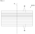
Fig. 3 is a side view of a laminated core according to an embodiment of the present invention. -
Fig. 4 is a plan view of a first surface of an electrical steel sheet in the laminated core according to the embodiment of the present invention. -
Fig. 5 is a plan view of a first surface of an electrical steel sheet in a laminated core according to an embodiment of the present invention. -
Fig. 6 is a plan view of a first surface of an electrical steel sheet in a laminated core according to a comparative example. -
Fig. 7 is a diagram showing relative values of the iron losses of laminated cores of Example 1 and Example 2 in a case in which the iron loss of the laminated core of the comparative example is set to 1. - Hereinafter, a laminated core and an electric motor according to an embodiment of the present invention will be described with reference to the drawings.
- In the present embodiment, a motor, specifically, an AC motor will be described as an example of the electric motor. The AC motor is more specifically a synchronous motor, and further more specifically a permanent magnetic electric motor. This type of motor is suitably employed for, for example, an electric vehicle and the like.
- As shown in
Figs. 1 and2 , anelectric motor 10 includes astator 20, arotor 30, acase 50, and arotary shaft 60. Thestator 20 and therotor 30 are housed in thecase 50. Thestator 20 is fixed to thecase 50. - In the present embodiment, as the
electric motor 10, an inner rotor type electric motor in which therotor 30 is located inside thestator 20 is used. However, as theelectric motor 10, an outer rotor type electric motor in which therotor 30 is located outside thestator 20 may be used. Further, in the present embodiment, theelectric motor 10 is a three-phase AC motor with twelve poles and eighteen slots. However, for example, the number of poles, the number of slots, the number of phases, and the like can be appropriately changed. - The
stator 20 includes astator core 21 and a winding (not shown). - The
stator core 21 includes an annular core backpart 22 and a plurality oftooth parts 23. The core backpart 22 is a region surrounded by an outercircumferential edge 22a of the core back part and an innercircumferential edge 22b (a broken line shown inFig. 2 ) of the core back part. Hereinafter, an axial direction of the stator core 21 (the core back part 22) (a direction of the central axis O of the stator core 21) is referred to as an axial direction. A radial direction of the stator core 21 (the core back part 22) (a direction orthogonal to the central axis O of the stator core 21) is referred to as a radial direction. A circumferential direction of the stator core 21 (the core back part 22) (a direction of rotation around the central axis O of the stator core 21) is referred to as a circumferential direction. - The core back
part 22 is formed in a circular shape in a plan view of thestator 20 in the axial direction. - The plurality of
tooth parts 23 protrude from the core backpart 22 in the radial direction (toward the central axis O of the core backpart 22 in the radial direction). The plurality oftooth parts 23 are disposed at equal intervals in the circumferential direction. In the present embodiment, eighteentooth parts 23 are provided every 20 degrees in terms of a central angle centered on the central axis O. The plurality oftooth parts 23 are formed to have the same shape and the same size. - The winding is wound around the
tooth parts 23. The winding may be a concentrated winding or a distributed winding. - The
rotor 30 is disposed inside the stator 20 (the stator core 21) in the radial direction. Therotor 30 includes arotor core 31 and a plurality ofpermanent magnets 32. - The
rotor core 31 is disposed coaxially with thestator 20 to form an annular shape (a circular shape). Therotary shaft 60 is disposed in therotor core 31. Therotary shaft 60 is fixed to therotor core 31. - The plurality of
permanent magnets 32 are fixed to therotor core 31. In the present embodiment, a set of twopermanent magnets 32 form one magnetic pole. A plurality of sets of thepermanent magnets 32 are disposed at equal intervals in the circumferential direction. In the present embodiment, twelve sets (twenty four in total) of thepermanent magnets 32 are provided every 30 degrees in terms of a central angle centered on the central axis O. - In the present embodiment, as the permanent magnetic electric motor, an interior permanent magnet motor is employed.
- In the
rotor core 31, a plurality of throughholes 33 that penetrate therotor core 31 in the axial direction are formed. The plurality of throughholes 33 are provided corresponding to the plurality ofpermanent magnets 32. Eachpermanent magnet 32 is fixed to therotor core 31 in a state of being disposed in the corresponding throughhole 33. For example, an outer surface of thepermanent magnet 32 and an inner surface of the throughhole 33 are adhered to each other by an adhesive, and thus eachpermanent magnet 32 is fixed to therotor core 31. As the permanent magnetic electric motor, a surface permanent magnet motor may be used instead of the interior permanent magnet motor. - Each of the
stator core 21 and therotor core 31 is a laminated core. The laminated core is formed by a plurality ofelectrical steel sheets 40 being stacked. - The stacking thickness of each of the
stator core 21 and therotor core 31 is, for example, 50.0 mm. The outer diameter of thestator core 21 is, for example, 250.0 mm. The inner diameter of thestator core 21 is, for example, 165.0 mm. The outer diameter of therotor core 31 is, for example, 163.0 mm. The inner diameter of therotor core 31 is, for example, 30.0 mm. However, these values are examples, and the stacking thickness, the outer diameter, and the inner diameter of thestator core 21 and the stacking thickness, the outer diameter, and the inner diameter of therotor core 31 are not limited to these values. Here, the inner diameter of thestator core 21 is based on a tip end of each of thetooth parts 23 of thestator core 21. The inner diameter of thestator core 21 is a diameter of a virtual circle inscribed in the tip ends of all of thetooth parts 23. - Each
electrical steel sheet 40 for forming thestator core 21 and therotor core 31 is formed, for example, by a process of punching an electrical steel sheet as a base material. A known electrical steel sheet can be used as theelectrical steel sheet 40. The chemical composition of theelectrical steel sheet 40 is not particularly limited. In the present embodiment, as theelectrical steel sheet 40, a non-grain-oriented electrical steel sheet is employed. As the non-grain-oriented electrical steel sheet, for example, a non-grain-oriented electrical steel strip of Japanese Industrial Standards (JIS) C 2552: 2014 can be employed. - However, as the
electrical steel sheet 40, a grain-oriented electrical steel sheet can also be employed instead of a non-grain-oriented electrical steel sheet. As the grain-oriented electrical steel sheet, a JIS C 2553: 2012 grain-oriented electrical steel strip can be employed. - An insulation coating is provided on each of both surfaces of the
electrical steel sheet 40 to improve the workability of the electrical steel sheet and to reduce the iron loss of the laminated core. As the substance constituting the insulation coating, for example, (1) an inorganic compound, (2) an organic resin, (3) a mixture of an inorganic compound and an organic resin, and the like can be applied. Examples of the inorganic compound include (1) a complex of dichromate and boric acid, (2) a complex of phosphate and silica, and the like. Examples of the organic resin include epoxy-based resins, acrylic-based resins, acrylic-styrene-based resins, polyester-based resins, silicone-based resins, fluorine-based resins, and the like. - To ensure the insulation performance between the
electrical steel sheets 40 stacked on each other, the thickness of the insulation coating (the thickness per one surface of the electrical steel sheet 40) is preferably 0.1 µm or more. - On the other hand, as the insulation coating becomes thicker, the insulation effect becomes saturated. Further, as the insulation coating becomes thicker, the space factor decreases, and a performance for serving as the laminated core deteriorates. Therefore, it is preferable to form the insulation coating as thin as possible in a range in which the insulation performance can be ensured. The thickness of the insulation coating (the thickness per one surface of the electrical steel sheet 40) is preferably 0.1 µm or more and 5 µm or less, and more preferably 0.1 µm or more and 2 µm or less.
- As the
electrical steel sheet 40 becomes thinner, the effect of reducing the iron loss gradually becomes saturated. Further, as theelectrical steel sheet 40 becomes thinner, the manufacturing cost of theelectrical steel sheet 40 increases. Therefore, in consideration of the effect of reducing the iron loss and the manufacturing cost, the thickness of theelectrical steel sheet 40 is preferably 0.10 mm or more. - On the other hand, if the
electrical steel sheet 40 is too thick, a press punching operation of theelectrical steel sheet 40 becomes difficult. - Therefore, in consideration of the press punching operation of the
electrical steel sheet 40, the thickness of theelectrical steel sheet 40 is preferably 0.65 mm or less. - Further, as the
electrical steel sheet 40 becomes thicker, the iron loss increases. Therefore, in consideration of the iron loss characteristics of theelectrical steel sheet 40, the thickness of theelectrical steel sheet 40 is preferably 0.35 mm or less. The thickness of theelectrical steel sheet 40 is more preferably 0.20 mm or 0.25 mm. - In consideration of the above points, the thickness of each
electrical steel sheet 40 is, for example, 0.10 mm or more and 0.65 mm or less. The thickness of eachelectrical steel sheet 40 is preferably 0.10 mm or more and 0.35 mm or less, and more preferably 0.20 mm or 0.25 mm. The thickness of theelectrical steel sheet 40 also includes the thickness of the insulation coating. - As shown in
Fig. 3 , the plurality ofelectrical steel sheets 40 for forming thestator core 21 are stacked in a thickness direction. The thickness direction is a thickness direction of theelectrical steel sheet 40. The thickness direction corresponds to a stacking direction of theelectrical steel sheets 40. The plurality ofelectrical steel sheets 40 are disposed coaxially with the central axis O. Theelectrical steel sheet 40 includes the core backpart 22 and the plurality oftooth parts 23. - As shown in
Fig. 4 , the plurality ofelectrical steel sheets 40 for forming thestator core 21 are fixed to each other by anadhesion part 41 andfastening parts 25 which are provided on a surface (a first surface) 40a of theelectrical steel sheet 40. - For example, although not shown, the
fastening part 25 is constituted by a convex part (a dowel) and a concave part which are formed in theelectrical steel sheet 40. The convex part protrudes from theelectrical steel sheet 40 in the stacking direction. The concave part is disposed in a portion of theelectrical steel sheet 40 which is located on a back side of the convex part. The concave part is recessed in the stacking direction with respect to the surface of theelectrical steel sheet 40. The convex part and the concave part are formed, for example, by a process of pressing theelectrical steel sheet 40. - Out of a pair of
electrical steel sheets 40 overlapping in the stacking direction, the convex part of thefastening part 25 of oneelectrical steel sheet 40 fits into the concave part of thefastening part 25 of the otherelectrical steel sheet 40. - The
adhesion part 41 adheres the core back parts 22 (the electrical steel sheets 40) adjacent in the stacking direction to each other. The plurality ofelectrical steel sheets 40 for forming thestator core 21 are adhered to each other by theadhesion part 41. - The
adhesion part 41 is an adhesive that is provided between theelectrical steel sheets 40 adjacent in the stacking direction and has cured without being divided. As the adhesive, for example, a thermosetting type adhesive by polymer bonding and the like is used. - As a composition of the adhesive, (1) an acrylic-based resin, (2) an epoxy-based resin, (3) a composition containing an acrylic-based resin and an epoxy-based resin, and the like can be applied.
- As the adhesive, in addition to the thermosetting type adhesive, a radical polymerization type adhesive and the like can also be used. From the viewpoint of productivity, a room temperature curing type (a room temperature adhesion type) adhesive is desirable. The room temperature curing type adhesive is an adhesive that cures at 20°C to 30°C. In addition, in the present specification, a value range represented using "to" means a range including values before and after "to" as a lower limit value and an upper limit value.
- As the room temperature curing type adhesive, an acrylic-based adhesive is preferable. Typical acrylic-based adhesives include a second generation acrylic-based adhesive (SGA) and the like. Any one of an anaerobic adhesive, an instant adhesive, and an elastomer-containing acrylic-based adhesive can be used as long as the effects of the present invention are not impaired.
- The adhesive referred to here refers to an adhesive in a state before curing. After the adhesive cures, it becomes the
adhesion part 41. - An average tensile modulus of elasticity E of the
adhesion parts 41 at room temperature (20°C to 30°C) is in the range of 1500 MPa to 4500 MPa. If the average tensile modulus of elasticity E of theadhesion parts 41 is less than 1500 MPa, a problem that the rigidity of the laminated core is lowered occurs. Therefore, a lower limit of the average tensile modulus of elasticity E of theadhesion parts 41 is 1500 MPa, and more preferably 1800 MPa. On the contrary, if the average tensile modulus of elasticity E of theadhesion parts 41 exceeds 4500 MPa, a problem that the insulation coating formed on the surface of theelectrical steel sheet 40 is peeled off occurs. Therefore, an upper limit of the average tensile modulus of elasticity E of theadhesion parts 41 is 4500 MPa, and more preferably 3650 MPa. - The average tensile modulus of elasticity E is measured by a resonance method. Specifically, a tensile modulus of elasticity is measured in conformity with JIS R 1602: 1995.
- More specifically, first, a sample for measurement (not shown) is made. This sample is obtained by adhering two
electrical steel sheets 40 to each other by the adhesive to be measured and curing the adhesive to form theadhesion part 41. In a case in which the adhesive is a thermosetting type adhesive, this curing is performed by heating and pressurizing under heating and pressurizing conditions in actual operation. On the other hand, in a case in which the adhesive is a room temperature curing type adhesive, the curing is performed by pressurizing at room temperature. - Then, the tensile modulus of elasticity of this sample is measured by a resonance method. As described above, a method of measuring a tensile modulus of elasticity by the resonance method is performed in conformity with JIS R 1602: 1995. After that, the tensile modulus of elasticity of the
adhesion part 41 alone is obtained by removing the influence of theelectrical steel sheet 40 itself from the tensile modulus of elasticity (the measured value) of the sample by calculation. - The tensile modulus of elasticity thus obtained from the sample is equal to an average value for the
stator core 21 as a whole, which is a laminated core. Therefore, this value is regarded as the average tensile modulus of elasticity E. The composition of the average tensile modulus of elasticity E is set such that the average tensile modulus of elasticity E is hardly changed depending on a stacking position in the stacking direction and a circumferential position around the central axis of thestator core 21. Therefore, a value obtained by measuring the tensile modulus of elasticity of the curedadhesion part 41 at an upper end position in thestator core 21 can be regarded as the average tensile modulus of elasticity E. - As an adhesion method using a thermosetting type adhesive, for example, a method of applying an adhesive to the
electrical steel sheets 40, and then adhering theelectrical steel sheets 40 to each other by either one or both of heating and press-stacking can be employed. - As a heating means, for example, a method of heating in a high temperature bath or an electric furnace, a method of directly energizing, or the like is used. The heating means may be any means.
- To obtain stable and sufficient adhesion strength, the thickness of the
adhesion part 41 is preferably 1 µm or more. On the other hand, when the thickness of theadhesion part 41 exceeds 100 µm, an adhesion force becomes saturated. Further, as theadhesion part 41 becomes thicker, the space factor decreases, and the magnetic properties of the laminated core in the iron loss and the like deteriorates. - Therefore, the thickness of the
adhesion part 41 is 1 µm or more and 100 µm or less. The thickness of theadhesion part 41 is more preferably 1 µm or more and 10 µm or less. - In the above, the thickness of the
adhesion part 41 means an average thickness of theadhesion parts 41. - The average thickness of the
adhesion parts 41 is more preferably 1.0 µm or more and 3.0 µm or less. If the average thickness of theadhesion parts 41 is less than 1.0 µm, a sufficient adhesion force cannot be secured as described above. Therefore, a lower limit of the average thickness of theadhesion parts 41 is 1.0 µm, and more preferably 1.2 µm. On the contrary, if the average thickness of theadhesion parts 41 becomes thicker than 3.0 µm, problems such as a large increase in a strain amount of theelectrical steel sheet 40 due to shrinkage during thermosetting occur. Therefore, an upper limit of the average thickness of theadhesion parts 41 is 3.0 µm, and more preferably 2.6 µm. - The average thickness of the
adhesion parts 41 is an average value for thestator core 21 as a whole. The average thickness of theadhesion parts 41 is hardly changed depending on a stacking position in the stacking direction and a circumferential position around the central axis of thestator core 21. Therefore, an average value of values obtained by measuring the thicknesses of theadhesion parts 41 at the upper end position in thestator core 21 at ten or more points in the circumferential direction can be regarded as the average thickness of theadhesion parts 41. - The average thickness of the
adhesion parts 41 can be adjusted, for example, by changing the application amount of the adhesive. Further, for example, in a case of a thermosetting type adhesive, the average tensile modulus of elasticity E of theadhesion parts 41 can be adjusted by changing either one or both of heating and pressurizing conditions applied at the time of adhesion and the type of a curing agent. - In the present embodiment, the plurality of
electrical steel sheets 40 for forming therotor core 31 are fixed to each other by a fastening part 42 (a dowel, seeFig. 1 ). - However, the plurality of
electrical steel sheets 40 for forming therotor core 31 may be adhered to each other by theadhesion part 41. - The laminated core such as the
stator core 21 and therotor core 31 may be formed by so-called the turn-stacking. - As shown in
Fig. 4 , a plurality of thefastening parts 25 are provided in the core backpart 22 of theelectrical steel sheet 40 at intervals in the circumferential direction. As will be described later, the plurality offastening parts 25 are each provided on anon-adhesion region 43. The plurality offastening parts 25 are disposed on the same circle centered on the central axis O. Eachfastening part 25 is shifted with respect to each of thetooth parts 23 in the circumferential direction. - On a surface of the
electrical steel sheet 40 which faces in the stacking direction (hereinafter referred to as a first surface of the electrical steel sheet 40) 40a, anadhesion region 42 of theelectrical steel sheet 40 in which theadhesion part 41 is provided and thenon-adhesion region 43 of theelectrical steel sheet 40 in which theadhesion part 41 is not provided are formed. More specifically, theadhesion region 42 of theelectrical steel sheet 40 in which theadhesion part 41 is provided means a region of thefirst surface 40a of theelectrical steel sheet 40 in which the adhesive (the adhesion part 41) that has cured without being divided is provided. Further, thenon-adhesion region 43 of theelectrical steel sheet 40 in which theadhesion part 41 is not provided means a region of thefirst surface 40a of theelectrical steel sheet 40 in which the adhesive that has cured without being divided is not provided. - The
adhesion region 42 and thenon-adhesion region 43 are different regions from each other and do not overlap each other. - In the present embodiment, the
adhesion region 42 is formed on an outer circumferential side of the core backpart 22 of thefirst surface 40a of theelectrical steel sheet 40. In other words, theadhesion part 41 is provided on the outer circumferential side of the core backpart 22 of thefirst surface 40a of theelectrical steel sheet 40. Further, in other words, the adhesive is applied to the outer circumferential side of the core backpart 22 of thefirst surface 40a of theelectrical steel sheet 40. - The outer circumferential side of the core back
part 22 is preferably an outside of outercircumferential edges 25a of the fastening parts 25 (the outercircumferential edges 25a of thefastening parts 25 mean portions of thefastening parts 25 which are located on the outermost side of thefastening parts 25 in the radial direction). - Further, the outer circumferential side of the core back
parts 22 is more preferably an outside of avirtual circle 27 formed on an outer circumferential side of the outercircumferential edges 25a of thefastening parts 25. Thevirtual circle 27 can have the same diameter as a virtual circumscribed circle that is circumscribed about the plurality offastening parts 25. - In
Fig. 4 , theadhesion part 41 is continuously provided over the entire circumference of an outer edge of the core backpart 22 on the outside of thevirtual circle 27 formed on the outer circumferential side of the outercircumferential edges 25a of thefastening parts 25. - In other words, in
Fig. 4 , theadhesion region 42 is continuously formed over the entire circumference of an outer edge of the core backpart 22 on the outside of thevirtual circle 27 formed on the outer circumferential side of the outercircumferential edges 25a of thefastening parts 25. - As shown in
Fig. 4 , theadhesion part 41 is not provided on an inner circumferential side of the core backpart 22 of thefirst surface 40a of theelectrical steel sheet 40. In other words, the adhesive is not applied to the inner circumferential side of the core backpart 22 of thefirst surface 40a of theelectrical steel sheet 40. Further, in other words, thenon-adhesion region 43 is formed on the inner circumferential side of the core backpart 22 of thefirst surface 40a of theelectrical steel sheet 40. The plurality offastening parts 25 are provided in thenon-adhesion region 43 at intervals in the circumferential direction. - Further, the inner circumferential side of the core back
part 22 is preferably an inside of the outercircumferential edges 25a of thefastening parts 25. Further, the inner circumferential side of the core backpart 22 is more preferably an inside of avirtual circle 27 formed on an outer circumferential side of the outercircumferential edges 25a of thefastening parts 25. In other words, a portion of the core backpart 22 which is located inside the circumscribed circle in the radial direction is preferably thenon-adhesion region 43. InFig. 4 , thenon-adhesion region 43 is provided over the entire inside region of thevirtual circle 27 formed on the outer circumferential side of the outercircumferential edges 25a of thefastening parts 25 in the core backpart 22. - The
non-adhesion region 43 is also provided in a portion of thefirst surface 40a of theelectrical steel sheet 40 corresponding to each of the plurality oftooth parts 23. - The outside of the outer
circumferential edges 25a of thefastening parts 25 refers to a region of the core backpart 22 outside the outercircumferential edges 25a of thefastening parts 25. The inside of the outercircumferential edges 25a of thefastening parts 25 refers to a region of the core backpart 22 inside the outercircumferential edges 25a of thefastening parts 25 and a region of the core backpart 22 along the outercircumferential edges 25a of thefastening parts 25. Similarly, the outside of thevirtual circle 27 refers to a region of the core backpart 22 outside thevirtual circle 27. Similarly, the inside of thevirtual circle 27 refers to a region of the core backpart 22 inside thevirtual circle 27 and a region of the core backpart 22 along thevirtual circle 27. - It is assumed that the
adhesion part 41 is provided between all of the sets of theelectrical steel sheets 40 adjacent in the stacking direction as shown inFig. 4 . In this case, the ratio of an area of theadhesion region 42 to 100% of an area of the core backpart 22 of thefirst surface 40a of theelectrical steel sheet 40 is, for example, 20%. - Further, as shown in
Fig. 5 , theadhesion parts 41 may be provided on the outer circumferential side of the core backpart 22 of thefirst surface 40a of theelectrical steel sheet 40 and at least in the vicinity of thefastening parts 25 of the outer edge of the core backpart 22. The term "the vicinity of thefastening parts 25" as used herein means, for example, a range of three times the length of each of thefastening parts 25 in the circumferential direction with each of thefastening parts 25 as the center in the circumferential direction. - In an example shown in
Fig. 5 , theadhesion parts 41 are intermittently provided over the entire circumference. Theadhesion parts 41 are provided only in the vicinity of thefastening parts 25 in the outer edge of the core backpart 22. In other words, theadhesion parts 41 are also shifted with respect to thetooth parts 23 in the circumferential direction, as in thefastening parts 25. Theadhesion parts 41 are not provided in portions of the outer edge of the core backpart 22 which are located on an outside of thetooth parts 23 in the radial direction. In other words, instead of theadhesion regions 42, thenon-adhesion regions 43 are formed in portions of the outer edge of the core backpart 22 which are located on an outside of thetooth parts 23 in the radial direction. - The size of each of the
adhesion regions 42 in the circumferential direction is larger than the size of each of thefastening parts 25 in the circumferential direction. Each of thefastening parts 25 is disposed in a central portion of each of theadhesion regions 42 in the circumferential direction. The size of each of theadhesion regions 42 in the circumferential direction is larger than the interval between theadhesion regions 42 adjacent in the circumferential direction. - A case in which the
adhesion parts 41 are provided between all of the sets of theelectrical steel sheets 40 adjacent in the stacking direction as shown inFig. 5 will be described. In this case, the ratio of an area of theadhesion regions 42 to 100% of an area of the core backpart 22 of thefirst surface 40a of theelectrical steel sheet 40 is, for example, 12%. - In the present embodiment, it is assumed that the
non-adhesion regions 43 are formed in the plurality oftooth parts 23 included in theelectrical steel sheet 40. In this case, the plurality offastening parts 25 may be provided in thenon-adhesion region 43 of the core backpart 22 and thenon-adhesion regions 43 of the plurality oftooth parts 23 at intervals in the circumferential direction. - In general, an adhesive shrinks during curing. Therefore, when the adhesive is provided in the electrical steel sheet, a compressive stress is applied to the electrical steel sheet as the adhesive cures. When a compressive stress is applied, a strain occurs in the electrical steel sheet. Further, when the fastening parts are provided on the electrical steel sheet, the electrical steel sheet is deformed, and thus a strain occurs in the electrical steel sheet. The fastening parts and the adhesion region form a fixing part. The fixing part fixes the electrical steel sheets adjacent in the stacking direction to each other. As the area of the fixing part increases, the strain of the electrical steel sheet increases.
- As described above, in the stator core 21 (the laminated core) according to the present embodiment, the plurality of
fastening parts 25 are provided in the core backpart 22 at intervals in the circumferential direction. Theadhesion parts 41 are provided on the outer circumferential side of the core backpart 22 of thefirst surface 40a of theelectrical steel sheet 40. Theadhesion parts 41 are not provided on the inner circumferential side of the core backpart 22 of thefirst surface 40a of theelectrical steel sheet 40. - In other words, in the stator core 21 (the laminated core) according to the present embodiment, the plurality of
fastening parts 25 are provided in the core backpart 22 at intervals in the circumferential direction. Theadhesion regions 42 are formed on the outer circumferential side of the core backpart 22 of thefirst surface 40a of theelectrical steel sheet 40. Thenon-adhesion regions 43 are formed on the inner circumferential side of the core backpart 22 of thefirst surface 40a of theelectrical steel sheet 40. - With this configuration, the
adhesion regions 42 in which theadhesion parts 41 are provided are formed on only the outer circumferential side of the core backpart 22. The core backparts 22 of theelectrical steel sheets 40 adjacent in the stacking direction are partially adhered to each other. Therefore, the area of the adhesion regions formed in the core backpart 22 is reduced as compared with, for example, a case in which the adhesion regions extend inward in the radial direction to the fastening part. Therefore, the area of the fixing part in a plan view in the stacking direction is reduced. Accordingly, the strain that occurs in theentire stator core 21 can be made smaller. As a result, the iron loss that is generated in thestator core 21 can be reduced, and the magnetic properties of thestator core 21 can be improved. - The
fastening parts 25 are provided in thenon-adhesion regions 43 different from theadhesion regions 42. - If it is attempted to manufacture a stator core in which the fastening parts are provided in the adhesion regions, the following problems occur. For example, to provide the fastening parts in the adhesion regions, an adhesive is applied to the convex parts of the fastening parts of the electrical steel sheet. If it is attempted to fit the convex parts coated with the adhesive into the concave parts of the fastening parts of another electrical steel sheet, the adhesive gets in between the convex parts and the concave parts, and the convex parts may not fit deep into the concave part. In this case, there is a problem that the convex parts and the concave parts do not fit accurately and the pair of electrical steel sheets are not stacked in parallel to each other.
- A similar problem occurs also in a case in which the adhesive is applied to the concave parts of the fastening parts of the electrical steel sheet.
- On the other hand, in the
stator core 21 of the present embodiment, thefastening parts 25 are provided in thenon-adhesion regions 43. Therefore, the adhesive does not get in between the convex parts and the concave parts, and even if thefastening parts 25 are provided on theelectrical steel sheet 40, theelectrical steel sheets 40 adjacent in the stacking direction can be stacked in parallel to each other. - In the
stator core 21 of the present embodiment, theadhesion regions 42 are formed on the outer circumferential side of the core backpart 22. Therefore, in addition to a method in which the adhesive is applied to thefirst surface 40a of theelectrical steel sheet 40 to provide theadhesion parts 41, it is possible to provide the adhesion parts by the following method. - That is, the adhesive is disposed outside the plurality of stacked
electrical steel sheets 40 in the radial direction. When the pressure of the air inside the plurality ofelectrical steel sheets 40 in the radial direction is reduced, the adhesive is impregnated between the plurality ofelectrical steel sheets 40. It is possible to provide the adhesion parts by curing this adhesive. - In the stator core 21 (the laminated core) according to the present embodiment, the outer circumferential side of the
fastening parts 25 in the core backpart 22 is set to the outside of the outercircumferential edges 25a of thefastening parts 25. Then, the inner circumferential side of thefastening parts 25 in the core backpart 22 is set to the inside of the outercircumferential edges 25a of thefastening parts 25. - With this configuration, a portion of the
adhesion regions 42 nearest the inner circumference does not overlap with thefastening parts 25 at all. Therefore, it is possible to avoid further application of a strain due to the fixation of theadhesion part 41 being provided in the region where the strain occurs in theelectrical steel sheet 40 by fixing the stacking direction with thefastening parts 25. Therefore, the area of the fixing part is further reduced. Accordingly, the strain that occurs in theentire stator core 21 can be made smaller. - In the stator core 21 (the laminated core) according to the present embodiment, the outer circumferential side of the core back
part 22 is set to the outside of thevirtual circle 27 formed on the outer circumferential side of the outercircumferential edges 25a of thefastening parts 25. Then, the inner circumferential side of the core backpart 22 is set to the inside of thevirtual circle 27 formed on the outer circumferential side of the outercircumferential edges 25a of thefastening parts 25. - With this configuration, the
adhesion regions 42 are not provided in thetooth parts 23. Therefore, the area of the fixing part that fixes theelectrical steel sheets 40 adjacent in the stacking direction and is constituted by thefastening parts 25 and the adhesion parts 41 (the adhesion regions 42) is further reduced. Accordingly, the strain that occurs in theentire stator core 21 can be made smaller. - In the stator core 21 (the laminated core) according to the present embodiment, the
adhesion parts 41 are provided at least in the vicinity of thefastening parts 25 in the outer edge of the core backpart 22. - Accordingly, the
adhesion parts 41 are provided discontinuously (intermittently) at intervals without being continuously provided over the entire circumference of the outer edge of the core backpart 22. Therefore, the area of theadhesion regions 42 formed in the core backpart 22 is reduced as compared with, for example, a case in which the adhesion regions are formed over the entire circumference of the core back part. Accordingly, the area of the fixing part is further reduced. Therefore, the strain that occurs in theentire stator core 21 can be made smaller. - The stator core 21 (the laminated core) according to the present embodiment includes the
adhesion parts 41 provided in theadhesion regions 42 of the core backpart 22. Therefore, it is possible to reliably adhere theelectrical steel sheets 40 adjacent in the stacking direction to each other using theadhesion parts 41. - In the stator core 21 (the laminated core) according to the present embodiment, the
electrical steel sheet 40 includes the plurality oftooth parts 23 in which thenon-adhesion regions 43 are formed. Accordingly, the area of thenon-adhesion regions 43 in theelectrical steel sheet 40 increases. Therefore, it is possible to increase a region where a strain does not occur in thestator core 21. - The
electric motor 10 according to the present embodiment includes the stator core 21 (the laminated core) according to the present embodiment. Therefore, it is possible to improve the magnetic properties of theelectric motor 10. - The technical scope of the present invention is not limited to the above-described embodiments, and various modifications can be made without departing from the gist of the present invention.
- The shape of the stator core is not limited to the forms shown in the above-described embodiments. Specifically, the dimensions of the outer diameter and the inner diameter of the stator core, the stacking thickness, the number of the slots, the dimensional ratio of each of the tooth parts in the circumferential direction and the radial direction, the dimensional ratio between each of the tooth parts and the core back part in the radial direction, and the like can be arbitrarily designed according to the properties of the desired electric motor.
- In the rotor of the above-described embodiments, a set of two
permanent magnets 32 form one magnetic pole, but the present invention is not limited to this. For example, onepermanent magnet 32 may form one magnetic pole, or three or morepermanent magnets 32 may form one magnetic pole. - In the above-described embodiments, the permanent magnetic electric motor has been described as an example of the electric motor, but the structure of the electric motor is not limited to this as will be illustrated below. As the structure of the electric motor, various known structures that will not be illustrated below can also be employed.
- In the above-described embodiments, the permanent magnetic electric motor has been described as an example of the synchronous motor. However, the present invention is not limited to this. For example, the electric motor may be a reluctance motor or an electromagnet field motor (a wound-field motor).
- In the above-described embodiments, the synchronous motor has been described as an example of the AC motor. However, the present invention is not limited to this. For example, the electric motor may be an induction motor.
- In the above-described embodiments, the AC motor has been described as an example of the motor. However, the present invention is not limited to this. For example, the electric motor may be a DC motor.
- In the above-described embodiments, the motor has been described as an example of the electric motor. However, the present invention is not limited to this. For example, the electric motor may be an electric generator.
- In the above-described embodiments, the case in which the laminated core according to the present invention is applied to the stator core has been illustrated. The laminated core according to the present invention can also be applied to the rotor core.
- In addition, it is possible to appropriately replace the configuration elements in the above-described embodiments with well-known configuration elements without departing from the gist of the present invention. Further, the above-described modification examples may be appropriately combined.
- Hereinafter, the present invention will be described more specifically with examples and a comparative example, but the present invention is not limited to the following examples.
- As shown in
Fig. 4 , theadhesion part 41 was provided on the outer circumferential side of the core backpart 22 of thefirst surface 40a of theelectrical steel sheet 40. The plurality ofelectrical steel sheets 40 configured in this way were stacked to form the laminated core. - The ratio of an area of the
adhesion region 42 to 100% of an area of the core backpart 22 of thefirst surface 40a of theelectrical steel sheet 40 was 20%. - Two types of laminated cores having different sheet thicknesses of the
electrical steel sheet 40 were formed using theelectrical steel sheet 40 having a sheet thickness of 0.20 mm and theelectrical steel sheet 40 having a sheet thickness of 0.25 mm. - As shown in
Fig. 5 , theadhesion parts 41 were provided on the outer circumferential side of the core backpart 22 of thefirst surface 40a of theelectrical steel sheet 40 and at least in the vicinity of thefastening parts 25 of the outer edge of the core backpart 22. The plurality ofelectrical steel sheets 40 configured in this way were stacked to form the laminated core. - The ratio of an area of the
adhesion regions 42 to 100% of an area of the core backpart 22 of thefirst surface 40a of theelectrical steel sheet 40 was 12%. - In other points, as in Example 1, two types of laminated cores having different sheet thicknesses of the
electrical steel sheet 40 were formed. - As shown in
Fig. 6 , theadhesion part 41 was provided over a region from aboundary 22c between the core backpart 22 and the outercircumferential edge 22a of thefirst surface 40a of theelectrical steel sheet 40 to the inner circumferential side of the core backpart 22 of thefirst surface 40a of theelectrical steel sheet 40. The plurality ofelectrical steel sheets 40 configured in this way were stacked to form the laminated core. - The ratio of an area of the
adhesion region 42 to 100% of an area of the core backpart 22 of thefirst surface 40a of theelectrical steel sheet 40 was 80%. - In other points, as in Example 1, two types of laminated cores having different sheet thicknesses of the
electrical steel sheet 40 were manufactured. - In the laminated cores produced in Examples 1 and 2 and the comparative example, an excitation current having an effective value of 10 A and a frequency of 100 Hz was applied to the winding of each phase. Then, the iron loss was evaluated under the condition that the rotation speed of the rotor was set to 1000 rpm.
- The evaluation of the iron loss was executed by a simulation using software. As the software, electromagnetic field simulation software JMAG which is based on a finite element method and is manufactured by JSOL Corporation was used.
- Relative values of the iron losses of laminated cores of Examples 1 and 2 with the iron loss of the laminated core of the comparative example set to 1 are shown in
Fig. 7 . - From the results of
Fig. 7 , it was found that the iron losses of the laminated cores of Examples 1 and 2 are lower than that of the laminated core of the comparative example regardless of the thickness of theelectrical steel sheet 40. - Therefore, it was found that in the laminated cores of Examples 1 and 2, it is possible to reduce the loss generated in the laminated core by reducing the strain occurred in the entire laminated core. Further, it was found that in the laminated cores of Examples 1 and 2, it is possible to sufficiently secure the magnetic properties of the laminated core.
- According to the present invention, it is possible to provide a laminated core having improved magnetic properties and an electric motor including the laminated core. Therefore, the industrial applicability is great.
-
- 10
- Electric motor
- 20
- Stator
- 21
- Stator core (laminated core)
- 22
- Core back part
- 23
- Tooth part
- 25
- fastening part
- 27
- Virtual circle
- 30
- Rotor
- 31
- Rotor core (laminated core)
- 32
- Permanent magnet
- 33
- Through hole
- 40
- Electrical steel sheet
- 41
- Adhesion part
- 42
- Adhesion region
- 43
- Non-adhesion region
- 50
- Case
- 60
- Rotary shaft
Claims (9)
- A laminated core comprising a plurality of electrical steel sheets stacked in a thickness direction, wherein:each of the electrical steel sheets includes an annular core back part;an adhesion region is formed on an outer circumferential side of the core back part;a non-adhesion region is formed on an inner circumferential side of the core back part; anda plurality of fastening parts are provided in the non-adhesion region of the core back part at intervals in a circumferential direction.
- The laminated core according to claim 1, wherein:the outer circumferential side of the core back part is an outside of outer circumferential edges of the fastening parts; andthe inner circumferential side of the core back part is an inside of the outer circumferential edges of the fastening parts.
- The laminated core according to claim 2, wherein:the outer circumferential side of the core back parts is an outside of a virtual circle formed on an outer circumferential side of the outer circumferential edges of the fastening parts; andthe inner circumferential side of the core back part is an inside of the virtual circle.
- The laminated core according to any one of claims 1 to 3, wherein the adhesion regions are formed at least in the vicinity of the fastening parts in the outer circumferential edge of the core back part.
- The laminated core according to any one of claims 1 to 4, further comprising an adhesion part which is provided in the adhesion region of the core back part between the electrical steel sheets adjacent in the stacking direction and adheres the core back parts adjacent in the stacking direction to each other.
- The laminated core according to claim 5, wherein an average thickness of the adhesion parts is 1.0 µm to 3.0 µm.
- The laminated core according to claim 5 or 6, wherein an average tensile modulus of elasticity E of the adhesion parts is 1500 MPa to 4500 MPa.
- The laminated core according to any one of claims 5 to 7, wherein the adhesion part is a room temperature adhesion type acrylic-based adhesive including SGA made of an elastomer-containing acrylic-based adhesive.
- An electric motor comprising the laminated core according to any one of claims 1 to 8.
Applications Claiming Priority (2)
| Application Number | Priority Date | Filing Date | Title |
|---|---|---|---|
| JP2018235861 | 2018-12-17 | ||
| PCT/JP2019/049282 WO2020129935A1 (en) | 2018-12-17 | 2019-12-17 | Laminated core and rotating machine |
Publications (2)
| Publication Number | Publication Date |
|---|---|
| EP3902109A1 true EP3902109A1 (en) | 2021-10-27 |
| EP3902109A4 EP3902109A4 (en) | 2022-10-05 |
Family
ID=71100299
Family Applications (1)
| Application Number | Title | Priority Date | Filing Date |
|---|---|---|---|
| EP19899146.5A Pending EP3902109A4 (en) | 2018-12-17 | 2019-12-17 | LAMINATED CORE AND ROTARY MACHINE |
Country Status (11)
| Country | Link |
|---|---|
| US (1) | US11979059B2 (en) |
| EP (1) | EP3902109A4 (en) |
| JP (1) | JP7576981B2 (en) |
| KR (1) | KR102607589B1 (en) |
| CN (1) | CN113196618B (en) |
| CA (1) | CA3131664A1 (en) |
| EA (1) | EA202192071A1 (en) |
| MY (1) | MY208525A (en) |
| SG (1) | SG11202108948YA (en) |
| TW (1) | TWI724690B (en) |
| WO (1) | WO2020129935A1 (en) |
Families Citing this family (19)
| Publication number | Priority date | Publication date | Assignee | Title |
|---|---|---|---|---|
| EP3902123B1 (en) | 2018-12-17 | 2025-10-29 | Nippon Steel Corporation | Laminated core, laminated core manufacturing method, and electric motor |
| CA3131673C (en) | 2018-12-17 | 2024-02-20 | Nippon Steel Corporation | Laminated core, method of manufacturing same, and electric motor |
| MY207178A (en) | 2018-12-17 | 2025-02-04 | Nippon Steel Corp | Laminated core and electric motor |
| CN113169594B (en) | 2018-12-17 | 2025-08-12 | 日本制铁株式会社 | Laminated iron core and rotating electrical machine |
| EP3902120A4 (en) | 2018-12-17 | 2022-10-05 | Nippon Steel Corporation | STACKED CORE AND ROTATING ELECTRIC MACHINE |
| US11990795B2 (en) | 2018-12-17 | 2024-05-21 | Nippon Steel Corporation | Adhesively-laminated core for stator, method of manufacturing same, and electric motor |
| EA202192072A1 (en) | 2018-12-17 | 2021-11-09 | Ниппон Стил Корпорейшн | CORE AND ELECTRIC MOTOR |
| CA3131358A1 (en) | 2018-12-17 | 2020-06-25 | Nippon Steel Corporation | Laminated core, core block, electric motor and method of producing core block |
| WO2020129937A1 (en) | 2018-12-17 | 2020-06-25 | 日本製鉄株式会社 | Laminated core and rotating electric machine |
| EP3902104A4 (en) | 2018-12-17 | 2022-10-05 | Nippon Steel Corporation | LAMINATE CORE AND ROTATING ELECTRIC MACHINE |
| RS67409B1 (en) | 2018-12-17 | 2025-12-31 | Nippon Steel Corp | Adhesively laminated core for stator and electrical motor |
| MY204004A (en) | 2018-12-17 | 2024-07-31 | Nippon Steel Corp | Adhesively-laminated core, manufacturing method thereof, and electric motor |
| PL3902105T3 (en) | 2018-12-17 | 2024-12-02 | Nippon Steel Corporation | Laminated core and rotating electric machine |
| TWI744743B (en) | 2018-12-17 | 2021-11-01 | 日商日本製鐵股份有限公司 | Laminated iron core and rotating electric machine |
| EA202192059A1 (en) | 2018-12-17 | 2021-12-31 | Ниппон Стил Корпорейшн | GLUE-SLATED CORE FOR STATOR AND ELECTRIC MOTOR |
| JP7515403B2 (en) | 2018-12-17 | 2024-07-12 | 日本製鉄株式会社 | Adhesive laminated core for stator, manufacturing method thereof, and rotating electric machine |
| DE202022103747U1 (en) | 2021-07-12 | 2022-10-17 | Hyundai Mobis Co., Ltd. | LED modules |
| TWI853479B (en) * | 2022-03-08 | 2024-08-21 | 日商日本製鐵股份有限公司 | Laminated iron core, rotor and manufacturing method of laminated iron core |
| CN115632528B (en) | 2022-12-21 | 2023-03-28 | 苏州范斯特机械科技有限公司 | Production equipment and production method of motor laminated iron core |
Family Cites Families (190)
| Publication number | Priority date | Publication date | Assignee | Title |
|---|---|---|---|---|
| US3386058A (en) | 1966-11-21 | 1968-05-28 | Westinghouse Electric Corp | Inductive assembly with supporting means |
| US4025379A (en) | 1973-05-03 | 1977-05-24 | Whetstone Clayton N | Method of making laminated magnetic material |
| US4103195A (en) | 1976-08-11 | 1978-07-25 | General Electric Company | Bonded laminations forming a stator core |
| JPS5665326A (en) | 1979-10-29 | 1981-06-03 | Tdk Corp | Magnetic core for magnetic head |
| JPS576427A (en) | 1980-06-11 | 1982-01-13 | Canon Inc | Manufacture of magnetic core |
| US4413406A (en) | 1981-03-19 | 1983-11-08 | General Electric Company | Processing amorphous metal into packets by bonding with low melting point material |
| JPS60170681A (en) | 1984-02-16 | 1985-09-04 | Nippon Synthetic Chem Ind Co Ltd:The | adhesive composition |
| JPS60186834A (en) | 1984-03-07 | 1985-09-24 | Toray Ind Inc | Photosensitive resin plate material developable with water |
| JPS60186834U (en) | 1984-05-18 | 1985-12-11 | 株式会社東芝 | Stator core of rotating electric machine |
| JPS63207639A (en) | 1987-02-25 | 1988-08-29 | 日新製鋼株式会社 | Vibration-damping steel plate and manufacture thereof |
| JPH03124247A (en) * | 1989-10-05 | 1991-05-27 | Aichi Emerson Electric Co Ltd | Stator for rotary electric machine |
| JPH03247683A (en) | 1990-02-23 | 1991-11-05 | Sumitomo Chem Co Ltd | Acrylic adhesive composition |
| JPH0428743U (en) | 1990-05-22 | 1992-03-06 | ||
| JP2897344B2 (en) | 1990-05-23 | 1999-05-31 | 住友化学工業株式会社 | Thermoplastic resin composition |
| JPH08996B2 (en) | 1991-01-24 | 1996-01-10 | 新日本製鐵株式会社 | Method for manufacturing surface-treated steel sheet with excellent weldability and paint adhesion |
| US5448119A (en) | 1991-03-29 | 1995-09-05 | Nagano Nidec Corporation | Spindle motor |
| US5142178A (en) | 1991-04-12 | 1992-08-25 | Emerson Electric Co. | Apparatus for aligning stacked laminations of a dynamoelectric machine |
| JPH0614481A (en) | 1992-06-25 | 1994-01-21 | Mitsubishi Electric Corp | Armature iron core |
| JPH07118620A (en) | 1993-10-22 | 1995-05-09 | Nippon Zeon Co Ltd | Epoxy adhesive composition |
| JPH07298567A (en) | 1994-04-26 | 1995-11-10 | Honda Motor Co Ltd | Heater for bonding laminated steel sheets |
| JPH08259899A (en) | 1995-03-23 | 1996-10-08 | Three Bond Co Ltd | Cyanoacrylate adhesive composition |
| JP3124247B2 (en) | 1997-06-27 | 2001-01-15 | アロカ株式会社 | Ultrasound Doppler diagnostic device |
| JP3369941B2 (en) | 1997-11-27 | 2003-01-20 | 日本鋼管株式会社 | Manufacturing method of electrical steel sheet for bonded iron core with excellent adhesive strength, corrosion resistance and blocking resistance |
| JP2000050539A (en) | 1998-07-28 | 2000-02-18 | Toshiba Corp | Stator core of rotating electric machine, steel plate part for stator core, method of manufacturing stator core, and method of manufacturing steel plate part for stator core |
| JP2000152570A (en) | 1998-11-06 | 2000-05-30 | Toshiba Corp | Manufacturing method of magnet core |
| JP2001115125A (en) | 1999-10-01 | 2001-04-24 | Three M Innovative Properties Co | Adhesive for neodymium magnet, and motor |
| FR2803126B1 (en) | 1999-12-23 | 2006-04-14 | Valeo Equip Electr Moteur | ALTERNATOR FOR STATOR VEHICLE WITH LITTLE NOISE OF MAGNETIC NOISE |
| JP2001251828A (en) | 2000-03-02 | 2001-09-14 | Moric Co Ltd | Multipole magnet generator for internal combustion engine |
| JP2002078257A (en) | 2000-08-24 | 2002-03-15 | Mitsubishi Electric Corp | Motor and its rotor |
| JP3730218B2 (en) | 2000-08-29 | 2005-12-21 | 三菱電機株式会社 | Stacked stator core and manufacturing method thereof, and rotary motor and manufacturing method thereof |
| JP2002164224A (en) | 2000-08-30 | 2002-06-07 | Mitsui Chemicals Inc | Magnetic substrate and method of manufacturing the same |
| JP4020236B2 (en) | 2000-09-18 | 2007-12-12 | 電気化学工業株式会社 | Curable resin composition, cured body, adhesive composition, and joined body |
| JP2002105283A (en) | 2000-09-28 | 2002-04-10 | Nhk Spring Co Ltd | Epoxy resin dispersion, copper-clad laminate and copper-clad metal substrate using the same |
| JP2002125341A (en) | 2000-10-16 | 2002-04-26 | Denki Kagaku Kogyo Kk | Stator and motor using the same |
| JP2002151335A (en) | 2000-11-10 | 2002-05-24 | Nippon Steel Corp | Laminated iron core excellent in iron loss characteristics and method of manufacturing the same |
| JP3725776B2 (en) | 2000-11-10 | 2005-12-14 | 新日本製鐵株式会社 | Method for manufacturing laminated iron core and apparatus for manufacturing the same |
| EP1241773B1 (en) | 2001-03-14 | 2012-09-12 | Nissan Motor Co., Ltd. | Rotating electrical machine with air-gap sleeve |
| JP4076323B2 (en) | 2001-05-08 | 2008-04-16 | 電気化学工業株式会社 | Curable resin composition, cured body, adhesive composition, and joined body |
| JP4018885B2 (en) | 2001-05-25 | 2007-12-05 | 株式会社三井ハイテック | Laminated iron core |
| JP3594003B2 (en) | 2001-08-28 | 2004-11-24 | 日産自動車株式会社 | Rotating electric machine and method of manufacturing the same |
| JP3899885B2 (en) * | 2001-10-05 | 2007-03-28 | 株式会社日立製作所 | Permanent magnet rotating electric machine |
| JP2003199303A (en) | 2001-12-27 | 2003-07-11 | Matsushita Electric Ind Co Ltd | Motor manufacturing method |
| JP4165072B2 (en) | 2002-01-15 | 2008-10-15 | 日立化成工業株式会社 | Adhesive composition, adhesive film, wiring board for semiconductor mounting, semiconductor device and manufacturing method thereof |
| JP2003219585A (en) | 2002-01-22 | 2003-07-31 | Mitsubishi Electric Corp | Laminated core and method of manufacturing the same |
| JP2003259574A (en) * | 2002-03-05 | 2003-09-12 | Asmo Co Ltd | Core, armature and motor |
| JP3771933B2 (en) | 2002-03-08 | 2006-05-10 | Jfeスチール株式会社 | LAMINATED CORE MATERIAL AND METHOD FOR PRODUCING THE SAME |
| JP2003284274A (en) | 2002-03-22 | 2003-10-03 | Nippon Steel Corp | Permanent magnet synchronous motor rotor |
| JP2003324869A (en) * | 2002-05-08 | 2003-11-14 | Daikin Ind Ltd | Electric motor and compressor |
| JP2004088970A (en) | 2002-08-29 | 2004-03-18 | Hitachi Ltd | Laminated core, rotating electric machine and transformer using the same |
| JP2004111509A (en) | 2002-09-17 | 2004-04-08 | Nippon Steel Corp | Laminated iron core excellent in iron loss characteristics and method of manufacturing the same |
| JP4222000B2 (en) | 2002-10-29 | 2009-02-12 | Nok株式会社 | Magnetic encoder |
| JP3791492B2 (en) | 2002-12-25 | 2006-06-28 | 株式会社日立製作所 | Rotating electric machine, electric vehicle, and resin insert molding method |
| JP4143090B2 (en) | 2003-02-03 | 2008-09-03 | 新日本製鐵株式会社 | Surface coated electrical steel sheet for bonding |
| JP4987216B2 (en) | 2003-06-25 | 2012-07-25 | Jfeスチール株式会社 | Laminated core with excellent dimensional accuracy and manufacturing method thereof |
| US7362031B2 (en) | 2003-09-03 | 2008-04-22 | Mitsuba Corporation | Electric motor |
| JP2005269732A (en) | 2004-03-17 | 2005-09-29 | Nippon Steel Corp | Iron core manufacturing method and apparatus suitable for the method |
| JP2005268589A (en) | 2004-03-19 | 2005-09-29 | Nippon Steel Corp | Simple manufacturing method of magnetic member for energy conversion equipment |
| JP4548049B2 (en) | 2004-09-01 | 2010-09-22 | 株式会社日立製作所 | Rotating electric machine |
| JP4498154B2 (en) | 2005-01-27 | 2010-07-07 | ファナック株式会社 | Motor manufacturing method and motor manufacturing apparatus |
| JP2006254530A (en) | 2005-03-08 | 2006-09-21 | Mitsubishi Electric Corp | Electric motor |
| JP2006288114A (en) | 2005-04-01 | 2006-10-19 | Mitsui High Tec Inc | Laminated iron core and method for producing laminated iron core |
| JP2006353001A (en) | 2005-06-15 | 2006-12-28 | Japan Servo Co Ltd | Laminated iron core and method and apparatus for manufacturing the same |
| JP4687289B2 (en) | 2005-07-08 | 2011-05-25 | 東洋紡績株式会社 | Polyamide-based mixed resin laminated film roll and manufacturing method thereof |
| JP4586669B2 (en) | 2005-08-01 | 2010-11-24 | 住友金属工業株式会社 | Method for producing non-oriented electrical steel sheet for rotor |
| JP2007053896A (en) | 2005-08-17 | 2007-03-01 | Minebea Co Ltd | Stator unit and manufacturing method thereof |
| JP4236056B2 (en) | 2006-02-08 | 2009-03-11 | 三菱電機株式会社 | Magnet generator |
| KR100808194B1 (en) | 2006-05-19 | 2008-02-29 | 엘지전자 주식회사 | Stator of outer rotor type motor |
| JP4938389B2 (en) | 2006-09-06 | 2012-05-23 | 三菱電機株式会社 | Laminated core and stator |
| WO2008044740A1 (en) | 2006-10-13 | 2008-04-17 | Mitsui High-Tec, Inc. | Laminated iron core, and its manufacturing method |
| ITMI20070508A1 (en) | 2007-03-14 | 2008-09-15 | Corrada Spa | LAMINAR ARTICLE FOR ELECTRICAL USE PROCEDURE AND MACHINES TO REALIZE THE LAMINAR ARTICLE |
| JP5129810B2 (en) | 2007-05-09 | 2013-01-30 | 株式会社三井ハイテック | Laminated iron core and method for manufacturing the same |
| KR100988184B1 (en) | 2007-07-19 | 2010-10-18 | 세키스이가가쿠 고교가부시키가이샤 | Adhesive for electronic component |
| JP2009072035A (en) | 2007-09-18 | 2009-04-02 | Meidensha Corp | Rotor core of rotating electrical machine |
| JP5211651B2 (en) | 2007-11-15 | 2013-06-12 | パナソニック株式会社 | Motor and electronic device using the same |
| JP5172367B2 (en) | 2008-01-23 | 2013-03-27 | 三菱電機株式会社 | Laminated core, laminated core manufacturing method, laminated core manufacturing apparatus, and stator |
| WO2009101961A1 (en) | 2008-02-15 | 2009-08-20 | Kuraray Co., Ltd. | Curable resin composition and cured resin |
| JP5428218B2 (en) | 2008-06-23 | 2014-02-26 | 富士電機株式会社 | Rotor structure of permanent magnet type rotating electrical machine |
| JP2010081659A (en) | 2008-09-24 | 2010-04-08 | Hitachi Ltd | Electric motor and electric compressor using the same |
| WO2010082465A1 (en) * | 2009-01-14 | 2010-07-22 | 三菱電機株式会社 | Method for manufacturing laminated core and tool for manufacturing same |
| JP5701613B2 (en) | 2009-01-15 | 2015-04-15 | 株式会社カネカ | Curable composition, cured product thereof, and production method thereof |
| JP5084770B2 (en) | 2009-03-13 | 2012-11-28 | 三菱電機株式会社 | Electric motor, compressor and air conditioner |
| WO2010109272A2 (en) | 2009-03-26 | 2010-09-30 | Vacuumschmelze Gmbh & Co. Kg | Laminated core having a soft magnetic material and method for joining core sheets in a bonded manner to form a soft-magnetic laminated core |
| JP2010239691A (en) | 2009-03-30 | 2010-10-21 | Denso Corp | Rotating electric machine stator and rotating electric machine |
| JP5444812B2 (en) | 2009-04-22 | 2014-03-19 | Jfeスチール株式会社 | Core material for high-speed motors |
| CN102459696B (en) | 2009-06-17 | 2013-10-16 | 新日铁住金株式会社 | Electrical steel sheet with insulating covering film and manufacturing method thereof |
| JP2011023523A (en) | 2009-07-15 | 2011-02-03 | Nippon Steel Corp | Electromagnetic steel sheet laminated core which has good thermal conductivity, and method of manufacturing the same |
| CN102470627B (en) | 2009-07-31 | 2014-09-10 | 新日铁住金株式会社 | laminated steel |
| BE1019128A3 (en) | 2009-11-06 | 2012-03-06 | Atlas Copco Airpower Nv | LAMELATED CORE OF A MAGNETIC BEARING AND METHOD FOR PRODUCING SUCH LAMELATED CORE. |
| US8683675B2 (en) * | 2009-11-19 | 2014-04-01 | Mitsubishi Electric Corporation | Method for fabricating molded stator of rotary electric machine |
| JP5716339B2 (en) | 2010-01-08 | 2015-05-13 | 大日本印刷株式会社 | Adhesive sheet and bonding method using the same |
| JP5844963B2 (en) | 2010-03-19 | 2016-01-20 | 積水化学工業株式会社 | Adhesive for electronic parts |
| JP5459110B2 (en) | 2010-06-30 | 2014-04-02 | 株式会社デンソー | Rotating electric machine stator |
| JP2012029494A (en) | 2010-07-26 | 2012-02-09 | Nissan Motor Co Ltd | Electric motor and manufacturing method of the same |
| JP5350342B2 (en) | 2010-09-08 | 2013-11-27 | 三菱電機株式会社 | Synchronous motor rotor |
| JP2012061820A (en) | 2010-09-17 | 2012-03-29 | Dainippon Printing Co Ltd | Molding method of fiber-reinforced composite material |
| JP2012120299A (en) | 2010-11-30 | 2012-06-21 | Mitsubishi Electric Corp | Stator core, rotary electric machine, and manufacturing method of stator core |
| JP5809819B2 (en) | 2011-03-18 | 2015-11-11 | 富士重工業株式会社 | Rotating electric machine |
| JP5915075B2 (en) | 2011-10-21 | 2016-05-11 | Jfeスチール株式会社 | Manufacturing method of laminated core |
| JP5858232B2 (en) * | 2012-02-17 | 2016-02-10 | 日本電産株式会社 | Rotor core, motor, and motor manufacturing method |
| CN104144797B (en) | 2012-02-29 | 2016-06-22 | 株式会社普利司通 | tire |
| IN2014DN07130A (en) | 2012-03-01 | 2015-04-24 | Sumitomo Bakelite Co | |
| JP5966445B2 (en) | 2012-03-01 | 2016-08-10 | 住友ベークライト株式会社 | Fixing resin composition, rotor, and automobile |
| DE102012005795A1 (en) | 2012-03-14 | 2013-09-19 | Kienle + Spiess Gmbh | Disc pack and method for its production |
| JP2013194130A (en) | 2012-03-19 | 2013-09-30 | Nitto Denko Corp | Sheet for protecting coated film |
| JP2013253153A (en) | 2012-06-06 | 2013-12-19 | Mitsubishi Chemicals Corp | Epoxy resin, epoxy resin composition, cured product, and optical member |
| JP2014014231A (en) | 2012-07-04 | 2014-01-23 | Mitsubishi Heavy Ind Ltd | Electric motor |
| JP2014019777A (en) | 2012-07-18 | 2014-02-03 | Nitto Denko Corp | Surface protection sheet |
| JP6134497B2 (en) | 2012-11-08 | 2017-05-24 | 京セラ株式会社 | Manufacturing method of laminated core |
| WO2014102915A1 (en) | 2012-12-26 | 2014-07-03 | 株式会社 日立製作所 | Low-melting-point glass resin composite material and electronic/electric apparatus using same |
| JP5896937B2 (en) | 2013-02-08 | 2016-03-30 | 三菱電機株式会社 | Divided iron core, stator using the divided iron core, and rotating electric machine equipped with the stator |
| JP2015012756A (en) | 2013-07-01 | 2015-01-19 | 日本精工株式会社 | Direct drive motor |
| US9490667B2 (en) | 2013-07-23 | 2016-11-08 | General Electric Company | Apparatus and system for attaching integral spacers to laminations |
| KR101539849B1 (en) | 2013-09-23 | 2015-07-28 | 뉴모텍(주) | A Laminated Core for Motor having Structure Compatible with Insulation Coating |
| JP6164039B2 (en) | 2013-10-21 | 2017-07-19 | アイシン・エィ・ダブリュ株式会社 | Manufacturing method of laminated iron core |
| JP6066936B2 (en) | 2014-01-17 | 2017-01-25 | 三菱電機株式会社 | Laminated core manufacturing method, stator manufacturing method |
| JP6065032B2 (en) | 2014-01-29 | 2017-01-25 | Jfeスチール株式会社 | Laminated core manufacturing method and laminated core |
| JP6064923B2 (en) | 2014-01-29 | 2017-01-25 | Jfeスチール株式会社 | Manufacturing method of laminated iron core |
| JP6248711B2 (en) | 2014-03-06 | 2017-12-20 | 株式会社デンソー | Rotating electric machine stator |
| JP6383202B2 (en) | 2014-07-24 | 2018-08-29 | 株式会社三井ハイテック | Manufacturing method of laminated iron core and laminated iron core |
| EP3176285B1 (en) | 2014-07-29 | 2018-09-05 | JFE Steel Corporation | Electrical steel sheet for stacking, stacked electrical steel sheet, method of manufacturing stacked electrical steel sheet, and iron core for automotive motor |
| JP6431316B2 (en) | 2014-08-26 | 2018-11-28 | 日東シンコー株式会社 | Insulation sheet for motor |
| JP6479392B2 (en) | 2014-09-30 | 2019-03-06 | 株式会社三井ハイテック | Laminated iron core and method for manufacturing the same |
| JP6303978B2 (en) | 2014-10-27 | 2018-04-04 | トヨタ自動車株式会社 | Rotating electric machine stator |
| CN107112824B (en) * | 2014-11-14 | 2019-12-10 | 株式会社三井高科技 | Laminated core and method for manufacturing the same |
| US20170331336A1 (en) * | 2014-12-02 | 2017-11-16 | Mitsubishi Electric Corporation | Stator core for rotating electrical machine, rotating electrical machine, and method of manufacturing rotating electrical machine |
| JP6247630B2 (en) | 2014-12-11 | 2017-12-13 | Ckd株式会社 | Coil cooling structure |
| JP6587800B2 (en) | 2014-12-26 | 2019-10-09 | Jfeスチール株式会社 | Manufacturing method of laminated iron core |
| JP6210058B2 (en) * | 2014-12-26 | 2017-10-11 | Jfeスチール株式会社 | Punching method for laminated iron core and method for producing laminated iron core |
| WO2016113876A1 (en) | 2015-01-15 | 2016-07-21 | 三菱電機株式会社 | Rotating electric machine |
| JP2016140134A (en) | 2015-01-26 | 2016-08-04 | アイシン・エィ・ダブリュ株式会社 | Motor core and method of manufacturing motor core |
| JP6506570B2 (en) * | 2015-03-02 | 2019-04-24 | 株式会社日立産機システム | Permanent magnet rotating electric machine |
| JP6249417B2 (en) | 2015-03-09 | 2017-12-20 | 三菱電機株式会社 | Rotating electric machine and electric power steering device |
| JP6432397B2 (en) | 2015-03-12 | 2018-12-05 | アイシン・エィ・ダブリュ株式会社 | Motor manufacturing method and motor core |
| JP6495092B2 (en) | 2015-05-07 | 2019-04-03 | 株式会社三井ハイテック | Split-type laminated iron core and manufacturing method thereof |
| DE102016109768A1 (en) | 2015-05-27 | 2016-12-01 | Johnson Electric S.A. | Magnetic core for an electric motor |
| JP2016226170A (en) | 2015-05-29 | 2016-12-28 | トヨタ自動車株式会社 | Laminated core for motor |
| JP6627270B2 (en) | 2015-06-12 | 2020-01-08 | 住友ベークライト株式会社 | Commutator |
| JP2017011863A (en) | 2015-06-22 | 2017-01-12 | 新日鐵住金株式会社 | Laminated electrical steel plate for motor core and production method therefor |
| JP2017028911A (en) | 2015-07-24 | 2017-02-02 | 日東シンコー株式会社 | Insulating paper for dynamo-electric machine |
| WO2017033229A1 (en) | 2015-08-21 | 2017-03-02 | 三菱電機株式会社 | Permanent magnet-embedded motor, compressor, and refrigerating and air conditioning device |
| JP6429129B2 (en) | 2015-08-26 | 2018-11-28 | 日産自動車株式会社 | Manufacturing method of rotor |
| JP6191801B1 (en) | 2015-10-07 | 2017-09-06 | 大日本印刷株式会社 | Adhesive sheet set and article manufacturing method |
| JP6560588B2 (en) | 2015-10-08 | 2019-08-14 | 住友電気工業株式会社 | Induction heating apparatus and power generation system |
| JP2017075279A (en) | 2015-10-16 | 2017-04-20 | 株式会社菱晃 | Adhesive and joined body |
| WO2017090137A1 (en) | 2015-11-25 | 2017-06-01 | 三菱電機株式会社 | Rotary electric machine and method for manufacturing rotary electric machine |
| WO2017090571A1 (en) | 2015-11-27 | 2017-06-01 | 日本電産株式会社 | Motor and method for manufacturing motor |
| WO2017104479A1 (en) | 2015-12-18 | 2017-06-22 | Dic株式会社 | Thermosetting adhesive sheet, flexible printed-wiring board with reinforcement part, method for producing same, and electronic device |
| KR102108990B1 (en) | 2016-02-25 | 2020-05-11 | 히타치가세이가부시끼가이샤 | Epoxy resin composition, semi-cured epoxy resin composition, cured epoxy resin composition, molded article and molded cured product |
| WO2017170957A1 (en) | 2016-03-31 | 2017-10-05 | デンカ株式会社 | Composition |
| CN109155574B (en) | 2016-05-20 | 2020-11-06 | 日本电产株式会社 | Method for manufacturing stator core |
| JP6874550B2 (en) | 2016-08-01 | 2021-05-19 | 株式会社リコー | Ink, ink container, image forming method, image forming device, image forming material, and liquid ejection device |
| CN107674499B (en) | 2016-08-01 | 2021-07-13 | 株式会社理光 | Ink, ink container, liquid discharging apparatus, image forming method and apparatus |
| JP6376706B2 (en) * | 2016-08-29 | 2018-08-22 | 本田技研工業株式会社 | Method and apparatus for manufacturing laminated steel sheet |
| WO2018043429A1 (en) | 2016-09-01 | 2018-03-08 | 三菱電機株式会社 | Method for manufacturing laminate core, and armature using laminate core |
| JP6848314B2 (en) | 2016-10-03 | 2021-03-24 | 日本製鉄株式会社 | Stator core and rotary electric machine |
| JP6724735B2 (en) | 2016-11-08 | 2020-07-15 | トヨタ自動車株式会社 | Rotating electric machine stator |
| KR101874918B1 (en) | 2016-11-15 | 2018-07-06 | 지에스칼텍스 주식회사 | Light-weight polypropylene resin composition and molded product of vehicle interior material using the same |
| CN108155730B (en) | 2016-12-06 | 2022-02-25 | 松下电器产业株式会社 | Iron core and motor |
| JP6905905B2 (en) | 2016-12-06 | 2021-07-21 | パナソニック株式会社 | Iron core and motor |
| JP6490313B2 (en) | 2016-12-07 | 2019-03-27 | パナソニック株式会社 | Iron core and motor |
| JP6543608B2 (en) | 2016-12-22 | 2019-07-10 | 株式会社三井ハイテック | Method of manufacturing laminated core and apparatus for manufacturing laminated core |
| WO2018138864A1 (en) | 2017-01-27 | 2018-08-02 | 三菱電機株式会社 | Stator, electric motor, compressor, and refrigerating/air conditioning device |
| FR3062970B1 (en) | 2017-02-13 | 2021-07-23 | Valeo Equip Electr Moteur | ROTATING ELECTRIC MACHINE STATOR |
| JP2018138634A (en) | 2017-02-24 | 2018-09-06 | 三菱ケミカル株式会社 | Resin composition and semiconductor device using the resin composition |
| JP6866696B2 (en) | 2017-03-07 | 2021-04-28 | 日本製鉄株式会社 | Non-oriented electrical steel sheet and its manufacturing method, and motor core and its manufacturing method |
| CN110546224B (en) | 2017-04-26 | 2022-04-19 | 东亚合成株式会社 | Adhesive composition |
| CN110622393B (en) | 2017-05-10 | 2022-05-13 | 三菱电机株式会社 | Stator, motor, compressor, refrigeration and air-conditioning device, and method for manufacturing stator |
| CN110637408B (en) | 2017-05-23 | 2022-11-15 | 三键有限公司 | Laminated steel sheet, method for producing same, engine, and adhesive composition for laminated steel sheet |
| JP2018201303A (en) | 2017-05-29 | 2018-12-20 | 日本電産株式会社 | motor |
| CN107154692A (en) * | 2017-06-16 | 2017-09-12 | 浙江迪贝电气股份有限公司 | A kind of permanent-magnet ferrite rotor |
| US11616407B2 (en) | 2017-08-25 | 2023-03-28 | Mitsubishi Electric Corporation | Segment-core coupled body and method of manufacturing armature |
| DE102017010685A1 (en) | 2017-11-16 | 2019-05-16 | Wieland-Werke Ag | Squirrel-cage rotor and method of making a squirrel cage rotor |
| JP6826566B2 (en) | 2018-08-06 | 2021-02-03 | 本田技研工業株式会社 | Stator core for rotary electric machine and rotary electric machine |
| WO2020129937A1 (en) | 2018-12-17 | 2020-06-25 | 日本製鉄株式会社 | Laminated core and rotating electric machine |
| RS67409B1 (en) | 2018-12-17 | 2025-12-31 | Nippon Steel Corp | Adhesively laminated core for stator and electrical motor |
| EP3902120A4 (en) | 2018-12-17 | 2022-10-05 | Nippon Steel Corporation | STACKED CORE AND ROTATING ELECTRIC MACHINE |
| TWI744743B (en) | 2018-12-17 | 2021-11-01 | 日商日本製鐵股份有限公司 | Laminated iron core and rotating electric machine |
| US11990795B2 (en) | 2018-12-17 | 2024-05-21 | Nippon Steel Corporation | Adhesively-laminated core for stator, method of manufacturing same, and electric motor |
| CN113169594B (en) | 2018-12-17 | 2025-08-12 | 日本制铁株式会社 | Laminated iron core and rotating electrical machine |
| EA202192072A1 (en) | 2018-12-17 | 2021-11-09 | Ниппон Стил Корпорейшн | CORE AND ELECTRIC MOTOR |
| CA3131358A1 (en) | 2018-12-17 | 2020-06-25 | Nippon Steel Corporation | Laminated core, core block, electric motor and method of producing core block |
| JP7515403B2 (en) | 2018-12-17 | 2024-07-12 | 日本製鉄株式会社 | Adhesive laminated core for stator, manufacturing method thereof, and rotating electric machine |
| EA202192059A1 (en) | 2018-12-17 | 2021-12-31 | Ниппон Стил Корпорейшн | GLUE-SLATED CORE FOR STATOR AND ELECTRIC MOTOR |
| PL3902105T3 (en) | 2018-12-17 | 2024-12-02 | Nippon Steel Corporation | Laminated core and rotating electric machine |
| JP7422679B2 (en) | 2018-12-17 | 2024-01-26 | 日本製鉄株式会社 | Adhesive laminated core for stators and rotating electric machines |
| EP3902104A4 (en) | 2018-12-17 | 2022-10-05 | Nippon Steel Corporation | LAMINATE CORE AND ROTATING ELECTRIC MACHINE |
| MY204004A (en) | 2018-12-17 | 2024-07-31 | Nippon Steel Corp | Adhesively-laminated core, manufacturing method thereof, and electric motor |
| MY207178A (en) | 2018-12-17 | 2025-02-04 | Nippon Steel Corp | Laminated core and electric motor |
| EP3902123B1 (en) | 2018-12-17 | 2025-10-29 | Nippon Steel Corporation | Laminated core, laminated core manufacturing method, and electric motor |
| CA3131673C (en) | 2018-12-17 | 2024-02-20 | Nippon Steel Corporation | Laminated core, method of manufacturing same, and electric motor |
-
2019
- 2019-12-17 EP EP19899146.5A patent/EP3902109A4/en active Pending
- 2019-12-17 WO PCT/JP2019/049282 patent/WO2020129935A1/en not_active Ceased
- 2019-12-17 JP JP2020561434A patent/JP7576981B2/en active Active
- 2019-12-17 MY MYPI2021005324A patent/MY208525A/en unknown
- 2019-12-17 CA CA3131664A patent/CA3131664A1/en active Pending
- 2019-12-17 US US17/299,886 patent/US11979059B2/en active Active
- 2019-12-17 TW TW108146108A patent/TWI724690B/en active
- 2019-12-17 EA EA202192071A patent/EA202192071A1/en unknown
- 2019-12-17 CN CN201980082976.9A patent/CN113196618B/en active Active
- 2019-12-17 KR KR1020217017802A patent/KR102607589B1/en active Active
- 2019-12-17 SG SG11202108948YA patent/SG11202108948YA/en unknown
Also Published As
| Publication number | Publication date |
|---|---|
| WO2020129935A1 (en) | 2020-06-25 |
| EA202192071A1 (en) | 2021-11-08 |
| EP3902109A4 (en) | 2022-10-05 |
| JP7576981B2 (en) | 2024-11-01 |
| KR20210091240A (en) | 2021-07-21 |
| BR112021009648A2 (en) | 2021-08-10 |
| CN113196618A (en) | 2021-07-30 |
| US11979059B2 (en) | 2024-05-07 |
| CN113196618B (en) | 2024-07-19 |
| CA3131664A1 (en) | 2020-06-25 |
| SG11202108948YA (en) | 2021-09-29 |
| JPWO2020129935A1 (en) | 2021-11-18 |
| TWI724690B (en) | 2021-04-11 |
| MY208525A (en) | 2025-05-14 |
| KR102607589B1 (en) | 2023-11-30 |
| US20220094218A1 (en) | 2022-03-24 |
| TW202030958A (en) | 2020-08-16 |
Similar Documents
| Publication | Publication Date | Title |
|---|---|---|
| US11979059B2 (en) | Laminated core and electric motor | |
| US11710990B2 (en) | Laminated core with circumferentially spaced adhesion parts on teeth | |
| EP3902105B1 (en) | Laminated core and rotating electric machine | |
| CA3131661C (en) | Laminated core and electric motor | |
| EP3902108B1 (en) | Laminated core and rotating electric machine | |
| EP3902122B1 (en) | Laminated core and electric motor | |
| US12261482B2 (en) | Laminated core and electric motor | |
| EP3993224B1 (en) | Core block, stacked core, and rotating electrical machine | |
| CA3131500C (en) | Laminated core and electric motor | |
| EA041247B1 (en) | PLATED CORE AND ELECTRIC MOTOR |
Legal Events
| Date | Code | Title | Description |
|---|---|---|---|
| STAA | Information on the status of an ep patent application or granted ep patent |
Free format text: STATUS: THE INTERNATIONAL PUBLICATION HAS BEEN MADE |
|
| PUAI | Public reference made under article 153(3) epc to a published international application that has entered the european phase |
Free format text: ORIGINAL CODE: 0009012 |
|
| STAA | Information on the status of an ep patent application or granted ep patent |
Free format text: STATUS: REQUEST FOR EXAMINATION WAS MADE |
|
| 17P | Request for examination filed |
Effective date: 20210710 |
|
| AK | Designated contracting states |
Kind code of ref document: A1 Designated state(s): AL AT BE BG CH CY CZ DE DK EE ES FI FR GB GR HR HU IE IS IT LI LT LU LV MC MK MT NL NO PL PT RO RS SE SI SK SM TR |
|
| DAV | Request for validation of the european patent (deleted) | ||
| DAX | Request for extension of the european patent (deleted) | ||
| A4 | Supplementary search report drawn up and despatched |
Effective date: 20220901 |
|
| RIC1 | Information provided on ipc code assigned before grant |
Ipc: H02K 1/14 20060101ALI20220826BHEP Ipc: H02K 1/18 20060101AFI20220826BHEP |
|
| STAA | Information on the status of an ep patent application or granted ep patent |
Free format text: STATUS: EXAMINATION IS IN PROGRESS |
|
| 17Q | First examination report despatched |
Effective date: 20251205 |