EP3900604A1 - Cleaning robot and control method therefor, and ground treatment system - Google Patents
Cleaning robot and control method therefor, and ground treatment system Download PDFInfo
- Publication number
- EP3900604A1 EP3900604A1 EP19898602.8A EP19898602A EP3900604A1 EP 3900604 A1 EP3900604 A1 EP 3900604A1 EP 19898602 A EP19898602 A EP 19898602A EP 3900604 A1 EP3900604 A1 EP 3900604A1
- Authority
- EP
- European Patent Office
- Prior art keywords
- mopping module
- cleaning robot
- mopping
- control device
- cleaning
- Prior art date
- Legal status (The legal status is an assumption and is not a legal conclusion. Google has not performed a legal analysis and makes no representation as to the accuracy of the status listed.)
- Granted
Links
- 238000004140 cleaning Methods 0.000 title claims abstract description 656
- 238000000034 method Methods 0.000 title claims abstract description 57
- 230000007246 mechanism Effects 0.000 claims abstract description 533
- 238000001514 detection method Methods 0.000 claims abstract description 263
- 230000003028 elevating effect Effects 0.000 claims description 160
- 230000005540 biological transmission Effects 0.000 claims description 83
- 230000009471 action Effects 0.000 claims description 54
- 230000005291 magnetic effect Effects 0.000 claims description 40
- 238000010186 staining Methods 0.000 claims description 16
- 230000000007 visual effect Effects 0.000 claims description 16
- 230000003287 optical effect Effects 0.000 claims description 11
- 238000000926 separation method Methods 0.000 claims description 6
- XEEYBQQBJWHFJM-UHFFFAOYSA-N Iron Chemical group [Fe] XEEYBQQBJWHFJM-UHFFFAOYSA-N 0.000 claims description 4
- 230000003247 decreasing effect Effects 0.000 claims description 3
- 230000005283 ground state Effects 0.000 abstract description 24
- 230000000694 effects Effects 0.000 abstract description 19
- 230000008859 change Effects 0.000 abstract description 8
- 238000011109 contamination Methods 0.000 abstract description 8
- 238000012864 cross contamination Methods 0.000 abstract description 6
- 238000010586 diagram Methods 0.000 description 72
- 230000008569 process Effects 0.000 description 34
- 239000007788 liquid Substances 0.000 description 21
- 238000003032 molecular docking Methods 0.000 description 17
- 230000008901 benefit Effects 0.000 description 11
- XLYOFNOQVPJJNP-UHFFFAOYSA-N water Substances O XLYOFNOQVPJJNP-UHFFFAOYSA-N 0.000 description 7
- 239000000463 material Substances 0.000 description 6
- 230000001133 acceleration Effects 0.000 description 5
- 229910000831 Steel Inorganic materials 0.000 description 4
- 239000010959 steel Substances 0.000 description 4
- 238000010408 sweeping Methods 0.000 description 4
- 230000005355 Hall effect Effects 0.000 description 3
- 235000014676 Phragmites communis Nutrition 0.000 description 3
- 238000004064 recycling Methods 0.000 description 3
- 230000009467 reduction Effects 0.000 description 3
- 230000008093 supporting effect Effects 0.000 description 3
- 238000002604 ultrasonography Methods 0.000 description 3
- 241001417527 Pempheridae Species 0.000 description 2
- 239000011324 bead Substances 0.000 description 2
- 238000007599 discharging Methods 0.000 description 2
- 239000000428 dust Substances 0.000 description 2
- 230000002708 enhancing effect Effects 0.000 description 2
- 230000005484 gravity Effects 0.000 description 2
- 238000012545 processing Methods 0.000 description 2
- 238000013459 approach Methods 0.000 description 1
- 230000009286 beneficial effect Effects 0.000 description 1
- 238000006243 chemical reaction Methods 0.000 description 1
- 230000003749 cleanliness Effects 0.000 description 1
- 238000007796 conventional method Methods 0.000 description 1
- 230000007423 decrease Effects 0.000 description 1
- 230000007547 defect Effects 0.000 description 1
- 238000013461 design Methods 0.000 description 1
- 239000003599 detergent Substances 0.000 description 1
- 238000011161 development Methods 0.000 description 1
- 238000005516 engineering process Methods 0.000 description 1
- 230000007613 environmental effect Effects 0.000 description 1
- 238000003384 imaging method Methods 0.000 description 1
- 239000000203 mixture Substances 0.000 description 1
- 238000012986 modification Methods 0.000 description 1
- 230000004048 modification Effects 0.000 description 1
- 230000000630 rising effect Effects 0.000 description 1
- 239000002699 waste material Substances 0.000 description 1
- 230000003442 weekly effect Effects 0.000 description 1
- 238000005303 weighing Methods 0.000 description 1
- 239000002023 wood Substances 0.000 description 1
- 210000002268 wool Anatomy 0.000 description 1
Images


Classifications
-
- A—HUMAN NECESSITIES
- A47—FURNITURE; DOMESTIC ARTICLES OR APPLIANCES; COFFEE MILLS; SPICE MILLS; SUCTION CLEANERS IN GENERAL
- A47L—DOMESTIC WASHING OR CLEANING; SUCTION CLEANERS IN GENERAL
- A47L11/00—Machines for cleaning floors, carpets, furniture, walls, or wall coverings
- A47L11/28—Floor-scrubbing machines, motor-driven
-
- A—HUMAN NECESSITIES
- A47—FURNITURE; DOMESTIC ARTICLES OR APPLIANCES; COFFEE MILLS; SPICE MILLS; SUCTION CLEANERS IN GENERAL
- A47L—DOMESTIC WASHING OR CLEANING; SUCTION CLEANERS IN GENERAL
- A47L11/00—Machines for cleaning floors, carpets, furniture, walls, or wall coverings
- A47L11/40—Parts or details of machines not provided for in groups A47L11/02 - A47L11/38, or not restricted to one of these groups, e.g. handles, arrangements of switches, skirts, buffers, levers
- A47L11/4011—Regulation of the cleaning machine by electric means; Control systems and remote control systems therefor
-
- A—HUMAN NECESSITIES
- A47—FURNITURE; DOMESTIC ARTICLES OR APPLIANCES; COFFEE MILLS; SPICE MILLS; SUCTION CLEANERS IN GENERAL
- A47L—DOMESTIC WASHING OR CLEANING; SUCTION CLEANERS IN GENERAL
- A47L11/00—Machines for cleaning floors, carpets, furniture, walls, or wall coverings
- A47L11/40—Parts or details of machines not provided for in groups A47L11/02 - A47L11/38, or not restricted to one of these groups, e.g. handles, arrangements of switches, skirts, buffers, levers
- A47L11/4036—Parts or details of the surface treating tools
-
- A—HUMAN NECESSITIES
- A47—FURNITURE; DOMESTIC ARTICLES OR APPLIANCES; COFFEE MILLS; SPICE MILLS; SUCTION CLEANERS IN GENERAL
- A47L—DOMESTIC WASHING OR CLEANING; SUCTION CLEANERS IN GENERAL
- A47L11/00—Machines for cleaning floors, carpets, furniture, walls, or wall coverings
- A47L11/40—Parts or details of machines not provided for in groups A47L11/02 - A47L11/38, or not restricted to one of these groups, e.g. handles, arrangements of switches, skirts, buffers, levers
- A47L11/4052—Movement of the tools or the like perpendicular to the cleaning surface
- A47L11/4055—Movement of the tools or the like perpendicular to the cleaning surface for lifting the tools to a non-working position
-
- A—HUMAN NECESSITIES
- A47—FURNITURE; DOMESTIC ARTICLES OR APPLIANCES; COFFEE MILLS; SPICE MILLS; SUCTION CLEANERS IN GENERAL
- A47L—DOMESTIC WASHING OR CLEANING; SUCTION CLEANERS IN GENERAL
- A47L11/00—Machines for cleaning floors, carpets, furniture, walls, or wall coverings
- A47L11/40—Parts or details of machines not provided for in groups A47L11/02 - A47L11/38, or not restricted to one of these groups, e.g. handles, arrangements of switches, skirts, buffers, levers
- A47L11/4061—Steering means; Means for avoiding obstacles; Details related to the place where the driver is accommodated
-
- A—HUMAN NECESSITIES
- A47—FURNITURE; DOMESTIC ARTICLES OR APPLIANCES; COFFEE MILLS; SPICE MILLS; SUCTION CLEANERS IN GENERAL
- A47L—DOMESTIC WASHING OR CLEANING; SUCTION CLEANERS IN GENERAL
- A47L11/00—Machines for cleaning floors, carpets, furniture, walls, or wall coverings
- A47L11/40—Parts or details of machines not provided for in groups A47L11/02 - A47L11/38, or not restricted to one of these groups, e.g. handles, arrangements of switches, skirts, buffers, levers
- A47L11/4063—Driving means; Transmission means therefor
-
- A—HUMAN NECESSITIES
- A47—FURNITURE; DOMESTIC ARTICLES OR APPLIANCES; COFFEE MILLS; SPICE MILLS; SUCTION CLEANERS IN GENERAL
- A47L—DOMESTIC WASHING OR CLEANING; SUCTION CLEANERS IN GENERAL
- A47L11/00—Machines for cleaning floors, carpets, furniture, walls, or wall coverings
- A47L11/40—Parts or details of machines not provided for in groups A47L11/02 - A47L11/38, or not restricted to one of these groups, e.g. handles, arrangements of switches, skirts, buffers, levers
- A47L11/4072—Arrangement of castors or wheels
-
- A—HUMAN NECESSITIES
- A47—FURNITURE; DOMESTIC ARTICLES OR APPLIANCES; COFFEE MILLS; SPICE MILLS; SUCTION CLEANERS IN GENERAL
- A47L—DOMESTIC WASHING OR CLEANING; SUCTION CLEANERS IN GENERAL
- A47L11/00—Machines for cleaning floors, carpets, furniture, walls, or wall coverings
- A47L11/40—Parts or details of machines not provided for in groups A47L11/02 - A47L11/38, or not restricted to one of these groups, e.g. handles, arrangements of switches, skirts, buffers, levers
- A47L11/4091—Storing or parking devices, arrangements therefor; Means allowing transport of the machine when it is not being used
-
- A—HUMAN NECESSITIES
- A47—FURNITURE; DOMESTIC ARTICLES OR APPLIANCES; COFFEE MILLS; SPICE MILLS; SUCTION CLEANERS IN GENERAL
- A47L—DOMESTIC WASHING OR CLEANING; SUCTION CLEANERS IN GENERAL
- A47L9/00—Details or accessories of suction cleaners, e.g. mechanical means for controlling the suction or for effecting pulsating action; Storing devices specially adapted to suction cleaners or parts thereof; Carrying-vehicles specially adapted for suction cleaners
- A47L9/009—Carrying-vehicles; Arrangements of trollies or wheels; Means for avoiding mechanical obstacles
-
- A—HUMAN NECESSITIES
- A47—FURNITURE; DOMESTIC ARTICLES OR APPLIANCES; COFFEE MILLS; SPICE MILLS; SUCTION CLEANERS IN GENERAL
- A47L—DOMESTIC WASHING OR CLEANING; SUCTION CLEANERS IN GENERAL
- A47L2201/00—Robotic cleaning machines, i.e. with automatic control of the travelling movement or the cleaning operation
- A47L2201/02—Docking stations; Docking operations
- A47L2201/022—Recharging of batteries
-
- A—HUMAN NECESSITIES
- A47—FURNITURE; DOMESTIC ARTICLES OR APPLIANCES; COFFEE MILLS; SPICE MILLS; SUCTION CLEANERS IN GENERAL
- A47L—DOMESTIC WASHING OR CLEANING; SUCTION CLEANERS IN GENERAL
- A47L2201/00—Robotic cleaning machines, i.e. with automatic control of the travelling movement or the cleaning operation
- A47L2201/02—Docking stations; Docking operations
- A47L2201/028—Refurbishing floor engaging tools, e.g. cleaning of beating brushes
-
- A—HUMAN NECESSITIES
- A47—FURNITURE; DOMESTIC ARTICLES OR APPLIANCES; COFFEE MILLS; SPICE MILLS; SUCTION CLEANERS IN GENERAL
- A47L—DOMESTIC WASHING OR CLEANING; SUCTION CLEANERS IN GENERAL
- A47L2201/00—Robotic cleaning machines, i.e. with automatic control of the travelling movement or the cleaning operation
- A47L2201/04—Automatic control of the travelling movement; Automatic obstacle detection
-
- A—HUMAN NECESSITIES
- A47—FURNITURE; DOMESTIC ARTICLES OR APPLIANCES; COFFEE MILLS; SPICE MILLS; SUCTION CLEANERS IN GENERAL
- A47L—DOMESTIC WASHING OR CLEANING; SUCTION CLEANERS IN GENERAL
- A47L2201/00—Robotic cleaning machines, i.e. with automatic control of the travelling movement or the cleaning operation
- A47L2201/06—Control of the cleaning action for autonomous devices; Automatic detection of the surface condition before, during or after cleaning
Abstract
Description
- The present invention relates to the field of robots, and in particular, to a cleaning robot, a control method thereof, and a ground treatment system.
- With the development of science and technology, intelligent cleaning robots are well known to people. Moreover, similar domestic service robots such as smart sweepers or smart mopping machines, with features of convenient cleaning and being time-saving and laborsaving, get people out of tedious housework and enter the family life of ordinary people.
- A current smart mopping machine or smart sweeping and mopping integrated machine is equipped with a mop to wipe a ground, thereby improving the degree of cleanliness of the ground. During work, the cleaning robot often encounters indoor obstacles such as a step and a threshold. When encountering these obstacles, the machine cannot cross the obstacles and chooses to avoid these obstacles in most cases. Moreover, a growing number of ornaments such as a carpet are used in the existing indoor environment. When the cleaning robot moves to the carpet, a case that a mop interferes with the carpet and the carpet is consequently dirtied by stains on the mop often occurs. Especially, after the cleaning robot has mopped the ground for a period of time, when the mop needs to be replaced or the cleaning robot needs to be switched to another room, for example, from a kitchen to a bedroom, if the mop is not lifted in time, the cleaned ground is often dirtied again or cross contamination is often caused. In addition, manual intervention is required for removing a dirty mop from the machine or replacing a dirty mop with a new mop. As a result, the degree of intelligence is not high.
- To overcome defects of the prior art, the problem that the present invention needs to resolve is to provide a cleaning robot that can automatically lift and unload a cleaning device, a control method thereof, and a ground treatment system.
- A technical solution adopted in the present invention to resolve the existing technical problem is as follows:
- A cleaning robot, comprising: a body;
- a moving device, configured to support the body and drive the cleaning robot to move on a working surface;
- a cleaning device, configured to be mounted on the body and perform cleaning work on the working surface;
- a control device, configured to control the moving device to drive the cleaning robot to move; and
- a power device, configured to supply power to the moving device, wherein
- the cleaning device comprises a mopping module, and the mopping module is detachably mounted on the body; the cleaning robot further comprises a lifting device, the lifting device comprises a lifting mechanism and a support member, and the control device is capable of controlling the lifting mechanism to lift the mopping module from a first position relative to the working surface to a second position; the support member is configured to provide a support point that is relative to the working surface and that is different from the moving device when the mopping module is lifted; and the control device is capable of controlling the mopping module to be separated from the body at least in the second position.
- In an embodiment, wherein the support member comprises a support wheel.
- In an embodiment, the cleaning robot is a domestic and/or indoor service robot.
- In an embodiment, wherein the mopping module comprises a mopping plate, and the mopping plate is configured to detachably mount a wiping member.
- In an embodiment, a liquid tank is further included, and the control device controls the liquid tank to supply liquid to the mopping module when the cleaning robot works and stop supplying liquid to the mopping module when the mopping module is lifted.
- In an embodiment, the mopping module is disposed at a front end of the bottom of the body.
- In an embodiment, the support point is located between the mopping module and the moving device.
- In an embodiment, the support point is located in front of the mopping module.
- In an embodiment, wherein an action force of the support member on the working surface when the mopping module is in the second position is greater than an action force of the support member on the working surface when the mopping module is in the first position.
- In an embodiment, wherein the lifting mechanism comprises a mopping module lifting mechanism capable of driving the mopping module to be lifted from the first position relative to the working surface to the second position.
- In an embodiment, wherein the mopping module lifting mechanism comprises an elevating mechanism, the elevating mechanism comprises an elevating motor and a transmission mechanism, and the elevating motor drives the transmission mechanism to drive the mopping module to move upward or downward.
- In an embodiment, the transmission mechanism includes a first linkage mechanism formed by a four-stage link, the first linkage mechanism includes: a first link mechanism of which one end is fixedly connected to the elevating motor, a second link mechanism of which one end is linked to the other end of the first link mechanism, a third link mechanism of which one end is rotatably connected to the body and the other end is linked to the other end of the second link mechanism, and a fourth link mechanism of which one end is linked to the other end of the third link mechanism and the other end is linked to the mopping module, and the elevating motor drives the first linkage mechanism to drive the mopping module to move upward or downward.
- In an embodiment, the transmission mechanism includes a second linkage mechanism formed by a two-stage link, the second linkage mechanism includes: a fifth link mechanism fixedly connected to the elevating motor, where one end of the fifth link mechanism is linked to one end of a sixth link mechanism, and the other end of the sixth link mechanism is linked to the mopping module, and the elevating motor drives the second linkage mechanism to drive the mopping module to move upward or downward
- In an embodiment, the transmission mechanism includes a first cam mechanism, an edge of the first cam mechanism is partially connected to the mopping module, the elevating motor drives the first cam mechanism to rotate, and the first cam mechanism drives the mopping module to move upward or downward.
- In an embodiment, the transmission mechanism further includes an elevating frame, the first cam mechanism is mounted in the elevating frame, the first cam mechanism is connected to the mopping module by the elevating frame, the elevating motor drives the first cam mechanism to rotate, the first cam mechanism drives the elevating frame to move upward or downward, and the elevating frame drives the mopping module to move upward or downward.
- In an embodiment, the transmission mechanism includes a gear and screw rod meshed device or a belt transmission device.
- In an embodiment, the mopping module lifting mechanism includes a swing mechanism, and the swing mechanism drives the cleaning device to swing, so that the mopping module is lifted from a first position relative to a working surface to a second position.
- In an embodiment, the transmission mechanism further includes a second cam mechanism or a rod mechanism, the elevating motor drives the second cam mechanism or the rod mechanism to rotate, and when being in contact with the mopping module, the second cam mechanism or the rod mechanism is capable of applying a downward action force to the mopping module, so that the mopping module is separated from the body.
- In an embodiment, the body further includes a limit device, the limit device includes a first bevel and a second bevel, and when the mopping module is in the first position, a first part edge of the second cam mechanism abuts against the first bevel; and when the mopping module is in a separated position, a second part edge of the second cam mechanism abuts against the second bevel.
- In an embodiment, wherein the transmission mechanism comprises a first cam mechanism, the elevating motor drives the first cam mechanism to rotate, and the first cam mechanism drives the mopping module to move upward or downward, the first cam mechanism moves synchronously with the second cam mechanism or the rod mechanism.
- In an embodiment, wherein the transmission mechanism further comprises an elevating frame, the first cam mechanism is disposed in the elevating frame, the mopping module is mounted on the elevating frame, the elevating motor drives the first cam mechanism to rotate, the first cam mechanism drives the elevating frame to move upward or downward, and the elevating frame drives the mopping module to move upward or downward.
- In an embodiment, further comprising an unloading device, wherein the unloading device is disposed on the body, and the control device is capable of controlling the unloading device to cause the mopping module to be separated from the body at least in the second position.
- In an embodiment, the unloading device includes an electromagnet, matching a magnet on the mopping module, and the control device controls attraction or separation between the mopping module and the body by controlling a magnitude or a direction of a current passing through the electromagnet.
- In an embodiment, the unloading device includes a push-pull electromagnet and a push rod engaged with an iron core of the push-pull electromagnet, and the control device controls, by electrifying the push-pull electromagnet, the push rod to act on the mopping module, so that the mopping module is separated from the body at least in the second position.
- In an embodiment, the unloading device is a protrusion device, the protrusion device extends downwards along the body, and the control device controls the protrusion device to move relative to the mopping module and be in contact with the mopping module, so that the mopping module is separated from the body at least in the second position.
- In an embodiment, the unloading device includes a cam device, the cam device includes a cam mechanism and a driving motor, the control device controls the driving motor to drive the cam mechanism to rotate, and when being in contact with the mopping module, the cam mechanism is capable of applying a downward action force to the mopping module, so that the mopping module is separated from the body at least in the second position.
- In an embodiment, the unloading device includes a rod device, the rod device includes a rod mechanism and a driving motor, the control device controls the driving motor to drive the rod mechanism to rotate, and when being in contact with the mopping module, the rod mechanism is capable of applying a downward action force to the mopping module, so that the mopping module is separated from the body at least in the second position.
- In an embodiment, further comprising a mopping module detection device, wherein the mopping module detection device is disposed on the body and is configured to detect whether the mopping module is disposed on the body and send a detection signal to the control device, and the control device determines, based on presence or absence of the detection signal, whether the mopping module is disposed on the body.
- In an embodiment, a mopping module position detection device is further included, the mopping module position detection device is disposed on the body, a position mark is disposed on the mopping module lifting mechanism, and the position detection device is configured to detect the position mark and output a detection signal; and the control device determines a position of the mopping module relative to the working surface by comparing the detection signal with a preset value.
- In an embodiment, the mopping module position detection device includes a magnetic detection sensor, and the position mark is a magnetic element.
- In an embodiment, the magnetic detection sensor is a Hall sensor, and the magnetic element is a magnet or a magnetic steel.
- In an embodiment, wherein the support member is movably connected to the body, and a distance between the support member and the top of the body when the mopping module is in the second position is greater than a distance between the support member and the top of the body when the mopping module is in the first position.
- In an embodiment, wherein the lifting device comprises a support member adjustment mechanism, and the support member adjustment mechanism drives the support member to fall when the mopping module is lifted, and drives the support member to be retracted when the mopping module falls.
- In an embodiment, wherein the support member adjustment mechanism is linked to the mopping module lifting mechanism.
- In an embodiment, the support member adjustment mechanism includes a gear and rack meshed device or a link device.
- In an embodiment, the lifting device includes an elastic member, and the elastic member connects the support member and the body.
- In an embodiment, wherein the lifting mechanism comprises a movable support mechanism, and the movable support mechanism connects the support member and the body; the control device controls the movable support mechanism to drive the support member to move to an extended position, so that the mopping module is lifted from the first position relative to the working surface to the second position; and the control device controls the movable support mechanism to drive the support member to move to a retracted position, so that the mopping module falls from the second position relative to the working surface to the first position.
- In an embodiment, the movable support mechanism includes a swing mechanism or an elevating mechanism, and the swing mechanism or the elevating mechanism drives the support member to fall or to be retracted, so that the mopping module is lifted or falls.
- In an embodiment, further comprising a radar sensor and/or an optical sensor, wherein when the support member falls or is retracted, a height of the radar sensor and/or the optical sensor is substantially unchanged.
- In an embodiment, further comprising a detection device, wherein the control device controls, according to a detection result of the detection device, the lifting mechanism to adjust a position of the mopping module relative to the working surface.
- In an embodiment, wherein the detection device comprises an environment detection sensor and/or a self-state detection sensor.
- In an embodiment, the environment detection sensor is an obstacle detection sensor, and when the environment detection sensor detects an obstacle, the control device controls the lifting mechanism to cause the mopping module to be in the second position; and after the cleaning robot crosses the obstacle, the control device controls the lifting mechanism to cause the mopping module to be in the first position.
- In an embodiment, the obstacle detection sensor includes a visual sensor or an infrared sensor or a laser sensor or an ultrasonic sensor.
- In an embodiment, the environment detection sensor is configured to detect a ground state, and when the environment detection sensor detects that the ground state is a carpet, the control device controls the lifting mechanism to cause the mopping module to be in the second position; and when the environment detection sensor detects that the ground state is a floor, the control device controls the lifting mechanism to cause the mopping module to be in the first position.
- In an embodiment, the environment detection sensor is a visual sensor or a radar sensor, and the control device determines the ground state according to a ground image obtained by the visual sensor or determines the ground state according to a ground material type detected by the radar sensor.
- In an embodiment, wherein when the environment detection sensor detects that the cleaning robot reaches a base station, the control device controls the lifting mechanism to lift the mopping module to the second position.
- In an embodiment, the mopping module is detachably mounted on the body, and when the detection device detects that the cleaning robot reaches a position of unloading a wiping member, the control device controls the mopping module to be separated from the body at least in the second position.
- In an embodiment, when the environment detection sensor detects that the cleaning robot reaches a position of loading the wiping member, the control device controls the lifting mechanism to drive the mopping module to move to the first position or a fourth position.
- In an embodiment, the fourth position is higher than or equal to the first position and lower than the second position.
- In an embodiment, wherein the environment detection sensor is a ranging sensor or a positioning sensor.
- In an embodiment, the ranging sensor is an infrared sensor or a laser sensor or an ultrasonic sensor.
- In an embodiment, wherein the positioning sensor is a magnetic detection sensor.
- In an embodiment, the magnetic detection sensor is a Hall effect sensor or a reed effect sensor.
- In an embodiment, wherein the self-state detection sensor is configured to detect a degree of staining or a degree of damage of the mopping module; and when the degree of staining or the degree of damage of the mopping module reaches a preset value, a mopping module replacement program is started, and in the mopping module replacement program, the control device controls the lifting mechanism to cause the mopping module to be in the second position.
- In an embodiment, wherein the self-state detection sensor is a capacitive sensor or a resistive sensor or a visual sensor.
- In an embodiment, wherein the self-state detection sensor is configured to detect a cleaning time or a cleaning area of the cleaning robot; and when the cleaning time or the cleaning area reaches a preset value, a mopping module replacement program is started, and in the mopping module replacement program, the control device controls the lifting mechanism to cause the mopping module to be in the second position.
- In an embodiment, wherein the self-state detection sensor is further configured to detect a cleaning frequency of the cleaning robot, and the preset value is increased or decreased according to the cleaning frequency.
- In an embodiment, wherein the self-state detection sensor is configured to detect a cleaning frequency of the cleaning robot; and when the cleaning frequency reaches a preset value, a mopping module replacement program is started, and in the mopping module replacement program, the control device controls the lifting mechanism to cause the mopping module to be in the second position.
- In an embodiment, wherein the self-state detection sensor is a signal receiver, configured to receive a cleaning frequency or a cleaning time or a cleaning area of the cleaning robot sent by a user terminal.
- In an embodiment, wherein the self-state detection sensor is a timer or a counter or an odometer.
- In an embodiment, wherein in the mopping module replacement program, the control device controls the cleaning robot to return to a base station.
- In an embodiment, the detection device is configured to detect a battery level, and when the battery level is lower than a preset value, the control device controls the cleaning robot to start returning to a base station, and meanwhile, the control device controls the lifting mechanism to cause the mopping module to be in the second position.
- In an embodiment, when the self-state detection sensor detects that the cleaning robot is trapped or stuck, the control device controls the lifting mechanism to cause the mopping module to be in the second position.
- In an embodiment, the self-state detection sensor is a collision sensor, and when a detected collision frequency is greater than a preset value, the control device determines that the cleaning robot is trapped or stuck.
- In an embodiment, the self-state detection sensor is a speed sensor or an acceleration sensor, and when a detected speed or acceleration is continuously not in a preset value range, the control device determines that the cleaning robot is trapped or stuck.
- In an embodiment, the speed sensor is a wheel speed sensor.
- In an embodiment, the self-state detection sensor is a positioning sensor, configured to obtain a current position of the cleaning robot, and when the current position remains unchanged within a preset time, the control device determines that the cleaning robot is trapped or stuck.
- In an embodiment, the positioning sensor is a laser distance sensor or a visual sensor.
- In an embodiment, the self-state detection sensor is a tilt sensor, the control device determines, according to a detection result of the tilt sensor and a magnitude of a preset value, that the cleaning robot tilts upward or downward, and when the control device determines that the cleaning robot tilts upward, the control device controls the lifting mechanism to lift the mopping module to the second position; and when the control device determines that the cleaning robot tilts downward, the control device controls the lifting mechanism to lower the mopping module to the first position.
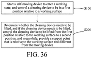
- A control method for a cleaning robot is provided, where the cleaning robot includes: a body; a moving device, configured to support the body and drive the cleaning robot to move; a cleaning device, configured to be mounted on the body and perform cleaning work on a working surface; a control device, configured to control the moving device to drive the cleaning robot to move; and a power device, configured to supply power to the moving device; and the control method includes the following steps: starting the cleaning robot to enter a working state, and controlling the cleaning device to be in a first position relative to the working surface; and determining whether the cleaning device needs to be lifted, and if the cleaning device needs to be lifted, controlling the cleaning device to be lifted from the first position relative to the working surface to a second position, and meanwhile, providing a support point that is relative to the working surface and different from the moving device.
- In an embodiment, the cleaning device includes a mopping module.
- In an embodiment, when an obstacle is detected, it is determined that the mopping module needs to be lifted, and the mopping module is controlled to be lifted to the second position; and after the cleaning robot crosses the obstacle, the mopping module is controlled to return to the first position.
- In an embodiment, when it is detected that a degree of staining or a degree of damage of the mopping module reaches a preset value, a mopping module replacement program is started; and in the mopping module replacement program, it is determined that the mopping module needs to be lifted, and the mopping module is controlled to be lifted to the second position.
- In an embodiment, when it is detected that a cleaning time or a cleaning area of the cleaning robot reaches a preset value, a mopping module replacement program is started; and in the mopping module replacement program, it is determined that the mopping module needs to be lifted, and the mopping module is controlled to be lifted to the second position.
- In an embodiment, when it is detected that a cleaning frequency of the cleaning robot reaches a preset value, a mopping module replacement program is started; and in the mopping module replacement program, it is determined that the mopping module needs to be lifted, and the mopping module is controlled to be lifted to the second position.
- In an embodiment, when a carpet is detected, it is determined that the mopping module needs to be lifted, and the mopping module is controlled to be lifted to the second position; and when a floor is detected, the mopping module is controlled to return to the first position.
- In an embodiment, when a detected battery level is lower than a preset value, a base station returning program is started; and in the base station returning program, it is determined that the mopping module needs to be lifted, and the mopping module is controlled to be lifted to the second position.
- In an embodiment, when it is detected that the cleaning robot is trapped or stuck, it is determined that the mopping module needs to be lifted, and the mopping module is controlled to be lifted to the second position.
- In an embodiment, when a detected collision frequency is greater than a preset value, it is determined that the cleaning robot is trapped or stuck.
- In an embodiment, when a detected speed or acceleration is continuously not in a preset value range, it is determined that the cleaning robot is trapped or stuck.
- In an embodiment, when it is detected that a current position of the cleaning robot remains unchanged within a preset time, it is determined that the cleaning robot is trapped or stuck.
- In an embodiment, when it is determined that the cleaning robot tilts upward, it is determined that the mopping module needs to be lifted, and the mopping module is controlled to be lifted to the second position; and when it is determined that the cleaning robot tilts downward, the mopping module is controlled to be lowered to the first position.
- In an embodiment, when it is detected that the cleaning robot reaches a base station, it is determined that the mopping module needs to be lifted, and the mopping module is controlled to be lifted to the second position.
- In an embodiment, when it is detected that the cleaning robot reaches a position of unloading the mopping module, the mopping module is controlled to be lifted from the second position relative to the working surface to a third position of unloading the mopping module or the mopping module is controlled to be separated from the body in the second position relative to the working surface.
- In an embodiment, an electromagnet matching a magnet on the mopping module is disposed on the body, and when it is detected that the cleaning robot reaches the position of unloading the mopping module, the mopping module is controlled to be separated from the body in the second position by controlling a magnitude or a direction of a current of the electromagnet.
- In an embodiment, when it is detected that the cleaning robot reaches a position of loading the mopping module, the mopping module is controlled to move to the first position or a fourth position.
- In an embodiment, the fourth position is higher than or equal to the first position and lower than the second position.
- In an embodiment, the mopping module is disposed at a front end of the body.
- In an embodiment, the support point is located between the mopping module and the moving device.
- In an embodiment, the support point is located in front of the mopping module.
- A control method for a cleaning robot is provided, where the cleaning robot includes: a body; a moving device, configured to support the body and drive the cleaning robot to move; a cleaning device, configured to be mounted on the body and perform cleaning work on a working surface; a control device, configured to control the moving device to drive the cleaning robot to move; and a power device, configured to supply power to the moving device; the cleaning device includes a mopping module, and the mopping module is detachably mounted on the body; and the control method includes the following steps: starting the cleaning robot to enter a working state, and controlling the mopping module to be in a first position relative to the working surface; and determining whether the mopping module needs to be replaced, and if the mopping module needs to be replaced, controlling the mopping module to be lifted from the first position relative to the working surface to a second position, and meanwhile, providing a support point that is relative to the working surface and different from the moving device.
- In an embodiment, wherein when it is detected that a degree of staining or a degree of damage of the mopping module reaches a preset value, it is determined that the mopping module needs to be replaced; and a mopping module replacement program is started, and in the mopping module replacement program, the mopping module is controlled to be lifted to the second position.
- In an embodiment, wherein when it is detected that a cleaning time or a cleaning area of the cleaning robot reaches a preset value, it is determined that the mopping module needs to be replaced; and a mopping module replacement program is started, and in the mopping module replacement program, the mopping module is controlled to be lifted to the second position.
- In an embodiment, wherein when it is detected that a cleaning frequency of the cleaning robot reaches a preset value, it is determined that the mopping module needs to be replaced; and a mopping module replacement program is started, and in the mopping module replacement program, the mopping module is controlled to be lifted to the second position.
- In an embodiment, wherein when it is detected that a battery level is lower than a preset value, it is determined that the mopping module needs to be replaced; and a mopping module replacement program is started, and in the mopping module replacement program, the mopping module is controlled to be lifted to the second position.
- In an embodiment, wherein when it is detected that the cleaning robot reaches a position of unloading the mopping module, the mopping module is controlled to be separated from the body.
- A ground treatment system, comprising a base station and a cleaning robot, wherein the cleaning robot comprises: a body; a moving device, configured to support the body and drive the cleaning robot to move; a control device, configured to control the moving device to drive the cleaning robot to move; and a power device, configured to supply power to the moving device; the ground treatment system further comprises a mopping module, capable of being mounted on the body and configured to perform mopping work;
- the cleaning robot further comprises a lifting device and a detection device, the lifting device comprises a lifting mechanism and a support member, and the control device is capable of controlling the lifting mechanism to lift the mopping module from a first position relative to a working surface to a second position; the support member is configured to provide a support point that is relative to the working surface and that is different from the moving device when the mopping module is lifted; and the detection device is configured to detect whether the mopping module needs to be replaced;
- the base station is provided with a mop groove configured to contain the mopping module, and a mopping module replacement device; and
- when the detection device detects that the mopping module needs to be replaced, the control device controls the cleaning robot to start a mopping module replacement program, and to return to the base station and replace the mopping module in the base station in the mopping module replacement program; and in the mopping module replacement program, the control device controls the lifting mechanism to lift the mopping module to at least the second position.
- In an embodiment, wherein the lifting mechanism comprises a mopping module lifting mechanism, and when the detection device detects that a degree of staining or a degree of damage of the mopping module reaches a preset value, the control device controls the cleaning robot to start the mopping module replacement program and to return to the base station in the mopping module replacement program, and controls the mopping module lifting mechanism to lift the mopping module from the first position relative to the working surface to the second position.
- In an embodiment, wherein the lifting mechanism comprises a mopping module lifting mechanism, the mopping module is detachably mounted on the body, and after the cleaning robot reaches a position of unloading the mopping module in the base station, the control device controls the mopping module lifting mechanism to cause the mopping module to be separated from the body in the second position.
- In an embodiment, the ground treatment system according to
claim 41, wherein the cleaning robot further comprises an unloading device, and the unloading device is disposed on the body; and the mopping module is detachably mounted on the body, and after the cleaning robot reaches a position of unloading the mopping module in the base station, the control device controls the unloading device to cause the mopping module to be separated from the body at least in the second position. - In an embodiment, wherein the control device controls the cleaning robot to continue to move, and after the cleaning robot reaches a position of loading the mopping module in the base station, the control device controls the lifting mechanism to cause the mopping module to be in the first position or a fourth position, the fourth position being higher than or equal to the first position and lower than the second position.
- Compared with the prior art, the beneficial effects of the present invention are that the cleaning robot can detect whether the mopping module needs to be replaced during work, and control lifting and falling of the mopping module according to a detection result. The cleaning robot can automatically unload a mop or automatically return to a base station to replace a mop, thereby reducing manual participation and keeping clean and hygienic. In addition, when returning to the base station or a specified place to unload an old mop or load a new mop, the cleaning robot lifts the mop in time, which can effectively avoid secondary contamination or cross contamination, and a cleaning effect is better.
- To describe the technical solutions in the specific implementations of the present invention more clearly, the following briefly describes the accompanying drawings required for describing the specific implementations. Apparently, the accompanying drawings in the following description show some embodiments of the present invention, and a person of ordinary skill in the art may still derive other drawings from these accompanying drawings without creative efforts.
-
FIG. 1 is a schematic diagram of a ground treatment system according to an embodiment of the present invention. -
FIG. 2 is a schematic diagram of a cleaning robot according to an embodiment of the present invention. -
FIG. 3 is a top view of the cleaning robot shown inFIG. 2 . -
FIG. 4 is a module diagram of a cleaning robot according to an embodiment of the present invention. -
FIG. 5 is a schematic diagram when a mopping module of a cleaning robot is in a first position according to an embodiment of the present invention. -
FIG. 6 is a schematic diagram when the mopping module of the cleaning robot shown inFIG. 5 is in a second position. -
FIG. 7 is a schematic diagram when a mopping module of a cleaning robot is in a first position according to another embodiment of the present invention. -
FIG. 8 is a schematic diagram when the mopping module of the cleaning robot shown inFIG. 7 is in a second position. -
FIG. 9 is a structural diagram of a mopping module lifting mechanism of a cleaning robot according to an embodiment of the present invention. -
FIG. 10 is a structural diagram of a mopping module lifting mechanism of a cleaning robot according to another embodiment of the present invention. -
FIG. 11 is a schematic diagram when the mopping module of the cleaning robot shown inFIG. 5 is in a third position. -
FIG. 12 is a schematic diagram when the mopping module of the cleaning robot shown inFIG. 5 falls. -
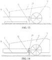
FIG. 13 and FIG. 14 are schematic diagrams in which a support member of a cleaning robot is movably connected to a body according to an embodiment of the present invention. -
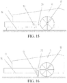
FIG. 15 and FIG. 16 are schematic diagrams in which a support member of a cleaning robot is movably connected to a body according to another embodiment of the present invention. -
FIG. 17 is a schematic diagram in which a support member of a cleaning robot is movably connected to a body according to another embodiment of the present invention. -
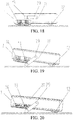
FIG. 18 to FIG. 20 are schematic diagrams in which a support member of a cleaning robot is movably connected to a body according to another embodiment of the present invention. -
FIG. 21 is a partial schematic diagram of a cleaning robot according to another embodiment of the present invention. -
FIG. 22 is a schematic diagram in which a cleaning robot works normally according to another embodiment of the present invention. -
FIG. 23 is a schematic diagram in which the cleaning robot ofFIG. 22 detects a carpet and lifts a mopping module. -
FIG. 24 is a schematic diagram in which the cleaning robot ofFIG. 22 moves on a carpet and lifts a mopping module. -
FIG. 25 is a schematic diagram in which the cleaning robot ofFIG. 22 is in contact with a floor again after passing through the carpet; -
FIG. 26 is a schematic diagram in which a cleaning robot works normally according to another embodiment of the present invention. -
FIG. 27 is a schematic diagram in which a mopping module of the cleaning robot shown inFIG. 26 is lifted and the cleaning robot crosses an obstacle. -
FIG. 28 is a schematic diagram after a mopping module of the cleaning robot shown inFIG. 26 is lifted and the cleaning robot crosses an obstacle. -
FIG. 29 is a schematic diagram in which a cleaning robot works normally according to an embodiment of the present invention. -
FIG. 30 is a schematic diagram in which a body of the cleaning robot shown inFIG. 29 is lifted and the cleaning robot crosses an obstacle. -
FIG. 31 is a schematic diagram after a body of the cleaning robot shown inFIG. 29 is lifted and the cleaning robot crosses an obstacle. -
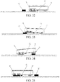
FIG. 32 is a schematic diagram in which a cleaning robot works normally according to another embodiment of the present invention. -
FIG. 33 is a schematic diagram in which a mopping module is lifted when the cleaning robot inFIG. 32 crosses an obstacle and a front portion of the body is lifted. -
FIG. 34 is a schematic diagram in which a mopping module falls when the cleaning robot inFIG. 32 crosses an obstacle and a tail portion of the body is lifted. -
FIG. 35 is a schematic diagram in which the cleaning robot inFIG. 32 is in contact with the ground again after crossing an obstacle. -
FIG. 36 is a flowchart of a control method for a cleaning robot according to an embodiment of the present invention. -
FIG. 37 to FIG. 39 are schematic diagrams of a process in which a cleaning robot automatically replaces a mop according to an embodiment of the present invention. -
FIG. 40 to FIG. 43 are schematic diagrams of a process in which a cleaning robot automatically replaces a mop according to another embodiment of the present invention. -
FIG. 44 is a schematic diagram of a cleaning robot according to another embodiment of the present invention. -
FIG. 45 is a top view of the cleaning robot shown inFIG. 44 . -
FIG. 46 is a schematic structural diagram of a mopping module lifting mechanism according to a third embodiment. -
FIG. 47 is a schematic structural diagram of a mopping module lifting mechanism according to a fourth embodiment. -
FIG. 48 is a schematic structural diagram of a mopping module lifting mechanism according to a fifth embodiment. -
FIG. 49 and FIG. 50 are schematic diagrams in which a support member of a cleaning robot is movably connected to a body according to another embodiment of the present invention. -
FIG. 51 is a schematic diagram in which a support member of a cleaning robot is movably connected to a body according to another embodiment of the present invention. -
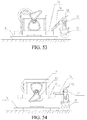
FIG. 52 andFIG. 53 are schematic diagrams in which a support member of a cleaning robot is movably connected to a body according to another embodiment of the present invention. -
FIG. 54 is a schematic structural diagram in which a mop in a mopping module falls according to the fifth embodiment. -
FIG. 55 to FIG. 57 are schematic diagrams of a process in which a mopping module of a cleaning robot falls according to an embodiment of the present invention. -
FIG. 58 to FIG. 60 are schematic diagrams of a process in which a mopping module of a cleaning robot falls according to another embodiment of the present invention. -
FIG. 61 to FIG. 65 are schematic diagrams of a process in which a cleaning robot detects a ground state and controls lifting and falling of a mopping module according to another embodiment of the present invention. -
FIG. 66 to FIG. 69 are schematic diagrams of a process in which a cleaning robot detects a ground state and controls lifting and falling of a mopping module according to another embodiment of the present invention. -
FIG. 70 is a schematic diagram of mounting of a mopping module position detection device and a position mark of a cleaning robot according to an embodiment of the present invention. -
FIG. 71 is a schematic diagram when a mopping module of a cleaning robot is in a first position according to the fifth embodiment. -
FIG. 72 is a schematic diagram when a mopping module of a cleaning robot is in a second position according to the fifth embodiment. -
FIG. 73 is a schematic structural diagram in which a mop of a mopping module of a cleaning robot falls according to the fifth embodiment. -
FIG. 74 is a schematic structural diagram of a stop device of the cleaning robot inFIG. 71 . -
FIG. 75 is a flowchart of a control method for a cleaning robot according to another embodiment of the present invention. - Corresponding reference numbers of related components are as follows:
1. Cleaning robot 2. Base station 10. Detection device 20. Fixed plate 30. Control device 40. Moving device 50. Cleaning device 11. Body 12. Driving wheel 13. Support wheel 14. Mopping module 15. Elevating motor 16. Two-stage gear reduction mechanism 17. Pressure spring 18. Magnetic element 19. Elevating frame 21. Screw rod 22. Sliding groove 23. Chain 24. Gear 29. Support member adjustment mechanism 31. Elastic member 33. Liquid tank 34. First position 35. Carpet 36. Second position 37. Obstacle 38. Obstacle detection sensor 39. Dust-collecting box 201. First docking position 202. Second docking position 203. New mop groove 204. Old mop groove 205. Upper plate 206. Support plate 207. Bottom plate 60. Power supply device 70. Power device 41. Roller brush 42. Side brush 43. First link mechanism 44. Second link mechanism 45. Third link mechanism 46. Fourth link mechanism 47. Transmission shaft 48. Fifth link mechanism 49. Sixth link mechanism 51. First cam mechanism 52. Second cam mechanism 53. First rack 54. Fixed gear 55. Second rack 56. Seventh link mechanism 57. Eighth link mechanism 58. Elastic member 26. Movable support mechanism 59. Magnet 60. Electromagnet 61. Push- pull electromagnet 62. Push rod 63. Limit device 64. First bevel 65. Second bevel 66. Position mark 67. Magnetic detection device 68. Stop device - The technical solutions in the present invention are clearly and completely described below with reference to the accompanying drawings. Apparently, the described embodiments are merely some of rather than all of the embodiments of the present invention. All other embodiments obtained by a person of ordinary skill in the art based on the embodiments of the present invention without creative efforts shall fall within the protection scope of the present invention.
-
FIG. 1 is a schematic diagram of a ground treatment system according to an embodiment of the present invention, and the ground treatment system includes abase station 2 and acleaning robot 1. The cleaningrobot 1 may be a domestic and/or indoor service robot, for example, a ground cleaning robot. Specifically, the ground cleaning robot may be an automatic mopping machine, or an automatic mopping and sweeping integrated machine, or an automatic sweeper. The cleaningrobot 1 works in a working region to complete tasks such as mopping and sweeping. When the cleaningrobot 1 needs to return to thebase station 2, for example, when it is detected that a cleaning device needs to be replaced or thecleaning robot 1 needs to be charged, a base station returning program is started, and thecleaning robot 1 returns to thebase station 2 to complete an automatic replacement action of a wiping member and/or a charging action. - The
base station 2 includes abottom plate 207, asupport plate 206, and anupper plate 205, and theupper plate 205 is connected to thebottom plate 207 by thesupport plate 206. Anew mop groove 203, anold mop groove 204, and a mop replacement device (not shown in the figure) are disposed on theupper plate 205, the mop replacement device may adopt an elevating mechanism, a swing mechanism, or the like, and projections of thenew mop groove 203 and theold mop groove 204 on thebottom plate 207 correspond to asecond docking position 202 and afirst docking position 201 of the cleaningrobot 1 on thebottom plate 207. It may be understood that positions of thenew mop groove 203 and theold mop groove 204 are not fixed. For example, in another embodiment, the positions of thenew mop groove 203 and theold mop groove 204 may be alternatively interchangeable. The cleaningrobot 1 unloads an old wiping member in thefirst docking position 201, the mop replacement device of thebase station 2 recycles the old wiping member, and the mop replacement device of thebase station 2 releases a new wiping member, so that the cleaningrobot 1 loads the new wiping member in the second docking position. The wiping member may be a mop, a wet wipe, a cleaning paper, a sponge eraser, or the like. In this embodiment of the present invention, an example in which the wiping member is the mop is used for description. Another type of wiping member is also applicable, and details are not described again. -
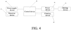
FIG. 2 andFIG. 3 show a cleaning robot according to an embodiment of the present invention. In this embodiment, the cleaningrobot 1 is a cleaning robot, and specifically is an automatic mopping machine. With reference toFIG. 4 , the cleaningrobot 1 includes abody 11, adetection device 10, acontrol device 30, a movingdevice 40, acleaning device 50, apower supply device 60, and apower device 70. - The moving
device 40 is configured to support thebody 11 and drive the cleaningrobot 1 to move, and the moving device is disposed at a rear end of thebody 11. In this embodiment, the movingdevice 40 specifically includes two drivingwheels 12 that are located on two sides of the cleaningrobot 1 and that may be independently driven by thepower device 70. Such a configuration can control a traveling speed and a direction of the movingdevice 40 by controlling speeds of the two driving wheels and a speed difference, so that moving and steering of the cleaningrobot 1 are flexible and accurate. The movingdevice 40 may be in another form such as a crawler type. - The
power device 70 provides power for thecleaning robot 1 to move and work. Specifically, the power device includes a motor located in thecleaning robot 1 and a transmission mechanism connected to the motor and provides power for the movingdevice 40. The transmission mechanism is connected to the movingdevice 40, the motor drives the transmission mechanism to work, and a transmission effect of the transmission mechanism enables the movingdevice 40 to move. The movingdevice 40 receives an instruction from thecontrol device 30 and drives the cleaningrobot 1 to automatically move on a working surface. - The
control device 30 is a control center of the cleaningrobot 1 and is electrically connected to devices such as thepower device 70, thepower supply device 60, and thedetection device 10, to receive information sent by the devices. Thecontrol device 30 controls thepower device 70 to drive the movingdevice 40 to drive the cleaningrobot 1 to move, and controls the cleaningrobot 1 to perform various actions, tasks, or the like such as switching between working regions, returning to the base station, and charging. Thecontrol device 30 may be an embedded digital signal processor (DSP), a microprocessor unit (MPU), an application-specific integrated circuit (ASIC), a programmable logic device (PLD), a system on chip (SOC), a central processing unit (CPU), a field programmable gate array (FPGA), or the like. - The
power supply device 60 provides energy for thecontrol device 30, thepower device 70, thedetection device 10, and the like of the cleaningrobot 1 to work. Thepower supply device 60 is generally a rechargeable battery and provides power for the cleaning robot to run, or may be connected to an external power supply for charging. Preferably, thepower supply device 60 has a charging or discharging protection unit, which can protect charging or discharging of thepower supply device 60. - The
cleaning device 50 is configured to be mounted on thebody 11. Thecleaning device 50 includes amopping module 14, and themopping module 14 includes a mopping plate, on which a mop can be detachably mounted, and is configured to perform mopping work of the cleaningrobot 1. In this embodiment, the moppingmodule 14 is disposed at a front end of thebody 11, a mopping area is larger, and a mopping effect is better. Certainly, it may be understood that in another embodiment, the moppingmodule 14 may be alternatively disposed at an intermediate end or a rear end of thebody 11. - In another embodiment, the cleaning
robot 1 is an automatic sweeping and mopping integrated machine and includes a dust-collecting device and a cleaning device. Thecleaning device 50 includes a mopping module, a roller brush, and a side brush. In this embodiment, referring toFIG. 44 and FIG. 45 , the moppingmodule 14 is disposed at a front part of thebody 11 and located among theroller brush 41 and theside brush 42 and thedriving wheel 12. Such an arrangement makes it convenient for thecleaning robot 1 to first sweep the ground and then mop the ground, thereby enhancing a cleaning effect. The roller brush and side brush mechanism adopts a common roller brush and a common side brush in the industry, which are configured to clean sundries such as dust on a ground, a corner, and the like. The dust-collecting device includes components such as a dust-collectingbox 39 and a fan. Dust cleared by theroller brush 41, theside brush 42, and the like is collected into the dust-collectingbox 39 through suction generated by using the fan. - In this embodiment of the present invention, the cleaning
robot 1 further includes a lifting device, configured to lift thecleaning device 50. In an embodiment, the lifting device is configured to lift themopping module 14. The lifting device includes a lifting mechanism, and thecontrol device 30 can control the lifting mechanism to lift themopping module 14 from a first position relative to the working surface to a second position. The lifting action from the first position to the second position may be performed in a direction perpendicular to the working surface, or may be performed in a direction at a specific angle to the working surface. -
FIG. 5 and FIG. 6 are schematic diagrams when a mopping module is in a first position and in a second position respectively according to an embodiment of the present invention. When in the first position, the moppingmodule 14 is in close contact with the working surface and performs mopping work in this state. When themopping module 14 needs to be lifted, thecontrol device 30 controls the lifting mechanism to cause themopping module 14 to leave the working surface and lift the mopping module from the first position to the second position. In this embodiment, the lifting process is performed in the direction perpendicular to the working surface. In this embodiment, thebody 11 of the cleaningrobot 1 is not lifted in the process of lifting themopping module 14, that is, the moppingmodule 14 is displaced relative to thebody 11 of the cleaningrobot 1. -
FIG. 7 and FIG. 8 are schematic diagrams when a mopping module is in a first position and in a second position respectively according to another embodiment of the present invention. Similarly, when in the first position, the moppingmodule 14 is in close contact with the working surface and performs mopping work in this state. When themopping module 14 needs to be lifted, thecontrol device 30 controls the lifting mechanism to cause themopping module 14 to leave the working surface and lift the mopping module from the first position to the second position. In this embodiment, the lifting process is performed in the direction at a specific angle to the working surface. In this embodiment, thebody 11 of the cleaningrobot 1 is lifted in the process of lifting themopping module 14, and the mopping module is not displaced relative to thebody 11 of the cleaningrobot 1. - In a working process of the cleaning robot, the control device can determine, according to a detection result of the detection device, whether the mopping module needs to be lifted, and control lifting and falling of the mopping module by using the lifting device. An advantage of this practice is that the cleaning robot still has better passability even when encountering a change in the ground state, for example, when encountering a carpet or an obstacle, and can avoid dirtying the carpet, the obstacle, or the like. In addition, when the cleaning robot returns to the base station or switches between working regions, the control device controls the lifting device to lift the mopping module in time, thereby effectively preventing secondary contamination or cross contamination and achieving a better cleaning effect.
- In an embodiment, the lifting device includes a support member, and the support member may provide, when the
mopping module 14 is lifted, a support point that is relative to the working surface and different from the movingdevice 40. As shown inFIG. 5 to FIG. 8 , the support member includes asupport wheel 13. As shown inFIG. 5 andFIG. 7 , when the mopping module of the cleaningrobot 1 is in the first position, that is, when the mopping module is in close contact with the working surface and performs mopping work, adriving wheel 12 supports a rear end of thebody 11, and the mopping module supports a front end of the body due to being in contact with the working surface. Under the action of thedriving wheel 12, the cleaningrobot 1 completes the mopping work while moving. However, when the mopping module is lifted, the front end of thebody 11 falls under the action of its own weight if there is no action of the support member and is in contact with the working surface. In this case, under the action of thedriving wheel 12, the cleaningrobot 1 is pushed to continue to move, but the front end of thebody 11 is always in contact with the working surface, which hinders the movement of the cleaningrobot 1. If the working surface is a floor, the floor is scratched during the movement of the cleaningrobot 1; if the working surface is a carpet, the front end of the body of the cleaningrobot 1 is in contact with the carpet, and phenomena such as getting stuck and incapable of crossing the carpet occur; and if there is an obstacle such as a step in the working surface, the cleaningrobot 1 cannot pass through the obstacle. Therefore, the support member is disposed for thecleaning robot 1, so that when themopping module 14 is lifted, the support member provides the support point that is relative to the working surface and different from the movingdevice 40, thereby avoiding the occurrence of the above phenomena, as shown inFIG. 6 andFIG. 8 . - As shown in
FIG. 5 to FIG. 8 , in an embodiment, the support point is located between the moppingmodule 14 and thedriving wheel 12. An advantage of this configuration is that a space available for themopping module 14 is increased, that is, a relatively large mopping area can be provided, thereby improving the cleaning efficiency of the cleaning robot. Certainly, it may be understood that the support point may be alternatively disposed at the front end of thebody 11, for example, the support point is disposed in front of themopping module 14. In addition, the support member may be fixedly connected to thebody 11, or may be movably connected to thebody 11. The support member may be always in contact with the working surface to provide the support point. For example, the support member may be in contact with the working surface but in a floating state when themopping module 14 is not lifted, and the support member is in close contact with the working surface for supporting when themopping module 14 is lifted. Alternatively, the support member may be in contact with the working surface only when themopping module 14 is lifted, to provide the support point. - As shown in
FIG. 5 and FIG. 6 , in an embodiment, the lifting mechanism of the cleaningrobot 1 includes a mopping module lifting mechanism (not shown in the figure) capable of driving themopping module 14 to be lifted from the first position relative to the working surface to the second position. In this embodiment, the mopping module lifting mechanism is an elevating mechanism, and the elevating mechanism may include an elevating motor, a transmission mechanism, and an elevating detection unit. The transmission mechanism is driven by using the elevating motor to drive the moppingmodule 14 to move upward or downward, and the control device controls, according to a detection result of the elevating detection unit, the mopping module to move upward or downward. - In an embodiment of this application, the elevating detection unit may detect, according to a rotation angle of a motor, or a rotation angle of a transmission shaft, or a position change of the mopping module lifting mechanism, whether the
mopping module 14 reaches conditions such as the first position or the second position of the corresponding working surface. When these conditions are reached, the control device controls the elevating motor to pause. For example, when the mopping module is lifted from the first position relative to the working surface to the second position, the elevating detection unit detects whether the rotation angle of the elevating motor reaches a preset threshold. The preset threshold is related to the rotation angle of the elevating motor when the mopping module is in a condition such as the second position of the corresponding working surface. During the movement of the mopping module, when the elevating detection unit detects that the rotation angle of the elevating motor reaches an angle threshold corresponding to the second position, the control device controls the elevating motor to pause working, that is, controls the mopping module to pause lifting. When the elevating detection unit detects that the rotation angle or the rotation radian of the elevating motor or the rotation angle or the rotation radian of the transmission mechanism does not reach the preset threshold, the control device controls the elevating motor to continue to work, that is, controls the mopping module to continue to lift. In an embodiment of this application, the elevating detection unit may be an optical grating, a Hall sensor, an infrared sensor, or another condition. The rotation angle of the motor may be detected by using the optical grating, the rotation angle of the transmission shaft may be detected by using the Hall sensor, the position change of the mopping module lifting mechanism may be detected by using the infrared sensor, or the like. This is not limited in this application. - In another embodiment, the mopping module lifting mechanism may be alternatively a swing mechanism, and the
mopping module 14 is driven by using the swing mechanism to be lifted from the first position relative to the working surface to the second position. -
FIG. 9 is a structural diagram of a mopping module lifting mechanism according to this embodiment. In this embodiment, the mopping module lifting mechanism can adjust a distance between the moppingmodule 14 and the working surface. Specifically, the mopping module lifting mechanism includes an elevating mechanism and a fixedplate 20. The elevating mechanism is fixedly connected to the fixedplate 20 and themopping module 14 is mounted on the fixedplate 20. The elevating mechanism includes an elevatingmotor 15 and a transmission mechanism. The transmission mechanism includes agear 16 andscrew rod 17 meshed device and an elevatingframe 19, and the elevatingmotor 15 drives the transmission mechanism to drive the moppingmodule 14 to move upward or downward. Specifically, the elevatingframe 19 drives, under the action of the elevating mechanism, the moppingmodule 14 to move upward or downward relative to the working surface. - A sliding
groove 22 is provided on the elevatingframe 19, a corresponding protrusion (not shown in the figure) is disposed on thebody 11, and themopping module 14 moves upward or downward relative to thebody 11 through engagement between the slidinggroove 22 and the protrusion. Certainly, it may be understood that themopping module 14 may alternatively move upward or downward relative to thebody 11 through engagement between internal and external threads disposed on the elevating frame and the body. In another embodiment, the mopping module lifting mechanism may be alternatively a swing mechanism. The elevatingframe 19 drives, under the action of the swing mechanism, the moppingmodule 14 to swing, to adjust a distance between the moppingmodule 14 and the working surface. In this case, a moving path of themopping module 14 is in an arc shape. A specific structure is a common structure of an adjusting device, which is not described herein again. -
FIG. 10 is a structural diagram of a mopping module lifting mechanism according to another embodiment. The mopping module lifting mechanism includes an elevating mechanism and a fixedplate 20. The elevating mechanism is fixedly connected to the fixedplate 20 and amopping module 14 is mounted on the fixedplate 20. Specifically, the elevating mechanism includes an elevatingmotor 15 and a transmission mechanism, and the elevatingmotor 15 drives the transmission mechanism to drive the moppingmodule 14 to move upward or downward. In this embodiment, the transmission mechanism includes belt transmission devices and an elevatingframe 19. Specifically, a motor shaft of the elevatingmotor 15 is connected to a two-stagegear reduction mechanism 16, each of two ends of an output shaft of thereduction mechanism 16 is connected to a belt transmission device formed by threegears 24 and achain 23, and the belt transmission devices are fixedly connected to the elevatingframe 19, to drive the moppingmodule 14 to move in a transmission process. It may be understood that a transmission mechanism formed by engagement between gear and rack devices may be alternatively adopted. -
FIG. 46 is a schematic structural diagram of a mopping module lifting mechanism according to a third embodiment. The mopping module lifting mechanism may include an elevating mechanism and a fixedplate 20, the elevating mechanism may include an elevatingmotor 15 and a transmission mechanism, and the elevatingmotor 15 drives the transmission mechanism to drive the mopping module to move upward or downward. In this embodiment, the transmission mechanism may include a gear and transmission shaft interference device and first linkage mechanisms each formed by a four-stage link, and the two first linkage mechanisms are rotatably connected to the fixedplate 20 by pin shafts. Specifically, the motor shaft of the elevatingmotor 15 is respectively connected to twogear 24 andtransmission shaft 47 interference devices, the first linkage mechanisms are driven respectively by the twotransmission shafts 47, and each first linkage mechanism may include a first link mechanism 43 of which one end is fixedly connected to the elevatingmotor 15, a second link mechanism 44 of which one end is linked to the other end of the first link mechanism 43, athird link mechanism 45 of which one end is rotatably connected to the body and the other end is linked to the other end of the second link mechanism 44, and a fourth link mechanism 46 of which one end is linked to the other end of thethird link mechanism 45 and the other end is linked to the fixedplate 20. The elevating motor drives each first linkage mechanism to drive the fixedplate 20 to move upward or downward, to drive the mopping module to move in a transmission process of the mopping module lifting mechanism. -
FIG. 47 is a schematic structural diagram of a mopping module lifting mechanism according to a fourth embodiment. The mopping module lifting mechanism may include an elevating mechanism and a fixedplate 20, the elevating mechanism may include an elevatingmotor 15 and a transmission mechanism, and the elevatingmotor 15 drives the transmission mechanism to drive the mopping module to move upward or downward. In this embodiment, the transmission mechanism may include a gear and transmission shaft interference device and second linkage mechanisms each formed by a two-stage link, and the two second linkage mechanisms are rotatably connected to the fixedplate 20 by pin shafts fixed on the body. Specifically, the motor shaft of the elevatingmotor 15 is connected to one gear andtransmission shaft 47 interference device, each of two ends of thetransmission shaft 47 is connected to the second linkage mechanism formed by the two-stage link, and each second linkage mechanism may include afifth link mechanism 48 fixedly connected to thetransmission shaft 47, where one end of thefifth link mechanism 48 is linked to one end of asixth link mechanism 49, and the other end of thesixth link mechanism 49 is linked to the fixedplate 20. The elevatingmotor 15 drives each second linkage mechanism to drive the fixedplate 20 to move upward or downward, to drive the mopping module to move in a transmission process of the mopping module lifting mechanism. -
FIG. 48 is a schematic structural diagram of a mopping module lifting mechanism according to a fifth embodiment. The mopping module lifting mechanism may include an elevating mechanism and a fixedplate 20, the elevating mechanism may include an elevatingmotor 15 and a transmission mechanism, and the elevatingmotor 15 drives the transmission mechanism to drive the mopping module to move upward or downward. In this embodiment, the transmission mechanism may include a gear and transmission shaft interference device andfirst cam mechanism 51 and elevatingframe 19 combined devices. The elevatingframe 19 is fixedly connected to the fixedplate 20, thefirst cam mechanism 51 is mounted in the elevatingframe 19, and themopping module 14 is mounted on the elevatingframe 19. Specifically, the motor shaft of the elevatingmotor 15 is connected to one gear andtransmission shaft 47 interference device, two ends of thetransmission shaft 47 are respectively connected to thefirst cam mechanism 51 and elevatingframe 19 combined devices, and thefirst cam mechanism 51 rotates around thetransmission shaft 47 as a center point, to drive the elevatingframe 19 to move upward or downward and control lifting and falling of the fixedplate 20, thereby implementing lifting and falling of themopping module 14 relative to the working surface.FIG. 52 is a schematic structural diagram when a mopping module is lifted. When thefirst cam mechanism 51 rotates upward to be in contact with an upper side of the elevatingframe 19, the mopping module is in a lifted state in the second position. Thefirst cam mechanism 51 may be a complete circle or the first cam mechanism may be another condition such as a semicircle or a 30-degree circle, provided that there is a distance difference between a rotation center point of the first cam mechanism and an edge of the first cam mechanism. The first cam mechanism may rotate around a point other than the center of circle of the first cam mechanism as a center point, to ensure that the fixed plate has a plurality of height conditions during work of the elevating mechanism, thereby implementing lifting and falling of the mopping module relative to the working surface. It may be understood that there may be alternatively no elevating frame, the edge of the first cam mechanism is partially connected to the mopping module, the elevating motor drives the first cam mechanism to rotate, and the first cam mechanism drives the mopping module to move upward or downward. - It should be noted that the connection mentioned in this application may be a direct connection or may be an indirect connection. The mopping module may move upward or downward under the action of the elevating motor to adjust a position, or a position of the mopping module may be adjusted through right-and-left swing or back-and-forth swing of a swing motor.
- In this embodiment, the mopping
module 14 is detachably mounted on thebody 11. More specifically, thecontrol device 30 can control themopping module 14 to be automatically separated from thebody 11, and themopping module 14 is separated from thebody 11 at least in the second position relative to the working surface. An advantage of this practice is that on the one hand, the replacement of a mopping component is more intelligent, convenient, and is clean and hygienic without manual intervention; on the other hand, to facilitate the recycling of a dirty mop, the cleaning robot generally needs to unload the mop at a designated place (for example, the base station), and when the mopping module needs to be replaced, it is mostly because the mop is already very dirty, and the mop is lifted in time to avoid dirtying the ground and causing secondary contamination. When the cleaning robot returns to the designated place, the control device controls the mopping component to unload the mop in the lifted position, or certainly the mop may be unloaded at a place higher than or lower than the position. A case that the mopping module may be automatically separated from the body is described below in detail. - With reference to
FIG. 9 , the moppingmodule 14 is mounted on the fixedplate 20 through magnetic attraction. Specifically, a magnetic element such as a magnet or a magnetic strip is disposed on themopping module 14, and is attracted to amagnetic element 18 disposed on the fixedplate 20. Alternatively, a pin hole may be provided on themopping module 14 and engaged with a corresponding pin column disposed on the fixedplate 20, to mount themopping module 14 on the fixedplate 20. A protrusion device (not shown in the figure) such as a top column or a convex ball is downwards disposed on thebody 11, and the protrusion device moves relative to themopping module 14 and is in contact with themopping module 14, so that themopping module 14 is separated from thebody 11. There are two protrusion devices, and projections of the protrusion devices on the mopping plate fall on two ends of the mopping plate. Certainly, there may be alternatively one or more than two protrusion devices. - In an embodiment, the mopping
module 14 further includes a third position relative to the working surface.FIG. 11 is a schematic diagram when a mopping module of a cleaning robot is in a third position according to the present invention. Specifically, the moppingmodule 14 is detachably mounted on thebody 11, and the mopping module lifting mechanism is further configured to drive the moppingmodule 14 to be lifted from the second position relative to the working surface to the third position of unloading themopping module 14. When themopping module 14 is lifted to the third position, the protrusion device is in contact with themopping module 14, to provide a downward action force to themopping module 14, so that themopping module 14 is separated from the body 11 (as shown inFIG. 12 ). - In another embodiment, the cleaning
robot 1 further includes an unloading device, the unloading device is disposed on thebody 11, and thecontrol device 30 can control the unloading device to cause themopping module 14 to be separated from thebody 11 at least in the second position. For example, the moppingmodule 14 may be unloaded in the third position relative to the working surface, or certainly themopping module 14 may be unloaded in the second position rather than in the third position. In this case, the unloading device is a protrusion device. The protrusion device includes an elevating mechanism, and thecontrol device 30 controls the elevating mechanism to drive the protrusion device to move toward themopping module 14 and to be in contact with themopping module 14, to provide a downward action force to themopping module 14, so that themopping module 14 is separated from thebody 11. In still another embodiment, the unloading device includes an electromagnet, matching a magnet on the mopping module, and the control device controls attraction or separation between the mopping module and the body by controlling a magnitude or a direction of a current passing through the electromagnet. Specifically, the electromagnet is disposed on thebody 11, the magnet is disposed on themopping module 14, and thecontrol device 30 controls the attraction or the separation between the moppingmodule 14 and thebody 11 by controlling the magnitude or the direction of the current passing through the electromagnet. For example, when thecontrol device 30 controls the direction of the current passing through the electromagnet to be a positive direction, the moppingmodule 14 is attracted to thebody 11. When themopping module 14 needs to be separated from thebody 11, thecontrol device 30 controls the direction of the current passing through the electromagnet to be a negative direction. Alternatively, the attraction or the separation between the moppingmodule 14 and thebody 11 may be controlled by controlling presence or absence of the current passing through the electromagnet; and when there is a current passing through the electromagnet, the moppingmodule 14 is attracted to thebody 11, and when no current passes through the electromagnet, the moppingmodule 14 is separated from thebody 11. In another embodiment, as shown inFIG. 55 to FIG. 57 , anelectromagnet 59 is disposed on thebody 11, and amagnet 60 is disposed on themopping module 14 and is attracted to themagnetic element 18 on the fixedplate 20. A quantity of magnets may be two, four, or six, or certainly may be another value. This is not limited herein. When themopping module 14 works normally, no current passes through theelectromagnet 59, and themopping module 14 is in close contact with the ground (as shown inFIG. 55 ). When themopping device 14 needs to be unloaded, the mopping module lifting mechanism drives themopping module 14 to be lifted to an unloaded position (as shown inFIG. 56 ), and meanwhile, thecontrol device 30 controls a magnitude of a current passing through theelectromagnet 59 to generate a repulsive force, to overcome attraction between the moppingmodule 14 and the fixedplate 20, so that themopping module 14 is separated from the fixedplate 20, that is, separated from thebody 11, and themopping module 14 falls (as shown inFIG. 57 ). Certainly, the mopping module may be alternatively separated from the body in another position such as the first position or the second position, and the principle is the same as the above. Compared with the foregoing embodiments, an advantage of this embodiment is that there is no need to always electrify the electromagnet when themopping module 14 works. The electromagnet needs to be electrified only when themopping module 14 is lifted to the unloaded position, to cause the mopping module to fall, thereby saving energy and avoiding an interference caused when the electromagnet is always electrified. In still another embodiment, the unloading device includes a push-pull electromagnet and a push rod engaged with an iron core of the push-pull electromagnet, and the control device controls, by electrifying the push-pull electromagnet, the push rod to act on the mopping module, so that the mopping module is separated from the body at least in the second position. As shown inFIG. 58 to FIG. 60 , a push-pull electromagnet 61 and apush rod 62 engaged with an iron core of the push-pull electromagnet are used. When themopping module 14 works normally, no current passes through the push-pull electromagnet 61, and themopping module 14 is in close contact with the ground (as shown inFIG. 58 ). When themopping device 14 needs to be unloaded, the mopping module lifting mechanism drives themopping module 14 to be lifted to the unloaded position (as shown inFIG. 56 ), and meanwhile, thecontrol device 30 controls the push-pull electromagnet 61 to start, and the push rod extends out instantaneously and is in contact with themopping module 14 to provide a downward action force to the mopping module (as shown inFIG. 57 ), to overcome attraction between the moppingmodule 14 and the fixedplate 20, so that themopping module 14 is separated from the fixedplate 20, and themopping module 14 falls (as shown inFIG. 58 ). An advantage of this embodiment is that there is no need to always electrify the push-pull electromagnet when themopping module 14 works. The push-pull electromagnet needs to be electrified only when themopping module 14 is lifted to the unloaded position, and the push rod extends out, to cause the mopping module to fall. The push rod directly acts on the mopping module to separate the mopping module from the body, and there is no need to electrify the push-pull electromagnet by using a relatively large current, thereby saving energy and achieving a more reliable effect. In still another embodiment, the unloading device includes a cam device, and the cam device includes a cam mechanism and a driving motor. Thecontrol device 30 controls the driving motor to drive the cam mechanism to rotate, and when being in contact with themopping module 14, the cam mechanism can apply a downward action force to themopping module 14, so that themopping module 14 is separated from thebody 11 at least in the second position. In still another embodiment, the unloading device includes a rod device, and the rod device includes a rod mechanism and a driving motor. Thecontrol device 30 controls the driving motor to drive the rod mechanism to rotate, and when being in contact with themopping module 14, the rod mechanism can apply a downward action force to themopping module 14, so that themopping module 14 is separated from thebody 11 at least in the second position. - In another embodiment, the mopping
module 14 may be further detachably mounted on thebody 11 in another manner.FIG. 48 andFIG. 54 are schematic structural diagrams of a mopping module lifting mechanism according to another embodiment. A mop elevating mechanism may further includesecond cam mechanisms 52. Similar to thefirst cam mechanisms 51, thesecond cam mechanisms 52 are also respectively mounted on two ends of thetransmission shaft 47 and independent of thefirst cam mechanisms 51. Thesecond cam mechanism 52 moves synchronously with thefirst cam mechanism 51, thesecond cam mechanism 52 and thefirst cam mechanism 51 should not coincide, and thesecond cam mechanism 52 can be directly in contact with themopping module 14 during rotation. The elevatingmotor 15 drives thesecond cam mechanism 52 to rotate, and when thesecond cam mechanism 52 is in contact with themopping module 14, the mopping module is in the second position, and thesecond cam mechanism 52 can apply a downward action force to themopping module 14, so that in a schematic structural diagram of falling of a mop in a mopping module shown inFIG. 54 , the moppingmodule 14 is separated from thebody 11. Thesecond cam mechanism 52 may be a complete circle or may be another condition such as a semicircle or a 30-degree circle, and the second cam mechanism rotates around a point other than the center of circle of the cam as a center point. It may be understood that the second cam mechanism may be alternatively replaced with a rod mechanism (not shown in the figure) or the like. This is not limited in this application. - In this embodiment, the cleaning
robot 1 further includes a mopping module detection device, configured to detect whether themopping module 14 is disposed on thebody 11 and send a detection signal to thecontrol device 30. Thecontrol device 30 determines, based on presence or absence of the detection signal, whether themopping module 14 is disposed on thebody 11, and if themopping component 14 is not disposed on thebody 11, the cleaning robot does not work. In an embodiment, the mopping module detection device includes a magnetic detection sensor such as a Hall sensor, a magnetic element such as a magnet is disposed on a mopping plate of themopping component 14, and the control device determines, according to a signal detected by the Hall sensor, whether themopping module 14 is mounted on thebody 11. In another embodiment, the mopping module detection device includes a photoelectric sensor, and thecontrol device 30 determines, according to a signal detected by the photoelectric sensor, whether themopping module 14 is mounted on thebody 11. In another embodiment, the mopping module detection device includes a pressure sensor, an optical sensor, an infrared sensor, or the like, which is not limited herein. - When the cleaning robot starts working or restarts working in case of emergency, by detecting whether a mopping component is disposed on the body, a problem that the ground is scratched when the cleaning robot on which no mopping component is mounted works can be prevented. In addition, whether the mopping component is disposed on the body also needs to be detected when the cleaning robot replaces the mopping module. If a detection result is that there is no mopping module on the body when a dirty mop is unloaded, it indicates that the dirty mop is unloaded successfully; and if the detection result is that there is the mopping module on the body when a new mop is mounted, it indicates that the new mop is mounted successfully, to avoid a problem that the new mop is dirtied because the dirty mop is not unloaded but replacement with the new mop is performed, or a problem that the floor is scratched because the cleaning robot works without mounting the new mop.
- Still further, to more accurately determine whether the mopping module is successfully replaced, in this embodiment, the cleaning
robot 1 further includes a mop type detection device, configured to detect a mop type such as a clean mop or a dirty mop or such as a dry mop or a wet mop, to more accurately determine whether themopping module 14 is replaced successfully. The mop type detection device includes a mop type sensor such as a capacitive sensor, a resistive sensor, a visual sensor, a humidity sensor, or a weighing sensor, and thecontrol device 30 determines a mop type by comparing a preset value with a value of a detection signal of the mop type sensor. Through detection of the mop type, the cleaning robot may determine whether the mopping module mounted on the body is a clean mopping module or a dirty mopping module or is a dry mop or a wet mop, and may automatically determine whether the mopping module is replaced successfully, to prevent the secondary contamination on the ground caused by continuous work of the cleaning robot in the case of unsuccessful replacement, which brings poor user experience. - To accurately detect a position of the mopping module, better control a position of the mopping module relative to the working surface, and better implement functions of mopping the ground, lifting to cross an obstacle, and replacing a mop.
- In this embodiment, the cleaning
robot 1 further includes a mopping module position detection device. The mopping module position detection device is disposed on thebody 11 and the mopping module position detection device is electrically connected to thecontrol device 30 and is configured to detect a position of themopping module 14 relative to the working surface and output a detection signal. Thecontrol device 30 determines the position of themopping module 14 relative to the working surface by comparing a preset value with a value of the detection signal. In an embodiment, a position mark is disposed on the mopping module lifting mechanism, and the mopping module position detection device is configured to detect the position mark and output a value of a detection signal. Thecontrol device 30 determines the position of themopping module 14 relative to the working surface by comparing the value of the detection signal with a preset value. Specifically, the mopping module position detection device includes a magnetic detection sensor such as a Hall sensor, and the position mark is a magnetic element such as a magnetic bead or a magnetic steel. When themopping component 14 is in different positions, magnetic field intensity detected by the magnetic detection sensor is different, and outputted signal values are different. Thecontrol device 30 compares each signal value with the preset value to determine whether themopping module 14 is in a required working position. Certainly, different position marks such as different infrared identifiers may be alternatively disposed in different positions of the mopping module corresponding to the body of the cleaning robot, the mopping module position detection device such as an infrared sensor is disposed on the mopping module lifting device, an infrared identifier is identified by using the infrared sensor, and a detection signal is outputted to thecontrol device 30, to determine whether themopping module 14 is in a required working position. In another embodiment, the lifting mechanism includes amovable support mechanism 26, and themovable support mechanism 26 connects the support member and the body. Thecontrol device 30 controls the movable support mechanism to drive the support member to move to an extended position, so that themopping module 14 is lifted from the first position relative to the working surface to the second position. Thecontrol device 30 controls themovable support mechanism 26 to drive the support member to move to a retracted position, so that the mopping module falls from the second position relative to the working surface to the first position. The mopping module position detection device includes a tilt sensor, configured to detect a degree of inclination of thebody 11 and output a detection signal. Thecontrol device 30 determines the position of themopping module 14 relative to the working surface by comparing a value of the detection signal with a preset value. - In another embodiment, the
control device 30 determines, by comparing a current value of the elevatingmotor 15 with a preset current value, whether the elevatingmotor 15 is blocked, and determines a current position of themopping module 14 by comparing a preset value with a signal value outputted by the position mark that is located on the mopping module lifting mechanism and that is detected by the mopping module position detection device disposed on the body. Mopping module position detection accuracy may be further improved by using this solution. Specifically, as shown inFIG. 70 to FIG. 73 , the cleaningrobot 1 further includes alimit device 63, and thelimit device 63 includes afirst bevel 64 and asecond bevel 65. When themopping module 14 is in the first position, a first part edge of thesecond cam mechanism 52 abuts against thefirst bevel 64; and when themopping module 14 is in a separated position, a second part edge of thesecond cam mechanism 52 abuts against thesecond bevel 65. As shown inFIG. 70 , the cleaningrobot 1 further includes a mopping moduleposition detection device 67, and the mopping module position detection device is disposed on the body and includes a magnetic detection sensor such as a Hall sensor. Aposition mark 66 is disposed on the elevating frame, and theposition mark 66 is a magnetic element such as a magnetic bead or a magnetic steel. The elevatingmotor 15 drives, when rotating, thefirst cam mechanism 51 and thesecond cam mechanism 52 to rotate, magnetic field intensity detected by the magnetic detection sensor is different, and outputted signal values are different. When the elevatingmotor 15 drives, when rotating in a first direction, thefirst cam mechanism 51 and thesecond cam mechanism 52 to rotate clockwise, and when the second part edge of thesecond cam mechanism 52 abuts against thesecond bevel 65, a current of the elevatingmotor 15 changes and a current value increases. The control device 3 compares the current value with a preset current value, and determines, when the current value is greater than or equal to the preset current value, that the elevatingmotor 15 is blocked; and meanwhile, thecontrol device 30 compares a first preset value with a signal value detected by the Hall sensor in this case, and determines, when the signal value reaches the first preset value, that themopping module 14 is in the separated position, as shown inFIG. 73 . In this case, the elevatingmotor 15 drives, when rotating in a second direction, thefirst cam mechanism 51 and thesecond cam mechanism 52 to rotate counterclockwise, and when the first part edge of thesecond cam mechanism 52 abuts against thefirst bevel 64, as shown inFIG. 71 , the current of the elevatingmotor 15 similarly changes and a current value increases. The control device 3 compares the current value with the preset current value, and determines, when the current value is greater than or equal to the preset current value, that the elevatingmotor 15 is blocked; and meanwhile, thecontrol device 30 compares a second preset value with a signal value detected by the Hall sensor in this case, and determines, when the signal value reaches the second preset value, that themopping component 14 is in the first position. When the elevatingmotor 15 continues to drive, when rotating in the first direction, thefirst cam mechanism 51 and thesecond cam mechanism 52 to rotate clockwise, thecontrol device 30 compares the first preset value with a signal value detected by the Hall sensor in this case, and determines, when the signal value reaches the first preset value, that the elevatingmotor 15 is not blocked; and meanwhile, the control device 3 detects a current value of the elevating motor, and determines, when the current value is less than the preset current value, that themopping module 14 is in the second position, as shown inFIG. 72 . The first direction is opposite to the second direction. In still another embodiment, a rotational speed of the elevatingmotor 15 may be alternatively detected, the current position of themopping module 14 is determined by comparing the rotational speed with a preset value and comparing a preset value with a signal value outputted by the position mark that is located on the mopping module lifting mechanism and that is detected by the mopping module position detection device on the body. In still another embodiment, the current position of the mopping module is determined in the foregoing elevating motor blockage detection manner and by detecting whether the mopping module is mounted on the body and comparing the preset value with the signal value outputted by the position mark that is located on the mopping module lifting mechanism and that is detected by the mopping module position detection device on the body. Specifically, a magnetic sensor such as a Hall sensor is disposed on the elevatingframe 19, and a magnetic element such as a magnet is disposed on the mopping plate of the mopping module. The magnetic sensor detects the magnetic element and presence or absence of an outputted signal to determine whether the mopping module is mounted on the elevatingframe 19. When it is detected that the elevating motor is blocked and the mopping module is mounted on the body, the control device determines that the mopping module is in the first position in this case. When it is detected that the elevating motor is blocked and the mopping module is not mounted on the body, the control device determines that the mopping module is in the separated position in this case. When thecontrol device 30 compares a signal value detected by the mopping module position detection device in this case with the first preset value and the signal value reaches the first preset value, the control device determines that the mopping module is in the second position in this case. Certainly, the position of the mopping module may be alternatively detected by combining the foregoing manners, and the principle is the same as the above. Details are not described herein again. - To prevent the
mopping module 14 from being stripped from the cleaningrobot 1 when encountering an obstacle such as a wire during work, bringing poor user experience to the user, in an embodiment of the present invention, as shown inFIG. 71 andFIG. 74 , the cleaningrobot 1 further includes astop device 68, and thestop device 68 is fixedly mounted on an outer side of a front end of a bottom plate of the mopping module lifting mechanism. When the cleaningrobot 1 encounters a wire, the wire is first in contact with thestop device 68 and passes through along the bottom of thestop device 68 under the action of thestop device 68, to avoid applying a force to themopping module 14 to cause themopping module 14 to be separated from the mop module lifting device. - The
mopping module 14 includes a mopping plate and a mop (not shown in the figure), and the mop is detachably mounted on the mopping plate. In an embodiment, rubber thread strips are disposed on the mopping plate at intervals, and the mop is fixed on the mopping plate by using the rubber thread strips. In another embodiment, a pasting strip is disposed on the mopping plate, and the mop is directly pasted on the mopping plate. Certainly, it may be understood that the mop may be alternatively mounted on the mopping plate in a mechanical manner such as snap-fit. According to a requirement of a working scenario, the mop may be a dry mop or a wet mop; and the mop may be a reusable mop or a disposable wet wipe. To increase a pressure between the mopping module and the working surface, so as to have better contact with the working surface and enhance the cleaning effect, in an embodiment, four vertical grooves may be provided in the elevating frame. Apressure spring 17 is disposed in each vertical groove, and when themopping module 14 works, thepressure spring 17 applies a downward squeeze force to themopping module 14 under the action of the gravity of the cleaning device. - When the
mopping module 14 of the cleaningrobot 1 is lifted, the support member is required to cooperatively provide a support point different from the driving wheel. In a corresponding embodiment, the lifting device further includes asupport wheel 13 for providing a support point different from thedriving wheel 12 for themopping module 14 when the mopping module is lifted from the first position relative to the working surface to the second position. - The following describes the design of the support member in this embodiment in detail. In this embodiment, the support member is movably connected to the
body 11, and a distance between the support member and the top of thebody 11 when themopping module 14 is in the second position is greater than a distance between the support member and the top of thebody 11 when themopping module 14 is in the first position. When themopping module 14 works normally, the support member is not in contact with the working surface; and only when themopping module 14 is lifted, the support member is in close contact with the working surface, to provide a support point different from thedriving wheel 12. -
FIG. 13 and FIG. 14 are schematic diagrams in which a support member is movably connected to a body according to an embodiment of the present invention. As shown inFIG. 13 , when themopping module 14 is in contact with the working surface and is in a normal working state, thesupport wheel 13 is in a retracted state. Specifically, the lifting device of the cleaningrobot 1 includes a supportmember adjustment mechanism 29, and the supportmember adjustment mechanism 29 drives, when themopping module 14 falls, thesupport wheel 13 to be retracted. As shown inFIG. 14 , when themopping module 14 needs to be lifted, thecontrol device 30 controls themopping module 14 to be lifted. In this case, thesupport wheel 13 is in a falling state. Specifically, the lifting device of the cleaningrobot 1 includes the supportmember adjustment mechanism 29. The supportmember adjustment mechanism 29 drives, when themopping module 14 is lifted, thesupport wheel 13 to fall, and thesupport wheel 13 is in contact with the working surface, to provide a support point that is relative to the working surface and different from thedriving wheel 12 for thecleaning robot 1. The supportmember adjustment mechanism 29 includes an elevating mechanism (not shown in the figure), the elevating mechanism includes an elevating motor and a transmission mechanism, and the elevating motor drives the transmission mechanism to drive thesupport wheel 13 to move upward or downward. Certainly, it may be understood that in another embodiment, as shown inFIG. 15 and FIG. 16 , the supportmember adjustment mechanism 29 includes a swing mechanism (not shown in the figure), and the swing mechanism includes a swing motor. The swing motor drives the transmission mechanism to drive thesupport wheel 13 to move to a retracted position (as shown inFIG. 15 ) when themopping module 14 is in the normal working state and drives the transmission mechanism to drive thesupport wheel 13 to move to a falling position (as shown inFIG. 16 ) when themopping module 14 is lifted. - In an embodiment of this application, the support member adjustment mechanism is linked to the mopping module lifting mechanism. Specifically, the support member adjustment mechanism may be linked in the following manner such as a gear and rack meshed device or a link device.
-
FIG. 49 and FIG. 50 are schematic diagrams in which a support member is movably connected to a body according to another embodiment of the present invention. The schematic diagram shows a linkage manner using a gear and rack meshed device. Specifically, the gear and rack meshed device may include afirst rack 53 linked to the mopping module lifting mechanism, a fixedgear 54 meshed with thefirst rack 53, and asecond rack 55 meshed with the fixedgear 54, where thesecond rack 55 is linked to thesupport wheel 13. Two sliding grooves are respectively provided on the body, and thefirst rack 53 and thesecond rack 55 respectively move upward or downward in the sliding grooves. As shown inFIG. 50 , the mopping module lifting mechanism drives, when being lifted, thefirst rack 53 to rise, thefirst rack 53 drives, when rising, the fixedgear 54 to rotate, the fixedgear 54 drives, when rotating, thesecond rack 54 to fall, and the second rack drives, when falling, thesupport wheel 13 to fall. Conversely, as shown inFIG. 49 , the mopping module lifting mechanism drives, when falling, thesupport wheel 13 to be retracted. -
FIG. 51 is a schematic diagram in which a support member is movably connected to a body according to another embodiment of the present invention. The schematic diagram shows a linkage manner using a link device. Specifically, the link device may include afifth link mechanism 48 fixedly connected to thetransmission shaft 47, where one end of thefifth link mechanism 48 is linked to asixth link mechanism 49, the other end of thefifth link mechanism 48 is linked to thesupport wheel 13, and a sliding groove is correspondingly provided on the body corresponding to thesupport wheel 13. The transmission shaft drives thefifth link mechanism 48 to rotate, thefifth link mechanism 48 drives, when the mopping module is lifted, thesupport wheel 13 to fall, and drives, when the mopping module falls, thesupport wheel 13 to be retracted. -
FIG. 52 andFIG. 53 are schematic diagrams in which a support member is movably connected to a body according to another embodiment of the present invention. The schematic diagram shows another linkage manner using a link device, which may include: aseventh link mechanism 56 and aneighth link mechanism 57. One end of theeighth link mechanism 57 is linked to thesupport wheel 13, the other end of the eighth link mechanism is linked to one end of theseventh link mechanism 56 by a pin column, the other end of theseventh link mechanism 56 is in contact with the fixedplate 20, a sliding groove is provided on the body corresponding to theeighth link mechanism 57, and theeighth link mechanism 57 can move upward or downward in the sliding groove. When the elevating motor drives the mopping module to rise, theseventh link mechanism 58 drives, through a transmission effect of the pin column, theeighth link mechanism 57 to fall and thesupport wheel 13 to fall. That is, when the mopping module is in a lifted state, the support wheel provides a supporting effect; and when the fixed plate falls, the link mechanisms drive the support wheel to rise. In another embodiment of this application, an elastic member is optionally sleeved on the pin column. Preferably, the elastic member may be a reset spring, and the reset spring and the pin column are coaxial. One end of the reset spring is in contact with the body, and the other end is in contact with theseventh link mechanism 58. Therefore, when the spring is reset, theseventh link mechanism 58 can effectively follow the mopping module to move downward, so that thesupport wheel 13 can be effectively controlled to rise. For this embodiment, connection and reset functions of the reset spring may be alternatively replaced with a connecting member such as a pin column. A pin column connected to the fixedplate 20 is disposed at the other end of theseventh link mechanism 56, so that the mopping module is linked to theseventh link mechanism 56. Certainly, in this state, the reset spring may be mounted on the pin column or may not be mounted on the pin column. - In another embodiment, the
support wheel 13 is movably connected to thebody 11. The support wheel is in contact with the working surface but in a floating state when themopping module 14 is not lifted, and the support wheel is in close contact with the working surface for supporting when themopping module 14 is lifted.FIG. 17 is a schematic diagram in which a support member is movably connected to a body according to an embodiment of the present invention. The support member is in a floating state when the cleaningrobot 1 works normally, and supports thebody 11 when themopping module 14 is lifted under the action of the lifting mechanism. Specifically, the lifting device includes an elastic member 31. In this embodiment, the elastic member 31 is a pressure spring, and the pressure spring connects thesupport wheel 13 and the body. When the cleaning robot works normally, thesupport wheel 13 is in the floating state under the action of the pressure spring, and when themopping module 14 is lifted under the driving of the mopping module lifting mechanism, the pressure spring is compressed downward under the action of the gravity of the body, to provide a downward action force to thesupport wheel 13, that is, the support member supports thebody 11 when themopping module 14 is lifted. - In another embodiment, the
support wheel 13 is movably connected to thebody 11 and in contact with the working surface only when themopping module 14 is lifted, to provide a support point. Moreover, while thesupport wheel 13 provides the support point different from thedriving wheel 12, the front end of thebody 11 of the cleaningrobot 1 is also lifted. -
FIG. 18 to FIG. 20 are schematic diagrams in which a support member is movably connected to a body according to another embodiment of the present invention. The lifting device of the cleaningrobot 1 includes a supportmember adjustment mechanism 29, and the supportmember adjustment mechanism 29 connects thesupport wheel 13 and thebody 11. Thecontrol device 30 controls the supportmember adjustment mechanism 29 to drive thesupport wheel 13 to be in an extended position, so that themopping module 14 is lifted from the first position relative to the working surface to the second position. Thecontrol device 30 controls the supportmember adjustment mechanism 29 to drive thesupport wheel 13 to be in a retracted position, so that themopping module 14 falls from the second position relative to the working surface to the first position. - As shown in
FIG. 18 , when themopping module 14 is in contact with the working surface and is in a normal working state, thesupport wheel 13 is in a retracted state. Specifically, the supportmember adjustment mechanism 29 connects thesupport wheel 13 and thebody 11. Thecontrol device 30 controls the supportmember adjustment mechanism 29 to drive thesupport wheel 13 to be in the retracted position. As shown inFIG. 19 , when themopping module 14 needs to be lifted, thecontrol device 30 controls only the supportmember adjustment mechanism 29 to drive thesupport wheel 13 to be in the extended position, so that themopping module 14 is lifted from the first position relative to the working surface to the second position. In this case, the front end of thebody 11 is lifted, and the position of themopping module 14 relative to thebody 11 does not change. It may be understood that alternatively, while the supportmember adjustment mechanism 29 drives thesupport wheel 13 to be in the extended position, the mop lifting device is controlled to cause themopping module 14 to move relative to thebody 11. As shown inFIG. 20 , when themopping module 14 needs to be lifted, thecontrol device 30 controls the mopping module lifting mechanism to lift themopping module 14, and meanwhile, the supportmember adjustment mechanism 29 drives, when themopping module 14 is lifted, thesupport wheel 13 to fall, and thesupport wheel 13 is in contact with the working surface to provide the support point that is relative to the working surface and different from thedriving wheel 12 for thecleaning robot 1. In this case, the front end of thebody 11 is lifted, and the position of themopping module 14 relative to thebody 11 changes. The support member adjustment mechanism includes a swing mechanism, and the swing mechanism drives thesupport wheel 13 to be retracted or to fall; or the support member adjustment mechanism may include an elevating mechanism, and the elevating mechanism drives thesupport wheel 13 to be retracted or to fall. - In another embodiment, the
support wheel 13 is fixedly connected to thebody 11, and a distance between the support wheel and the top of thebody 11 is constant. The support wheel may be always in contact with the working surface, or may be in contact with the working surface only when the mopping module is lifted to provide a support point different from thedriving wheel 12. In an embodiment, the cleaningrobot 1 includes a driven wheel. Specifically, the driven wheel is mounted on the body by using a connecting member, and a specific mounting manner is a conventional method, which is not described in detail herein. The driven wheel may be used as a support wheel. - In another embodiment of the present invention, as shown in
FIG. 7 and FIG. 8 , the lifting mechanism of the cleaningrobot 1 includes amovable support mechanism 26, and themovable support mechanism 26 connects thesupport wheel 13 and thebody 11. In this embodiment, themovable support mechanism 26 includes a swing mechanism (not shown in the figure), and the swing mechanism drives thesupport wheel 13 to fall or to be retracted, so that themopping module 14 is lifted or falls. In another embodiment, themovable support mechanism 26 includes an elevating mechanism, and the elevating mechanism drives thesupport wheel 13 to fall or to be retracted, so that themopping module 14 is lifted or falls. Specifically, thecontrol device 30 controls themovable support mechanism 26 to drive thesupport wheel 13 to be in the extended position, so that themopping module 14 is lifted from the first position relative to the working surface to the second position (as shown inFIG. 8 ). Thecontrol device 30 controls themovable support mechanism 26 to drive thesupport wheel 13 to be in the retracted position, so that themopping module 14 falls from the second position relative to the working surface to the first position (as shown inFIG. 7 ). - In an embodiment of this application, when the
support member 13 of the cleaning robot falls or is retracted, it can be ensured that the height of the radar sensor and/or the optical sensor located on the cleaning robot remains substantially unchanged. In some working conditions, the cleaning robot needs to always keep the balance of the body. For example, the cleaning robot is provided with a radar sensor and/or an optical sensor and/or a visual sensor such as an infrared sensor, a laser distance sensor (LDS), an optical flow sensor, or another device for navigation and/or obstacle detection. During normal work, when these devices are mounted on the cleaning robot, the balance of the body needs to be always kept. If the body is unbalanced, detection results of these devices are affected, and consequently the normal work of the cleaning robot is affected. By keeping the height of the radar sensor and/or the optical sensor on the cleaning robot substantially unchanged, the accuracy of the detection result of the cleaning robot can be ensured. - In another embodiment of the present invention, as shown in
FIG. 21 , the cleaning device further includes aliquid tank 33, the moppingmodule 14 is disposed on the fixedplate 20, and theliquid tank 33 is disposed between the mopping module lifting device and thecontrol device 30. Thecontrol device 30 controls theliquid tank 33 to supply liquid to themopping module 14 when the cleaningrobot 1 works normally and to stop supplying liquid to themopping module 14 when themopping module 14 of the cleaningrobot 1 is lifted. Thecontrol device 30 controls thecleaning device 50 and the movingdevice 40 to complete a cleaning mode, and the cleaning mode is a mopping mode. When themopping module 14 does not work, thecontrol device 30 controls themopping module 14 to be lifted from the first position relative to the working surface to the second position, and thecontrol device 30 controls theliquid tank 33 to stop supplying liquid to themopping module 14. This has the advantage that a floor or a carpet can be prevented from getting wet when the mopping module of the cleaningrobot 1 does not work. In addition, the floor can be prevented from being damaged by always dripping liquid onto the floor when the cleaningrobot 1 is stuck for a long time. In an embodiment, the liquid contained in the liquid tank is water. In another embodiment, the liquid contained in the liquid tank is a mixture of water and detergent. - In an embodiment of the present invention, the cleaning
robot 1 further includes adetection device 10, and thecontrol device 30 controls, according to a detection result of thedetection device 10, the lifting mechanism to adjust the height of themopping module 14. Specifically, thedetection device 10 includes an environment detection sensor and/or a self-state detection sensor. The environment detection sensor of the cleaningrobot 1 may be configured to detect a specific scenario in a working environment of the cleaningrobot 1, for example, detect an obstacle in the working environment, a ground state in the working environment, or whether the cleaningrobot 1 reaches the base station. The self-state detection sensor of the cleaningrobot 1 may be configured to detect whether a mop of the cleaningrobot 1 needs to be replaced, a battery level of the cleaningrobot 1, whether the cleaningrobot 1 is trapped or stuck, a degree of inclination of the cleaningrobot 1, or the like. This has the advantage that thedetection device 10 can monitor in real time a surrounding environmental state encountered when the cleaning robot works and a state of the cleaning robot, and feed back a detection result to thecontrol device 30 in real time, and thecontrol device 30 controls, according to the detection result of thedetection device 10, the lifting mechanism in time to adjust the height of themopping module 14, thereby avoiding a case that the encountered obstacle cannot be crossed and the carpet is dirtied, also avoiding a phenomenon that the cleaning robot is stuck and cannot move when working, and further avoiding contamination caused to the working environment by the failure to lift the mopping module in time. In addition, the cleaning robot can be controlled to start a mop replacement program according to the degree of staining or the degree of damage of the mopping module, lift the mopping module in time, start to return to the base station, and complete recycling and replacement of the mop in the base station. - In an embodiment, the
detection device 10 of the cleaningrobot 1 includes an environment detection sensor, configured to detect a ground state. When thedetection device 10 detects that the ground state is a carpet, thecontrol device 30 controls the lifting mechanism to cause themopping module 14 to be in the second position; and when thedetection device 10 detects that the ground state is a floor, thecontrol device 30 controls the lifting mechanism to cause themopping module 14 to be in the first position. - Specifically, when detecting that the working surface of the cleaning
robot 1 changes from the floor state to the carpet state, thedetection device 10 sends a signal to thecontrol device 30, and thecontrol device 30 controls the mopping module lifting mechanism to drive the moppingmodule 14 to be lifted from thefirst position 34 relative to the working surface to thesecond position 36. In this way, the obstruction caused by the carpet to themopping module 14 is avoided, and stains on themopping module 14 are prevented from dirtying the carpet. When detecting the floor state again, thedetection device 10 sends a signal to thecontrol device 30, and thecontrol device 30 controls the mopping module lifting mechanism to drive the moppingmodule 14 to fall from thesecond position 36 relative to the working surface to thefirst position 34. It may be understood that the movable support mechanism may be alternatively controlled by thecontrol device 30 to drive the mopping module to be lifted, and the movable support mechanism connects the support member and the body. Thecontrol device 30 controls the movable support mechanism to drive the support member to be in the extended position, so that themopping module 14 is lifted from the first position relative to the working surface to the second position. In this case, the front end of the body is lifted as a whole, which can achieve the same effect. - In the above process, the action force of the support member on the working surface changes. When the cleaning
robot 1 works normally, the action force of the support member on the working surface when themopping module 14 is in contact with the working surface is less than the action force of the support member on the working surface when themopping module 14 of the cleaningrobot 1 is lifted. -
FIG. 22 to FIG. 25 are an embodiment of a process in which thecleaning robot 1 controls lifting and falling of the mopping module. When it is detected that the cleaningrobot 1 works on a floor, the lifting mechanism is not started, the moppingmodule 14 is in close contact with the floor, and the support member is suspended in midair and is not in contact with the floor (as shown inFIG. 22 ). - In a moving process of the cleaning
robot 1, when detecting that the working surface of the cleaningrobot 1 changes from the floor state to the carpet state, the environment detection sensor sends a signal to thecontrol device 30, thecontrol device 30 controls the elevating motor of the mopping module lifting mechanism to perform forward rotation, and the elevating motor drives the transmission mechanism to drive the moppingmodule 14 to move upward, so that themopping module 14 is lifted from thefirst position 34 relative to the working surface to thesecond position 36. Meanwhile, thesupport wheel 13 falls under the action of the support member adjustment mechanism to be in contact with the working surface (as shown inFIG. 23 ). When the cleaningrobot 1 works on acarpet 35, the moppingmodule 14 is always in the lifted state (as shown inFIG. 24 ). When the cleaningrobot 1 passes through thecarpet 35, and when detecting again that the working surface of the cleaningrobot 1 changes from the carpet state to the floor state, the environment detection sensor sends a signal to thecontrol device 30, thecontrol device 30 controls the elevating motor of the mopping module lifting mechanism to perform backward rotation, and the elevating motor drives the transmission mechanism to drive the moppingmodule 14 to move downward and to be in contact with the floor again. Meanwhile, thesupport wheel 13 is lifted under the action of the support member adjustment mechanism (as shown inFIG. 25 ). The above process not only makes it easy for thecleaning robot 1 to pass through thecarpet 35, but also prevents the stains on the mop from dirtying thecarpet 35. - It should be noted that, the environment detection sensor is a visual sensor, and the
control device 30 determines a state of the working surface according to a change of a ground image obtained by the visual sensor. In another embodiment, the environment detection sensor is a radar sensor, and thecontrol device 30 determines a state of the working surface according to a ground material type detected by the radar sensor. In another embodiment, the environment detection sensor is a current sensor, and the state of the working surface is determined according to a current change detected by the current sensor. For example, the current sensor detects a current change occurring when the cleaningrobot 1 encounters thecarpet 35 to determine the state of the working surface. In addition, the mopping module lifting mechanism may alternatively adopt another structure manner such as a swing mechanism, which can also achieve the same functional effect. - In an embodiment, the
detection device 10 of the cleaningrobot 1 is configured to detect the ground state. When thedetection device 10 detects that the ground state is a step, thecontrol device 30 controls the lifting mechanism to cause themopping module 14 to be in the second position, the support member adjustment mechanism drives, when themopping module 14 is lifted, the support member to fall, and thecleaning robot 1 continues to move forward. If thedetection device 10 detects that the ground state is a carpet, the cleaningrobot 1 moves backward; and when the floor is detected again, thecontrol device 30 controls the lifting mechanism to cause themopping module 14 to be in the first position, and the support member adjustment mechanism drives, when the mopping module falls, the support member to be retracted. If thedetection device 10 detects that the ground state is a floor, thecontrol device 30 controls the lifting mechanism to cause themopping module 14 to be in the first position, the support member adjustment mechanism drives, when the mopping module falls, the support member to be retracted, and thecleaning robot 1 continues to move forward. -
FIG. 61 to FIG. 65 are another embodiment of a process in which thecleaning robot 1 detects a ground state and controls lifting and falling of the mopping module. When it is detected that the cleaningrobot 1 works on a floor, the lifting mechanism is not started, the moppingmodule 14 is in close contact with the floor, and the support member is suspended in midair and is not in contact with the floor (as shown inFIG. 61 ). - In a moving process of the cleaning
robot 1, when detecting that the working surface of the cleaningrobot 1 changes from a flat surface to a step, the environment detection sensor sends a signal to thecontrol device 30, thecontrol device 30 controls the elevating motor of the mopping module lifting mechanism to perform forward rotation, and the elevating motor drives the transmission mechanism to drive the moppingmodule 14 to move upward, so that themopping module 14 is lifted from thefirst position 34 relative to the working surface to thesecond position 36. Meanwhile, thesupport wheel 13 falls under the action of the support member adjustment mechanism to be in contact with the working surface (as shown inFIG. 62 ). The cleaningrobot 1 continues to move forward. If the environment detection sensor detects that the working surface is in the carpet state, the cleaningrobot 1 retreats away from the carpet until it is detected again that the ground state is the floor, a signal is sent to thecontrol device 30, thecontrol device 30 controls the elevating motor of the mopping module lifting mechanism to perform backward rotation, and the elevating motor drives the transmission mechanism to drive the moppingmodule 14 to move downward to be in contact with the floor again. Meanwhile, thesupport wheel 13 is retracted under the action of the support member adjustment mechanism (as shown inFIG. 63 and FIG. 64 ). If detecting that the working surface is in the floor state, the environment detection sensor sends a signal to thecontrol device 30, thecontrol device 30 controls the elevating motor of the mopping module lifting mechanism to perform backward rotation, and the elevating motor drives the transmission mechanism to drive the moppingmodule 14 to move downward to be in contact with the floor again. Meanwhile, thesupport wheel 13 is retracted under the action of the support member adjustment mechanism, and the cleaning robot continues to move forward (as shown inFIG. 65 ). In the above process, the cleaningrobot 1 retreats away from thecarpet 35 after detecting the carpet. Compared with the case that the cleaning robot passes through thecarpet 35 in the previous embodiment, the stains on the mop can be more effectively prevented from dirtying thecarpet 35, and especially when thecarpet 35 is relatively thick or the carpet wool is relatively long, the stains are prevented from dirtying or even damaging the carpet. - The environment detection sensor is a step detection sensor and a ground state detection sensor. The step detection sensor and the ground state detection sensor may be the same sensor or may be different sensors. In an embodiment, the step detection sensor is a TOF sensor, and the ground state detection sensor is an ultrasonic sensor. There is no limitation on positions and a quantity of sensors. For example, a sensor is mounted on the front end or the bottom plate of the
body 11. In a specific embodiment, there are two ultrasonic sensors, which are disposed on the bottom of thebody 11 of the cleaningrobot 1, one of the ultrasonic sensors is an ultrasonic transmission sensor, and the other of the ultrasonic sensors is an ultrasonic receiving sensor. The TOF sensor is mounted between the ultrasonic sensors. Steps are detected through scanning and ranging of the TOF sensor or steps are detected through scanning and imaging of the TOF sensor and according to obtained image information. A carpet is detected according to strength of a signal received by the ultrasonic sensor, or a carpet is detected by calculating a distance according to transmission and receiving time points of the ultrasonic sensor. - In still another embodiment, the ground state may be alternatively detected through the cooperation between the self detection sensor and the environment detection sensor, and lifting and falling of the mopping module are controlled according to a detection result. The self-state detection sensor is configured to detect a degree of inclination of the cleaning robot. Specifically, the self-state detection sensor is a tilt sensor such as a six-axis sensor, and the environment detection sensor is an ultrasonic sensor. The
control device 30 determines, according to a detection result of the tilt sensor and a magnitude of a preset value, whether the cleaningrobot 1 tilts upward or downward. When thecontrol device 30 determines that the cleaningrobot 1 tilts upward, thecontrol device 30 controls the lifting mechanism to lift themopping module 14 to the second position, and meanwhile, thesupport wheel 13 falls under the action of the support member adjustment mechanism to be in contact with the working surface (as shown inFIG. 66 ). The cleaningrobot 1 continues to move forward. If the ultrasonic sensor detects that the working surface is in the carpet state, the cleaningrobot 1 retreats away from the carpet. When thecontrol device 30 determines that the cleaningrobot 1 tilts downward, and if detecting again that the ground state is the floor, the ultrasonic sensor sends a signal to thecontrol device 30, thecontrol device 30 controls the elevating motor of the mopping module lifting mechanism to perform backward rotation, and the elevating motor drives the transmission mechanism to drive the moppingmodule 14 to move downward to be in contact with the floor again. Meanwhile, thesupport wheel 13 is retracted under the action of the support member adjustment mechanism (as shown inFIG. 67 and FIG. 68 ). If detecting that the working surface is in the floor state, the ultrasonic sensor sends a signal to thecontrol device 30, thecontrol device 30 controls the elevating motor of the mopping module lifting mechanism to perform backward rotation, and the elevating motor drives the transmission mechanism to drive the moppingmodule 14 to move downward to be in contact with the floor again. Meanwhile, thesupport wheel 13 is retracted under the action of the support member adjustment mechanism, and the cleaning robot continues to move forward (as shown inFIG. 67 and FIG. 69 ). - In an embodiment, the environment detection sensor may detect a material such as the carpet or the floor of the working surface. Further, the environment detection sensor may detect a type of floor such as wood or tile. The
control device 30 controls, according to a type of floor detected by the environment detection sensor, an amount of liquid supplied to themopping module 14 by theliquid tank 33. When the environment detection sensor detects that the floor material is a wooden material, the amount of liquid supplied to the mopping module can be appropriately reduced to prevent damage to the wooden floor caused by an excessive amount of liquid. In an embodiment, the environment detection sensor is a visual sensor, and thecontrol device 30 determines that the working surface is the floor material according to a ground image obtained by the visual sensor. In another embodiment, the environment detection sensor is a radar sensor, and thecontrol device 30 determines that the working surface is the type of floor according to a detection result of the radar sensor. - In an embodiment, the environment detection sensor of the cleaning
robot 1 is an obstacle detection sensor. When thedetection device 10 detects an obstacle, thecontrol device 30 controls the lifting mechanism to cause themopping module 14 to be in the second position; and after thecontrol device 30 controls the cleaning robot to cross the obstacle, thecontrol device 30 controls the lifting mechanism to cause themopping module 14 to be in the first position. - Specifically, when detecting an obstacle, the obstacle detection sensor of the cleaning
robot 1 sends a signal to thecontrol device 30, and thecontrol device 30 controls the mopping module lifting mechanism to drive the moppingmodule 14 to be lifted from thefirst position 34 relative to the working surface to thesecond position 36. When thecontrol device 30 controls the cleaning robot to cross the obstacle, thecontrol device 30 controls the mopping module lifting mechanism to drive the moppingmodule 14 to fall from thesecond position 36 relative to the working surface to thefirst position 34. -
FIG. 26 to FIG. 28 are a process in which lifting and falling of themopping module 14 are controlled when the cleaningrobot 1 encounters an obstacle according to an embodiment of the present invention. When the cleaningrobot 1 works on a floor, the lifting mechanism is not started, the moppingmodule 14 is in close contact with the floor, and the support member is suspended in midair and is not in contact with the floor (as shown inFIG. 26 ). In a moving process of the cleaningrobot 1, anobstacle 37 in front of the cleaning robot is detected by using the obstacle detection sensor. In this case, a signal is sent to thecontrol device 30 of the cleaningrobot 1, thecontrol device 30 controls the elevating motor of the mopping module lifting mechanism to perform forward rotation, and the elevating motor drives the transmission mechanism to drive the moppingmodule 14 to move upward, so that themopping module 14 is lifted from thefirst position 34 relative to the working surface to the second position 36 (as shown inFIG. 27 ). Meanwhile, thesupport wheel 13 falls under the action of the support member adjustment mechanism to be in contact with the working surface, and thecleaning robot 1 continues to move forward to cross theobstacle 37. After the cleaning robot crosses theobstacle 37, thecontrol device 30 controls the elevating motor of the mopping module lifting mechanism to perform backward rotation, and the elevating motor drives the transmission mechanism to drive the moppingmodule 14 to move downward, so that themopping module 14 returns to thefirst position 34 in close contact with the ground (as shown inFIG. 28 ). Meanwhile, thesupport wheel 13 is lifted under the action of the support member adjustment mechanism. The above process not only makes it easy for thecleaning robot 1 to pass through theobstacle 37, but also prevents the stains on the mop from remaining on the obstacle. -
FIG. 29 and FIG. 30 are a process in which lifting and falling of themopping module 14 are controlled when the cleaningrobot 1 encounters an obstacle according to another embodiment of the present invention. - Specifically, when detecting that there is an obstacle in front of the cleaning
robot 1, the obstacle detection sensor sends a signal to thecontrol device 30, and thecontrol device 30 controls themovable support mechanism 26 to drive thesupport wheel 13 to extend out of thebody 11. In this way, under the action of themovable support mechanism 26, the front end of the cleaning robot is lifted, and themopping module 14 is also lifted, making it convenient for thecleaning robot 1 to cross the obstacle. After thecleaning robot 1 crosses the obstacle, a signal is sent to thecontrol device 30, and thecontrol device 30 controls themovable support mechanism 26 to drive thesupport wheel 13 to be retracted. In this case, the moppingmodule 14 falls and is in contact with the working surface again. - As shown in
FIG. 29 and FIG. 30 , theobstacle detection sensor 38 is mounted on thebody 11 of the cleaning robot, a specific position is not limited, for example, mounted on a front wall or a bottom base of the cleaning robot, and there is at least one sensor. When the cleaningrobot 1 works on a floor, the lifting mechanism is not started, and themopping module 14 is in close contact with the floor (as shown inFIG. 29 ). In the moving process of the cleaningrobot 1, theobstacle 37 in front of the cleaning robot is detected by using theobstacle detection sensor 38. In this case, a signal is sent to thecontrol device 30 of the cleaningrobot 1, and thecontrol device 30 controls the swing mechanism of themovable support mechanism 26 to drive thesupport wheel 13 to fall and to be in contact with the working surface, that is, in the extended position, so that themopping module 11 is lifted from thefirst position 34 relative to the working surface to the second position 36 (as shown inFIG. 30 ). The cleaningrobot 1 continues to move forward to cross theobstacle 37, and after the cleaning robot crosses theobstacle 37, thecontrol device 30 controls the swing motor of themovable support mechanism 26 to drive thesupport wheel 13 to be lifted, that is, in the retracted position, so that themopping module 11 is in thefirst position 34 again, that is, in the position in which the mopping module is in contact with the working surface and works normally (as shown inFIG. 31 ). The above process not only makes it easy for thecleaning robot 1 to pass through theobstacle 37, but also prevents the stains on the mop from remaining on the obstacle. It may be understood that themovable support mechanism 26 may alternatively adopt another structure manner such as an elevating mechanism, which can also achieve the same functional effect. - It should be noted that, in an embodiment, the obstacle detection sensor includes a visual sensor, and the
control device 30 determines a type of obstacle according to an image obtained by the visual sensor. In another embodiment, the obstacle detection sensor includes an infrared sensor or a laser detection sensor, and thecontrol device 30 determines the type of obstacle, for example, whether the obstacle is a step, according to a detection result of the infrared sensor or the laser detection sensor. In another embodiment, the obstacle detection sensor includes an ultrasonic sensor, and a distance between the cleaning robot and an obstacle is determined according to transmission and receiving time points of the ultrasonic sensor. In a specific embodiment, two ultrasonic sensors are symmetrically disposed at the front end of the cleaningrobot 1. When one of the ultrasonic sensors transmits ultrasound, the other of the ultrasonic sensors does not send any ultrasound, and both of the two ultrasonic sensors receive the ultrasound. Detection regions of the two ultrasonic sensors partially overlap, and the overlapped part at least partially covers a blind zone of the two, which makes it convenient to shrink the blind zone, and better detect the obstacle. - In an embodiment, when the
detection device 10 detects that the cleaningrobot 1 reaches thebase station 2, thecontrol device 30 controls the lifting mechanism to lift themopping module 14 to the second position. Certainly, before the cleaningrobot 1 reaches thebase station 2, thecontrol device 30 may alternatively control the lifting mechanism to lift themopping module 14 to the second position. Specifically, thedetection device 10 includes the environment detection sensor, and the lifting mechanism includes the mopping module lifting mechanism. When the environment detection sensor detects that the cleaningrobot 1 reaches thebase station 2, thecontrol device 30 controls the mopping module lifting mechanism to drive the moppingmodule 14 to be lifted from the first position relative to the working surface to the second position. Themopping module 14 is detachably mounted on thebody 11. When the environment detection sensor detects that the cleaningrobot 1 reaches aposition 201 of unloading a mop, thecontrol device 30 controls the mopping module lifting mechanism to drive the moppingmodule 14 to be lifted from the second position relative to the working surface to a third position of unloading the mopping module. In this case, the moppingmodule 14 is in contact with a top column on thebody 11, and is separated from thebody 11 in the third position with the action force of the top column. When the environment detection sensor detects that the cleaning robot reaches aposition 202 of loading the mop, thecontrol device 30 controls the mopping module lifting mechanism to drive the moppingmodule 14 to move to the first position or a fourth position. The fourth position is higher than or equal to the first position and lower than the second position. Themopping module 14 is attracted to thebody 11 through magnetic attraction. Specifically, a magnet is disposed on the mopping module, and a magnetic element is disposed on thebody 11. In another embodiment, when the environment detection sensor detects that the cleaningrobot 1 reaches theposition 201 of unloading the mop, thecontrol device 30 controls themopping module 14 to be separated from thebody 11 in the second position relative to the working surface. Specifically, the elevatingmotor 15 of the mopping module lifting mechanism drives thesecond cam mechanism 52 to rotate, so that themopping module 14 is in contact with thesecond cam mechanism 52, and is separated from thebody 11 under the action of thesecond cam mechanism 52. - The environment detection sensor is a ranging sensor or a positioning sensor. The ranging sensor is an infrared sensor or a laser sensor or an ultrasonic sensor. The positioning sensor is a magnetic detection sensor such as a Hall effect sensor or a reed effect sensor. A position of the cleaning robot is determined by using the ranging sensor or the positioning sensor, and then the replacement of the
mopping module 14 is completed. - In an embodiment, the
detection device 10 of the cleaningrobot 1 includes the self-state detection sensor, configured to detect a degree of staining or a degree of damage of a mop. When the degree of staining or the degree of damage of the mop reaches a preset value, a mop replacement program is started, and in the mop replacement program, thecontrol device 30 controls the lifting mechanism to cause themopping module 14 to be in the second position. In the mop replacement program, thecontrol device 30 controls the cleaningrobot 1 to start a base station returning program. Specifically, the lifting mechanism includes the mopping module lifting mechanism. In the mop replacement program, thecontrol device 30 controls the mopping module lifting mechanism to cause themopping module 14 to be in the second position. It may be understood that the lifting mechanism includes the movable support mechanism, and the movable support mechanism connects the support member and the body. The control device controls the movable support mechanism to drive the support member to be in the extended position, or to lift the mopping module from the first position relative to the working surface to the second position. - In an embodiment, the self-state detection sensor is a capacitive sensor. In another embodiment, the self-state detection sensor is a resistive sensor. In another embodiment, the self-state detection sensor is a visual sensor. When a degree of staining of a mop of the cleaning
robot 1 reaches a preset value, it indicates that the mop is already relatively dirty, and needs to be replaced with a new mop. In this case, the lifting mechanism is controlled to lift themopping module 14 to the second position. On the one hand, a case that mopping continues to be performed by using the dirty mop, making the dirty mop dirtier, or even dirtying the floor that has been cleaned, bringing very poor user experience, and failing to achieve the effect of autonomous cleaning can be prevented. On the other hand, the mopping module is lifted to the second position; and when the mop is in the position, a case that the cleaning robot cannot pass through the obstacle when encountering the obstacle can be prevented, and a case that the cleaning robot cannot pass through the carpet or even dirties the carper when encountering the carpet can be also prevented. - In an embodiment, the
detection device 10 of the cleaningrobot 1 includes the self-state detection sensor, configured to detect a cleaning time or a cleaning area of the cleaning robot. When the cleaning time or the cleaning area of the cleaning robot reaches a preset value, a mop replacement program is started, and in the mop replacement program, thecontrol device 30 controls the lifting mechanism to cause themopping module 14 to be in the second position. In the mop replacement program, thecontrol device 30 controls the cleaningrobot 1 to start a base station returning program. Specifically, the lifting mechanism includes the mopping module lifting mechanism. In the mop replacement program, thecontrol device 30 controls the mopping module lifting mechanism to cause themopping module 14 to be in the second position. Similarly, the lifting mechanism includes the movable support mechanism, and the movable support mechanism connects the support member and the body. The control device controls the movable support mechanism to drive the support member to be in the extended position, or to lift the mopping module from the first position relative to the working surface to the second position. In addition, the self-state detection sensor is further configured to detect a cleaning frequency of the cleaning robot, and thecontrol device 30 increases or decreases the preset value according to the cleaning frequency to more accurately control when to replace the mop. Specifically, when the cleaning frequency of the cleaning robot is greater than or equal to a preset cleaning frequency, it indicates that a frequency at which the user cleans the ground is very high and the ground is relatively clean. Therefore, the cleaning time may be extended or the cleaning area may be increased properly before the mop replacement program is started, that is, the preset value may be increased, to fully use the mop and avoid waste. When the cleaning frequency of the cleaning robot is less than the preset cleaning frequency, it indicates that a frequency at which the user cleans the ground is relatively low and the ground is relatively dirty. Therefore, the cleaning time may be shortened or the cleaning area may be reduced properly before the mop replacement program is started, that is, the preset value may be decreased, to avoid the problem of a poor ground cleaning effect caused by untimely mop replacement. Certainly, it may be understood that a mopping module replacement time may be alternatively adjusted according to an actual cleaning frequency of the user. For example, the cleaning robot stores a cleaning frequency and a mopping module replacement time corresponding to the cleaning frequency, the user can manually enter a cleaning frequency of the user, and the cleaning robot selects a corresponding mopping module replacement time. Certainly, the user may alternatively set the cleaning frequency remotely by using a device such as an APP. In another embodiment, the mop replacement program may be alternatively started directly according to the cleaning frequency of the cleaning robot. Specifically, the self-state detection sensor is configured to detect a cleaning frequency of the cleaning robot; and when the cleaning frequency reaches a preset value, a mopping module replacement program is started, and in the mopping module replacement program, the control device controls the lifting mechanism to cause the mopping module to be in the second position. - In an embodiment, the self-state detection sensor is a timer. In another embodiment, the self-state detection sensor is a counter. In another embodiment, the self-state detection sensor is an odometer. A cleaning time of the cleaning robot is calculated according to an output value of the timer or a working area of the cleaning robot is estimated according to an output value of the odometer. A quantity of times that the user uses the cleaning robot per week or per month such as a quantity of times of power-on is recorded by using the counter, or the cleaning frequency of the cleaning robot is calculated by using a cleaning time or a cleaning area of the cleaning robot per week or per month. In another embodiment, the self-state detection sensor is a signal receiver, configured to receive a cleaning frequency or a cleaning time or a cleaning area of the cleaning robot sent by a user terminal. The signal receiver may be a wired or wireless receiver. When the signal receiver is a wireless receiver such as a Bluetooth device, the signal receiver receives a time schedule sent by the user terminal, and the time schedule includes weekly or monthly working days and/or daily working hours, or the like. After the signal receiver receives the time schedule, a working frequency of the cleaning robot is obtained.
- In an embodiment, the
detection device 10 of the cleaningrobot 1 includes the self-state detection sensor, configured to detect a degree of inclination of the cleaning robot. Specifically, the self-state detection sensor is a tilt sensor, and thecontrol device 30 determines, according to a detection result of the tilt sensor and a magnitude of a preset value, whether the cleaningrobot 1 tilts upward or downward. When thecontrol device 30 determines that the cleaningrobot 1 tilts upward, thecontrol device 30 controls the lifting mechanism to lift themopping module 14 to the second position; and when the control device determines that the cleaningrobot 1 tilts downward, thecontrol device 30 controls the lifting mechanism to lower themopping module 14 to the first position. - Specifically,
FIG. 32 to FIG. 35 are a process in which lifting and falling of themopping module 14 are controlled when the cleaningrobot 1 encounters an obstacle according to another embodiment of the present invention. Thecontrol device 30 determines, according to a detection result of the tilt sensor and a magnitude of a preset value, whether the cleaningrobot 1 tilts upward or downward. When the detection result reaches the preset value and is positive, thecontrol device 30 determines that the cleaningrobot 1 tilts upward. If the detection result reaches the preset value and is negative, thecontrol device 30 determines that the cleaningrobot 1 tilts downward. When the cleaningrobot 1 works normally, the moppingmodule 14 is in close contact with the floor (as shown inFIG. 32 ). When the cleaning robot needs to cross theobstacle 37, the front end of the body of the cleaning robot is lifted, the tilt sensor detects that the cleaningrobot 1 tilts, and thecontrol device 30 determines, according to a detection result of the tilt sensor, that the cleaningrobot 1 tilts upward. In this case, thecontrol device 30 controls the mopping module lifting mechanism to lift themopping module 14 to the second position (as shown inFIG. 33 ). When the cleaningrobot 1 moves away from theobstacle 37, a tail portion of the body of the cleaning robot is lifted, the tilt sensor detects that the cleaningrobot 1 tilts, thecontrol device 30 determines, according to a detection result of the tilt sensor, that the cleaningrobot 1 tilts downward, and the control device controls the mopping module lifting mechanism to lower themopping module 14 to the first position (as shown inFIG. 34 and FIG. 35 ). After crossing the obstacle, the cleaningrobot 1 continues to perform mopping work. - The tilt sensor may be a gyroscope or may be a six-axis sensor. The degree of inclination of the cleaning
robot 1 is detected by using the tilt sensor, to determine a posture direction of the cleaning robot, and then the lifting and falling of themopping module 14 are controlled, which is low in cost, does not require any complex algorithm, and is simple and reliable. - In an embodiment, the
control device 30 is configured to detect a battery level of abattery device 60, for example, may detect a voltage or a current of thebattery device 60. When the voltage of thebattery device 60 is less than a preset value VI, thecontrol device 30 determines that the cleaningrobot 1 is insufficient in voltage of a battery and starts to return to the base station for charging. In this case, thecontrol device 30 controls the cleaningrobot 1 to start to return to the base station, and meanwhile thecontrol device 30 controls the lifting mechanism to cause themopping module 14 to be in the second position. Specifically, thecontrol device 30 controls the mopping module lifting mechanism to lift themopping module 14 from the first position relative to the working surface to the second position. It may be understood that thecontrol device 14 may alternatively control themovable support mechanism 26 to drive thesupport wheel 13 to be in the extended position, so that themopping module 14 is lifted from the first position relative to the working surface to the second position. - An advantage of this practice is as follows: The cleaning
robot 1 is insufficient in voltage due to a long time of working in most cases, resulting in excessively fast power consumption; in this case, the mop 28 is relatively dirty, and if the mop 28 is not lifted in time, the cleaningrobot 1 dirties the cleaned ground again in the returning path; and in addition, a case that the cleaning robot cannot pass through the obstacle or is trapped or stuck and cannot escape, resulting in over-discharge of the battery device of the cleaning robot to damage the battery, when encountering the obstacle in the process of returning for charging can be also prevented. - Still further, when the cleaning robot returns to the base station for charging or before charging, the mopping module is unloaded from the body, and a specific unloading manner is the same as the above. Details are not described herein again. An advantage of this practice is that, on the one hand, a safety problem caused because water on the mop is in contact with a charging electrode plate when the cleaning robot is charged is avoided; and on the other hand, a problem that the water on the mop drips onto the floor to wet the floor and further damage the floor may be also prevented.
- In an embodiment, the
detection device 10 includes the self-state detection sensor. When the self-state detection sensor detects that the cleaningrobot 1 is trapped or stuck, thecontrol device 30 controls the lifting mechanism to cause themopping module 14 to be in the second position. Specifically, the lifting device includes the mopping module lifting mechanism. When thedetection device 10 detects that the cleaningrobot 1 is trapped or stuck, thecontrol device 30 controls the mopping module lifting mechanism to lift themopping module 14 from the first position relative to the working surface to the second position. It may be understood that the movable support mechanism may be alternatively controlled by thecontrol device 30 to drive the mopping module to be lifted, and the movable support mechanism connects the support member and the body. Thecontrol device 30 controls the movable support mechanism to drive the support member to be in the extended position, so that themopping module 14 is lifted from the first position relative to the working surface to the second position. In this case, the front section of the body is lifted as a whole, which can achieve the same effect. - In an embodiment, the self-state detection sensor is a collision sensor, and when a detected collision frequency is greater than a preset value, the
control device 30 determines that the cleaningrobot 1 is trapped. In another embodiment, the self-state detection sensor is a speed sensor or an acceleration sensor. Specifically, thedetection device 10 includes a wheel speed sensor such as a photoelectric encoder or a Hall sensor. When a detected wheel speed is continuously not in a preset value range, thecontrol device 30 determines that the cleaningrobot 1 is trapped. In another embodiment, the self-state detection sensor is a positioning sensor such as a visual sensor or a laser distance sensor, configured to obtain a current position of the cleaning robot, and when the current position remains unchanged within a preset time, thecontrol device 30 determines that the cleaning robot is trapped or stuck. During work, the cleaningrobot 1 inevitably encounters objects such as a wire. After thecleaning robot 1 is trapped or stuck by such charged objects, if themopping module 14 is not lifted in time, on the one hand, the cleaningrobot 1 is not easy to escape; and on the other hand, if thewet mop 21 is placed on such objects for a long time, the wire may be wetted, which causes danger. In addition, during work, if encountering a narrow passage, the cleaning robot is trapped or stuck. If the mopping module is not lifted in time, the mopping module is in contact with the floor for a long time, and especially when the floor is a wooden floor, it is easy to damage the floor. When the cleaning robot encounters a pool or the like, and moving wheels of the cleaning robot slip and cannot move forward, the mopping module is lifted in time, and the support wheel provides front-end support, so that the cleaning robot is easier to escape. If the cleaning robot encounters a protrusion and is trapped or stuck, the mopping module is lifted in time, so that the cleaning robot may escape in time. - In the above process, the cleaning robot completes the lifting and replacement of the mop completely autonomously without manual intervention, has a high degree of intelligence, reduces the burden on people, and is efficient and hygienic.
-
FIG. 36 is a flowchart of a control method for a cleaning robot according to the present invention. This embodiment provides a control method for a cleaning robot, which is used for controlling the cleaning robot inEmbodiment 1 of the present invention. The cleaningrobot 1 includes abody 11; a movingdevice 40, configured to support thebody 11 and drive the cleaningrobot 1 to move; acleaning device 50, configured to be mounted on thebody 11 and perform cleaning work on a working surface; acontrol device 30, configured to control the movingdevice 40 to drive the cleaningrobot 1 to move; and a power device, configured to supply power to the movingdevice 40. The control method specifically includes the following steps. -
S 100. Start a cleaning robot to enter a working state, and control a cleaning device to be in a first position relative to a working surface. - S200. Determine whether the cleaning device needs to be lifted, and if the cleaning device needs to be lifted, control the cleaning device to be lifted from the first position relative to the working surface to a second position, and meanwhile, provide a support point that is relative to the working surface and different from the moving device.
- In an embodiment, the
cleaning device 50 of the cleaning robot of the present invention includes a mopping module. - In an embodiment, step S200 in this embodiment of the present invention specifically includes:
when an obstacle is detected, determining that the mopping module needs to be lifted, and controlling the mopping module to be lifted to the second position, and after the cleaning robot crosses the obstacle, controlling the mopping module to return to the first position. - In an embodiment, step S200 in this embodiment of the present invention specifically includes:
when it is detected that a degree of staining or a degree of damage of the mopping module reaches a preset value, starting a mopping module replacement program, and in the mopping module replacement program, determining that the mopping module needs to be lifted, and controlling the mopping module to be lifted to the second position. - In an embodiment, step S200 in this embodiment of the present invention specifically includes:
when it is detected that a cleaning frequency of the cleaning robot reaches a preset value, starting a mopping module replacement program, and in the mopping module replacement program, determining that the mopping module needs to be lifted, and controlling the mopping module to be lifted to the second position. - In an embodiment, step S200 in this embodiment of the present invention specifically includes:
when it is detected that a cleaning time or a cleaning area of the cleaning robot reaches a preset value, starting a mopping module replacement program, and in the mopping module replacement program, determining that the mopping module needs to be lifted, and controlling the mopping module to be lifted to the second position. - In an embodiment, step S200 in this embodiment of the present invention specifically includes:
when a carpet is detected, determining that the mopping module needs to be lifted, and controlling the mopping module to be lifted to the second position; and when a floor is detected, controlling the mopping module to return to the first position. - In an embodiment, step S200 in this embodiment of the present invention specifically includes:
when a detected battery level is less than a preset value, starting a base station returning program, and in the base station returning program, determining that the mopping module needs to be lifted, and controlling the mopping module to be lifted to the second position. - In an embodiment, step S200 in this embodiment of the present invention specifically includes:
when it is detected that the cleaning robot is trapped or stuck, determining that the mopping module needs to be lifted, and controlling the mopping module to be lifted to the second position. - In an embodiment, when a detected collision frequency is greater than a preset value, it is determined that the cleaning robot is trapped.
- In an embodiment, when a detected wheel speed or acceleration is continuously not in a preset value range, it is determined that the cleaning robot is trapped.
- In an embodiment, when a current position of the cleaning robot remains unchanged within a preset time, it is determined that the cleaning robot is trapped or stuck.
- In an embodiment, step S200 in this embodiment of the present invention specifically includes:
when it is determined that the cleaning robot tilts upward, determining that the mopping module needs to be lifted, and controlling the mopping module to be lifted to the second position; and when it is determined that the cleaning robot tilts downward, controlling the mopping module to be lowered to the first position. - In an embodiment, step S200 in this embodiment of the present invention specifically includes:
when it is detected that the cleaning robot reaches a base station, determining that the mopping module needs to be lifted, and controlling the mopping module to be lifted to the second position. - In an embodiment, when it is detected that the cleaning robot reaches a position of unloading the mopping module, the mopping module is controlled to be lifted from the second position relative to the working surface to a third position of unloading the mopping module or the mopping module is controlled to be separated from the body in the second position relative to the working surface.
- In an embodiment, an electromagnet matching a magnet on the mopping module is disposed on the body, and when it is detected that the cleaning robot reaches the position of unloading the mopping module, the mopping module is controlled to be separated from the body in the second position by controlling a magnitude or a direction of a current of the electromagnet.
- In an embodiment, when it is detected that the cleaning robot reaches a position of loading the mopping module, the mopping module is controlled to move to the first position or a fourth position. In a process of loading a mop, in an embodiment, the mopping module is attracted through a magnetic effect. Therefore, as long as a distance between the mopping module and the body is controlled to fall within a range of magnetic force, a new mopping module can be attracted.
- In an embodiment, the fourth position is higher than or equal to the first position and lower than the second position.
- In an embodiment, the mopping module is disposed at a front end of the body.
- In an embodiment, the support point is located between the mopping module and the moving device.
- In an embodiment, the support point is located in front of the mopping module.
- According to the embodiments of the present invention, the
control device 30 of the cleaningrobot 1 controls the lifting and falling of the mopping module according to a detection result of a detection device, so that the cleaning robot can cross an obstacle, thereby enhancing the passability of the cleaning robot without contaminating the obstacle. A case that the cleaning robot is stuck is avoided, and it is convenient for the cleaning robot to get out of trouble in time when being stuck. The cleaning robot can pass through a carpet or the like very well without dirtying the carpet, and meanwhile the cleaning robot can automatically return to the base station to replace an old mop with a new mop and recycle the old mop, which is more intelligent, and reduces the burden on people, thereby avoiding secondary contamination and cross contamination caused because the mopping module is not lifted in time and achieving better user experience. -
FIG. 75 is a flowchart of a control method for a cleaning robot according to the present invention. This embodiment provides a control method for a cleaning robot, which is used for controlling the cleaning robot inEmbodiment 1 of the present invention. The cleaningrobot 1 includes abody 11; a movingdevice 40, configured to support thebody 11 and drive the cleaningrobot 1 to move; acleaning device 50, configured to be mounted on thebody 11 and perform cleaning work on a working surface; acontrol device 30, configured to control the movingdevice 40 to drive the cleaningrobot 1 to move; and a power device, configured to supply power to the movingdevice 40. The control method specifically includes the following steps. - S300. Start a cleaning robot to enter a working state, and control a mopping module to be in a first position relative to a working surface.
- S400. Determine whether the mopping module needs to be replaced, and if the mopping module needs to be replaced, control the cleaning device to be lifted from the first position relative to the working surface to a second position, and meanwhile, provide a support point that is relative to the working surface and different from the moving device.
- In an embodiment, wherein when it is detected that a degree of staining or a degree of damage of the mopping module reaches a preset value, it is determined that the mopping module needs to be replaced; and a mopping module replacement program is started, and in the mopping module replacement program, the mopping module is controlled to be lifted to the second position.
- In an embodiment, wherein when it is detected that a cleaning time or a cleaning area of the cleaning robot reaches a preset value, it is determined that the mopping module needs to be replaced; and a mopping module replacement program is started, and in the mopping module replacement program, the mopping module is controlled to be lifted to the second position.
- In an embodiment, wherein when it is detected that a cleaning frequency of the cleaning robot reaches a preset value, it is determined that the mopping module needs to be replaced; and a mopping module replacement program is started, and in the mopping module replacement program, the mopping module is controlled to be lifted to the second position.
- In an embodiment, wherein when it is detected that a battery level is lower than a preset value, it is determined that the mopping module needs to be replaced; and a mopping module replacement program is started, and in the mopping module replacement program, the mopping module is controlled to be lifted to the second position.
- In an embodiment, wherein when it is detected that the cleaning robot reaches a position of unloading the mopping module, the mopping module is controlled to be separated from the body.
- According to the embodiments of the present invention, when the cleaning
robot 1 determines that a mop needs to be replaced, the mopping module is lifted in time, thereby avoiding secondary contamination and cross contamination caused because the mopping module is not lifted in time, making the replacement or unloading of the mop more intelligent, reducing burden on people, and achieving better user experience. -
FIG. 37 to FIG. 39 are schematic diagrams of a process in which a cleaning robot automatically replaces a mop according to an embodiment of the present invention. Thebase station 2 is the foregoing base station. The cleaningrobot 1 includes abody 11; a movingdevice 40, configured to support thebody 11 and drive the cleaningrobot 1 to move; acleaning device 50, configured to be mounted on thebody 11, where thecleaning device 50 includes amopping module 14; acontrol device 30, configured to control the movingdevice 40 to drive the cleaningrobot 1 to move; and a power device, configured to supply power to the movingdevice 40. The cleaningrobot 1 further includes a lifting device, where the lifting device includes a lifting mechanism and a support member, and the control device can control the lifting mechanism to lift themopping module 14 from a first position relative to a working surface to a second position; and the support member is configured to provide a support point that is relative to the working surface and different from the movingdevice 40 when themopping module 14 is lifted. - The lifting mechanism of the cleaning
robot 1 includes a mopping module lifting mechanism. Themopping module 14 is detachably mounted on thebody 11, and specifically, the moppingmodule 14 is disposed on thebody 11 through magnetic attraction. When adetection device 10 detects that the mopping module needs to be replaced, for example, when a degree of staining or a degree of damage of a mop reaches a preset value, thecontrol device 30 controls the cleaningrobot 1 to start a mopping module replacement program and to return to thebase station 2 in the mopping module replacement program, and controls the mopping module lifting mechanism to lift themopping module 14 from the first position relative to the working surface to the second position. Meanwhile, the support member includes asupport wheel 13, and thesupport wheel 13 provides a support point that is relative to the working surface and different from adriving wheel 12 when themopping module 14 is lifted. Specifically, the lifting device includes a support adjustment mechanism, and the support adjustment mechanism drives, when themopping module 14 is lifted, the support wheel to fall, to provide the support point (as shown inFIG. 37 ). Thedetection device 10 includes a capacitive sensor or a resistive sensor, and thecontrol device 30 determines, according to a comparison between a preset value and a capacitance value or a resistance value of a mop outputted by thedetection device 10, whether the mop needs to be replaced. - An infrared transmission sensor is disposed on the
base station 2, and thedetection device 10 on thecleaning robot 1 includes an infrared receiving sensor. When the cleaningrobot 1 starts returning, the infrared receiving sensor is started and is configured to receive a signal from the infrared transmission sensor of thebase station 2. Thedetection device 10 detects a strength of the received signal, and thecontrol device 30 determines, according to the strength of the detection signal of thedetection device 10, whether the cleaningrobot 1 reaches thebase station 2. When the cleaningrobot 1 detects that the strength of the signal is greater than a preset strength value, it indicates that the cleaningrobot 1 has fully approached thebase station 2. In this case, the infrared transmission sensor stops transmitting a signal, and meanwhile, the cleaningrobot 1 stops detecting the signal. If the strength of the signal is not greater than the preset strength value, the cleaningrobot 1 continues to approach thebase station 2 until the strength of the signal detected by the cleaningrobot 1 is greater than the preset strength value. - It may be understood that the
detection device 10 of the cleaningrobot 1 may alternatively include another ranging sensor such as an ultrasonic sensor. There are two ultrasonic sensors, which are respectively disposed at the front end of the cleaningrobot 1 at intervals. Certainly, thedetection device 10 may alternatively include a positioning sensor, configured to determine a position of thebase station 2 and guide thecleaning robot 1 to move toward the position of thebase station 2. - In an embodiment, the positioning sensor is a Hall effect sensor, a positioning block corresponding to the positioning sensor is pre-mounted on the
base station 2, and the positioning block may be a magnet or a magnetic steel. When the cleaningrobot 2 continues to move toward a bottom plate of the base station after reaching thebase station 2, thedetection device 10 is configured to detect whether a value of a detection signal outputted by the positioning sensor reaches a preset value, and thecontrol device 30 determines a position of the cleaningrobot 1 on thebottom plate 207 of the base station according to an output result of thedetection device 10. The value of the outputted detection signal herein may be a magnitude of a strength of the detection signal that is outputted by the positioning block and that is detected by the positioning sensor, for example, reflected as a current value or a voltage value. Alternatively, the value of the outputted detection signal may be a digital value, obtained after signal processing such as analog-to-digital conversion, of the detection signal that is outputted by a limit element and that is detected by a positioning device. Certainly, the positioning sensor may alternatively include a reed effect sensor. - If the value of the detection signal outputted by the positioning sensor reaches a first preset value, a
first docking position 201 of thebase station 2 is determined through positioning, and thecontrol device 30 controls the cleaningrobot 2 to stop moving. When the cleaningrobot 1 reaches thefirst docking position 201 of thebase station 2, that is, reaches a position of unloading a mop in thebase station 2, thecontrol device 30 controls the mopping module lifting mechanism to control themopping module 14 to be lifted from the second position relative to the working surface to a third position of unloading a mop (as shown inFIG. 38 ). In this case, a top column disposed on thebody 11 is in contact with themopping module 14 and provides a downward action force to themopping module 14, to overcome attraction between the moppingmodule 14 and thebody 11, so that themopping module 14 is separated from thebody 11. It may be understood that a manner in which thecontrol device 30 controls the separation of themopping module 14 may be alternatively in another form, and it is not necessary to control the mopping module lifting mechanism to control themopping module 14 to be lifted from the second position relative to the working surface to the third position of unloading the mop. Alternatively, the moppingmodule 14 may be controlled by thecontrol device 30 to be separated from thebody 11 at least in the second position relative to the working surface. For example, an electromagnet is disposed on thebody 11 and matches a magnet on themopping module 14, thecontrol device 30 controls, by interrupting of a current or changing a direction of a current of the electromagnet, the moppingmodule 14 to be separated from thebody 11 in the second position relative to the working surface. Alternatively, the elevatingmotor 15 of the mopping module lifting mechanism may drive thesecond cam mechanism 52 to rotate, so that themopping module 14 is in contact with thesecond cam mechanism 52 and is separated from thebody 11 under the action of thesecond cam mechanism 52. - Through a
new mop groove 203 of thebase station 2, a new mopping module is placed in asecond docking position 202, that is, a position of loading a mop in the base station, of thebase station 2 under the action of the mopping module replacement device. After themopping module 14 is separated from the body, the cleaningrobot 1 continues to move toward the base station. If a value of the detection signal outputted by the positioning sensor reaches a second preset value, thesecond docking position 202 of thebase station 2 is determined through positioning, and thecontrol device 30 controls the cleaningrobot 1 to stop moving and controls the mopping module lifting mechanism of the cleaningrobot 1 to cause the mopping module lifting mechanism to fall to a position in which the mopping module lifting mechanism is attracted to a new mopping module, for example, the first position (as shown inFIG. 39 ). After the new mopping module is loaded, the cleaningrobot 1 moves away from thebase station 2. After the cleaning robot moves away from thebase station 2, an old mop is recycled to anold mop groove 204 under the action of the mopping module replacement device. - In the above process, the cleaning
robot 1 can automatically return to thebase station 2 to replace themopping module 14, which is more intelligent. A particular quantity of new mopping modules is placed in the new mop groove. Therefore, there is no need of manual participation for a long period of time, thereby reducing burden on people. The mop of the mopping module may adopt a disposable wet wipe, and the recycled mopping module does not need to be manually cleaned, which is clean and hygienic. -
FIG. 40 to FIG. 43 are schematic diagrams of a process in which a cleaning robot automatically replaces a mop according to another embodiment of the present invention. A difference between the mop replacement process and that shown inFIG. 35 to FIG. 37 is in that when the cleaningrobot 1 reaches thefirst docking position 201 of thebase station 2, that is, reaches the position of unloading the mop in thebase station 2, and after themopping module 14 is separated from thebody 11 in the docking position, the cleaningrobot 1 retreats away from thebase station 2 instead of continuing to move toward the base station 2 (as shown inFIG. 42 ). After thecleaning robot 1 retreats to the outside of thebase station 2, the old mopping module is unloaded in thefirst docking position 201 and is recycled to the old mop groove under the action of an old mop recycling device. In this case, the cleaningrobot 1 continues to move toward thebase station 2 until the cleaning robot reaches thesecond docking position 202 of thebase station 2, repeats the foregoing process until the old mop is replaced with a new mop, and moves away from thebase station 2. - An advantage of the foregoing automatic mop replacement process is that before the cleaning robot mounts a new mop, an old mop in the first docking position of the base station has been recycled, to avoid a case that the driving wheel or the support wheel is dirtied when the wheel moves on the old mop and then the working region is dirtied when the cleaning robot enters the working region to work, thereby achieving a better cleaning effect.
- In another embodiment, the cleaning
robot 1 may replace a mop in thebase station 2 and may perform charging in thebase station 2. In this case, the cleaningrobot 1 includes a first charging interface, and thebase station 2 includes a second charging interface. When the cleaningrobot 1 is docked with thebase station 2, the first charging interface is aligned with the second charging interface. In an optional implementation, the first charging interface in this embodiment includes a wireless charging receiving end, and the second charging interface includes a wireless charging transmitting end. When the cleaningrobot 1 completes docking, the wireless charging receiving end is aligned with the wireless charging transmitting end. In another optional implementation, the first charging interface in this embodiment includes a first conductive terminal, and the second charging interface includes a second conductive terminal. When the cleaningrobot 1 completes docking, the first conductive terminal is aligned with the second conductive terminal. The first conductive terminal includes a charging connector, and the second conductive terminal includes a charging electrode plate. Alternatively, the first conductive terminal includes a charging connector, and the second conductive terminal includes a charging bar, or the like. When the cleaningrobot 1 returns to thebase station 2 for charging or before charging, the moppingmodule 14 is unloaded from thebody 11, a specific unloading manner is the same as the above. Details are not described herein again. An advantage of this practice is that, on the one hand, a safety problem caused because water on the mop is in contact with a charging electrode plate when the cleaning robot is charged is avoided; and on the other hand, a problem that the water on the mop drips onto the floor to wet the floor and further damage the floor may be also prevented. Moreover, if the cleaning robot is charged in a mop replacement position, a case that the water on the mop drips into the position and then wets or dirties a clean mop when a mop needs to be replaced next time is avoided. - The technical features in the foregoing embodiments may be randomly combined. For concise description, not all possible combinations of the technical features in the embodiments are described. However, provided that combinations of the technical features do not conflict with each other, the combinations of the technical features are considered as falling within the scope described in this specification.
- Obviously, the foregoing embodiments are merely examples for clear description, and are not intended to limit the implementations. A person of ordinary skill in the art may further make other various forms of changes or variations on the basis of the foregoing descriptions. It is neither necessary nor possible to exhaust all the embodiments herein. The obvious changes and modifications derived from the foregoing descriptions still fall within the protection scope of this application.
Claims (45)
- A cleaning robot, comprising: a body;a moving device, configured to support the body and drive the cleaning robot to move on a working surface;a cleaning device, configured to be mounted on the body and perform cleaning work on the working surface;a control device, configured to control the moving device to drive the cleaning robot to move; anda power device, configured to supply power to the moving device, whereinthe cleaning device comprises a mopping module, and the mopping module is detachably mounted on the body; the cleaning robot further comprises a lifting device, the lifting device comprises a lifting mechanism and a support member, and the control device is capable of controlling the lifting mechanism to lift the mopping module from a first position relative to the working surface to a second position; the support member is configured to provide a support point that is relative to the working surface and that is different from the moving device when the mopping module is lifted; and the control device is capable of controlling the mopping module to be separated from the body at least in the second position.
- The cleaning robot according to claim 1, wherein the support member comprises a support wheel.
- The cleaning robot according to claim 1, wherein the mopping module comprises a mopping plate, and the mopping plate is configured to detachably mount a wiping member.
- The cleaning robot according to claim 1, wherein an action force of the support member on the working surface when the mopping module is in the second position is greater than an action force of the support member on the working surface when the mopping module is in the first position.
- The cleaning robot according to claim 1, wherein the lifting mechanism comprises a mopping module lifting mechanism capable of driving the mopping module to be lifted from the first position relative to the working surface to the second position.
- The cleaning robot according to claim 5, wherein the mopping module lifting mechanism comprises an elevating mechanism, the elevating mechanism comprises an elevating motor and a transmission mechanism, and the elevating motor drives the transmission mechanism to drive the mopping module to move upward or downward.
- The cleaning robot according to claim 6, wherein the transmission mechanism comprises a first cam mechanism, the elevating motor drives the first cam mechanism to rotate, and the first cam mechanism drives the mopping module to move upward or downward.
- The cleaning robot according to claim 7, wherein the transmission mechanism further comprises an elevating frame, the first cam mechanism is disposed in the elevating frame, the mopping module is mounted on the elevating frame, the elevating motor drives the first cam mechanism to rotate, the first cam mechanism drives the elevating frame to move upward or downward, and the elevating frame drives the mopping module to move upward or downward.
- The cleaning robot according to claim 1, further comprising an unloading device, wherein the unloading device is disposed on the body, and the control device is capable of controlling the unloading device to cause the mopping module to be separated from the body at least in the second position.
- The cleaning robot according to claim 9, wherein the unloading device comprises an electromagnet, matching a magnet on the mopping module, and the control device controls attraction or separation between the mopping module and the body by controlling a magnitude or a direction of a current passing through the electromagnet; or the unloading device comprises a push-pull electromagnet and a push rod engaged with an iron core of the push-pull electromagnet, and the control device controls, by electrifying the push-pull electromagnet, the push rod to act on the mopping module, so that the mopping module is separated from the body at least in the second position; or the unloading device is a protrusion device, the protrusion device extends downwards along the body, and the control device controls the protrusion device to move relative to the mopping module and be in contact with the mopping module, so that the mopping module is separated from the body at least in the second position; or the unloading device comprises a cam device, the cam device comprises a cam mechanism and a driving motor, the control device controls the driving motor to drive the cam mechanism to rotate, and when being in contact with the mopping module, the cam mechanism is capable of applying a downward action force to the mopping module, so that the mopping module is separated from the body at least in the second position; or the unloading device comprises a rod device, the rod device comprises a rod mechanism and a driving motor, the control device controls the driving motor to drive the rod mechanism to rotate, and when being in contact with the mopping module, the rod mechanism is capable of applying a downward action force to the mopping module, so that the mopping module is separated from the body at least in the second position.
- The cleaning robot according to claim 6, wherein the transmission mechanism further comprises a second cam mechanism or a rod mechanism, the control device controls the elevating motor to drive the second cam mechanism or the rod mechanism to rotate, and when being in contact with the mopping module, the second cam mechanism or the rod mechanism is capable of applying a downward action force to the mopping module, so that the mopping module is separated from the body in the second position.
- The cleaning robot according to claim 5, wherein a protrusion device is downwards disposed on the body, and when the control device controls the mopping module lifting mechanism to drive the mopping module to be lifted from the second position relative to the working surface to a third position of unloading the mopping module and be in contact with the protrusion device, the protrusion device applies a downward force to the mopping module, so that the mopping module is separated from the body in the third position.
- The cleaning robot according to claim 1, further comprising a mopping module detection device, wherein the mopping module detection device is disposed on the body and is configured to detect whether the mopping module is disposed on the body and send a detection signal to the control device, and the control device determines, based on presence or absence of the detection signal, whether the mopping module is disposed on the body.
- The cleaning robot according to claim 5, wherein the support member is movably connected to the body, and a distance between the support member and the top of the body when the mopping module is in the second position is greater than a distance between the support member and the top of the body when the mopping module is in the first position.
- The cleaning robot according to claim 14, wherein the lifting device comprises a support member adjustment mechanism, and the support member adjustment mechanism drives the support member to fall when the mopping module is lifted, and drives the support member to be retracted when the mopping module falls.
- The cleaning robot according to claim 15, wherein the support member adjustment mechanism is linked to the mopping module lifting mechanism.
- The cleaning robot according to claim 1, wherein the lifting mechanism comprises a movable support mechanism, and the movable support mechanism connects the support member and the body; the control device controls the movable support mechanism to drive the support member to move to an extended position, so that the mopping module is lifted from the first position relative to the working surface to the second position; and the control device controls the movable support mechanism to drive the support member to move to a retracted position, so that the mopping module falls from the second position relative to the working surface to the first position.
- The cleaning robot according to any one of claims 15 to 17, further comprising a radar sensor and/or an optical sensor, wherein when the support member falls or is retracted, a height of the radar sensor and/or the optical sensor is substantially unchanged.
- The cleaning robot according to claim 1, further comprising a detection device, wherein the control device controls, according to a detection result of the detection device, the lifting mechanism to adjust a position of the mopping module relative to the working surface.
- The cleaning robot according to claim 19, wherein the detection device comprises an environment detection sensor and/or a self-state detection sensor.
- The cleaning robot according to claim 20, wherein when the environment detection sensor detects that the cleaning robot reaches a base station, the control device controls the lifting mechanism to lift the mopping module to the second position.
- The cleaning robot according to claim 20, wherein when the environment detection sensor detects that the cleaning robot reaches a position of unloading a wiping member, the control device controls the mopping module to be separated from the body at least in the second position.
- The cleaning robot according to claim 22, wherein when the environment detection sensor detects that the cleaning robot reaches a position of loading the wiping member, the control device controls the lifting mechanism to drive the mopping module to move to the first position or a fourth position, the fourth position being higher than or equal to the first position and lower than the second position.
- The cleaning robot according to any one of claims 21 to 23, wherein the environment detection sensor is a ranging sensor or a positioning sensor.
- The cleaning robot according to claim 24, wherein the positioning sensor is a magnetic detection sensor.
- The cleaning robot according to claim 20, wherein the self-state detection sensor is configured to detect a degree of staining or a degree of damage of the mopping module; and when the degree of staining or the degree of damage of the mopping module reaches a preset value, a mopping module replacement program is started, and in the mopping module replacement program, the control device controls the lifting mechanism to cause the mopping module to be in the second position.
- The cleaning robot according to claim 26, wherein the self-state detection sensor is a capacitive sensor or a resistive sensor or a visual sensor.
- The cleaning robot according to claim 20, wherein the self-state detection sensor is configured to detect a cleaning time or a cleaning area of the cleaning robot; and when the cleaning time or the cleaning area reaches a preset value, a mopping module replacement program is started, and in the mopping module replacement program, the control device controls the lifting mechanism to cause the mopping module to be in the second position.
- The cleaning robot according to claim 28, wherein the self-state detection sensor is further configured to detect a cleaning frequency of the cleaning robot, and the preset value is increased or decreased according to the cleaning frequency.
- The cleaning robot according to claim 20, wherein the self-state detection sensor is configured to detect a cleaning frequency of the cleaning robot; and when the cleaning frequency reaches a preset value, a mopping module replacement program is started, and in the mopping module replacement program, the control device controls the lifting mechanism to cause the mopping module to be in the second position.
- The cleaning robot according to any one of claims 28 to 30, wherein the self-state detection sensor is a timer or a counter or an odometer.
- The cleaning robot according to any one of claims 28 to 30, wherein the self-state detection sensor is a signal receiver, configured to receive a cleaning frequency or a cleaning time or a cleaning area of the cleaning robot sent by a user terminal.
- The cleaning robot according to claim 26 or 28 or 30, wherein in the mopping module replacement program, the control device controls the cleaning robot to return to a base station.
- The cleaning robot according to claim 1, wherein the control device is configured to detect a battery level, and when the battery level is lower than a preset value, the control device controls the cleaning robot to start returning to a base station, and meanwhile, the control device controls the lifting mechanism to cause the mopping module to be in the second position.
- A control method for a cleaning robot, wherein the cleaning robot comprises: a body; a moving device, configured to support the body and drive the cleaning robot to move; a cleaning device, configured to be mounted on the body and perform cleaning work on a working surface; a control device, configured to control the moving device to drive the cleaning robot to move; and a power device, configured to supply power to the moving device; the cleaning device comprises a mopping module, and the mopping module is detachably mounted on the body; and the control method comprises the following steps:starting the cleaning robot to enter a working state, and controlling the mopping module to be in a first position relative to the working surface; anddetermining whether the mopping module needs to be replaced, and if the mopping module needs to be replaced, controlling the mopping module to be lifted from the first position relative to the working surface to a second position, and meanwhile, providing a support point that is relative to the working surface and that is different from the moving device.
- The control method for a cleaning robot according to claim 35, wherein when it is detected that a degree of staining or a degree of damage of the mopping module reaches a preset value, it is determined that the mopping module needs to be replaced; and a mopping module replacement program is started, and in the mopping module replacement program, the mopping module is controlled to be lifted to the second position.
- The control method for a cleaning robot according to claim 35, wherein when it is detected that a cleaning time or a cleaning area of the cleaning robot reaches a preset value, it is determined that the mopping module needs to be replaced; and a mopping module replacement program is started, and in the mopping module replacement program, the mopping module is controlled to be lifted to the second position.
- The control method for a cleaning robot according to claim 35, wherein when it is detected that a cleaning frequency of the cleaning robot reaches a preset value, it is determined that the mopping module needs to be replaced; and a mopping module replacement program is started, and in the mopping module replacement program, the mopping module is controlled to be lifted to the second position.
- The control method for a cleaning robot according to claim 35, wherein when it is detected that a battery level is lower than a preset value, it is determined that the mopping module needs to be replaced; and a mopping module replacement program is started, and in the mopping module replacement program, the mopping module is controlled to be lifted to the second position.
- The control method for a cleaning robot according to any one of claims 36 to 39, wherein when it is detected that the cleaning robot reaches a position of unloading the mopping module, the mopping module is controlled to be separated from the body.
- A ground treatment system, comprising a base station and a cleaning robot, wherein the cleaning robot comprises: a body; a moving device, configured to support the body and drive the cleaning robot to move; a control device, configured to control the moving device to drive the cleaning robot to move; and a power device, configured to supply power to the moving device; the ground treatment system further comprises a mopping module, capable of being mounted on the body and configured to perform mopping work;the cleaning robot further comprises a lifting device and a detection device, the lifting device comprises a lifting mechanism and a support member, and the control device is capable of controlling the lifting mechanism to lift the mopping module from a first position relative to a working surface to a second position; the support member is configured to provide a support point that is relative to the working surface and that is different from the moving device when the mopping module is lifted; and the detection device is configured to detect whether the mopping module needs to be replaced;the base station is provided with a mop groove configured to contain the mopping module, and a mopping module replacement device; andwhen the detection device detects that the mopping module needs to be replaced, the control device controls the cleaning robot to start a mopping module replacement program, and to return to the base station and replace the mopping module in the base station in the mopping module replacement program; and in the mopping module replacement program, the control device controls the lifting mechanism to lift the mopping module to at least the second position.
- The ground treatment system according to claim 41, wherein the lifting mechanism comprises a mopping module lifting mechanism, and when the detection device detects that a degree of staining or a degree of damage of the mopping module reaches a preset value, the control device controls the cleaning robot to start the mopping module replacement program and to return to the base station in the mopping module replacement program, and controls the mopping module lifting mechanism to lift the mopping module from the first position relative to the working surface to the second position.
- The ground treatment system according to claim 41, wherein the lifting mechanism comprises a mopping module lifting mechanism, the mopping module is detachably mounted on the body, and after the cleaning robot reaches a position of unloading the mopping module in the base station, the control device controls the mopping module lifting mechanism to cause the mopping module to be separated from the body in the second position.
- The ground treatment system according to claim 41, wherein the cleaning robot further comprises an unloading device, and the unloading device is disposed on the body; and the mopping module is detachably mounted on the body, and after the cleaning robot reaches a position of unloading the mopping module in the base station, the control device controls the unloading device to cause the mopping module to be separated from the body at least in the second position.
- The ground treatment system according to claim 43, wherein the control device controls the cleaning robot to continue to move, and after the cleaning robot reaches a position of loading the mopping module in the base station, the control device controls the lifting mechanism to cause the mopping module to be in the first position or a fourth position, the fourth position being higher than or equal to the first position and lower than the second position.
Applications Claiming Priority (3)
| Application Number | Priority Date | Filing Date | Title |
|---|---|---|---|
| CN201811572174 | 2018-12-21 | ||
| CN201910250331 | 2019-03-29 | ||
| PCT/CN2019/127059 WO2020125760A1 (en) | 2018-12-21 | 2019-12-20 | Cleaning robot and control method therefor, and ground treatment system |
Publications (3)
| Publication Number | Publication Date |
|---|---|
| EP3900604A1 true EP3900604A1 (en) | 2021-10-27 |
| EP3900604A4 EP3900604A4 (en) | 2022-11-09 |
| EP3900604B1 EP3900604B1 (en) | 2024-02-21 |
Family
ID=71101066
Family Applications (1)
| Application Number | Title | Priority Date | Filing Date |
|---|---|---|---|
| EP19898602.8A Active EP3900604B1 (en) | 2018-12-21 | 2019-12-20 | Cleaning robot and control method therefor, and ground treatment system |
Country Status (6)
| Country | Link |
|---|---|
| US (1) | US20220079406A1 (en) |
| EP (1) | EP3900604B1 (en) |
| JP (1) | JP2022514931A (en) |
| KR (1) | KR102614979B1 (en) |
| CN (4) | CN213405910U (en) |
| WO (2) | WO2020125489A1 (en) |
Cited By (4)
| Publication number | Priority date | Publication date | Assignee | Title |
|---|---|---|---|---|
| CN114451820A (en) * | 2022-03-03 | 2022-05-10 | 广东立霖智能科技有限公司 | Rolling brush lifting mechanism of floor sweeping robot |
| EP4049576A4 (en) * | 2019-10-22 | 2022-11-23 | Dreame Innovation Technology (Suzhou) Co., Ltd. | Sweeper control method and controller |
| EP4197415A1 (en) * | 2021-12-17 | 2023-06-21 | Bissell Inc. | Docking station for an autonomous floor cleaner |
| DE102022200330A1 (en) | 2022-01-13 | 2023-07-13 | BSH Hausgeräte GmbH | Method for controlling an autonomously moving floor cleaning device, computer program product and floor cleaning device for carrying out the method |
Families Citing this family (71)
| Publication number | Priority date | Publication date | Assignee | Title |
|---|---|---|---|---|
| WO2020125489A1 (en) * | 2018-12-21 | 2020-06-25 | 苏州宝时得电动工具有限公司 | Robot cleaner and control method therefor, and floor treating system |
| CN110353583A (en) * | 2019-08-21 | 2019-10-22 | 追创科技(苏州)有限公司 | The autocontrol method of sweeping robot and sweeping robot |
| CN112568810A (en) * | 2019-09-29 | 2021-03-30 | 北京石头世纪科技股份有限公司 | Driving wheel module and self-moving robot |
| WO2021077956A1 (en) * | 2019-10-23 | 2021-04-29 | 苏州宝时得电动工具有限公司 | Mop recovery device |
| CN111728540B (en) * | 2020-07-06 | 2021-08-17 | 广州晒帝智能科技有限公司 | Steam floor-scrubbing machine |
| CN113907653B (en) * | 2020-07-07 | 2022-11-15 | 宁波方太厨具有限公司 | Mopping cleaning robot and work control method thereof |
| CN111887777B (en) * | 2020-07-29 | 2023-03-07 | 深圳市普森斯科技有限公司 | Cleaning control method, cleaning control device, electronic device and storage medium |
| CN111802968B (en) * | 2020-08-02 | 2022-02-08 | 珠海一微半导体股份有限公司 | Detection and escaping method for judging trapped state of robot |
| CN114052572A (en) * | 2020-08-06 | 2022-02-18 | 苏州宝时得电动工具有限公司 | Cleaning robot, cleaning piece replacing method thereof and computer storage medium |
| CN112034847B (en) * | 2020-08-13 | 2021-04-13 | 广州仿真机器人有限公司 | Obstacle avoidance method and device of split type simulation robot with double walking modes |
| CN114098543B (en) * | 2020-08-26 | 2024-01-09 | 宝时得科技(中国)有限公司 | Floor mopping robot, control method and control device thereof and storage medium |
| CN112068563A (en) * | 2020-09-07 | 2020-12-11 | 上海擎朗智能科技有限公司 | Fault prompting method, device, robot, system and medium |
| CN114246509B (en) * | 2020-09-23 | 2023-05-09 | 苏州宝时得电动工具有限公司 | Base station of cleaning robot and cleaning robot system |
| US20220104677A1 (en) * | 2020-10-07 | 2022-04-07 | Irobot Corporation | Two in one mobile cleaning robot |
| CN114431783B (en) * | 2020-11-04 | 2024-02-20 | 苏州宝时得电动工具有限公司 | Cleaning robot and control method thereof |
| CN114431781A (en) * | 2020-11-04 | 2022-05-06 | 苏州宝时得电动工具有限公司 | Self-moving cleaning equipment, control method thereof and automatic cleaning system |
| CN114431779A (en) * | 2020-11-04 | 2022-05-06 | 苏州宝时得电动工具有限公司 | Mop changing method and device of mopping machine |
| CN213993439U (en) * | 2020-11-17 | 2021-08-20 | 深圳市杉川机器人有限公司 | Detachable floating rolling brush structure |
| WO2022117107A1 (en) * | 2020-12-04 | 2022-06-09 | 苏州宝时得电动工具有限公司 | Cleaning robot, cleaning system, and cleaning method |
| CN114711673B (en) * | 2020-12-22 | 2023-07-07 | 广东美的白色家电技术创新中心有限公司 | Cleaning robot and cleaning system |
| US11612295B2 (en) * | 2021-01-04 | 2023-03-28 | Beijing Roborock Technology Co., Ltd. | Autonomous cleaning device |
| CN112971633B (en) * | 2021-02-06 | 2023-07-04 | 曲阜信多达智能科技有限公司 | Drying control method of cleaner system |
| CN113679291A (en) * | 2021-02-10 | 2021-11-23 | 北京石头世纪科技股份有限公司 | Liftable automatic cleaning equipment |
| CN112956965A (en) * | 2021-03-31 | 2021-06-15 | 深圳市银星智能科技股份有限公司 | Maintenance base station and cleaning robot system |
| CN113100567B (en) * | 2021-04-14 | 2022-08-02 | 张扬 | Wireless charging table and charging method |
| CN113171034B (en) * | 2021-04-19 | 2023-06-06 | 深圳银星智能集团股份有限公司 | Cleaning base station, cleaning system and cleaning method of cleaning system |
| WO2022237587A1 (en) * | 2021-05-08 | 2022-11-17 | 深圳甲壳虫智能有限公司 | Cleaning device control method and cleaning device |
| EP4335344A1 (en) * | 2021-05-08 | 2024-03-13 | Shenzhen Zbeetle Intelligence Co., Ltd | Cleaning device control method and cleaning device |
| FR3122561B1 (en) * | 2021-05-10 | 2023-03-24 | Seb Sa | Autonomous cleaning robot equipped with a wet cleaning device |
| CN113558538B (en) * | 2021-05-28 | 2022-05-24 | 南京林业大学 | Intelligent dust removal equipment based on Internet of things and used for intelligent home |
| WO2022256160A1 (en) * | 2021-06-02 | 2022-12-08 | Irobot Corporation | Pad changing system for robotic vacuum cleaners |
| CN115474870B (en) * | 2021-06-15 | 2024-04-09 | 曲阜信多达智能科技有限公司 | Control method of cleaning robot system |
| CN113397434B (en) * | 2021-07-02 | 2022-06-24 | 河南职业技术学院 | Sweeping and mopping integrated robot |
| CN113633233A (en) * | 2021-07-13 | 2021-11-12 | 广东美的白色家电技术创新中心有限公司 | Cleaning towel conveying device, base station and cleaning device |
| CN114073455B (en) * | 2021-07-15 | 2023-08-22 | 浙江绍兴苏泊尔生活电器有限公司 | Power supply control method, cleaning base station and cleaning system |
| CN115702763A (en) * | 2021-08-10 | 2023-02-17 | 美智纵横科技有限责任公司 | Lifting device and cleaning equipment |
| CN114587189B (en) * | 2021-08-17 | 2024-04-05 | 北京石头创新科技有限公司 | Cleaning robot, control method and device thereof, electronic equipment and storage medium |
| CN113854903A (en) * | 2021-09-28 | 2021-12-31 | 追觅创新科技(苏州)有限公司 | Control method and device of cleaning equipment |
| CN114027734A (en) * | 2021-10-30 | 2022-02-11 | 深圳市银星智能科技股份有限公司 | Cleaning robot |
| CN219803676U (en) * | 2021-11-02 | 2023-10-10 | 苏州宝时得电动工具有限公司 | Robot cleaning system |
| WO2023088397A1 (en) * | 2021-11-18 | 2023-05-25 | 高蔚智能机器人(深圳)有限公司 | Transporter |
| CN116262017A (en) * | 2021-12-13 | 2023-06-16 | 苏州宝时得电动工具有限公司 | Self-moving robot system and method for detecting abnormality in base station thereof |
| CN114343496B (en) * | 2021-12-31 | 2023-06-20 | 深圳市杉川机器人有限公司 | Automatic replacement system and automatic replacement method |
| CN114343480B (en) * | 2021-12-31 | 2023-04-18 | 深圳市杉川机器人有限公司 | Cleaning system and control method thereof |
| CN114343498B (en) * | 2021-12-31 | 2023-06-20 | 深圳市杉川机器人有限公司 | Cleaning unit integrated device, base station and cleaning system |
| CN114440067B (en) * | 2021-12-31 | 2024-05-03 | 重庆特斯联智慧科技股份有限公司 | Radar device and logistics robot thereof |
| CN114343497B (en) * | 2021-12-31 | 2023-03-07 | 深圳市杉川机器人有限公司 | Automatic cleaning system and cleaning unit replacement method |
| USD999469S1 (en) * | 2022-01-05 | 2023-09-19 | Beijing Roborock Technology Co., Ltd. | Dust box with water tank for cleaning appliance |
| CN114424914B (en) * | 2022-01-25 | 2022-10-28 | 昆山鑫泰利智能科技股份有限公司 | Cleaning method of floor washing machine |
| CN114451819B (en) * | 2022-03-02 | 2023-09-26 | 佛山市银星智能制造有限公司 | Cleaning robot and obstacle surmounting method thereof |
| CN114711665A (en) * | 2022-03-04 | 2022-07-08 | 深圳市杉川机器人有限公司 | Intelligent floor sweeping and cleaning device |
| CN114652227B (en) * | 2022-03-21 | 2023-06-16 | 东莞市品佳智能科技有限公司 | Intelligent cleaning robot control method, system, device, electronic equipment and medium |
| WO2023185222A1 (en) * | 2022-03-31 | 2023-10-05 | 苏州宝时得电动工具有限公司 | Cleaning robot and control method for cleaning robot |
| WO2023198211A1 (en) * | 2022-04-14 | 2023-10-19 | 苏州宝时得电动工具有限公司 | Cleaning robot and control method therefor |
| WO2023204383A1 (en) * | 2022-04-18 | 2023-10-26 | 삼성전자주식회사 | Cleaning robot and controlling method thereof |
| CN114617502B (en) * | 2022-04-18 | 2023-09-01 | 微思机器人(深圳)有限公司 | Rag lifting device, sweeping robot and control method |
| CN115245291A (en) * | 2022-04-19 | 2022-10-28 | 北京众清科技有限公司 | Self-cleaning-drying method, detachable tray, base and surface cleaning system |
| CN114886345B (en) * | 2022-04-20 | 2023-12-15 | 青岛海尔空调器有限总公司 | Method, device, system and storage medium for controlling sweeping robot |
| CN114983267A (en) * | 2022-05-10 | 2022-09-02 | 安克创新科技股份有限公司 | Cleaning robot control method, device and system and cleaning robot |
| CN117084590A (en) * | 2022-05-13 | 2023-11-21 | 追觅创新科技(苏州)有限公司 | Control method, system and device of cleaning equipment |
| CN114886352A (en) * | 2022-05-13 | 2022-08-12 | 杭州萤石软件有限公司 | Control method and device of cleaning robot system |
| WO2023221136A1 (en) * | 2022-05-20 | 2023-11-23 | 深圳市好奇心探索科技有限公司 | Cleaning device and control method therefor, controller, and computer-readable storage medium |
| CN116897000A (en) * | 2022-05-20 | 2023-10-17 | 深圳市好奇心探索科技有限公司 | Cleaning device, control method thereof, controller and computer readable storage medium |
| CN115054158A (en) * | 2022-06-07 | 2022-09-16 | 安克创新科技股份有限公司 | Base station and cleaning system |
| CN114916873B (en) * | 2022-06-13 | 2023-12-29 | 广东栗子科技有限公司 | Screw lifting cleaning module and floor sweeping machine |
| CN114947625B (en) * | 2022-07-05 | 2024-03-26 | 深圳乐动机器人股份有限公司 | Method and related device for supplementing electric quantity for cleaning robot |
| KR20240013401A (en) * | 2022-07-22 | 2024-01-30 | 삼성전자주식회사 | Robot cleaner and control method thereof |
| WO2024025091A1 (en) * | 2022-07-28 | 2024-02-01 | 삼성전자 주식회사 | Cleaning robot and method for controlling same |
| CN115462715B (en) * | 2022-07-29 | 2023-12-15 | 深圳银星智能集团股份有限公司 | Cleaning system |
| KR20240019600A (en) * | 2022-08-04 | 2024-02-14 | 삼성전자주식회사 | Docking station, robot cleaner and cleaning system having the same |
| KR20240019577A (en) * | 2022-08-04 | 2024-02-14 | 삼성전자주식회사 | Docking station, robot cleaner and cleaning system having the same |
Family Cites Families (28)
| Publication number | Priority date | Publication date | Assignee | Title |
|---|---|---|---|---|
| US6741054B2 (en) * | 2000-05-02 | 2004-05-25 | Vision Robotics Corporation | Autonomous floor mopping apparatus |
| DE102005045310B3 (en) * | 2005-09-16 | 2007-03-22 | Alfred Kärcher Gmbh & Co. Kg | Mobile floor cleaning machine |
| ITMI20070836A1 (en) * | 2007-04-20 | 2008-10-21 | Santoemma S R L | WASHING MACHINE OPERATED IN PERFECT PULL-BACK MODE |
| EP3311722B1 (en) * | 2008-04-24 | 2019-07-24 | iRobot Corporation | Application of localization, positioning & navigation systems for robotic enabled mobile products |
| KR101080004B1 (en) * | 2011-04-08 | 2011-11-04 | 주식회사 모뉴엘 | Robot vacuum cleaner have a rag mounting structure |
| US8898844B1 (en) * | 2011-07-08 | 2014-12-02 | Irobot Corporation | Mopping assembly for a mobile robot |
| CN202739920U (en) * | 2012-07-19 | 2013-02-20 | 烟台炅旼电器有限公司 | Wireless floor-sweeping all-in-one machine with cleaning cloth |
| BR112015020740A2 (en) * | 2013-02-27 | 2017-07-18 | Tennant Co | contactless wiper head assemblies and alignment technology |
| WO2015099205A1 (en) * | 2013-12-23 | 2015-07-02 | 엘지전자 주식회사 | Robot cleaner |
| KR102376150B1 (en) * | 2015-03-05 | 2022-03-21 | 삼성전자주식회사 | Robot cleaner and control method thereof |
| CN106031608B (en) * | 2015-03-19 | 2018-08-03 | 广州市白云清洁用品有限公司 | A kind of hand propelled ground washing vehicle |
| JP6633474B2 (en) * | 2015-08-17 | 2020-01-22 | アイロボット・コーポレーション | Autonomous floor cleaning using removable pads |
| EP3338151A4 (en) * | 2015-08-18 | 2019-04-17 | Nilfisk A/S | Mobile robotic cleaner |
| CN106889955A (en) * | 2015-12-19 | 2017-06-27 | 天津蓝莓信息技术有限责任公司 | A kind of device and method of automatic replacing clean robot rag |
| CN205433581U (en) * | 2015-12-19 | 2016-08-10 | 天津蓝莓信息技术有限责任公司 | Automatic change device of cleaning machines people's rag and have device's cleaning machines people |
| CN205697562U (en) * | 2016-04-07 | 2016-11-23 | 合肥联宝信息技术有限公司 | A kind of sweeping robot system |
| DE102016124684A1 (en) * | 2016-12-16 | 2018-06-21 | Vorwerk & Co. Interholding Gmbh | Service device for a household appliance |
| EP4364628A2 (en) * | 2016-12-16 | 2024-05-08 | Yunjing Intelligence Innovation (Shenzhen) Co., Ltd. | Base station and cleaning robot system |
| CN106859512A (en) * | 2017-02-22 | 2017-06-20 | 深圳市软晶科技有限公司 | A kind of cleaning robot system of automatic replacing mop |
| CN207755219U (en) * | 2017-06-23 | 2018-08-24 | 杭州九阳小家电有限公司 | A kind of cleaning robot system |
| CN107242837B (en) * | 2017-08-23 | 2019-10-15 | 扬州市神力吊具制造有限公司 | Automatic sweeping machine device people |
| CN107684400A (en) * | 2017-09-13 | 2018-02-13 | 广东乐生智能科技有限公司 | A kind of intelligent sweeping with lift mop |
| DE102017126414A1 (en) * | 2017-11-10 | 2019-05-16 | Vorwerk & Co. Interholding Gmbh | Moist cleaning device for cleaning a surface |
| GB2607257B (en) * | 2017-12-22 | 2023-03-29 | Bissell Inc | Robotic cleaner with sweeper and rotating dusting pads |
| CN108403017A (en) * | 2018-05-10 | 2018-08-17 | 深圳市宇辰智能科技有限公司 | A kind of Intelligent cleaning robot system |
| CN108514385A (en) * | 2018-06-05 | 2018-09-11 | 刘超 | A kind of cleaning structure of household sweeping robot |
| WO2020125489A1 (en) * | 2018-12-21 | 2020-06-25 | 苏州宝时得电动工具有限公司 | Robot cleaner and control method therefor, and floor treating system |
| CN110338714A (en) * | 2019-08-08 | 2019-10-18 | 深圳市杉川机器人有限公司 | A kind of clean robot chassis structure and clean robot |
-
2019
- 2019-12-10 WO PCT/CN2019/124253 patent/WO2020125489A1/en active Application Filing
- 2019-12-20 WO PCT/CN2019/127059 patent/WO2020125760A1/en unknown
- 2019-12-20 EP EP19898602.8A patent/EP3900604B1/en active Active
- 2019-12-20 JP JP2021536285A patent/JP2022514931A/en active Pending
- 2019-12-20 KR KR1020217019217A patent/KR102614979B1/en active IP Right Grant
- 2019-12-20 CN CN201922313218.3U patent/CN213405910U/en active Active
- 2019-12-20 US US17/417,087 patent/US20220079406A1/en active Pending
- 2019-12-20 CN CN202121270739.6U patent/CN216495119U/en active Active
- 2019-12-20 CN CN201980007457.6A patent/CN111601534A/en not_active Withdrawn
- 2019-12-20 CN CN201911329413.3A patent/CN111345746B/en active Active
Cited By (6)
| Publication number | Priority date | Publication date | Assignee | Title |
|---|---|---|---|---|
| EP4049576A4 (en) * | 2019-10-22 | 2022-11-23 | Dreame Innovation Technology (Suzhou) Co., Ltd. | Sweeper control method and controller |
| EP4197415A1 (en) * | 2021-12-17 | 2023-06-21 | Bissell Inc. | Docking station for an autonomous floor cleaner |
| DE102022200330A1 (en) | 2022-01-13 | 2023-07-13 | BSH Hausgeräte GmbH | Method for controlling an autonomously moving floor cleaning device, computer program product and floor cleaning device for carrying out the method |
| DE102022200330B4 (en) | 2022-01-13 | 2023-07-20 | BSH Hausgeräte GmbH | Method for controlling an autonomously moving floor cleaning device, computer program product and floor cleaning device for carrying out the method |
| CN114451820A (en) * | 2022-03-03 | 2022-05-10 | 广东立霖智能科技有限公司 | Rolling brush lifting mechanism of floor sweeping robot |
| CN114451820B (en) * | 2022-03-03 | 2023-03-10 | 广东立霖智能科技有限公司 | Rolling brush lifting mechanism of floor sweeping robot |
Also Published As
| Publication number | Publication date |
|---|---|
| JP2022514931A (en) | 2022-02-16 |
| EP3900604A4 (en) | 2022-11-09 |
| CN213405910U (en) | 2021-06-11 |
| EP3900604B1 (en) | 2024-02-21 |
| US20220079406A1 (en) | 2022-03-17 |
| CN111345746A (en) | 2020-06-30 |
| KR102614979B1 (en) | 2023-12-15 |
| CN111345746B (en) | 2024-04-09 |
| CN216495119U (en) | 2022-05-13 |
| WO2020125489A1 (en) | 2020-06-25 |
| KR20210105907A (en) | 2021-08-27 |
| WO2020125760A1 (en) | 2020-06-25 |
| CN111601534A (en) | 2020-08-28 |
Similar Documents
| Publication | Publication Date | Title |
|---|---|---|
| EP3900604B1 (en) | Cleaning robot and control method therefor, and ground treatment system | |
| US20210228050A1 (en) | Cleaning robot, control method for same, and cleaning robot system | |
| EP3900602A1 (en) | Cleaning robot and control method | |
| CN212281226U (en) | Cleaning robot | |
| CN111345742B (en) | Cleaning robot and control method | |
| US20240148215A1 (en) | Base station and cleaning robot system | |
| WO2022117107A1 (en) | Cleaning robot, cleaning system, and cleaning method | |
| CN112971631A (en) | Mopping robot | |
| CN212698739U (en) | Cleaning robot | |
| CN114431783A (en) | Cleaning robot and control method thereof | |
| JP2017131557A (en) | Vacuum cleaner | |
| AU2021455772A1 (en) | Base station and cleaning robot system |
Legal Events
| Date | Code | Title | Description |
|---|---|---|---|
| STAA | Information on the status of an ep patent application or granted ep patent |
Free format text: STATUS: THE INTERNATIONAL PUBLICATION HAS BEEN MADE |
|
| PUAI | Public reference made under article 153(3) epc to a published international application that has entered the european phase |
Free format text: ORIGINAL CODE: 0009012 |
|
| STAA | Information on the status of an ep patent application or granted ep patent |
Free format text: STATUS: REQUEST FOR EXAMINATION WAS MADE |
|
| 17P | Request for examination filed |
Effective date: 20210719 |
|
| AK | Designated contracting states |
Kind code of ref document: A1 Designated state(s): AL AT BE BG CH CY CZ DE DK EE ES FI FR GB GR HR HU IE IS IT LI LT LU LV MC MK MT NL NO PL PT RO RS SE SI SK SM TR |
|
| DAV | Request for validation of the european patent (deleted) | ||
| DAX | Request for extension of the european patent (deleted) | ||
| A4 | Supplementary search report drawn up and despatched |
Effective date: 20221007 |
|
| RIC1 | Information provided on ipc code assigned before grant |
Ipc: A47L 11/24 20060101ALI20220930BHEP Ipc: A47L 11/40 20060101AFI20220930BHEP |
|
| GRAP | Despatch of communication of intention to grant a patent |
Free format text: ORIGINAL CODE: EPIDOSNIGR1 |
|
| STAA | Information on the status of an ep patent application or granted ep patent |
Free format text: STATUS: GRANT OF PATENT IS INTENDED |
|
| RIC1 | Information provided on ipc code assigned before grant |
Ipc: A47L 9/00 20060101ALI20230818BHEP Ipc: A47L 11/24 20060101ALI20230818BHEP Ipc: A47L 11/40 20060101AFI20230818BHEP |
|
| INTG | Intention to grant announced |
Effective date: 20230921 |
|
| P01 | Opt-out of the competence of the unified patent court (upc) registered |
Effective date: 20230922 |
|
| GRAS | Grant fee paid |
Free format text: ORIGINAL CODE: EPIDOSNIGR3 |
|
| GRAA | (expected) grant |
Free format text: ORIGINAL CODE: 0009210 |
|
| STAA | Information on the status of an ep patent application or granted ep patent |
Free format text: STATUS: THE PATENT HAS BEEN GRANTED |
|
| AK | Designated contracting states |
Kind code of ref document: B1 Designated state(s): AL AT BE BG CH CY CZ DE DK EE ES FI FR GB GR HR HU IE IS IT LI LT LU LV MC MK MT NL NO PL PT RO RS SE SI SK SM TR |
|
| REG | Reference to a national code |
Ref country code: GB Ref legal event code: FG4D |
|
| REG | Reference to a national code |
Ref country code: CH Ref legal event code: EP |
|
| REG | Reference to a national code |
Ref country code: DE Ref legal event code: R096 Ref document number: 602019047113 Country of ref document: DE |
|
| REG | Reference to a national code |
Ref country code: IE Ref legal event code: FG4D |
|
| REG | Reference to a national code |
Ref country code: SE Ref legal event code: TRGR |