EP3899409B1 - Dispositif et procédé de démarrage d'un corps mobile sous-marin à partir d'un véhicule marin - Google Patents
Dispositif et procédé de démarrage d'un corps mobile sous-marin à partir d'un véhicule marin Download PDFInfo
- Publication number
- EP3899409B1 EP3899409B1 EP19816290.1A EP19816290A EP3899409B1 EP 3899409 B1 EP3899409 B1 EP 3899409B1 EP 19816290 A EP19816290 A EP 19816290A EP 3899409 B1 EP3899409 B1 EP 3899409B1
- Authority
- EP
- European Patent Office
- Prior art keywords
- ramp
- propellant
- launching device
- underwater
- deflection unit
- Prior art date
- Legal status (The legal status is an assumption and is not a legal conclusion. Google has not performed a legal analysis and makes no representation as to the accuracy of the status listed.)
- Active
Links
- 238000000034 method Methods 0.000 title claims description 7
- 239000003380 propellant Substances 0.000 claims description 144
- XLYOFNOQVPJJNP-UHFFFAOYSA-N water Substances O XLYOFNOQVPJJNP-UHFFFAOYSA-N 0.000 claims description 69
- 230000033001 locomotion Effects 0.000 claims description 18
- 239000012530 fluid Substances 0.000 claims description 11
- 230000004913 activation Effects 0.000 claims description 7
- 230000003213 activating effect Effects 0.000 claims description 3
- 230000001154 acute effect Effects 0.000 claims description 3
- 230000001419 dependent effect Effects 0.000 claims description 3
- 238000007667 floating Methods 0.000 claims description 3
- 230000001174 ascending effect Effects 0.000 claims description 2
- 238000001514 detection method Methods 0.000 claims 1
- 239000012528 membrane Substances 0.000 description 17
- 210000000078 claw Anatomy 0.000 description 16
- 239000007789 gas Substances 0.000 description 11
- 230000007246 mechanism Effects 0.000 description 9
- 238000013461 design Methods 0.000 description 6
- 235000015842 Hesperis Nutrition 0.000 description 5
- 235000012633 Iberis amara Nutrition 0.000 description 5
- 230000000694 effects Effects 0.000 description 5
- 239000000446 fuel Substances 0.000 description 3
- 238000007789 sealing Methods 0.000 description 3
- 230000008859 change Effects 0.000 description 2
- 238000002485 combustion reaction Methods 0.000 description 2
- 238000011161 development Methods 0.000 description 2
- 230000018109 developmental process Effects 0.000 description 2
- 230000009189 diving Effects 0.000 description 2
- 239000002360 explosive Substances 0.000 description 2
- 230000002349 favourable effect Effects 0.000 description 2
- 230000003993 interaction Effects 0.000 description 2
- 230000004048 modification Effects 0.000 description 2
- 238000012986 modification Methods 0.000 description 2
- 230000000087 stabilizing effect Effects 0.000 description 2
- 239000002352 surface water Substances 0.000 description 2
- 230000001133 acceleration Effects 0.000 description 1
- 230000004888 barrier function Effects 0.000 description 1
- 230000000903 blocking effect Effects 0.000 description 1
- 238000010276 construction Methods 0.000 description 1
- 230000002950 deficient Effects 0.000 description 1
- 238000010304 firing Methods 0.000 description 1
- 239000012634 fragment Substances 0.000 description 1
- 238000010438 heat treatment Methods 0.000 description 1
- 238000012423 maintenance Methods 0.000 description 1
- 230000000149 penetrating effect Effects 0.000 description 1
- 230000004044 response Effects 0.000 description 1
- 230000008054 signal transmission Effects 0.000 description 1
- 239000013589 supplement Substances 0.000 description 1
- 230000009182 swimming Effects 0.000 description 1
Images

Classifications
-
- B—PERFORMING OPERATIONS; TRANSPORTING
- B63—SHIPS OR OTHER WATERBORNE VESSELS; RELATED EQUIPMENT
- B63G—OFFENSIVE OR DEFENSIVE ARRANGEMENTS ON VESSELS; MINE-LAYING; MINE-SWEEPING; SUBMARINES; AIRCRAFT CARRIERS
- B63G8/00—Underwater vessels, e.g. submarines; Equipment specially adapted therefor
- B63G8/28—Arrangement of offensive or defensive equipment
- B63G8/32—Arrangement of offensive or defensive equipment of torpedo-launching means; of torpedo stores or handlers
-
- F—MECHANICAL ENGINEERING; LIGHTING; HEATING; WEAPONS; BLASTING
- F41—WEAPONS
- F41F—APPARATUS FOR LAUNCHING PROJECTILES OR MISSILES FROM BARRELS, e.g. CANNONS; LAUNCHERS FOR ROCKETS OR TORPEDOES; HARPOON GUNS
- F41F3/00—Rocket or torpedo launchers
- F41F3/04—Rocket or torpedo launchers for rockets
- F41F3/0413—Means for exhaust gas disposal, e.g. exhaust deflectors, gas evacuation systems
-
- F—MECHANICAL ENGINEERING; LIGHTING; HEATING; WEAPONS; BLASTING
- F41—WEAPONS
- F41F—APPARATUS FOR LAUNCHING PROJECTILES OR MISSILES FROM BARRELS, e.g. CANNONS; LAUNCHERS FOR ROCKETS OR TORPEDOES; HARPOON GUNS
- F41F3/00—Rocket or torpedo launchers
- F41F3/04—Rocket or torpedo launchers for rockets
- F41F3/07—Underwater launching-apparatus
-
- F—MECHANICAL ENGINEERING; LIGHTING; HEATING; WEAPONS; BLASTING
- F41—WEAPONS
- F41F—APPARATUS FOR LAUNCHING PROJECTILES OR MISSILES FROM BARRELS, e.g. CANNONS; LAUNCHERS FOR ROCKETS OR TORPEDOES; HARPOON GUNS
- F41F3/00—Rocket or torpedo launchers
- F41F3/08—Rocket or torpedo launchers for marine torpedoes
- F41F3/10—Rocket or torpedo launchers for marine torpedoes from below the surface of the water
Definitions
- the invention relates to a launching device for launching an underwater running body from a platform, in particular from a watercraft, and a method using such a launching device.
- Vertical launch pads for rockets are known from underwater vehicles and also from surface ships.
- the missile is loaded into the launcher in a canister and ejected from the canister vertically or at an angle, leaving the canister in the launch pad.
- US 5,837,919 A discloses a launcher having means for directing and concentrically distributing and scattering exhaust gases produced by internal combustion of an object, such as an object.
- B a missile generated, which can be operationally shot down from there.
- EP 2 003 417 A1 discloses a structure for supporting missile pods of a vertical missile launcher.
- US 4,173,919A discloses a system using a rocket chamber design shaped to reduce and control combustion therein.
- EP 2 107 331 A1 discloses an apparatus for launching a torpedo.
- the object of the invention is to provide a starting device with the features of the preamble of claim 1 and a method with the features of the preamble of claim 15, in which the starting device enables the underwater running body to be started under water and which is simpler in construction than known starting devices .
- the starting device is able to start an underwater running body from a watercraft or from another platform under water.
- the underwater running body to be launched includes an engine. This engine can be activated and ejects a propellant when activated.
- the ramp extends along a longitudinal axis of the ramp and is able to enclose and hold the underwater running body under water.
- the launcher is capable of activating the engine of the submersible while the submersible is enclosed and supported underwater by the ramp. After the underwater running body is launched, the ramp steers the launched underwater running body on a first part of its trajectory depending on the orientation of the ramp's longitudinal axis.
- the propellant deflection unit directs ejected propellant in an outlet direction.
- This outlet direction of the propellant points perpendicularly or obliquely from the platform away, on which the starting device is mounted and from which the underwater running body is started.
- An underwater running body within the meaning of the invention is an unmanned underwater vehicle which converts fuel into propellant, e.g. burns it, ejects the propellant produced and is moved through the water by the ejection of the propellant. It is possible that the underwater running body has an additional drive means.
- the underwater running body can operate autonomously or be remotely controlled, for example via a wire.
- the starting device is able to start an underwater running body with an engine.
- An underwater running body with an engine which ejects a propellant can in many cases achieve greater acceleration and reach a target under water more quickly than an underwater running body which is solely driven by at least one propeller. This is important in some applications, for example when the submersible is intended to neutralize an attacking torpedo before it reaches the platform, such as a surface vessel, or other target.
- the launch of the underwater running body using the launch device according to the solution does not depend at all or at least to a lesser extent than known launch devices on the water depth of the launch device at the moment of launch.
- the starting device is able to pick up and start the underwater running body, while the ramp of the starting device and the underwater running body are below the water surface.
- the target for the underwater barrel can also be located completely or at least partially below the water surface. It is possible to configure the underwater barrel for use exclusively under water. In this case, the movement of the underwater carriage can be controlled more easily than if the underwater carriage were to fly both through the water and through the air. In particular, the underwater carriage is prevented from changing its trajectory quickly and in a manner that is difficult or impossible to control, which can happen when the underwater carriage penetrates the water surface from the water or from the air.
- the starting device is able to activate the engine of the underwater running body while the underwater running body is still in the ramp and the ramp encloses and holds the underwater running body.
- the ramp guides the launched underwater running body on a first part of the trajectory until the underwater running body has reached a certain speed and thus kinetic energy and the risk is reduced that water currents etc. will throw the underwater running body off the path. These water currents can occur, for example, due to the movement of a platform, which carries the starting device according to the solution, through the water.
- the thruster is filled with a propellant and upon activation ejects generated propellant. The underwater running body is pushed out of the ramp by the ejection of the propellant.
- the thruster ejects the submersible from the ramp without the need for compressed air or a piston or other ejection mechanism to eject the submersible.
- a mechanism requires space and electrical and/or hydraulic and/or mechanical energy. Both are usually only available to a limited extent on board a platform, particularly if the platform is an underwater vehicle.
- an ejection mechanism often requires regular servicing and/or maintenance and there is a risk that this ejection mechanism will fail.
- a pneumatic circuit for a pneumatically operated ejection mechanism has the further disadvantage that gas bubbles can escape from a leak and rise to the water surface, which in many cases is undesirable. The invention thus leads to a starting device with a simpler mechanical structure and reduces the risk of gas bubbles escaping even before the start.
- the launcher is easier to mount onboard an existing platform.
- the starting device, together with the or each underwater running body, can often be accommodated in already existing torpedo tubes of a surface water vehicle or underwater vehicle that are arranged under water.
- An underwater barrel body is often delivered in a canister.
- the canister together with the underwater running body is inserted into the ramp.
- the engine is activated and ejects propellant, the underwater barrel exits the canister, which remains in the ramp. It is possible, but not necessary thanks to the invention, for an ejection mechanism to open or pierce the canister in order to eject the underwater barrel body.
- the underwater carriage in the ramp ejects propellant in an ejection direction that is usually parallel to the ramp's longitudinal axis and opposite to the direction in which the underwater carriage exits the ramp (actio equals reactio ).
- the underwater running body is displaced in a starting direction parallel to the longitudinal axis of the ramp and is then ejected from the ramp.
- the launching direction of the submersible body is typically away from the platform, and therefore the ejection direction of the propellant is towards the platform.
- the propellant deflection unit prevents this undesired event.
- a hazard for a crew member of the platform which includes the launch device with the ramp, and for the platform itself must not occur even if the underwater running body does not leave the ramp after the engine is activated due to a fault, but e.g. B. is stuck in the ramp or is otherwise held or if a flap of the ramp is not open.
- the underwater running body ejects propellant in the ramp until the The engine has run out of fuel. Therefore, a significantly larger amount of propellant is expelled in the ramp than in a clean launch. Thanks to the propellant diverter, despite this error, the ejected propellant is moved away from the platform, namely in the outlet direction that the propellant diverter determines. This feature prevents the dangerous and therefore undesirable event of the ejected propellant heating the ramp to the point of exploding or igniting propellant or a warhead of the underwater vehicle, or damaging the heated ramp or a vehicle hull.
- the launch device prefferably has a mechanism that shuts down the engine or deactivates a warhead if the underwater running body does not leave the ramp after the engine has been activated due to a fault.
- the propellant is ejected in the same direction as the underwater barrel body, but with a lateral offset and not from the ramp but from the propellant deflection unit.
- an impulse is exerted on the surrounding water in only one direction, namely on the one hand by the underwater running body and on the other hand by the ejected propellant. This means that turbulence and/or gas bubbles do not occur in two places far apart from each other in the water, which can be discovered and provide information about the issuing platform.
- this configuration enables a particularly compact and space-saving design.
- the entire starting device extends essentially along the longitudinal axis of the ramp and has only relatively small dimensions perpendicular to the longitudinal axis of the ramp. This is particularly important when the launcher is mounted onboard a submersible.
- the outlet direction of the propellant encloses an acute angle with the longitudinal axis of the ramp.
- An acute or obtuse angle preferably occurs between the outlet direction and the ejection direction of the underwater running body.
- the propellant deflection unit deflects the propellant through an obtuse angle.
- the deflection angle is preferably greater than 60°, particularly preferably greater than 120°.
- the distance between the launched underwater vehicle and the propellant which has left the propellant turning unit increases during movement of the underwater vehicle.
- an interaction between the propellant which has left the propellant deflection unit and the underwater running body is avoided with greater certainty. This interaction is undesirable in some situations, for example because the movement control of the underwater running body can be made more difficult or an active or passive sonar system of the underwater running body can deliver incorrect results.
- the starting device includes, in addition to the first ramp, a second ramp which extends along a second longitudinal axis of the ramp and is at a distance from the first longitudinal axis of the ramp.
- the two longitudinal axes of the ramp can be arranged parallel to one another or at an angle lock in.
- the second ramp is capable of enclosing, supporting and directing a second underwater carriage underwater.
- the launcher is able to launch two underwater running bodies simultaneously or one after the other without having to be reloaded onto a ramp in between.
- the same propellant deflection unit is used for at least two different ramps. This embodiment saves space compared to an embodiment in which each ramp is assigned its own propellant deflection unit.
- first group with at least two ramps to be assigned a first propellant deflection unit and for a second group with at least one further ramp to be assigned a second propellant deflection unit.
- the starting device preferably includes a locking device which is assigned to the first ramp. It is possible that a further locking device of the same type is assigned to the second ramp.
- the or each locking device can be switched into a locking state and into a release state, preferably independently of any other locking device.
- the associated locking device in the locked state prevents the locked underwater running body in the ramp from moving relative to the ramp, in particular from tilting or slipping out of the ramp.
- the detent in the released state allows the underwater carriage to exit the ramp.
- the starting device not only prevents or blocks movement of the underwater running body, but also activation of the engine.
- the engine can only be activated when the locking device has been transferred to the release state.
- the locking device prevents the underwater running body from performing an undesired movement relative to the ramp before the engine is activated. Such undesired movement could damage the underwater carriage and/or the ramp or result in the underwater carriage not being able to leave the ramp.
- the engine can only be activated and the underwater running body can only leave the ramp when the locking device is in the released state. Thanks to this configuration, the undesired event that the drive mechanism of the underwater running body is activated, although the locking device is still in the locking state, is prevented. This undesired event can result in the underwater drive body being stuck in the ramp with the engine activated, for example because ejected propellant prevents the locking device from being placed in the release state.
- the starting device includes a position sensor.
- This position sensor can positively detect the event that the locking device is in the release state. "Detect positive" means that the position sensor generates a signal when it detects the event.
- the starting device is able to activate the engine after the position sensor has detected that the locking device is in the unlocked state.
- the engine is activated in response to the event that the locking device is in the release state. Activation of the first thruster may also be inhibited until the position sensor detects this event.
- This refinement with the position sensor makes it possible to meet a legal requirement, namely that an engine may only be activated when a specific safety-related event has been physically discovered.
- the event that the position sensor discovers that the locking device is in the release state and has generated a corresponding signal is used as the safety-relevant event. This refinement thus shows a way of meeting a legal requirement for activating an engine.
- the position sensor then preferably sends a corresponding signal when it has discovered the release state.
- the engine can only be activated if the release signal is present. In this way, if the position sensor or a control unit of the starting device fails or the signal transmission is interrupted, a safe state is ensured, namely that the engine is not activated.
- water can penetrate into the first ramp and/or into the second ramp, and this is desirable.
- a ramp flap preferably then closes the ramp from surrounding water when the ramp flap is in a closed state. In an open condition, the ramp hatch allows water to enter the ramp.
- the launcher is able to open the ramp flap and thereby allow water to flow into the ramp.
- the launcher opens the ramp door before the launcher activates the underwater vehicle's engine.
- the submersible body is surrounded by water in the ramp when its engine is fired. This makes it easier to control the trajectory of the underwater carriage compared to one Configuration in which the launched underwater running body suddenly hits water.
- the starting device starts the underwater barrel under water.
- the outlet opening of the propellant deflection unit can be located above or below the water surface.
- the ejected and deflected propellant can thus be ejected above or below the water surface.
- a deflection unit flap separates the propellant deflection unit from the surrounding fluid, in the case of an ejection of propellant below the water surface from the surrounding water, as long as the deflection unit flap is closed.
- an actuator is able to open this deflection unit flap.
- ejected and deflected propellant is able to open the deflection unit flap or cause it to burst. This preferred embodiment saves an actuator for the deflection unit flap.
- the deflected propellant is only able to open the deflection unit flap when the pressure exerted by the propellant on the flap exceeds a predetermined limit.
- This barrier can be dimensioned in such a way that the flap remains closed in the event of a faultless launch of the underwater vehicle and the pressure of the propellant contributes in addition to the recoil to ejecting the underwater vehicle. Only if the submersible body does not leave the ramp due to a fault does the pressure of the ejected propellant open the flap.
- the deflection unit flap prevents the surrounding fluid, in particular water, from penetrating into the propellant deflection unit. Furthermore, when the platform is a watercraft, it allows the diverter unit flap to have a streamlined shape when closed of the watercraft contributes. This reduces the risk of water turbulence occurring at an outlet opening of the propellant deflection unit.
- the ejected propellant is capable of opening the diverter door, it is not necessary to open the diverter door by means of an actuator. Such an actuator may be defective. In addition, in some applications it may take too much time to open the diverter unit flap using an actuator. Opening with the help of the propellant works quickly and without an actuator.
- the starting device according to the solution is mounted on board a watercraft.
- the propellant deflection unit is preferably mounted on board this watercraft in such a way that the following is effected in a standard floating position of the watercraft: the entire trajectory or at least the last stretch of the trajectory of propellant, which is directed into the propellant deflection unit and through the propellant - Deflection unit is moved is horizontal or ascending.
- the starting device includes a ramp actuator.
- This ramp actuator is able to pivot the ramp. In particular, this makes it possible to change the ejection direction in which the underwater running body is ejected from the ramp.
- a pivoting of the ramp has the effect that the outlet direction in which propellant is discharged from the propellant deflection unit is also changed.
- the ramp actuator is capable of pivoting the ramp and thereby changing the orientation of the ramp's longitudinal axis relative to the platform. This allows the underwater running body to be launched in a desired one of several possible directions. In the case of a watercraft as the platform, the underwater ramp is allowed to be in a hydrodynamically favorable position relative to the direction of travel of the watercraft before the underwater vehicle is launched in the ramp. The ramp therefore causes relatively little water resistance while the watercraft is moving.
- the ramp actuator pivots the ramp relative to the vehicle hull to a desired position for launch. For example, the ramp actuator pivots the first ramp(s) from a cruise position to a launch position before the engine is activated.
- the starting device according to the solution is a component of a platform, in particular a watercraft, or can be mounted on board a platform at least temporarily. Thanks in particular to the propellant deflection unit, it is often possible with little effort to retrofit a starting device according to the solution on board a platform or to supplement an existing starting device and thereby increase operational reliability.
- this watercraft includes a weapon tube, for example a torpedo tube or a tube to eject mines or containers or underwater swimming aids.
- the entire starting device or at least the ramp with the underwater barrel body and the optional locking device is arranged in this weapon barrel. It is possible that an adapter is inserted into the inside of the gun barrel in order to bridge the distance between the larger inside diameter of the gun barrel and the smaller outside diameter of the ramp. It is even possible that two ramps of a starting device according to the solution are inserted into the interior of the same weapon barrel with the aid of an adapter. It is also possible to mount the starting device on an outer hull of the watercraft so that the launching device is permanently surrounded by water and can be quickly prepared for launching an underwater running body.
- the launcher platform may be a manned or unmanned surface vehicle or underwater vehicle. This watercraft can have its own drive or be designed without its own drive.
- the platform can also be stationary on the water, for example on board an oil rig or a buoy, or mounted on land and there on a shore, for example to protect a harbor from attack.
- the invention is used in a starting device which is arranged on board an underwater vehicle, for example on board a manned submarine.
- the underwater vehicle has a vehicle hull Fh, for example a pressure hull or an outer hull.
- the starting device according to the solution is embedded flush in this vehicle shell Fh.
- the starting device according to the solution is preferably arranged completely outside the pressure hull, ie between the pressure hull and the outer shell, and is exposed to the pressure of the surrounding water during a diving trip.
- the invention can be used on board a surface vehicle as well.
- the starting device is mounted on an area of the vehicle hull Fh of the surface water vehicle, which area remains permanently below the water surface during use.
- the underwater missile remains under water throughout the journey.
- the launch device is capable of launching at least one underwater rocket, in the exemplary embodiment several underwater rockets, below the water surface WO.
- An underwater rocket is understood to mean a running body that is designed for use under water and has a rocket engine, i.e. a drive that can be activated and, after activation, converts a fuel into a propellant, e.g. burns the propellant produced ejects and thereby moves the barrel body in the opposite direction to the ejection direction of the propellant.
- the underwater missile remains below the water surface WO throughout the entire operation and can withstand the water pressure down to a predetermined maximum water depth.
- the underwater missile may have a cruise engine plus a launch engine used only to launch the underwater missile, or a single engine for the entire trip.
- the term "rocket engine” is used for that engine which causes the underwater rocket to be launched from the ramp. As a rule, an underwater missile accelerates faster in the water than a torpedo, which is propelled by at least one propeller.
- Each underwater missile also includes a sonar system, which operates actively and/or passively, and a warhead with an explosive charge and is designed to use the sonar system to locate another underwater vehicle, to drive towards it and, by detonating the explosive charge, to locate it Destroy underwater carriage before the underwater carriage reaches the watercraft with the launcher or another watercraft.
- a sonar system which operates actively and/or passively, and a warhead with an explosive charge and is designed to use the sonar system to locate another underwater vehicle, to drive towards it and, by detonating the explosive charge, to locate it Destroy underwater carriage before the underwater carriage reaches the watercraft with the launcher or another watercraft.
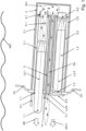
- the starting device of an embodiment according to the solution is shown in a side view.
- the starting device comprises two ramps 3.1, 3.2 arranged one above the other, each in the form of a cylindrical tube and each extending along a longitudinal axis La.1 or La.2 of the ramp.
- the two parallel longitudinal axes La.1, La.2 of the two ramps 3.1, 3.2 lie in the plane of the drawing 1 . It is possible that further ramps of the starting device are arranged in front of or behind the ramps 3.1, 3.2.
- the direction of travel of the watercraft is perpendicular or oblique to the plane of the drawing 1 .
- Each ramp 3.1, 3.2 is capable of receiving a canister 2.1, 2.2 with an underwater rocket 1.1, 1.2. It is possible for an adapter to be arranged inside a ramp 3.1, 3.2, so that the same ramp 3.1, 3.2 can successively accommodate objects with different diameters. It is also possible that an adapter is arranged in the interior of a canister 2.1, 2.2, so that several examples of identical canisters 2.1, 2.2 can be used for underwater rockets with different diameters.
- each ramp 3.1, 3.2 has a muzzle flap 6.1, 6.2, which is opened before the underwater rocket 1.1, 1.2 is launched.
- the ramp 3.1, 3.2 is filled with water, so that there is no pressure difference between the ramp 3.1, 3.2 and the surrounding water.
- the casing of the underwater rocket 1.1, 1.2 is able to withstand the surrounding water pressure.
- a membrane can also be provided at the outer end of a ramp 3.1, 3.2, which is pierced by the head of the underwater rocket 1.1, 1.2 when it is launched.
- the ramps 3.1, 3.2 are movably attached to the outer hull of the submarine. Before the underwater rockets 1.1, 1.2 are launched, the ramps 3.1, 3.2 are in a hydrodynamically favorable position in which they cause as little water resistance as possible. Before an underwater missile 1.1, 1.2 is launched, a ramp actuator (not shown) pivots the ramps 3.1, 3.2 into one desired direction towards the target. It is also possible that the ramps 3.1, 3.2 are permanently mounted on the outer shell, for example perpendicularly or at an angle to the direction of travel. In another embodiment, each ramp 3.1, 3.2 is embedded in a torpedo tube of the submarine.
- Each underwater rocket 1.1, 1.2 includes a rocket engine and several stabilizing fins.
- the rocket engine is able to eject a propellant, which moves the underwater rocket 1.1, 1.2 through the water when used underwater.
- the stabilizing fins stabilize the movement of the underwater missile 1.1, 1.2 through the water.
- An underwater rocket 1.1, 1.2 is transported to the watercraft in a round-cylindrical canister 2.1, 2.2.
- the canister 2.1, 2.2 with the underwater rocket 1.1, 1.2 is inserted into a ramp 3.1, 3.2 and remains ready for use in this ramp 3.1, 3.2 while the watercraft with the starting device according to the solution performs a specified task.
- Each canister 2.1, 2.2 has a front membrane 7.1, 7.2 and a rear membrane 8.1, 8.2.
- the terms "front” and “rear” refer to the direction of travel of the underwater missile 1.1, 1.2 out of the canister 2.1, 2.2.
- the canister 2.1, 2.2 surrounds the underwater missile 1.1, 1.2 in a watertight and airtight manner.
- the space in the canister 2.1, 2.2 around the underwater missile 1.1, 1.2 is filled with a fluid, preferably an inert fluid.
- a sealing plug 13 at the rear of the rocket engine of the underwater rocket 1.1 prevents fluid from entering the interior of the engine before the engine is activated.
- the canister 2.1, 2.2 need not necessarily be able to withstand the pressure of the surrounding water or the pressure of the ejected propellant Tr.1. Rather, before the underwater rocket 1.1, 1.2 is launched, depending on the embodiment, the ramp 3.1, 3.2 and/or the shell of the underwater rocket 1.1, 1.2 absorbs this water pressure.
- a drainage channel is let into the interior of the canister 2.1, 2.2, which extends parallel to the longitudinal axis of the ramp La.1, La.2 and ejects Directs propellant, exhaust gases and fluid and facilitates their outflow from the canister 2.1, 2.2.
- the drainage channel also makes it easier to fill the canister 2.1, 2.2 with a fluid.
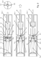
- FIG. 2 shows an example of a locking device that holds the underwater rocket 1.1 in the canister 2.1 and prevents the underwater rocket 1.1 from moving relative to the canister 2.1 while the watercraft is in motion and before launch, and therefore possibly from tilting.
- Two claws 9.1 and 9.2 engage in corresponding recesses on the rear of the underwater rocket 1.1 from two sides.
- the claw 9.1 is rotatably mounted about an axis of rotation D.1, the claw 9.2 about an axis of rotation D.2.
- the axes of rotation D.1 and D.2 are perpendicular to the plane of the drawing 2 and are preferably supported on the wall of the canister 2.1.
- These two claws 9.1, 9.2 are connected to a ram 10 via an articulated connection 11.
- the ram 10 can be linearly displaced along the longitudinal axis La.1 of the ramp.
- the tappet 10 is surrounded by a chamber Km.1 which is filled with a fluid which is under overpressure.
- a closing unit 12 closes this chamber Km.1. It is possible that three or four claws from three or four sides engage in corresponding recesses of the underwater missile 1.1, which is shown in the cross-sectional view in 2 is indicated on the right.
- the plunger 10 In order to release the locking of the underwater rocket 1.1 in the canister 2.1, the plunger 10 is pulled backwards, i.e. away from the canister 2.1 with the underwater rocket 1.1 (in 2 To the right). This also pulls the capping unit 12 backwards and the pressurized fluid exits the chamber Km.1, moving the ram 10 backwards and holding it in the retracted position.
- the conical shape of the closure unit 12 reinforces the linear movement of the ram 10 away from the canister 2.1.
- the linear movement of the ram 10 causes the articulation 11 to change from a T-shape to a Y-shape.
- the two points at which the connection 11 is connected to the two claws 9.1 and 9.2 are moved towards one another.
- the ignition of the engine Tw.1 of the underwater rocket 1.1 is blocked as long as the locking device with the claws 9.1, 9.2 keeps the underwater rocket 1.1 in the canister 2.1.
- a position sensor 16 for example a contact switch, generates a signal when the connection 11 hits the position sensor 16 while moving away from the canister 2.1. This event means that the locking device (claws 9.1, 9.2, plunger 10, connection 11) is in the release position.
- the blocking of the ignition of the engine Tw.1 is lifted and the engine of the underwater missile 1.1 can be ignited and thus activated.
- the canister 2.1 is electrically connected to a trigger device (not shown) outside the ramp 3.1, which fires the engine Tw.1.
- the sealing plug 13 at the rear of the engine Tw.1 of the underwater rocket 1.1 is ejected from the canister 2.1 through the open rear membrane 8.1.
- the chamber Km is surrounded by a wall 4 which can withstand the heat and the mechanical impulse of the expelled propellant Tr.1.
- the wall 4 contributes to the fact that no propellant Tr.1 can get into the interior of the watercraft.
- propellant Tr.1 is ejected through the membrane 8.1, and the rear membrane 8.2 of the second canister 2.2 is closed and can also withstand the propellant Tr.1. Therefore, the ejected propellant Tr.1 can only escape from the chamber Km through a channel Ka.
- This channel Ka extends along a longitudinal axis La.K and is surrounded by a wall 5, which can also withstand the heat and the mechanical impulse of the propellant Tr.1.
- the longitudinal axis La.K of the channel Ka is preferably not arranged horizontally, but slightly upwards, which is shown in 1 is implied. Therefore, the wall 4 around the chamber K and the wall 5 around the channel Ka direct the ejected propellant Tr.1 to an outlet A, which is embedded flush in the vehicle shell Fh.
- This outlet A is closed by a flap 14 or membrane.
- the diverted propellant Tr.1 opens this flap 14 or membrane.
- An actuator for the flap 14 is therefore not required.
- the outlet A is closed by a closure flap with a predetermined breaking point. The ejection of the propellant Tr.1 from the channel Ka causes this closure flap to break at the predetermined breaking point, the fragments are ejected and then the outlet A is opened.
- the ejected propellant Tm.1 opens the flap 14 in any case.
- the ejected propellant Tm.1 only opens the flap 14 when the pressure exerted by the propellant Tm.1 from the inside on the flap 14 exercises is above a predetermined limit. As long as the flap 14 is still closed, the pressure of the ejected propellant Tm.1 contributes to ejecting the underwater missile 1.1. At the same time, the desired safety effect is ensured, especially when the underwater missile 1.1 does not leave the ramp 3.1.
- the propellant Tr.1 together with the fluid from the canister 2.1, exhaust gases and evaporated water is ejected outwards through the opened outlet A in an outlet direction AR.T.
- the desired effect that the propellant Tr.1 is ejected to the outside also occurs when the underwater rocket 1.1 is jammed in the canister 2.1 or in the ramp 3.1 and therefore does not leave the ramp 3.1.
- all the propellant Tr.1 of the underwater rocket 1.1 is discharged to the outside through the chamber Km, the channel Ka and the outlet A, without entering the interior of the watercraft.
- the channel Ka rises slightly. Because of this, and because the propellant Tr.1 is lighter than water, all the propellant Tr.1 ejected into the chamber Km and entering the passage Ka exits the passage Ka quickly. No exhausted gas accumulates in the channel Ka. This prevents the watercraft from leaving a trail of bubbles due to propellant or exhaust gases gradually leaking from the channel Ka. This effect is particularly undesirable when the watercraft is an underwater vehicle on a diving trip.
- the chamber Km with the wall 4 and the channel Ka with the wall 5 and the outlet A are assigned to two adjacent ramps 3.1 and 3.2 and belong to a propellant deflection unit.
- one deflection device for the propellant is assigned to two adjacent ramps.
- This configuration makes it possible to save space, because fewer chambers and channels are required than the starting device comprises ramps.
- An alternative configuration is also possible, in which each ramp is assigned its own propellant deflection unit.
- the design with its own propellant deflection unit eliminates the need for the rear membrane 8.1, 8.2 of a canister 2.1, 2.2 to be able to withstand the ejected propellant of another underwater rocket.
- the channel Ka extends parallel to the longitudinal axis La.1, La.2 of a ramp 3.1, 3.2.
- the propellant Tr.1 is ejected parallel to the travel of the underwater rocket 1.1 and with a lateral offset.
- the propellant deflection unit thus deflects the propellant Tr.1 by 180°.
- the second ramp 3.2, the second canister 2.2 and the second underwater rocket 1.2 are in 3 and 4 Not shown.
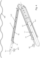
- 3 shows an alternative embodiment in a plan view from above, 4 in a side view a further alternative embodiment.
- the watercraft is traveling in a direction FR (in 3 in the drawing plane and from bottom to top, in 4 perpendicular or oblique to the plane of the drawing).
- the longitudinal axis La.1 of the ramp 1.1 and the longitudinal axis La.K of the channel Ka also lie in the planes of the drawing 3 and 4 .
- Situations shown are produced at least when starting the underwater running body 1.1. It is possible that a ramp actuator (not shown) has previously pivoted the ramp 1.1 into the firing position shown.
- the longitudinal axis La.K of the channel Ka is perpendicular to the direction of travel FR, the longitudinal axis La.1 of the ramp 3.1 at an angle to the direction of travel FR.
- the ejection direction AR of the underwater rocket 1.1 thus points obliquely forward.
- the deflection angle is preferably between 90° and 180° (inclusive).
- the ejection direction AR of the underwater rocket 1.1 obliquely downwards and is perpendicular or oblique to the travel direction FR of the watercraft.
- the longitudinal axis La.K of the channel Ka and thus the outlet direction AR.T of the propellant Tr.1 points obliquely upwards. This prevents propellant Tr.1 in the channel Ka accumulates and bubbles emerge, leaving the craft in a trail of bubbles.
- Reference sign 1.1 first underwater barrel body in the form of an underwater rocket includes the engine Tw.1, is included in the first canister 2.1 1.2 second underwater barrel body in the form of an underwater rocket is added to the second canister 2.2 2.1 first canister in which the first underwater rocket 1.1 is stored 2.2 second canister in which the second underwater missile 1.2 is stored 3.1 first ramp in which the first canister 2.1 is stored with the first underwater rocket 1.1 and which leads the first underwater rocket 1.1 at the start 3.2 second ramp, in which the second canister 2.2 is stored with the second underwater rocket 1.2 and which guides the second underwater rocket 1.2 at the start 4 Wall of the common chamber Km behind the two ramps 3.1 and 3.2 5 Wall of a canal Ka leading outwards from the chamber Km 6.1 Muzzle flap or membrane in front of the first ramp 3.1 is opened or pierced when the underwater rocket 1.1 is launched 6.2 Muzzle flap or membrane in front of the second ramp 3.2 is opened or pierced when the underwater rocket 1.2 is launched 7.1, 7.2 front membrane of the can
Landscapes
- Engineering & Computer Science (AREA)
- General Engineering & Computer Science (AREA)
- Ocean & Marine Engineering (AREA)
- Mechanical Engineering (AREA)
- Aviation & Aerospace Engineering (AREA)
- Toys (AREA)
- Output Control And Ontrol Of Special Type Engine (AREA)
- Catching Or Destruction (AREA)
Claims (15)
- Dispositif de lancement destiné à lancer un premier projectile sous-marin (1.1) depuis une plate-forme, notamment depuis un engin nautique,le premier projectile sous-marin (1.1) comprenant un premier mécanisme de propulsion (Tw.1) qui est adapté pour éjecter un agent de propulsion (Tr.1),le dispositif de lancement comprenant une première rampe (3.1) qui s'étend suivant un axe longitudinal (La.1) de la première rampe,la première rampe (3.1) étant conçue- pour enfermer et maintenir le premier projectile sous-marin (1.1) sous l'eau et- pour le diriger lors de son lancement en fonction de l'orientation de l'axe longitudinal (La.1) de la première rampe,le dispositif de lancement comprenant une unité de déviation d'agent de propulsion (4, 5, Km, Ka), le dispositif de lancement étant conçu pour activer le mécanisme de propulsion (Tw.1) ou pour permettre l'activation de celui-ci alors que le premier projectile sous-marin (1.1) est enfermé et maintenu sous l'eau dans la première rampe (3.1),la première rampe (3.1) étant conçue pour diriger l'agent de propulsion (Tr.1), éjecté du premier mécanisme de propulsion (Tw.1), vers l'unité de déviation d'agent de propulsion (4, 5, Km, Ka), et l'unité de déviation d'agent de propulsion (4, 5, Km, Ka) étant conçue pour dévier l'agent de propulsion éjecté (Tr.1) dans une direction de sortie (AR.T) qui s'étend perpendiculairement ou obliquement depuis la plate-forme, etle dispositif de lancement étant conçu de manière à ce que l'eau puisse pénétrer dans la ou chaque rampe (3.1, 3.2) ;caractérisé en ce quele dispositif de lancement comprend un premier volet de rampe (6.1) qui, à l'état fermé, obture la première rampe (3.1) vis-à-vis de l'eau environnante, le dispositif de lancement étant conçu pour ouvrir le premier volet de rampe (6.1) et permettre ainsi à l'eau de s'écouler jusque dans la première rampe (3.1) avant que le dispositif de lancement n'active le mécanisme de propulsion (Tw.1) du premier projectile sous-marin (1.1) .
- Dispositif de lancement selon la revendication 1,
caractérisé en ce que
l'unité de déviation d'agent de propulsion (4, 5, Km, Ka) est disposée de manière à ce que- la direction de sortie (AR.T) de l'agent de propulsion (Tr.1) soit parallèle à l'axe longitudinal (La.1) de la première rampe et- l'agent de propulsion dévié (Tr.1) sorte de l'unité de déviation d'agent de propulsion (4, 5, Km, Ka) à distance de l'axe longitudinal (La.1) de la première rampe. - Dispositif de lancement selon l'une des revendications précédentes,
caractérisé en ce quel'unité de déviation d'agent de propulsion (4, 5, Km, Ka) est disposée de manière à ce quela direction de sortie (AR.T) de l'agent de propulsion (Tr.1) forme un angle aigu (α) avec l'axe longitudinal (La.1) de la première rampe etl'unité de déviation d'agent de propulsion (4, 5, Km, Ka) dévie l'agent de propulsion éjecté (Tr.1) d'un angle obtus (180° - α). - Dispositif de lancement selon l'une des revendications précédentes,
caractérisé en ce quele dispositif de lancement comprend une deuxième rampe (3.2),la deuxième rampe (3.2) étant conçue pour enfermer, maintenir et diriger un deuxième projectile sous-marin (1.2) sous l'eau. - Dispositif de lancement selon la revendication 4, caractérisé en ce quele dispositif de lancement est conçu de manière à ce quela première rampe (3.1) et la deuxième rampe (3.2) dirigent un agent de propulsion (Tr.1), qui est éjecté du projectile sous-marin respectif (1.1, 1.2), jusque dans l'unité de déviation d'agent de propulsion (4, 5, Km, Ka).
- Dispositif de lancement selon l'une des revendications précédentes,
caractérisé en ce quele dispositif de lancement comprend un dispositif de verrouillage (9.1, 9.2, 10, 11, 12) qui peut être transféré d'un état de verrouillage à un état de libération, le dispositif de verrouillage (9.1, 9.2, 10, 11, 12) placé dans un état de verrouillage empêchant le mouvement du premier projectile sous-marin (1.1) dans la première rampe (3.1) par rapport à la première rampe (3.1),le dispositif de verrouillage (9.1, 9.2, 10, 11, 12) placé dans l'état de libération permettant au premier projectile sous-marin (1.1) de sortir de la première rampe (3.1) etle dispositif de lancement étant conçu pour empêcher l'activation du premier mécanisme de propulsion (Tw.1) tant que le dispositif de verrouillage (9.1, 9.2, 10, 11, 12) est dans l'état de verrouillage,notammentle dispositif de lancement comprenant un capteur de position (16) qui est conçu pour détecter le cas où le dispositif de verrouillage (9.1, 9.2, 10, 11, 12) est dans l'état de libération, le dispositif de lancement étant conçu, en réponse à la découverte que le dispositif de verrouillage (9.1, 9.2, 10, 11, 12) est dans l'état de libération, pour activer ou permettre l'activation du premier mécanisme de propulsion (Tw.1). - Dispositif de lancement selon l'une des revendications précédentes,
caractérisé en ce queun volet d'unité de déviation (14) sépare l'unité de déviation d'agent de propulsion (4, 5, Km, Ka) du fluide environnant,le volet d'unité de déviation (14) étant monté de manière à ce que l'agent de propulsion éjecté (Tr.1) soit apte à ouvrir le volet d'unité de déviation (14) et/ou à le faire éclater. - Dispositif de lancement selon la revendication 7, caractérisé en ce que
le volet d'unité de déviation (14) est conçu de manière à ce que l'agent de propulsion éjecté (Tr.1) n'ouvre ou ne fasse éclater le volet d'unité de déviation (14) que lorsque la pression exercée sur le volet d'unité de déviation (14) dépasse une limite spécifiée. - Dispositif de lancement selon l'une des revendications précédentes,
caractérisé en ce quele dispositif de lancement est disposé à bord d'un engin nautique etl'unité de déviation d'agent de propulsion (4, 5, Km, Ka) est disposée dans une position flottante standard de l'engin nautique de manière à ce que toute la trajectoire ou au moins le dernier tronçon (Ka) de la trajectoire de l'agent de propulsion éjecté (Tr.1) dans l'unité de déviation d'agent de propulsion (4, 5, Km, Ka) soit horizontale ou montante. - Dispositif de lancement selon l'une des revendications précédentes,
caractérisé en ce que
le dispositif de lancement comporte un actionneur de rampe qui est conçu pour faire pivoter la première rampe (3.1). - Engin nautique comprenant un dispositif de lancement selon l'une des revendications précédentes.
- Engin nautique selon la revendication 11, caractérisé en ce quel'engin nautique comprend au moins un canon,le dispositif de lancement étant inséré ou pouvant s'insérer dans le canon.
- Engin nautique selon la revendication 11 ou la revendication 12,
caractérisé en ce que
l'engin nautique est un engin sous-marin comprenant une coque épaisse, la coque épaisse enfermant une zone intérieure de manière étanche à la pression et le dispositif de lancement étant disposé à l'extérieur de la zone intérieure. - Engin nautique selon l'une des revendications 11 à 13,
caractérisé en ce quel'engin nautique est un engin de surface,le dispositif de lancement étant disposé de manière à se trouver sous la surface de l'eau (WO) lorsque l'engin de surface est dans la position flottante normale. - Procédé de lancement d'un premier projectile sous-marin (1.1) depuis une plate-forme, en particulier un engin nautique,le premier projectile sous-marin (1.1) comprenant un mécanisme de propulsion (Tw.1),pour effectuer le lancement un dispositif de lancement comprenant une première rampe (3.1) est utilisé qui s'étend suivant un axe longitudinal (La.1) de la première rampe, et le procédé comprenant les étapes suivantes :- la première rampe (3.1) enferme et maintient le premier projectile sous-marin (1.1) sous l'eau,- le mécanisme de propulsion (Tw.1) est activé,- le mécanisme de propulsion activé (Tw.1) éjecte un agent de propulsion (Tr.1) et- la première rampe (3.1) dirige le premier projectile sous-marin (1.1) lors de son lancement en fonction de l'orientation de l'axe longitudinal (La.1) de la première rampe,le dispositif de lancement comprenant une unité de déviation d'agent de propulsion (4, 5, Km, Ka),l'étape d'activation du mécanisme de propulsion (Tw.1) étant réalisée alors que le premier projectile sous-marin (1.1) est enfermé sous l'eau dans la première rampe (3.1) et maintenu par celle-ci, etle procédé comprenant les étapes supplémentaires suivantes :- la première rampe (3.1) du mécanisme de propulsion (Tw.1) dirige l'agent de propulsion éjecté (Tr.1) vers l'unité de déviation d'agent de propulsion (4, 5, Km, Ka) et- l'unité de déviation d'agent de propulsion (4, 5, Km, Ka) dévie l'agent de propulsion éjecté (Tr.1) dans une direction de sortie (AR.T) qui s'étend perpendiculairement ou obliquement depuis la plate-forme ;- le dispositif de lancement est obturé par un premier volet de rampe (6.1) vis-à-vis de l'eau environnante ;- le premier volet de rampe (6.1) est ouvert pour permettre à l'eau de s'écouler jusque dans la première rampe (3.1) avant que le dispositif de lancement n'active le mécanisme de propulsion (Tw.l) du premier projectile sous-marin (1.1).
Applications Claiming Priority (2)
| Application Number | Priority Date | Filing Date | Title |
|---|---|---|---|
| DE102018222490.0A DE102018222490A1 (de) | 2018-12-20 | 2018-12-20 | Vorrichtung und Verfahren zum Starten eines Unterwasser-Laufkörpers von einem Wasserfahrzeug aus |
| PCT/EP2019/083661 WO2020126502A1 (fr) | 2018-12-20 | 2019-12-04 | Dispositif et procédé de démarrage d'un corps mobile sous-marin à partir d'un véhicule marin |
Publications (2)
| Publication Number | Publication Date |
|---|---|
| EP3899409A1 EP3899409A1 (fr) | 2021-10-27 |
| EP3899409B1 true EP3899409B1 (fr) | 2023-03-08 |
Family
ID=68806765
Family Applications (1)
| Application Number | Title | Priority Date | Filing Date |
|---|---|---|---|
| EP19816290.1A Active EP3899409B1 (fr) | 2018-12-20 | 2019-12-04 | Dispositif et procédé de démarrage d'un corps mobile sous-marin à partir d'un véhicule marin |
Country Status (8)
| Country | Link |
|---|---|
| US (1) | US12017741B2 (fr) |
| EP (1) | EP3899409B1 (fr) |
| CA (1) | CA3119245C (fr) |
| DE (1) | DE102018222490A1 (fr) |
| ES (1) | ES2942472T3 (fr) |
| IL (1) | IL283102B2 (fr) |
| PL (1) | PL3899409T3 (fr) |
| WO (1) | WO2020126502A1 (fr) |
Families Citing this family (2)
| Publication number | Priority date | Publication date | Assignee | Title |
|---|---|---|---|---|
| CN114323556B (zh) * | 2021-12-29 | 2024-04-09 | 绵阳小巨人动力设备有限公司 | 应用在航行装置水下发射模拟系统中的水密隔断装置 |
| CN115742381B (zh) * | 2022-11-14 | 2023-09-05 | 江苏高倍智能装备有限公司 | 一种自动换胶的碳纤维拉挤用浸胶装置 |
Family Cites Families (21)
| Publication number | Priority date | Publication date | Assignee | Title |
|---|---|---|---|---|
| US4185538A (en) * | 1960-08-30 | 1980-01-29 | The United States Of America As Represented By The Secretary Of The Navy | Simplified air system for underwater rocket launching |
| FR2080080A5 (fr) * | 1970-02-23 | 1971-11-12 | Aerospatiale | |
| US4173919A (en) | 1977-12-12 | 1979-11-13 | General Dynamics Corporation | Two-way rocket plenum for combustion suppression |
| US4373420A (en) * | 1980-10-06 | 1983-02-15 | General Dynamics, Pomona Division | Combustion suppressor |
| GB2124741B (en) * | 1982-07-15 | 1986-01-08 | British Aerospace | Missile launcher |
| US5542333A (en) * | 1983-08-15 | 1996-08-06 | Hughes Missile Systems Company | Undersea vehicle ejection from capsules |
| US4934241A (en) * | 1987-11-12 | 1990-06-19 | General Dynamics Corp. Pomona Division | Rocket exhaust deflector |
| DE3814678C1 (fr) | 1988-04-30 | 1989-11-16 | Gerhard Klemm Maschinenfabrik Gmbh & Co, 4800 Bielefeld, De | |
| FR2649194B1 (fr) * | 1989-06-30 | 1994-05-13 | Aerospatiale Ste Nationale Indle | Dispositif d'ejection pour munition amphibie et propulseur independant en faisant partie |
| US5194688A (en) * | 1992-01-31 | 1993-03-16 | Hughes Missile Systems Company | Apparatus for limiting recirculation of rocket exhaust gases during missile launch |
| US5613460A (en) * | 1994-08-31 | 1997-03-25 | Newport News Shipbuilding And Dry Dock Company | Submersible vessel external load mounting system |
| US6079310A (en) * | 1996-12-05 | 2000-06-27 | The United States Of America As Represented By The Secretary Of The Navy | Portable launcher |
| US5837919A (en) * | 1996-12-05 | 1998-11-17 | The United States Of America As Represented By The Secretary Of The Navy | Portable launcher |
| FR2781771B1 (fr) * | 1998-08-03 | 2001-02-09 | Mediterranee Const Ind | Procede de calage d'un tube dans un logement tubulaire, notamment d'un tube lance-missile |
| US6427574B1 (en) * | 2001-04-11 | 2002-08-06 | The United States Of America As Represented By The Secretary Of The Navy | Submarine horizontal launch tactom capsule |
| US6526860B2 (en) * | 2001-06-19 | 2003-03-04 | Raytheon Company | Composite concentric launch canister |
| US6971300B2 (en) * | 2003-11-25 | 2005-12-06 | The United States Of America As Represented By The Secretary Of The Navy | Reloadable concentric canister launcher |
| FR2917493B1 (fr) * | 2007-06-13 | 2009-09-25 | Dcn Sa | Structure de mainten de conteneurs de missile d'un dispositif de lancement vertical de missiles |
| EP2107331B1 (fr) * | 2008-04-03 | 2013-07-31 | Whitehead Sistemi Subacquei S.p.A. | Dispositif de lancement de torpilles |
| GB201013253D0 (en) * | 2010-08-05 | 2011-07-27 | Bae Systems Plc | Unmanned underwater vehicle payload launch |
| DE102010048222A1 (de) * | 2010-10-12 | 2012-04-12 | Howaldtswerke-Deutsche Werft Gmbh | Unterseeboot |
-
2018
- 2018-12-20 DE DE102018222490.0A patent/DE102018222490A1/de not_active Ceased
-
2019
- 2019-12-04 IL IL283102A patent/IL283102B2/en unknown
- 2019-12-04 PL PL19816290.1T patent/PL3899409T3/pl unknown
- 2019-12-04 EP EP19816290.1A patent/EP3899409B1/fr active Active
- 2019-12-04 WO PCT/EP2019/083661 patent/WO2020126502A1/fr unknown
- 2019-12-04 US US17/293,143 patent/US12017741B2/en active Active
- 2019-12-04 CA CA3119245A patent/CA3119245C/fr active Active
- 2019-12-04 ES ES19816290T patent/ES2942472T3/es active Active
Also Published As
| Publication number | Publication date |
|---|---|
| IL283102A (en) | 2021-06-30 |
| PL3899409T3 (pl) | 2023-07-17 |
| CA3119245A1 (fr) | 2020-06-25 |
| ES2942472T3 (es) | 2023-06-01 |
| US12017741B2 (en) | 2024-06-25 |
| US20220009607A1 (en) | 2022-01-13 |
| WO2020126502A1 (fr) | 2020-06-25 |
| IL283102B1 (en) | 2024-03-01 |
| CA3119245C (fr) | 2023-08-22 |
| IL283102B2 (en) | 2024-07-01 |
| DE102018222490A1 (de) | 2020-06-25 |
| EP3899409A1 (fr) | 2021-10-27 |
Similar Documents
| Publication | Publication Date | Title |
|---|---|---|
| DE3152929C2 (de) | Antrieb für eine Waffe zum Einsatz gegen Unterwasserziele | |
| DE10212653B4 (de) | Lenkwaffen-Startvorrichtung und Verfahren zum Starten von Lenkwaffen | |
| EP3899409B1 (fr) | Dispositif et procédé de démarrage d'un corps mobile sous-marin à partir d'un véhicule marin | |
| DE3106446C2 (de) | Hydropulsantrieb für eine Waffe zum Einsatz unter Wasser | |
| DE69504064T2 (de) | Unterwasser waffen-hantierungs-und abschusssystem | |
| EP2602179A2 (fr) | Submersible | |
| DE3048666C2 (de) | Autarke Ausstoßeinrichtung für Lenkwaffen | |
| DE69024221T2 (de) | Raketenwaffensystem | |
| DE69003190T2 (de) | Ausstossvorrichtung für amphibische Munition sowie dazugehörender unabhängiger Antrieb. | |
| DE102005023825A1 (de) | Verfahren und Vorrichtung zur Verteidigung von Wasserfahrzeugen oder stationären Unterwassereinheiten gegen Angriffe aus dem Wasser oder der Luft | |
| EP3509941B1 (fr) | Module de canon | |
| DE69903489T2 (de) | Vorrichtung zum Abschuss eines Projektils aus einem Torpedorohr | |
| EP4051978B1 (fr) | Tube d'arme | |
| EP3788317B1 (fr) | Tube d'arme pour sous-marin | |
| DE3940583A1 (de) | Verfahren und vorrichtung zur vermeidung von abgangsstoerungen beim start eines schnellen kavitierenden unterwasser-laufkoerpers aus einer unterwasser-startvorrichtung | |
| EP4097416B1 (fr) | Canon d'arme pourvu d'une bague mobile de calibre | |
| EP2657126B1 (fr) | Submersible | |
| EP2581169A1 (fr) | Dispositif de dosage | |
| WO2009046798A1 (fr) | Procédé permettant d'amener des bouées sonar dans une zone cible et engin pour la mise en oeuvre dudit procédé | |
| DE2352384A1 (de) | System zum abschuss von flugkoerpern zu wasser | |
| DE3917481A1 (de) | Verbringungsfahrzeug fuer von einer wasseroberflaeche startende raketen | |
| DE405707C (de) | Vorrichtung zum Senden und Empfangen von Schallwellen | |
| EP3652063A1 (fr) | Véhicule sous-marin faisant pivoter une unité d'entraînement lors de l'immersion dans un milieu aquatique | |
| DE2057327A1 (de) | Strahltriebwerk fuer einen Flugkoerper | |
| DE102014002822A1 (de) | Verfahren zum Start eines Lenkflugkörpers und Flugkörpersystem |
Legal Events
| Date | Code | Title | Description |
|---|---|---|---|
| STAA | Information on the status of an ep patent application or granted ep patent |
Free format text: STATUS: UNKNOWN |
|
| STAA | Information on the status of an ep patent application or granted ep patent |
Free format text: STATUS: THE INTERNATIONAL PUBLICATION HAS BEEN MADE |
|
| PUAI | Public reference made under article 153(3) epc to a published international application that has entered the european phase |
Free format text: ORIGINAL CODE: 0009012 |
|
| STAA | Information on the status of an ep patent application or granted ep patent |
Free format text: STATUS: REQUEST FOR EXAMINATION WAS MADE |
|
| 17P | Request for examination filed |
Effective date: 20210720 |
|
| AK | Designated contracting states |
Kind code of ref document: A1 Designated state(s): AL AT BE BG CH CY CZ DE DK EE ES FI FR GB GR HR HU IE IS IT LI LT LU LV MC MK MT NL NO PL PT RO RS SE SI SK SM TR |
|
| DAV | Request for validation of the european patent (deleted) | ||
| DAX | Request for extension of the european patent (deleted) | ||
| GRAP | Despatch of communication of intention to grant a patent |
Free format text: ORIGINAL CODE: EPIDOSNIGR1 |
|
| STAA | Information on the status of an ep patent application or granted ep patent |
Free format text: STATUS: GRANT OF PATENT IS INTENDED |
|
| INTG | Intention to grant announced |
Effective date: 20221202 |
|
| GRAS | Grant fee paid |
Free format text: ORIGINAL CODE: EPIDOSNIGR3 |
|
| GRAA | (expected) grant |
Free format text: ORIGINAL CODE: 0009210 |
|
| STAA | Information on the status of an ep patent application or granted ep patent |
Free format text: STATUS: THE PATENT HAS BEEN GRANTED |
|
| AK | Designated contracting states |
Kind code of ref document: B1 Designated state(s): AL AT BE BG CH CY CZ DE DK EE ES FI FR GB GR HR HU IE IS IT LI LT LU LV MC MK MT NL NO PL PT RO RS SE SI SK SM TR |
|
| REG | Reference to a national code |
Ref country code: CH Ref legal event code: EP Ref country code: AT Ref legal event code: REF Ref document number: 1552836 Country of ref document: AT Kind code of ref document: T Effective date: 20230315 |
|
| REG | Reference to a national code |
Ref country code: DE Ref legal event code: R096 Ref document number: 502019007182 Country of ref document: DE |
|
| REG | Reference to a national code |
Ref country code: IE Ref legal event code: FG4D Free format text: LANGUAGE OF EP DOCUMENT: GERMAN |
|
| REG | Reference to a national code |
Ref country code: NL Ref legal event code: FP |
|
| REG | Reference to a national code |
Ref country code: SE Ref legal event code: TRGR |
|
| REG | Reference to a national code |
Ref country code: ES Ref legal event code: FG2A Ref document number: 2942472 Country of ref document: ES Kind code of ref document: T3 Effective date: 20230601 |
|
| REG | Reference to a national code |
Ref country code: NO Ref legal event code: T2 Effective date: 20230308 |
|
| REG | Reference to a national code |
Ref country code: LT Ref legal event code: MG9D |
|
| P01 | Opt-out of the competence of the unified patent court (upc) registered |
Effective date: 20230530 |
|
| PG25 | Lapsed in a contracting state [announced via postgrant information from national office to epo] |
Ref country code: RS Free format text: LAPSE BECAUSE OF FAILURE TO SUBMIT A TRANSLATION OF THE DESCRIPTION OR TO PAY THE FEE WITHIN THE PRESCRIBED TIME-LIMIT Effective date: 20230308 Ref country code: LV Free format text: LAPSE BECAUSE OF FAILURE TO SUBMIT A TRANSLATION OF THE DESCRIPTION OR TO PAY THE FEE WITHIN THE PRESCRIBED TIME-LIMIT Effective date: 20230308 Ref country code: LT Free format text: LAPSE BECAUSE OF FAILURE TO SUBMIT A TRANSLATION OF THE DESCRIPTION OR TO PAY THE FEE WITHIN THE PRESCRIBED TIME-LIMIT Effective date: 20230308 Ref country code: HR Free format text: LAPSE BECAUSE OF FAILURE TO SUBMIT A TRANSLATION OF THE DESCRIPTION OR TO PAY THE FEE WITHIN THE PRESCRIBED TIME-LIMIT Effective date: 20230308 |
|
| PG25 | Lapsed in a contracting state [announced via postgrant information from national office to epo] |
Ref country code: GR Free format text: LAPSE BECAUSE OF FAILURE TO SUBMIT A TRANSLATION OF THE DESCRIPTION OR TO PAY THE FEE WITHIN THE PRESCRIBED TIME-LIMIT Effective date: 20230609 Ref country code: FI Free format text: LAPSE BECAUSE OF FAILURE TO SUBMIT A TRANSLATION OF THE DESCRIPTION OR TO PAY THE FEE WITHIN THE PRESCRIBED TIME-LIMIT Effective date: 20230308 |
|
| PG25 | Lapsed in a contracting state [announced via postgrant information from national office to epo] |
Ref country code: SM Free format text: LAPSE BECAUSE OF FAILURE TO SUBMIT A TRANSLATION OF THE DESCRIPTION OR TO PAY THE FEE WITHIN THE PRESCRIBED TIME-LIMIT Effective date: 20230308 Ref country code: RO Free format text: LAPSE BECAUSE OF FAILURE TO SUBMIT A TRANSLATION OF THE DESCRIPTION OR TO PAY THE FEE WITHIN THE PRESCRIBED TIME-LIMIT Effective date: 20230308 Ref country code: PT Free format text: LAPSE BECAUSE OF FAILURE TO SUBMIT A TRANSLATION OF THE DESCRIPTION OR TO PAY THE FEE WITHIN THE PRESCRIBED TIME-LIMIT Effective date: 20230710 Ref country code: EE Free format text: LAPSE BECAUSE OF FAILURE TO SUBMIT A TRANSLATION OF THE DESCRIPTION OR TO PAY THE FEE WITHIN THE PRESCRIBED TIME-LIMIT Effective date: 20230308 Ref country code: CZ Free format text: LAPSE BECAUSE OF FAILURE TO SUBMIT A TRANSLATION OF THE DESCRIPTION OR TO PAY THE FEE WITHIN THE PRESCRIBED TIME-LIMIT Effective date: 20230308 |
|
| PG25 | Lapsed in a contracting state [announced via postgrant information from national office to epo] |
Ref country code: SK Free format text: LAPSE BECAUSE OF FAILURE TO SUBMIT A TRANSLATION OF THE DESCRIPTION OR TO PAY THE FEE WITHIN THE PRESCRIBED TIME-LIMIT Effective date: 20230308 Ref country code: IS Free format text: LAPSE BECAUSE OF FAILURE TO SUBMIT A TRANSLATION OF THE DESCRIPTION OR TO PAY THE FEE WITHIN THE PRESCRIBED TIME-LIMIT Effective date: 20230708 |
|
| REG | Reference to a national code |
Ref country code: DE Ref legal event code: R097 Ref document number: 502019007182 Country of ref document: DE |
|
| PLBE | No opposition filed within time limit |
Free format text: ORIGINAL CODE: 0009261 |
|
| STAA | Information on the status of an ep patent application or granted ep patent |
Free format text: STATUS: NO OPPOSITION FILED WITHIN TIME LIMIT |
|
| PGFP | Annual fee paid to national office [announced via postgrant information from national office to epo] |
Ref country code: GB Payment date: 20231220 Year of fee payment: 5 |
|
| PG25 | Lapsed in a contracting state [announced via postgrant information from national office to epo] |
Ref country code: SI Free format text: LAPSE BECAUSE OF FAILURE TO SUBMIT A TRANSLATION OF THE DESCRIPTION OR TO PAY THE FEE WITHIN THE PRESCRIBED TIME-LIMIT Effective date: 20230308 Ref country code: DK Free format text: LAPSE BECAUSE OF FAILURE TO SUBMIT A TRANSLATION OF THE DESCRIPTION OR TO PAY THE FEE WITHIN THE PRESCRIBED TIME-LIMIT Effective date: 20230308 |
|
| PGFP | Annual fee paid to national office [announced via postgrant information from national office to epo] |
Ref country code: TR Payment date: 20231130 Year of fee payment: 5 Ref country code: SE Payment date: 20231220 Year of fee payment: 5 Ref country code: NO Payment date: 20231222 Year of fee payment: 5 Ref country code: NL Payment date: 20231220 Year of fee payment: 5 Ref country code: IT Payment date: 20231228 Year of fee payment: 5 Ref country code: FR Payment date: 20231222 Year of fee payment: 5 Ref country code: DE Payment date: 20231214 Year of fee payment: 5 |
|
| 26N | No opposition filed |
Effective date: 20231211 |
|
| PGFP | Annual fee paid to national office [announced via postgrant information from national office to epo] |
Ref country code: PL Payment date: 20231124 Year of fee payment: 5 |
|
| PGFP | Annual fee paid to national office [announced via postgrant information from national office to epo] |
Ref country code: ES Payment date: 20240131 Year of fee payment: 5 |
|
| REG | Reference to a national code |
Ref country code: CH Ref legal event code: PL |
|
| PG25 | Lapsed in a contracting state [announced via postgrant information from national office to epo] |
Ref country code: LU Free format text: LAPSE BECAUSE OF NON-PAYMENT OF DUE FEES Effective date: 20231204 |
|
| PG25 | Lapsed in a contracting state [announced via postgrant information from national office to epo] |
Ref country code: MC Free format text: LAPSE BECAUSE OF FAILURE TO SUBMIT A TRANSLATION OF THE DESCRIPTION OR TO PAY THE FEE WITHIN THE PRESCRIBED TIME-LIMIT Effective date: 20230308 |
|
| REG | Reference to a national code |
Ref country code: BE Ref legal event code: MM Effective date: 20231231 |
|
| PG25 | Lapsed in a contracting state [announced via postgrant information from national office to epo] |
Ref country code: MC Free format text: LAPSE BECAUSE OF FAILURE TO SUBMIT A TRANSLATION OF THE DESCRIPTION OR TO PAY THE FEE WITHIN THE PRESCRIBED TIME-LIMIT Effective date: 20230308 Ref country code: LU Free format text: LAPSE BECAUSE OF NON-PAYMENT OF DUE FEES Effective date: 20231204 |