EP3899409B1 - Device and method for launching an underwater projectile from a watercraft - Google Patents
Device and method for launching an underwater projectile from a watercraft Download PDFInfo
- Publication number
- EP3899409B1 EP3899409B1 EP19816290.1A EP19816290A EP3899409B1 EP 3899409 B1 EP3899409 B1 EP 3899409B1 EP 19816290 A EP19816290 A EP 19816290A EP 3899409 B1 EP3899409 B1 EP 3899409B1
- Authority
- EP
- European Patent Office
- Prior art keywords
- ramp
- propellant
- launching device
- underwater
- deflection unit
- Prior art date
- Legal status (The legal status is an assumption and is not a legal conclusion. Google has not performed a legal analysis and makes no representation as to the accuracy of the status listed.)
- Active
Links
- 238000000034 method Methods 0.000 title claims description 7
- 239000003380 propellant Substances 0.000 claims description 144
- XLYOFNOQVPJJNP-UHFFFAOYSA-N water Substances O XLYOFNOQVPJJNP-UHFFFAOYSA-N 0.000 claims description 69
- 230000033001 locomotion Effects 0.000 claims description 18
- 239000012530 fluid Substances 0.000 claims description 11
- 230000004913 activation Effects 0.000 claims description 7
- 230000003213 activating effect Effects 0.000 claims description 3
- 230000001154 acute effect Effects 0.000 claims description 3
- 230000001419 dependent effect Effects 0.000 claims description 3
- 238000007667 floating Methods 0.000 claims description 3
- 230000001174 ascending effect Effects 0.000 claims description 2
- 238000001514 detection method Methods 0.000 claims 1
- 239000012528 membrane Substances 0.000 description 17
- 210000000078 claw Anatomy 0.000 description 16
- 239000007789 gas Substances 0.000 description 11
- 230000007246 mechanism Effects 0.000 description 9
- 238000013461 design Methods 0.000 description 6
- 235000015842 Hesperis Nutrition 0.000 description 5
- 235000012633 Iberis amara Nutrition 0.000 description 5
- 230000000694 effects Effects 0.000 description 5
- 239000000446 fuel Substances 0.000 description 3
- 238000007789 sealing Methods 0.000 description 3
- 230000008859 change Effects 0.000 description 2
- 238000002485 combustion reaction Methods 0.000 description 2
- 238000011161 development Methods 0.000 description 2
- 230000018109 developmental process Effects 0.000 description 2
- 230000009189 diving Effects 0.000 description 2
- 239000002360 explosive Substances 0.000 description 2
- 230000002349 favourable effect Effects 0.000 description 2
- 230000003993 interaction Effects 0.000 description 2
- 230000004048 modification Effects 0.000 description 2
- 238000012986 modification Methods 0.000 description 2
- 230000000087 stabilizing effect Effects 0.000 description 2
- 239000002352 surface water Substances 0.000 description 2
- 230000001133 acceleration Effects 0.000 description 1
- 230000004888 barrier function Effects 0.000 description 1
- 230000000903 blocking effect Effects 0.000 description 1
- 238000010276 construction Methods 0.000 description 1
- 230000002950 deficient Effects 0.000 description 1
- 238000010304 firing Methods 0.000 description 1
- 239000012634 fragment Substances 0.000 description 1
- 238000010438 heat treatment Methods 0.000 description 1
- 238000012423 maintenance Methods 0.000 description 1
- 230000000149 penetrating effect Effects 0.000 description 1
- 230000004044 response Effects 0.000 description 1
- 230000008054 signal transmission Effects 0.000 description 1
- 239000013589 supplement Substances 0.000 description 1
- 230000009182 swimming Effects 0.000 description 1
Images

Classifications
-
- B—PERFORMING OPERATIONS; TRANSPORTING
- B63—SHIPS OR OTHER WATERBORNE VESSELS; RELATED EQUIPMENT
- B63G—OFFENSIVE OR DEFENSIVE ARRANGEMENTS ON VESSELS; MINE-LAYING; MINE-SWEEPING; SUBMARINES; AIRCRAFT CARRIERS
- B63G8/00—Underwater vessels, e.g. submarines; Equipment specially adapted therefor
- B63G8/28—Arrangement of offensive or defensive equipment
- B63G8/32—Arrangement of offensive or defensive equipment of torpedo-launching means; of torpedo stores or handlers
-
- F—MECHANICAL ENGINEERING; LIGHTING; HEATING; WEAPONS; BLASTING
- F41—WEAPONS
- F41F—APPARATUS FOR LAUNCHING PROJECTILES OR MISSILES FROM BARRELS, e.g. CANNONS; LAUNCHERS FOR ROCKETS OR TORPEDOES; HARPOON GUNS
- F41F3/00—Rocket or torpedo launchers
- F41F3/04—Rocket or torpedo launchers for rockets
- F41F3/0413—Means for exhaust gas disposal, e.g. exhaust deflectors, gas evacuation systems
-
- F—MECHANICAL ENGINEERING; LIGHTING; HEATING; WEAPONS; BLASTING
- F41—WEAPONS
- F41F—APPARATUS FOR LAUNCHING PROJECTILES OR MISSILES FROM BARRELS, e.g. CANNONS; LAUNCHERS FOR ROCKETS OR TORPEDOES; HARPOON GUNS
- F41F3/00—Rocket or torpedo launchers
- F41F3/04—Rocket or torpedo launchers for rockets
- F41F3/07—Underwater launching-apparatus
-
- F—MECHANICAL ENGINEERING; LIGHTING; HEATING; WEAPONS; BLASTING
- F41—WEAPONS
- F41F—APPARATUS FOR LAUNCHING PROJECTILES OR MISSILES FROM BARRELS, e.g. CANNONS; LAUNCHERS FOR ROCKETS OR TORPEDOES; HARPOON GUNS
- F41F3/00—Rocket or torpedo launchers
- F41F3/08—Rocket or torpedo launchers for marine torpedoes
- F41F3/10—Rocket or torpedo launchers for marine torpedoes from below the surface of the water
Definitions
- the invention relates to a launching device for launching an underwater running body from a platform, in particular from a watercraft, and a method using such a launching device.
- Vertical launch pads for rockets are known from underwater vehicles and also from surface ships.
- the missile is loaded into the launcher in a canister and ejected from the canister vertically or at an angle, leaving the canister in the launch pad.
- US 5,837,919 A discloses a launcher having means for directing and concentrically distributing and scattering exhaust gases produced by internal combustion of an object, such as an object.
- B a missile generated, which can be operationally shot down from there.
- EP 2 003 417 A1 discloses a structure for supporting missile pods of a vertical missile launcher.
- US 4,173,919A discloses a system using a rocket chamber design shaped to reduce and control combustion therein.
- EP 2 107 331 A1 discloses an apparatus for launching a torpedo.
- the object of the invention is to provide a starting device with the features of the preamble of claim 1 and a method with the features of the preamble of claim 15, in which the starting device enables the underwater running body to be started under water and which is simpler in construction than known starting devices .
- the starting device is able to start an underwater running body from a watercraft or from another platform under water.
- the underwater running body to be launched includes an engine. This engine can be activated and ejects a propellant when activated.
- the ramp extends along a longitudinal axis of the ramp and is able to enclose and hold the underwater running body under water.
- the launcher is capable of activating the engine of the submersible while the submersible is enclosed and supported underwater by the ramp. After the underwater running body is launched, the ramp steers the launched underwater running body on a first part of its trajectory depending on the orientation of the ramp's longitudinal axis.
- the propellant deflection unit directs ejected propellant in an outlet direction.
- This outlet direction of the propellant points perpendicularly or obliquely from the platform away, on which the starting device is mounted and from which the underwater running body is started.
- An underwater running body within the meaning of the invention is an unmanned underwater vehicle which converts fuel into propellant, e.g. burns it, ejects the propellant produced and is moved through the water by the ejection of the propellant. It is possible that the underwater running body has an additional drive means.
- the underwater running body can operate autonomously or be remotely controlled, for example via a wire.
- the starting device is able to start an underwater running body with an engine.
- An underwater running body with an engine which ejects a propellant can in many cases achieve greater acceleration and reach a target under water more quickly than an underwater running body which is solely driven by at least one propeller. This is important in some applications, for example when the submersible is intended to neutralize an attacking torpedo before it reaches the platform, such as a surface vessel, or other target.
- the launch of the underwater running body using the launch device according to the solution does not depend at all or at least to a lesser extent than known launch devices on the water depth of the launch device at the moment of launch.
- the starting device is able to pick up and start the underwater running body, while the ramp of the starting device and the underwater running body are below the water surface.
- the target for the underwater barrel can also be located completely or at least partially below the water surface. It is possible to configure the underwater barrel for use exclusively under water. In this case, the movement of the underwater carriage can be controlled more easily than if the underwater carriage were to fly both through the water and through the air. In particular, the underwater carriage is prevented from changing its trajectory quickly and in a manner that is difficult or impossible to control, which can happen when the underwater carriage penetrates the water surface from the water or from the air.
- the starting device is able to activate the engine of the underwater running body while the underwater running body is still in the ramp and the ramp encloses and holds the underwater running body.
- the ramp guides the launched underwater running body on a first part of the trajectory until the underwater running body has reached a certain speed and thus kinetic energy and the risk is reduced that water currents etc. will throw the underwater running body off the path. These water currents can occur, for example, due to the movement of a platform, which carries the starting device according to the solution, through the water.
- the thruster is filled with a propellant and upon activation ejects generated propellant. The underwater running body is pushed out of the ramp by the ejection of the propellant.
- the thruster ejects the submersible from the ramp without the need for compressed air or a piston or other ejection mechanism to eject the submersible.
- a mechanism requires space and electrical and/or hydraulic and/or mechanical energy. Both are usually only available to a limited extent on board a platform, particularly if the platform is an underwater vehicle.
- an ejection mechanism often requires regular servicing and/or maintenance and there is a risk that this ejection mechanism will fail.
- a pneumatic circuit for a pneumatically operated ejection mechanism has the further disadvantage that gas bubbles can escape from a leak and rise to the water surface, which in many cases is undesirable. The invention thus leads to a starting device with a simpler mechanical structure and reduces the risk of gas bubbles escaping even before the start.
- the launcher is easier to mount onboard an existing platform.
- the starting device, together with the or each underwater running body, can often be accommodated in already existing torpedo tubes of a surface water vehicle or underwater vehicle that are arranged under water.
- An underwater barrel body is often delivered in a canister.
- the canister together with the underwater running body is inserted into the ramp.
- the engine is activated and ejects propellant, the underwater barrel exits the canister, which remains in the ramp. It is possible, but not necessary thanks to the invention, for an ejection mechanism to open or pierce the canister in order to eject the underwater barrel body.
- the underwater carriage in the ramp ejects propellant in an ejection direction that is usually parallel to the ramp's longitudinal axis and opposite to the direction in which the underwater carriage exits the ramp (actio equals reactio ).
- the underwater running body is displaced in a starting direction parallel to the longitudinal axis of the ramp and is then ejected from the ramp.
- the launching direction of the submersible body is typically away from the platform, and therefore the ejection direction of the propellant is towards the platform.
- the propellant deflection unit prevents this undesired event.
- a hazard for a crew member of the platform which includes the launch device with the ramp, and for the platform itself must not occur even if the underwater running body does not leave the ramp after the engine is activated due to a fault, but e.g. B. is stuck in the ramp or is otherwise held or if a flap of the ramp is not open.
- the underwater running body ejects propellant in the ramp until the The engine has run out of fuel. Therefore, a significantly larger amount of propellant is expelled in the ramp than in a clean launch. Thanks to the propellant diverter, despite this error, the ejected propellant is moved away from the platform, namely in the outlet direction that the propellant diverter determines. This feature prevents the dangerous and therefore undesirable event of the ejected propellant heating the ramp to the point of exploding or igniting propellant or a warhead of the underwater vehicle, or damaging the heated ramp or a vehicle hull.
- the launch device prefferably has a mechanism that shuts down the engine or deactivates a warhead if the underwater running body does not leave the ramp after the engine has been activated due to a fault.
- the propellant is ejected in the same direction as the underwater barrel body, but with a lateral offset and not from the ramp but from the propellant deflection unit.
- an impulse is exerted on the surrounding water in only one direction, namely on the one hand by the underwater running body and on the other hand by the ejected propellant. This means that turbulence and/or gas bubbles do not occur in two places far apart from each other in the water, which can be discovered and provide information about the issuing platform.
- this configuration enables a particularly compact and space-saving design.
- the entire starting device extends essentially along the longitudinal axis of the ramp and has only relatively small dimensions perpendicular to the longitudinal axis of the ramp. This is particularly important when the launcher is mounted onboard a submersible.
- the outlet direction of the propellant encloses an acute angle with the longitudinal axis of the ramp.
- An acute or obtuse angle preferably occurs between the outlet direction and the ejection direction of the underwater running body.
- the propellant deflection unit deflects the propellant through an obtuse angle.
- the deflection angle is preferably greater than 60°, particularly preferably greater than 120°.
- the distance between the launched underwater vehicle and the propellant which has left the propellant turning unit increases during movement of the underwater vehicle.
- an interaction between the propellant which has left the propellant deflection unit and the underwater running body is avoided with greater certainty. This interaction is undesirable in some situations, for example because the movement control of the underwater running body can be made more difficult or an active or passive sonar system of the underwater running body can deliver incorrect results.
- the starting device includes, in addition to the first ramp, a second ramp which extends along a second longitudinal axis of the ramp and is at a distance from the first longitudinal axis of the ramp.
- the two longitudinal axes of the ramp can be arranged parallel to one another or at an angle lock in.
- the second ramp is capable of enclosing, supporting and directing a second underwater carriage underwater.
- the launcher is able to launch two underwater running bodies simultaneously or one after the other without having to be reloaded onto a ramp in between.
- the same propellant deflection unit is used for at least two different ramps. This embodiment saves space compared to an embodiment in which each ramp is assigned its own propellant deflection unit.
- first group with at least two ramps to be assigned a first propellant deflection unit and for a second group with at least one further ramp to be assigned a second propellant deflection unit.
- the starting device preferably includes a locking device which is assigned to the first ramp. It is possible that a further locking device of the same type is assigned to the second ramp.
- the or each locking device can be switched into a locking state and into a release state, preferably independently of any other locking device.
- the associated locking device in the locked state prevents the locked underwater running body in the ramp from moving relative to the ramp, in particular from tilting or slipping out of the ramp.
- the detent in the released state allows the underwater carriage to exit the ramp.
- the starting device not only prevents or blocks movement of the underwater running body, but also activation of the engine.
- the engine can only be activated when the locking device has been transferred to the release state.
- the locking device prevents the underwater running body from performing an undesired movement relative to the ramp before the engine is activated. Such undesired movement could damage the underwater carriage and/or the ramp or result in the underwater carriage not being able to leave the ramp.
- the engine can only be activated and the underwater running body can only leave the ramp when the locking device is in the released state. Thanks to this configuration, the undesired event that the drive mechanism of the underwater running body is activated, although the locking device is still in the locking state, is prevented. This undesired event can result in the underwater drive body being stuck in the ramp with the engine activated, for example because ejected propellant prevents the locking device from being placed in the release state.
- the starting device includes a position sensor.
- This position sensor can positively detect the event that the locking device is in the release state. "Detect positive" means that the position sensor generates a signal when it detects the event.
- the starting device is able to activate the engine after the position sensor has detected that the locking device is in the unlocked state.
- the engine is activated in response to the event that the locking device is in the release state. Activation of the first thruster may also be inhibited until the position sensor detects this event.
- This refinement with the position sensor makes it possible to meet a legal requirement, namely that an engine may only be activated when a specific safety-related event has been physically discovered.
- the event that the position sensor discovers that the locking device is in the release state and has generated a corresponding signal is used as the safety-relevant event. This refinement thus shows a way of meeting a legal requirement for activating an engine.
- the position sensor then preferably sends a corresponding signal when it has discovered the release state.
- the engine can only be activated if the release signal is present. In this way, if the position sensor or a control unit of the starting device fails or the signal transmission is interrupted, a safe state is ensured, namely that the engine is not activated.
- water can penetrate into the first ramp and/or into the second ramp, and this is desirable.
- a ramp flap preferably then closes the ramp from surrounding water when the ramp flap is in a closed state. In an open condition, the ramp hatch allows water to enter the ramp.
- the launcher is able to open the ramp flap and thereby allow water to flow into the ramp.
- the launcher opens the ramp door before the launcher activates the underwater vehicle's engine.
- the submersible body is surrounded by water in the ramp when its engine is fired. This makes it easier to control the trajectory of the underwater carriage compared to one Configuration in which the launched underwater running body suddenly hits water.
- the starting device starts the underwater barrel under water.
- the outlet opening of the propellant deflection unit can be located above or below the water surface.
- the ejected and deflected propellant can thus be ejected above or below the water surface.
- a deflection unit flap separates the propellant deflection unit from the surrounding fluid, in the case of an ejection of propellant below the water surface from the surrounding water, as long as the deflection unit flap is closed.
- an actuator is able to open this deflection unit flap.
- ejected and deflected propellant is able to open the deflection unit flap or cause it to burst. This preferred embodiment saves an actuator for the deflection unit flap.
- the deflected propellant is only able to open the deflection unit flap when the pressure exerted by the propellant on the flap exceeds a predetermined limit.
- This barrier can be dimensioned in such a way that the flap remains closed in the event of a faultless launch of the underwater vehicle and the pressure of the propellant contributes in addition to the recoil to ejecting the underwater vehicle. Only if the submersible body does not leave the ramp due to a fault does the pressure of the ejected propellant open the flap.
- the deflection unit flap prevents the surrounding fluid, in particular water, from penetrating into the propellant deflection unit. Furthermore, when the platform is a watercraft, it allows the diverter unit flap to have a streamlined shape when closed of the watercraft contributes. This reduces the risk of water turbulence occurring at an outlet opening of the propellant deflection unit.
- the ejected propellant is capable of opening the diverter door, it is not necessary to open the diverter door by means of an actuator. Such an actuator may be defective. In addition, in some applications it may take too much time to open the diverter unit flap using an actuator. Opening with the help of the propellant works quickly and without an actuator.
- the starting device according to the solution is mounted on board a watercraft.
- the propellant deflection unit is preferably mounted on board this watercraft in such a way that the following is effected in a standard floating position of the watercraft: the entire trajectory or at least the last stretch of the trajectory of propellant, which is directed into the propellant deflection unit and through the propellant - Deflection unit is moved is horizontal or ascending.
- the starting device includes a ramp actuator.
- This ramp actuator is able to pivot the ramp. In particular, this makes it possible to change the ejection direction in which the underwater running body is ejected from the ramp.
- a pivoting of the ramp has the effect that the outlet direction in which propellant is discharged from the propellant deflection unit is also changed.
- the ramp actuator is capable of pivoting the ramp and thereby changing the orientation of the ramp's longitudinal axis relative to the platform. This allows the underwater running body to be launched in a desired one of several possible directions. In the case of a watercraft as the platform, the underwater ramp is allowed to be in a hydrodynamically favorable position relative to the direction of travel of the watercraft before the underwater vehicle is launched in the ramp. The ramp therefore causes relatively little water resistance while the watercraft is moving.
- the ramp actuator pivots the ramp relative to the vehicle hull to a desired position for launch. For example, the ramp actuator pivots the first ramp(s) from a cruise position to a launch position before the engine is activated.
- the starting device according to the solution is a component of a platform, in particular a watercraft, or can be mounted on board a platform at least temporarily. Thanks in particular to the propellant deflection unit, it is often possible with little effort to retrofit a starting device according to the solution on board a platform or to supplement an existing starting device and thereby increase operational reliability.
- this watercraft includes a weapon tube, for example a torpedo tube or a tube to eject mines or containers or underwater swimming aids.
- the entire starting device or at least the ramp with the underwater barrel body and the optional locking device is arranged in this weapon barrel. It is possible that an adapter is inserted into the inside of the gun barrel in order to bridge the distance between the larger inside diameter of the gun barrel and the smaller outside diameter of the ramp. It is even possible that two ramps of a starting device according to the solution are inserted into the interior of the same weapon barrel with the aid of an adapter. It is also possible to mount the starting device on an outer hull of the watercraft so that the launching device is permanently surrounded by water and can be quickly prepared for launching an underwater running body.
- the launcher platform may be a manned or unmanned surface vehicle or underwater vehicle. This watercraft can have its own drive or be designed without its own drive.
- the platform can also be stationary on the water, for example on board an oil rig or a buoy, or mounted on land and there on a shore, for example to protect a harbor from attack.
- the invention is used in a starting device which is arranged on board an underwater vehicle, for example on board a manned submarine.
- the underwater vehicle has a vehicle hull Fh, for example a pressure hull or an outer hull.
- the starting device according to the solution is embedded flush in this vehicle shell Fh.
- the starting device according to the solution is preferably arranged completely outside the pressure hull, ie between the pressure hull and the outer shell, and is exposed to the pressure of the surrounding water during a diving trip.
- the invention can be used on board a surface vehicle as well.
- the starting device is mounted on an area of the vehicle hull Fh of the surface water vehicle, which area remains permanently below the water surface during use.
- the underwater missile remains under water throughout the journey.
- the launch device is capable of launching at least one underwater rocket, in the exemplary embodiment several underwater rockets, below the water surface WO.
- An underwater rocket is understood to mean a running body that is designed for use under water and has a rocket engine, i.e. a drive that can be activated and, after activation, converts a fuel into a propellant, e.g. burns the propellant produced ejects and thereby moves the barrel body in the opposite direction to the ejection direction of the propellant.
- the underwater missile remains below the water surface WO throughout the entire operation and can withstand the water pressure down to a predetermined maximum water depth.
- the underwater missile may have a cruise engine plus a launch engine used only to launch the underwater missile, or a single engine for the entire trip.
- the term "rocket engine” is used for that engine which causes the underwater rocket to be launched from the ramp. As a rule, an underwater missile accelerates faster in the water than a torpedo, which is propelled by at least one propeller.
- Each underwater missile also includes a sonar system, which operates actively and/or passively, and a warhead with an explosive charge and is designed to use the sonar system to locate another underwater vehicle, to drive towards it and, by detonating the explosive charge, to locate it Destroy underwater carriage before the underwater carriage reaches the watercraft with the launcher or another watercraft.
- a sonar system which operates actively and/or passively, and a warhead with an explosive charge and is designed to use the sonar system to locate another underwater vehicle, to drive towards it and, by detonating the explosive charge, to locate it Destroy underwater carriage before the underwater carriage reaches the watercraft with the launcher or another watercraft.
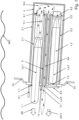
- the starting device of an embodiment according to the solution is shown in a side view.
- the starting device comprises two ramps 3.1, 3.2 arranged one above the other, each in the form of a cylindrical tube and each extending along a longitudinal axis La.1 or La.2 of the ramp.
- the two parallel longitudinal axes La.1, La.2 of the two ramps 3.1, 3.2 lie in the plane of the drawing 1 . It is possible that further ramps of the starting device are arranged in front of or behind the ramps 3.1, 3.2.
- the direction of travel of the watercraft is perpendicular or oblique to the plane of the drawing 1 .
- Each ramp 3.1, 3.2 is capable of receiving a canister 2.1, 2.2 with an underwater rocket 1.1, 1.2. It is possible for an adapter to be arranged inside a ramp 3.1, 3.2, so that the same ramp 3.1, 3.2 can successively accommodate objects with different diameters. It is also possible that an adapter is arranged in the interior of a canister 2.1, 2.2, so that several examples of identical canisters 2.1, 2.2 can be used for underwater rockets with different diameters.
- each ramp 3.1, 3.2 has a muzzle flap 6.1, 6.2, which is opened before the underwater rocket 1.1, 1.2 is launched.
- the ramp 3.1, 3.2 is filled with water, so that there is no pressure difference between the ramp 3.1, 3.2 and the surrounding water.
- the casing of the underwater rocket 1.1, 1.2 is able to withstand the surrounding water pressure.
- a membrane can also be provided at the outer end of a ramp 3.1, 3.2, which is pierced by the head of the underwater rocket 1.1, 1.2 when it is launched.
- the ramps 3.1, 3.2 are movably attached to the outer hull of the submarine. Before the underwater rockets 1.1, 1.2 are launched, the ramps 3.1, 3.2 are in a hydrodynamically favorable position in which they cause as little water resistance as possible. Before an underwater missile 1.1, 1.2 is launched, a ramp actuator (not shown) pivots the ramps 3.1, 3.2 into one desired direction towards the target. It is also possible that the ramps 3.1, 3.2 are permanently mounted on the outer shell, for example perpendicularly or at an angle to the direction of travel. In another embodiment, each ramp 3.1, 3.2 is embedded in a torpedo tube of the submarine.
- Each underwater rocket 1.1, 1.2 includes a rocket engine and several stabilizing fins.
- the rocket engine is able to eject a propellant, which moves the underwater rocket 1.1, 1.2 through the water when used underwater.
- the stabilizing fins stabilize the movement of the underwater missile 1.1, 1.2 through the water.
- An underwater rocket 1.1, 1.2 is transported to the watercraft in a round-cylindrical canister 2.1, 2.2.
- the canister 2.1, 2.2 with the underwater rocket 1.1, 1.2 is inserted into a ramp 3.1, 3.2 and remains ready for use in this ramp 3.1, 3.2 while the watercraft with the starting device according to the solution performs a specified task.
- Each canister 2.1, 2.2 has a front membrane 7.1, 7.2 and a rear membrane 8.1, 8.2.
- the terms "front” and “rear” refer to the direction of travel of the underwater missile 1.1, 1.2 out of the canister 2.1, 2.2.
- the canister 2.1, 2.2 surrounds the underwater missile 1.1, 1.2 in a watertight and airtight manner.
- the space in the canister 2.1, 2.2 around the underwater missile 1.1, 1.2 is filled with a fluid, preferably an inert fluid.
- a sealing plug 13 at the rear of the rocket engine of the underwater rocket 1.1 prevents fluid from entering the interior of the engine before the engine is activated.
- the canister 2.1, 2.2 need not necessarily be able to withstand the pressure of the surrounding water or the pressure of the ejected propellant Tr.1. Rather, before the underwater rocket 1.1, 1.2 is launched, depending on the embodiment, the ramp 3.1, 3.2 and/or the shell of the underwater rocket 1.1, 1.2 absorbs this water pressure.
- a drainage channel is let into the interior of the canister 2.1, 2.2, which extends parallel to the longitudinal axis of the ramp La.1, La.2 and ejects Directs propellant, exhaust gases and fluid and facilitates their outflow from the canister 2.1, 2.2.
- the drainage channel also makes it easier to fill the canister 2.1, 2.2 with a fluid.
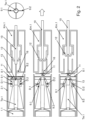
- FIG. 2 shows an example of a locking device that holds the underwater rocket 1.1 in the canister 2.1 and prevents the underwater rocket 1.1 from moving relative to the canister 2.1 while the watercraft is in motion and before launch, and therefore possibly from tilting.
- Two claws 9.1 and 9.2 engage in corresponding recesses on the rear of the underwater rocket 1.1 from two sides.
- the claw 9.1 is rotatably mounted about an axis of rotation D.1, the claw 9.2 about an axis of rotation D.2.
- the axes of rotation D.1 and D.2 are perpendicular to the plane of the drawing 2 and are preferably supported on the wall of the canister 2.1.
- These two claws 9.1, 9.2 are connected to a ram 10 via an articulated connection 11.
- the ram 10 can be linearly displaced along the longitudinal axis La.1 of the ramp.
- the tappet 10 is surrounded by a chamber Km.1 which is filled with a fluid which is under overpressure.
- a closing unit 12 closes this chamber Km.1. It is possible that three or four claws from three or four sides engage in corresponding recesses of the underwater missile 1.1, which is shown in the cross-sectional view in 2 is indicated on the right.
- the plunger 10 In order to release the locking of the underwater rocket 1.1 in the canister 2.1, the plunger 10 is pulled backwards, i.e. away from the canister 2.1 with the underwater rocket 1.1 (in 2 To the right). This also pulls the capping unit 12 backwards and the pressurized fluid exits the chamber Km.1, moving the ram 10 backwards and holding it in the retracted position.
- the conical shape of the closure unit 12 reinforces the linear movement of the ram 10 away from the canister 2.1.
- the linear movement of the ram 10 causes the articulation 11 to change from a T-shape to a Y-shape.
- the two points at which the connection 11 is connected to the two claws 9.1 and 9.2 are moved towards one another.
- the ignition of the engine Tw.1 of the underwater rocket 1.1 is blocked as long as the locking device with the claws 9.1, 9.2 keeps the underwater rocket 1.1 in the canister 2.1.
- a position sensor 16 for example a contact switch, generates a signal when the connection 11 hits the position sensor 16 while moving away from the canister 2.1. This event means that the locking device (claws 9.1, 9.2, plunger 10, connection 11) is in the release position.
- the blocking of the ignition of the engine Tw.1 is lifted and the engine of the underwater missile 1.1 can be ignited and thus activated.
- the canister 2.1 is electrically connected to a trigger device (not shown) outside the ramp 3.1, which fires the engine Tw.1.
- the sealing plug 13 at the rear of the engine Tw.1 of the underwater rocket 1.1 is ejected from the canister 2.1 through the open rear membrane 8.1.
- the chamber Km is surrounded by a wall 4 which can withstand the heat and the mechanical impulse of the expelled propellant Tr.1.
- the wall 4 contributes to the fact that no propellant Tr.1 can get into the interior of the watercraft.
- propellant Tr.1 is ejected through the membrane 8.1, and the rear membrane 8.2 of the second canister 2.2 is closed and can also withstand the propellant Tr.1. Therefore, the ejected propellant Tr.1 can only escape from the chamber Km through a channel Ka.
- This channel Ka extends along a longitudinal axis La.K and is surrounded by a wall 5, which can also withstand the heat and the mechanical impulse of the propellant Tr.1.
- the longitudinal axis La.K of the channel Ka is preferably not arranged horizontally, but slightly upwards, which is shown in 1 is implied. Therefore, the wall 4 around the chamber K and the wall 5 around the channel Ka direct the ejected propellant Tr.1 to an outlet A, which is embedded flush in the vehicle shell Fh.
- This outlet A is closed by a flap 14 or membrane.
- the diverted propellant Tr.1 opens this flap 14 or membrane.
- An actuator for the flap 14 is therefore not required.
- the outlet A is closed by a closure flap with a predetermined breaking point. The ejection of the propellant Tr.1 from the channel Ka causes this closure flap to break at the predetermined breaking point, the fragments are ejected and then the outlet A is opened.
- the ejected propellant Tm.1 opens the flap 14 in any case.
- the ejected propellant Tm.1 only opens the flap 14 when the pressure exerted by the propellant Tm.1 from the inside on the flap 14 exercises is above a predetermined limit. As long as the flap 14 is still closed, the pressure of the ejected propellant Tm.1 contributes to ejecting the underwater missile 1.1. At the same time, the desired safety effect is ensured, especially when the underwater missile 1.1 does not leave the ramp 3.1.
- the propellant Tr.1 together with the fluid from the canister 2.1, exhaust gases and evaporated water is ejected outwards through the opened outlet A in an outlet direction AR.T.
- the desired effect that the propellant Tr.1 is ejected to the outside also occurs when the underwater rocket 1.1 is jammed in the canister 2.1 or in the ramp 3.1 and therefore does not leave the ramp 3.1.
- all the propellant Tr.1 of the underwater rocket 1.1 is discharged to the outside through the chamber Km, the channel Ka and the outlet A, without entering the interior of the watercraft.
- the channel Ka rises slightly. Because of this, and because the propellant Tr.1 is lighter than water, all the propellant Tr.1 ejected into the chamber Km and entering the passage Ka exits the passage Ka quickly. No exhausted gas accumulates in the channel Ka. This prevents the watercraft from leaving a trail of bubbles due to propellant or exhaust gases gradually leaking from the channel Ka. This effect is particularly undesirable when the watercraft is an underwater vehicle on a diving trip.
- the chamber Km with the wall 4 and the channel Ka with the wall 5 and the outlet A are assigned to two adjacent ramps 3.1 and 3.2 and belong to a propellant deflection unit.
- one deflection device for the propellant is assigned to two adjacent ramps.
- This configuration makes it possible to save space, because fewer chambers and channels are required than the starting device comprises ramps.
- An alternative configuration is also possible, in which each ramp is assigned its own propellant deflection unit.
- the design with its own propellant deflection unit eliminates the need for the rear membrane 8.1, 8.2 of a canister 2.1, 2.2 to be able to withstand the ejected propellant of another underwater rocket.
- the channel Ka extends parallel to the longitudinal axis La.1, La.2 of a ramp 3.1, 3.2.
- the propellant Tr.1 is ejected parallel to the travel of the underwater rocket 1.1 and with a lateral offset.
- the propellant deflection unit thus deflects the propellant Tr.1 by 180°.
- the second ramp 3.2, the second canister 2.2 and the second underwater rocket 1.2 are in 3 and 4 Not shown.
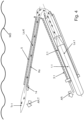
- 3 shows an alternative embodiment in a plan view from above, 4 in a side view a further alternative embodiment.
- the watercraft is traveling in a direction FR (in 3 in the drawing plane and from bottom to top, in 4 perpendicular or oblique to the plane of the drawing).
- the longitudinal axis La.1 of the ramp 1.1 and the longitudinal axis La.K of the channel Ka also lie in the planes of the drawing 3 and 4 .
- Situations shown are produced at least when starting the underwater running body 1.1. It is possible that a ramp actuator (not shown) has previously pivoted the ramp 1.1 into the firing position shown.
- the longitudinal axis La.K of the channel Ka is perpendicular to the direction of travel FR, the longitudinal axis La.1 of the ramp 3.1 at an angle to the direction of travel FR.
- the ejection direction AR of the underwater rocket 1.1 thus points obliquely forward.
- the deflection angle is preferably between 90° and 180° (inclusive).
- the ejection direction AR of the underwater rocket 1.1 obliquely downwards and is perpendicular or oblique to the travel direction FR of the watercraft.
- the longitudinal axis La.K of the channel Ka and thus the outlet direction AR.T of the propellant Tr.1 points obliquely upwards. This prevents propellant Tr.1 in the channel Ka accumulates and bubbles emerge, leaving the craft in a trail of bubbles.
- Reference sign 1.1 first underwater barrel body in the form of an underwater rocket includes the engine Tw.1, is included in the first canister 2.1 1.2 second underwater barrel body in the form of an underwater rocket is added to the second canister 2.2 2.1 first canister in which the first underwater rocket 1.1 is stored 2.2 second canister in which the second underwater missile 1.2 is stored 3.1 first ramp in which the first canister 2.1 is stored with the first underwater rocket 1.1 and which leads the first underwater rocket 1.1 at the start 3.2 second ramp, in which the second canister 2.2 is stored with the second underwater rocket 1.2 and which guides the second underwater rocket 1.2 at the start 4 Wall of the common chamber Km behind the two ramps 3.1 and 3.2 5 Wall of a canal Ka leading outwards from the chamber Km 6.1 Muzzle flap or membrane in front of the first ramp 3.1 is opened or pierced when the underwater rocket 1.1 is launched 6.2 Muzzle flap or membrane in front of the second ramp 3.2 is opened or pierced when the underwater rocket 1.2 is launched 7.1, 7.2 front membrane of the can
Description
Die Erfindung betrifft eine Startvorrichtung zum Starten eines Unterwasser-Laufkörpers von einer Plattform, insbesondere von einem Wasserfahrzeug, aus sowie ein Verfahren unter Verwendung einer solchen Startvorrichtung.The invention relates to a launching device for launching an underwater running body from a platform, in particular from a watercraft, and a method using such a launching device.
Bekannt ist, eine große Rakete von einem U-Boot senkrecht nach oben zu starten. Beispielsweise mittels Druckluft wird die Rakete aus der Rampe des U-Boots ausgestoßen, während das U-Boot sich unter Wasser und nahe der Wasseroberfläche befindet. Nachdem die ausgestoßene Rakete das Wasser verlassen hat, wird ein Triebwerk der Rakete gezündet.It is known to launch a large rocket vertically upwards from a submarine. For example, by means of compressed air, the missile is ejected from the submarine's ramp while the submarine is underwater and near the water's surface. After the ejected rocket leaves the water, one of the rocket's engines is fired.
Vertikale Abschussrampen für Raketen sind von Unterwasserfahrzeugen und auch von Überwasserschiffen her bekannt. In manchen Anwendungen wird die Rakete in einem Kanister in die Rampe verbracht und aus diesem Kanister senkrecht oder schräg nach oben ausgestoßen, wobei der Kanister in der Abschussrampe verbleibt.Vertical launch pads for rockets are known from underwater vehicles and also from surface ships. In some applications, the missile is loaded into the launcher in a canister and ejected from the canister vertically or at an angle, leaving the canister in the launch pad.
Aufgabe der Erfindung ist es, eine Startvorrichtung mit den Merkmalen des Oberbegriffs des Anspruchs 1 und ein Verfahren mit den Merkmalen des Oberbegriffs des Anspruchs 15 bereitzustellen, bei welchen die Startvorrichtung einen Start des Unterwasser-Laufkörpers unter Wasser ermöglicht und welche einfacher aufgebaut ist als bekannte Startvorrichtungen.The object of the invention is to provide a starting device with the features of the preamble of claim 1 and a method with the features of the preamble of claim 15, in which the starting device enables the underwater running body to be started under water and which is simpler in construction than known starting devices .
Gelöst wird diese Aufgabe durch eine Startvorrichtung mit den in Anspruch 1 angegebenen Merkmalen und ein Verfahren mit den in Anspruch 15 angegebenen Merkmalen. Vorteilhafte Weiterbildungen ergeben sich aus den Unteransprüchen, der nachfolgenden Beschreibung sowie den Zeichnungen.This object is achieved by a starting device having the features specified in claim 1 and a method having the features specified in claim 15 . Advantageous developments result from the dependent claims, the following description and the drawings.
Die erfindungsgemäße Startvorrichtung vermag unter Wasser einen Unterwasser-Laufkörper von einem Wasserfahrzeug oder von einer anderen Plattform aus zu starten. Der zu startende Unterwasser-Laufkörper umfasst ein Triebwerk. Dieses Triebwerk lässt sich aktivieren und stößt nach der Aktivierung ein Treibmittel aus.The starting device according to the invention is able to start an underwater running body from a watercraft or from another platform under water. The underwater running body to be launched includes an engine. This engine can be activated and ejects a propellant when activated.
Die lösungsgemäße Startvorrichtung umfasst
- eine Rampe und
- eine Treibmittel-Umlenkeinheit.
- a ramp and
- a propellant deflection unit.
Die Rampe erstreckt sich entlang einer Rampen-Längsachse und vermag den Unterwasser-Laufkörper unter Wasser zu umschließen und zu halten. Die Startvorrichtung vermag das Triebwerk des Unterwasser-Laufkörpers zu aktivieren, während der Unterwasser-Laufkörper unter Wasser von der Rampe umschlossen und gehalten ist. Nachdem der Unterwasser-Laufkörper gestartet wird, lenkt die Rampe den gestarteten Unterwasser-Laufkörper abhängig von der Orientierung der Rampen-Längsachse auf einem ersten Teil von dessen Bewegungsbahn.The ramp extends along a longitudinal axis of the ramp and is able to enclose and hold the underwater running body under water. The launcher is capable of activating the engine of the submersible while the submersible is enclosed and supported underwater by the ramp. After the underwater running body is launched, the ramp steers the launched underwater running body on a first part of its trajectory depending on the orientation of the ramp's longitudinal axis.
Die Treibmittel-Umlenkeinheit lenkt ausgestoßenes Treibmittel in eine Auslassrichtung. Diese Auslassrichtung des Treibmittels zeigt senkrecht oder schräg von der Plattform weg, an welcher die Startvorrichtung montiert ist und von welcher aus der Unterwasser-Laufkörper gestartet wird.The propellant deflection unit directs ejected propellant in an outlet direction. This outlet direction of the propellant points perpendicularly or obliquely from the platform away, on which the starting device is mounted and from which the underwater running body is started.
Ein Unterwasser-Laufkörper im Sinne der Erfindung ist ein unbemanntes Unterwasserfahrzeug, welches einen Treibstoff in Treibmittel umwandelt, z.B. verbrennt, das erzeugte Treibmittel ausstößt und durch den Ausstoß des Treibmittels durch das Wasser bewegt wird. Möglich ist, dass der Unterwasser-Laufkörper ein zusätzliches Antriebsmittel aufweist. Der Unterwasser-Laufkörper kann autonom operieren oder beispielsweise über einen Draht ferngesteuert sein.An underwater running body within the meaning of the invention is an unmanned underwater vehicle which converts fuel into propellant, e.g. burns it, ejects the propellant produced and is moved through the water by the ejection of the propellant. It is possible that the underwater running body has an additional drive means. The underwater running body can operate autonomously or be remotely controlled, for example via a wire.
Lösungsgemäß vermag die Startvorrichtung einen Unterwasser-Laufkörper mit einem Triebwerk zu starten. Ein Unterwasser-Laufkörper mit einem Triebwerk, welches ein Treibmittel ausstößt, kann in vielen Fällen eine höhere Beschleunigung erzielen und rascher ein Ziel unter Wasser erreichen als ein Unterwasser-Laufkörper, der ausschließlich von mindestens einem Propeller angetrieben wird. Dies ist in manchen Anwendungen wichtig, beispielsweise wenn der Unterwasser-Laufkörper ein angreifendes Torpedo neutralisieren soll, bevor dieses die Plattform, beispielsweise ein Überwasserschiff, oder ein anderes Ziel erreicht.According to the solution, the starting device is able to start an underwater running body with an engine. An underwater running body with an engine which ejects a propellant can in many cases achieve greater acceleration and reach a target under water more quickly than an underwater running body which is solely driven by at least one propeller. This is important in some applications, for example when the submersible is intended to neutralize an attacking torpedo before it reaches the platform, such as a surface vessel, or other target.
Der Start des Unterwasser-Laufkörpers mit Hilfe der lösungsgemäßen Startvorrichtung hängt überhaupt nicht oder wenigstens in geringerem Ausmaß als bekannte Startvorrichtungen von der Wassertiefe der Startvorrichtung im Moment des Starts ab.The launch of the underwater running body using the launch device according to the solution does not depend at all or at least to a lesser extent than known launch devices on the water depth of the launch device at the moment of launch.
Die lösungsgemäße Startvorrichtung vermag den Unterwasser-Laufkörper aufzunehmen und zu starten, während die Rampe der Startvorrichtung und der Unterwasser-Laufkörper sich unter der Wasseroberfläche befinden. Auch das Ziel für den Unterwasser-Laufkörper kann sich vollständig oder wenigstens teilweise unter der Wasseroberfläche befinden. Möglich ist, den Unterwasser-Laufkörper für einen Einsatz ausschließlich unter Wasser auszugestalten. Die Bewegung des Unterwasser-Laufkörpers lässt sich in diesem Falle leichter regeln, als wenn der Unterwasser-Laufkörper sowohl durch das Wasser als auch durch die Luft fliegen würde. Insbesondere wird verhindert, dass der Unterwasser-Laufkörper rasch und in schwer oder gar nicht zu regelnder Weise seine Bewegungsbahn ändert, was passieren kann, wenn der Unterwasser-Laufkörper vom Wasser oder von der Luft aus die Wasseroberfläche durchstößt.The starting device according to the solution is able to pick up and start the underwater running body, while the ramp of the starting device and the underwater running body are below the water surface. The target for the underwater barrel can also be located completely or at least partially below the water surface. It is possible to configure the underwater barrel for use exclusively under water. In this case, the movement of the underwater carriage can be controlled more easily than if the underwater carriage were to fly both through the water and through the air. In particular, the underwater carriage is prevented from changing its trajectory quickly and in a manner that is difficult or impossible to control, which can happen when the underwater carriage penetrates the water surface from the water or from the air.
Die lösungsgemäße Startvorrichtung vermag das Triebwerk des Unterwasser-Laufkörpers zu aktivieren, während der Unterwasser-Laufkörper sich noch in der Rampe befindet und die Rampe den Unterwasser-Laufkörper umschließt und hält. Die Rampe führt den gestarteten Unterwasser-Laufkörper auf einem ersten Teil der Bewegungsbahn, bis der Unterwasser-Laufkörper eine gewisse Geschwindigkeit und damit kinetische Energie erreicht hat und die Gefahr reduziert ist, dass Wasserströmungen etc. den Unterwasser-Laufkörper vom Weg abbringen. Diese Wasserströmungen können beispielsweise aufgrund der Fortbewegung einer Plattform, welche die lösungsgemäße Startvorrichtung trägt, durch das Wasser auftreten. Das Triebwerk ist mit einem Treibstoff gefüllt und stößt nach der Aktivierung erzeugtes Treibmittel aus. Durch den Ausstoß des Treibmittels wird der Unterwasser-Laufkörper aus der Rampe geschoben. Dank des Triebwerks wird der Unterwasser-Laufkörper aus der Rampe ausgestoßen, ohne dass Druckluft oder ein Kolben oder ein sonstiger Ausstoß-Mechanismus erforderlich sind, um den Unterwasser-Laufkörper auszustoßen. Ein solcher Mechanismus erfordert Platz und elektrische und / oder hydraulische und / oder mechanische Energie. Beides steht an Bord einer Plattform in der Regel nur begrenzt zur Verfügung, insbesondere wenn die Plattform ein Unterwasserfahrzeug ist. Außerdem erfordert ein Ausstoß-Mechanismus oft eine regelmäßige Wartung und / oder Instandhaltung, und die Gefahr besteht, dass dieser Ausstoß-Mechanismus ausfällt. Ein Pneumatik-Kreislauf für einen pneumatisch betriebenen Ausstoß-Mechanismus hat den weiteren Nachteil, dass Gasblasen aus einem Leck austreten und an die Wasseroberfläche steigen können, was in vielen Fällen unerwünscht ist. Die Erfindung führt somit zu einer Startvorrichtung mit einem einfacheren mechanischen Aufbau und verringert das Risiko, dass schon vor dem Start Gasblasen austreten.The starting device according to the solution is able to activate the engine of the underwater running body while the underwater running body is still in the ramp and the ramp encloses and holds the underwater running body. The ramp guides the launched underwater running body on a first part of the trajectory until the underwater running body has reached a certain speed and thus kinetic energy and the risk is reduced that water currents etc. will throw the underwater running body off the path. These water currents can occur, for example, due to the movement of a platform, which carries the starting device according to the solution, through the water. The thruster is filled with a propellant and upon activation ejects generated propellant. The underwater running body is pushed out of the ramp by the ejection of the propellant. The thruster ejects the submersible from the ramp without the need for compressed air or a piston or other ejection mechanism to eject the submersible. Such a mechanism requires space and electrical and/or hydraulic and/or mechanical energy. Both are usually only available to a limited extent on board a platform, particularly if the platform is an underwater vehicle. In addition, an ejection mechanism often requires regular servicing and/or maintenance and there is a risk that this ejection mechanism will fail. A pneumatic circuit for a pneumatically operated ejection mechanism has the further disadvantage that gas bubbles can escape from a leak and rise to the water surface, which in many cases is undesirable. The invention thus leads to a starting device with a simpler mechanical structure and reduces the risk of gas bubbles escaping even before the start.
Weil weniger Platz benötigt wird und kein zusätzlicher Ausstoß-Mechanismus zu montieren ist, lässt sich die Startvorrichtung leichter an Bord einer bereits vorhandenen Plattform anbringen. Oft lässt sich die Startvorrichtung mitsamt dem oder jedem Unterwasser-Laufkörper in bereits vorhandene und unter Wasser angeordnete Torpedorohre eines Überwasserfahrzeugs oder Unterwasserfahrzeugs unterbringen.Because less space is required and no additional ejector mechanism needs to be fitted, the launcher is easier to mount onboard an existing platform. The starting device, together with the or each underwater running body, can often be accommodated in already existing torpedo tubes of a surface water vehicle or underwater vehicle that are arranged under water.
Häufig wird ein Unterwasser-Laufkörper in einem Kanister angeliefert. Der Kanister mitsamt dem Unterwasser-Laufkörper wird in die Rampe eingeführt. Wenn das Triebwerk aktiviert wird und Treibmittel ausstößt, so verlässt der Unterwasser-Laufkörper den Kanister, welcher in der Rampe bleibt. Möglich, aber dank der Erfindung nicht erforderlich ist es, dass ein Ausstoß-Mechanismus den Kanister öffnet oder durchstößt, um den Unterwasser-Laufkörper auszustoßen.An underwater barrel body is often delivered in a canister. The canister together with the underwater running body is inserted into the ramp. When the engine is activated and ejects propellant, the underwater barrel exits the canister, which remains in the ramp. It is possible, but not necessary thanks to the invention, for an ejection mechanism to open or pierce the canister in order to eject the underwater barrel body.
Wenn das Triebwerk aktiviert ist, stößt der Unterwasser-Laufkörper in der Rampe Treibmittel in eine Ausstoßrichtung aus, die in der Regel parallel zur Rampen-Längsachse ist und der Richtung, in welche der Unterwasser-Laufkörper die Rampe verlässt, entgegengesetzt ist (actio gleich reactio). Dadurch wird der Unterwasser-Laufkörper in eine Startrichtung parallel zur Rampen-Längsachse verschoben und danach aus der Rampe ausgestoßen. Die Startrichtung des Unterwasser-Laufkörpers zeigt in der Regel von der Plattform weg, und daher zeigt die Ausstoßrichtung des Treibmittels auf die Plattform zu. Insbesondere im Falle eines Wasserfahrzeugs als der Plattform ist unerwünscht, dass das ausgestoßene Treibmittel in das Innere des Wasserfahrzeugs gelangt oder die Rampe oder eine Hülle des Wasserfahrzeugs zu stark erhitzt. Die Treibmittel-Umlenkeinheit verhindert dieses unerwünschte Ereignis.When the thruster is activated, the underwater carriage in the ramp ejects propellant in an ejection direction that is usually parallel to the ramp's longitudinal axis and opposite to the direction in which the underwater carriage exits the ramp (actio equals reactio ). As a result, the underwater running body is displaced in a starting direction parallel to the longitudinal axis of the ramp and is then ejected from the ramp. The launching direction of the submersible body is typically away from the platform, and therefore the ejection direction of the propellant is towards the platform. Particularly in the case of a watercraft as the platform, it is undesirable for the ejected propellant to reach the interior of the watercraft or to heat the ramp or a hull of the watercraft too much. The propellant deflection unit prevents this undesired event.
Eine Gefahr für ein Besatzungsmitglied der Plattform, welche die Startvorrichtung mit der Rampe umfasst, und für die Plattform selber darf auch dann nicht auftreten, wenn der Unterwasser-Laufkörper aufgrund eines Fehlers nicht die Rampe verlässt, nachdem das Triebwerk aktiviert ist, sondern z. B. in der Rampe verklemmt ist oder anderweitig festgehalten wird oder wenn eine Klappe der Rampe nicht geöffnet ist. In diesem Fall stößt der Unterwasser-Laufkörper in der Rampe so lange Treibmittel aus, bis der Treibstoff des Triebwerks vollständig verbraucht ist. Daher wird in der Rampe eine erheblich größere Menge von Treibmittel ausgestoßen als bei einem fehlerfreien Start. Dank der Treibmittel-Umlenkeinheit wird das ausgestoßene Treibmittel trotz dieses Fehlers von der Plattform wegbewegt, nämlich in die Auslassrichtung, welche die Treibmittel-Umlenkeinheit festlegt. Dieses Merkmal verhindert das gefährliche und daher unerwünschte Ereignis, dass das ausgestoßene Treibmittel die Rampe soweit erhitzt, dass Treibmittel oder ein Gefechtskopf des Unterwasser-Laufkörpers explodiert oder sich entzündet oder die erhitzte Rampe oder eine Fahrzeughülle beschädigt werden.A hazard for a crew member of the platform, which includes the launch device with the ramp, and for the platform itself must not occur even if the underwater running body does not leave the ramp after the engine is activated due to a fault, but e.g. B. is stuck in the ramp or is otherwise held or if a flap of the ramp is not open. In this case, the underwater running body ejects propellant in the ramp until the The engine has run out of fuel. Therefore, a significantly larger amount of propellant is expelled in the ramp than in a clean launch. Thanks to the propellant diverter, despite this error, the ejected propellant is moved away from the platform, namely in the outlet direction that the propellant diverter determines. This feature prevents the dangerous and therefore undesirable event of the ejected propellant heating the ramp to the point of exploding or igniting propellant or a warhead of the underwater vehicle, or damaging the heated ramp or a vehicle hull.
Möglich, aber dank der Treibmittel-Umlenkeinheit nicht erforderlich ist es, dass die Startvorrichtung einen Mechanismus aufweist, der das Triebwerk abschaltet oder einen Gefechtskopf deaktiviert, wenn der Unterwasser-Laufkörper nach Aktivieren des Triebwerks aufgrund eines Fehlers nicht die Rampe verlässt.It is possible, but not necessary thanks to the propellant deflection unit, for the launch device to have a mechanism that shuts down the engine or deactivates a warhead if the underwater running body does not leave the ramp after the engine has been activated due to a fault.
In einer Ausführungsform der Erfindung ist die Treibmittel-Umlenkeinheit so ausgestaltet und angeordnet, dass folgendes bewirkt wird:
- Die Auslassrichtung des Treibmittels ist parallel zur Rampen-Längsachse und damit parallel zur Ausstoßrichtung des Unterwasser-Laufkörpers.
- Das von der Treibmittel-Umlenkeinheit umgelenkte Treibmittel tritt aus der Treibmittel-Umlenkeinheit mit einem Abstand, beispielsweise mit einem seitlichen oder vertikalen Versatz, zur Rampen-Längsachse aus.
- The outlet direction of the propellant is parallel to the longitudinal axis of the ramp and thus parallel to the ejection direction of the underwater running element.
- The propellant deflected by the propellant deflection unit exits the propellant deflection unit at a distance, for example with a lateral or vertical offset, from the longitudinal axis of the ramp.
Das Treibmittel wird in dieser Ausgestaltung in die gleiche Richtung wie der Unterwasser-Laufkörper ausgestoßen, aber mit einem seitlichen Versatz und nicht aus der Rampe, sondern aus der Treibmittel-Umlenkeinheit. Bei einem Starten des Unterwasser-Laufkörpers unter Wasser wird in nur eine Richtung ein Impuls auf das umgebende Wasser ausgeübt, nämlich einerseits durch den Unterwasser-Laufkörper und andererseits durch das ausgestoßene Treibmittel. Somit treten nicht an zwei weit voneinander entfernten Stellen im Wasser Verwirbelungen und / oder Gasblasen auf, welche entdeckt werden können und eine Information über die ausstoßende Plattform liefern können.In this embodiment, the propellant is ejected in the same direction as the underwater barrel body, but with a lateral offset and not from the ramp but from the propellant deflection unit. When the underwater running body is started under water, an impulse is exerted on the surrounding water in only one direction, namely on the one hand by the underwater running body and on the other hand by the ejected propellant. This means that turbulence and/or gas bubbles do not occur in two places far apart from each other in the water, which can be discovered and provide information about the issuing platform.
Außerdem ermöglicht diese Ausgestaltung eine besonders kompakte und platzsparende Bauweise. Die gesamte Startvorrichtung erstreckt sich im Wesentlichen entlang der Rampen-Längsachse und hat eine nur relativ geringe Abmessung senkrecht zur Rampen-Längsachse. Dies ist insbesondere dann wichtig, wenn die Startvorrichtung an Bord eines Unterwasserfahrzeugs montiert ist.In addition, this configuration enables a particularly compact and space-saving design. The entire starting device extends essentially along the longitudinal axis of the ramp and has only relatively small dimensions perpendicular to the longitudinal axis of the ramp. This is particularly important when the launcher is mounted onboard a submersible.
In einer alternativen Ausgestaltung schließt die Auslassrichtung des Treibmittels einen spitzen Winkel mit der Rampen-Längsachse ein. Zwischen der Auslassrichtung und der Ausstoßrichtung des Unterwasser-Laufkörpers tritt bevorzugt ein spitzer oder stumpfer Winkel auf. Die Treibmittel-Umlenkeinheit lenkt das Treibmittel um einen stumpfen Winkel um. Bevorzugt ist der Umlenkwinkel größer als 60°, besonders bevorzugt größer als 120°.In an alternative embodiment, the outlet direction of the propellant encloses an acute angle with the longitudinal axis of the ramp. An acute or obtuse angle preferably occurs between the outlet direction and the ejection direction of the underwater running body. The propellant deflection unit deflects the propellant through an obtuse angle. The deflection angle is preferably greater than 60°, particularly preferably greater than 120°.
Bei der Ausgestaltung mit dem stumpfen Umlenk-Winkel wächst der Abstand zwischen dem gestarteten Unterwasser-Laufkörper und dem Treibmittel, welches die Treibmittel-Umlenkeinheit verlassen hat, während der Bewegung des Unterwasser-Laufkörpers. Hierdurch wird mit größerer Sicherheit eine Wechselwirkung zwischen dem Treibmittel, welches die Treibmittel-Umlenkeinheit verlassen hat, und dem Unterwasser-Laufkörper vermieden. Diese Wechselwirkung ist in manchen Situationen unerwünscht, beispielsweise weil die Bewegungs-Regelung des Unterwasser-Laufkörpers erschwert werden kann oder eine aktive oder passive Sonaranlage des Unterwasser-Laufkörpers verfälschte Ergebnisse liefern kann.In the obtuse turning angle design, the distance between the launched underwater vehicle and the propellant which has left the propellant turning unit increases during movement of the underwater vehicle. As a result, an interaction between the propellant which has left the propellant deflection unit and the underwater running body is avoided with greater certainty. This interaction is undesirable in some situations, for example because the movement control of the underwater running body can be made more difficult or an active or passive sonar system of the underwater running body can deliver incorrect results.
In einer Ausgestaltung umfasst die Startvorrichtung zusätzlich zu der ersten Rampe eine zweite Rampe, die sich entlang einer zweiten Rampen-Längsachse erstreckt und einen Abstand zur ersten Rampen-Längsachse aufweist. Die beiden Rampen-Längsachsen können parallel zueinander angeordnet sein oder einen Winkel einschließen. Die zweite Rampe vermag einen zweiten Unterwasser-Laufkörper unter Wasser zu umschließen, zu halten und zu lenken.In one embodiment, the starting device includes, in addition to the first ramp, a second ramp which extends along a second longitudinal axis of the ramp and is at a distance from the first longitudinal axis of the ramp. The two longitudinal axes of the ramp can be arranged parallel to one another or at an angle lock in. The second ramp is capable of enclosing, supporting and directing a second underwater carriage underwater.
Dank der zweiten Rampe vermag die Startvorrichtung gleichzeitig oder nacheinander zwei Unterwasser-Laufkörper zu starten, ohne dass zwischendurch ein Nachladen in eine Rampe erforderlich ist.Thanks to the second ramp, the launcher is able to launch two underwater running bodies simultaneously or one after the other without having to be reloaded onto a ramp in between.
Möglich ist, dass die Startvorrichtung eine weitere Treibmittel-Umlenkeinheit umfasst. Jeder Rampe ist eine eigene Treibmittel-Umlenkeinheit zugeordnet. In einer bevorzugten Ausgestaltung ist hingegen dieselbe Treibmittel-Umlenkeinheit sowohl der ersten Rampe als auch der zweiten Rampe zugeordnet. Die Startvorrichtung ist so ausgestaltet und angeordnet, dass folgendes bewirkt wird:
- Ein Treibmittel, das vom ersten Unterwasser-Laufkörper in der ersten Rampe ausgestoßen wird, wird in die zugeordnete Treibmittel-Umlenkeinheit geleitet.
- Ein Treibmittel, das vom zweiten Unterwasser-Laufkörper in der zweiten Rampe ausgestoßen wird, wird in dieselbe zugeordnete Treibmittel-Umlenkeinheit geleitet.
- A propellant ejected from the first underwater barrel in the first ramp is directed into the associated propellant diverter unit.
- Propellant ejected from the second undersea barrel in the second ramp is directed into the same associated propellant diverter.
In dieser Ausgestaltung wird also dieselbe Treibmittel-Umlenkeinheit für mindestens zwei verschiedene Rampen verwendet. Diese Ausgestaltung spart Platz ein im Vergleich zu einer Ausgestaltung, bei der jeder Rampe eine eigene Treibmittel-Umlenkeinheit zugeordnet ist.In this embodiment, the same propellant deflection unit is used for at least two different ramps. This embodiment saves space compared to an embodiment in which each ramp is assigned its own propellant deflection unit.
Möglich ist, dass einer ersten Gruppe mit mindestens zwei Rampen eine erste Treibmittel-Umlenkeinheit zugeordnet ist und einer zweiten Gruppe mit mindestens einer weiteren Rampe eine zweite Treibmittel-Umlenkeinheit.It is possible for a first group with at least two ramps to be assigned a first propellant deflection unit and for a second group with at least one further ramp to be assigned a second propellant deflection unit.
Vorzugsweise umfasst die Startvorrichtung eine Arretier-Vorrichtung, welche der ersten Rampe zugeordnet ist. Möglich ist, dass der zweiten Rampe eine gleichartige weitere Arretier-Vorrichtung zugeordnet ist. Die oder jede Arretier-Vorrichtung lässt sich in einen Arretier-Zustand und in einen Freigabe-Zustand überführen, und zwar bevorzugt unabhängig von jeder anderen Arretier-Vorrichtung.The starting device preferably includes a locking device which is assigned to the first ramp. It is possible that a further locking device of the same type is assigned to the second ramp. The or each locking device can be switched into a locking state and into a release state, preferably independently of any other locking device.
Die zugeordnete Arretier-Vorrichtung in dem Arretier-Zustand verhindert, dass der arretierte Unterwasser-Laufkörper in der Rampe sich relativ zur Rampe bewegt, insbesondere verkantet oder aus der Rampe rutscht. Die Arretier-Vorrichtung im Freigabe-Zustand ermöglicht, dass der Unterwasser-Laufkörper aus der Rampe austritt.The associated locking device in the locked state prevents the locked underwater running body in the ramp from moving relative to the ramp, in particular from tilting or slipping out of the ramp. The detent in the released state allows the underwater carriage to exit the ramp.
Solange die Arretier-Vorrichtung im Arretier-Zustand ist, unterbindet oder blockiert in einer bevorzugten Ausgestaltung die Startvorrichtung nicht nur eine Bewegung des Unterwasser-Laufkörpers, sondern auch ein Aktivieren des Triebwerks. Dadurch lässt sich das Triebwerk erst dann aktivieren, wenn die Arretier-Vorrichtung in den Freigabe-Zustand überführt ist.In a preferred embodiment, as long as the locking device is in the locking state, the starting device not only prevents or blocks movement of the underwater running body, but also activation of the engine. As a result, the engine can only be activated when the locking device has been transferred to the release state.
Die Arretier-Vorrichtung verhindert im Arretier-Zustand, dass der Unterwasser-Laufkörper eine unerwünschte Bewegung relativ zur Rampe ausgeführt, bevor das Triebwerk aktiviert ist. Eine solche unerwünschte Bewegung könnte den Unterwasser-Laufkörper und / oder die Rampe beschädigen oder dazu führen, dass der Unterwasser-Laufkörper die Rampe nicht verlassen kann. Das Triebwerk lässt sich gemäß der bevorzugten Ausgestaltung erst dann aktivieren, und der Unterwasser-Laufkörper kann die Rampe erst dann verlassen, wenn die Arretier-Vorrichtung im Freigabe-Zustand ist. Dank dieser Ausgestaltung wird das unerwünschte Ereignis verhindert, dass das Triebwerk des Unterwasser-Laufkörpers aktiviert wird, obwohl die Arretier-Vorrichtung noch im Arretier-Zustand ist. Dieses unerwünschte Ereignis kann dazu führen, dass der Unterwasser-Laufkörper mit aktiviertem Triebwerk in der Rampe festgehalten wird, beispielsweise weil ausgestoßenes Treibmittel es verhindert, dass die Arretier-Vorrichtung in den Freigabe-Zustand überführt wird.In the locked state, the locking device prevents the underwater running body from performing an undesired movement relative to the ramp before the engine is activated. Such undesired movement could damage the underwater carriage and/or the ramp or result in the underwater carriage not being able to leave the ramp. According to the preferred embodiment, the engine can only be activated and the underwater running body can only leave the ramp when the locking device is in the released state. Thanks to this configuration, the undesired event that the drive mechanism of the underwater running body is activated, although the locking device is still in the locking state, is prevented. This undesired event can result in the underwater drive body being stuck in the ramp with the engine activated, for example because ejected propellant prevents the locking device from being placed in the release state.
In einer Fortbildung dieser Ausgestaltung umfasst die Startvorrichtung einen Positions-Sensor. Dieser Positions-Sensor vermag positiv das Ereignis zu entdecken, dass die Arretier-Vorrichtung sich im Freigabe-Zustand befindet. "Positiv entdecken" bedeutet, dass der Positions-Sensor ein Signal erzeugt, wenn er das Ereignis entdeckt hat. Die Startvorrichtung vermag das Triebwerk zu aktivieren, nachdem der Positions-Sensor entdeckt hat, dass die Arretier-Vorrichtung sich im Freigabe-Zustand befindet. Somit wird das Triebwerk als Reaktion auf das Ereignis aktiviert, dass die Arretier-Vorrichtung im Freigabe-Zustand ist. Das Aktivieren des ersten Triebwerks kann ferner unterbunden sein, solange der Positions-Sensor nicht dieses Ereignis entdeckt hat.In a further development of this refinement, the starting device includes a position sensor. This position sensor can positively detect the event that the locking device is in the release state. "Detect positive" means that the position sensor generates a signal when it detects the event. The starting device is able to activate the engine after the position sensor has detected that the locking device is in the unlocked state. Thus, the engine is activated in response to the event that the locking device is in the release state. Activation of the first thruster may also be inhibited until the position sensor detects this event.
Durch diese Ausgestaltung mit dem Positions-Sensor lässt sich eine gesetzliche Anforderung erfüllen, nämlich dass ein Triebwerk erst dann aktiviert werden darf, wenn ein spezifisches sicherheitsrelevantes Ereignis physikalisch entdeckt worden ist. Gemäß dieser Ausgestaltung wird als sicherheitsrelevantes Ereignis das Ereignis verwendet, dass der Positions-Sensor entdeckt, dass die Arretier-Vorrichtung sich im Freigabe-Zustand befindet, und ein entsprechendes Signal erzeugt hat. Diese Ausgestaltung zeigt also einen Weg auf, um eine gesetzliche Anforderung an das Aktivieren eines Triebwerks zu erfüllen.This refinement with the position sensor makes it possible to meet a legal requirement, namely that an engine may only be activated when a specific safety-related event has been physically discovered. According to this embodiment, the event that the position sensor discovers that the locking device is in the release state and has generated a corresponding signal is used as the safety-relevant event. This refinement thus shows a way of meeting a legal requirement for activating an engine.
Vorzugsweise sendet der Positions-Sensor dann ein entsprechendes Signal, wenn er den Freigabe-Zustand entdeckt hat. Das Triebwerk lässt sich nur dann aktivieren, wenn das Freigabe-Signal anliegt. Dadurch wird dann, wenn der Positions-Sensor oder ein Steuergerät der Startvorrichtung ausgefallen oder die Signalübermittlung unterbrochen ist, ein sicherer Zustand gewährleistet, nämlich dass das Triebwerk nicht aktiviert wird.The position sensor then preferably sends a corresponding signal when it has discovered the release state. The engine can only be activated if the release signal is present. In this way, if the position sensor or a control unit of the starting device fails or the signal transmission is interrupted, a safe state is ensured, namely that the engine is not activated.
Erfindungsgemäß kann Wasser in die erste Rampe und / oder in die zweite Rampe eindringen, und dies ist erwünscht. Bevorzugt verschließt eine Rampen-Klappe dann die Rampe gegen umgebendes Wasser, wenn die Rampen-Klappe in einem geschlossenen Zustand ist. In einem geöffneten Zustand ermöglicht die Rampen-Klappe, dass Wasser in die Rampe eindringt. Die Startvorrichtung vermag die Rampen-Klappe zu öffnen und dadurch zu ermöglichen, dass Wasser in die Rampe einfließt. Die Startvorrichtung öffnet die Rampen-Klappe, bevor die Startvorrichtung das Triebwerk des Unterwasser-Laufkörpers aktiviert. Somit ist der Unterwasser-Laufkörper in der Rampe von Wasser umgeben, wenn sein Triebwerk gezündet wird. Dies erleichtert es, die Bewegungsbahn des Unterwasser-Laufkörpers zu regeln, verglichen mit einer Ausgestaltung, bei der der gestartete Unterwasser-Laufkörper schlagartig auf Wasser trifft.According to the invention, water can penetrate into the first ramp and/or into the second ramp, and this is desirable. A ramp flap preferably then closes the ramp from surrounding water when the ramp flap is in a closed state. In an open condition, the ramp hatch allows water to enter the ramp. The launcher is able to open the ramp flap and thereby allow water to flow into the ramp. The launcher opens the ramp door before the launcher activates the underwater vehicle's engine. Thus, the submersible body is surrounded by water in the ramp when its engine is fired. This makes it easier to control the trajectory of the underwater carriage compared to one Configuration in which the launched underwater running body suddenly hits water.
Erfahrungsgemäß startet die Startvorrichtung den Unterwasser-Laufkörper unter Wasser. Je nach Ausgestaltung der Startvorrichtung und der aktuellen Betriebssituation kann die Auslass-Öffnung der Treibmittel-Umlenkeinheit sich oberhalb oder unterhalb der Wasseroberfläche befinden. Das ausgestoßene und umgelenkte Treibmittel kann also oberhalb oder unterhalb der Wasseroberfläche ausgestoßen werden.Experience has shown that the starting device starts the underwater barrel under water. Depending on the design of the starting device and the current operating situation, the outlet opening of the propellant deflection unit can be located above or below the water surface. The ejected and deflected propellant can thus be ejected above or below the water surface.
In einer Ausgestaltung trennt eine Umlenkeinheit-Klappe die Treibmittel-Umlenkeinheit von dem umgebenden Fluid, im Falle eines Ausstoßes von Treibmittel unterhalb der Wasseroberfläche von dem umgebenden Wasser, solange die Umlenkeinheit-Klappe geschlossen ist. In einer Ausgestaltung vermag ein Stellglied diese Umlenkeinheit-Klappe zu öffnen. In einer bevorzugten Ausgestaltung vermag hingegen ausgestoßenes und umgelenktes Treibmittel die Umlenkeinheit-Klappe zu öffnen oder auch zum Bersten zu bringen. Diese bevorzugte Ausgestaltung spart ein Stellglied für die Umlenkeinheit-Klappe ein.In one embodiment, a deflection unit flap separates the propellant deflection unit from the surrounding fluid, in the case of an ejection of propellant below the water surface from the surrounding water, as long as the deflection unit flap is closed. In one embodiment, an actuator is able to open this deflection unit flap. In a preferred embodiment, on the other hand, ejected and deflected propellant is able to open the deflection unit flap or cause it to burst. This preferred embodiment saves an actuator for the deflection unit flap.
In einer Ausgestaltung vermag das umgelenkte Treibmittel nur dann die Umlenkeinheit-Klappe zu öffnen, wenn der Druck, den das Treibmittel auf die Klappe ausübt, eine vorgegebene Schranke übersteigt. Diese Schranke kann so bemessen sein, dass die Klappe bei einem fehlerfreien Start des Unterwasser-Laufkörpers geschlossen bleibt und der Druck des Treibmittels zusätzlich zum Rückstoß dazu beiträgt, den Unterwasser-Laufkörper auszustoßen. Nur dann, wenn der Unterwasser-Laufkörper aufgrund eines Fehlers nicht die Rampe verlässt, öffnet der Druck des ausgestoßenen Treibmittels die Klappe.In one embodiment, the deflected propellant is only able to open the deflection unit flap when the pressure exerted by the propellant on the flap exceeds a predetermined limit. This barrier can be dimensioned in such a way that the flap remains closed in the event of a faultless launch of the underwater vehicle and the pressure of the propellant contributes in addition to the recoil to ejecting the underwater vehicle. Only if the submersible body does not leave the ramp due to a fault does the pressure of the ejected propellant open the flap.
Die Umlenkeinheit-Klappe im geschlossenen Zustand verhindert, dass umgebendes Fluid, insbesondere Wasser, in die Treibmittel-Umlenkeinheit eindringen kann. Weiterhin wird dann, wenn die Plattform ein Wasserfahrzeug ist, ermöglicht, dass die Umlenkeinheit-Klappe im geschlossenen Zustand zu einer strömungsgünstigen Form des Wasserfahrzeugs beiträgt. Dies reduziert die Gefahr, dass an einer Auslassöffnung der Treibmittel-Umlenkeinheit Verwirbelungen von Wasser auftreten können.In the closed state, the deflection unit flap prevents the surrounding fluid, in particular water, from penetrating into the propellant deflection unit. Furthermore, when the platform is a watercraft, it allows the diverter unit flap to have a streamlined shape when closed of the watercraft contributes. This reduces the risk of water turbulence occurring at an outlet opening of the propellant deflection unit.
Wenn das ausgestoßene Treibmittel die Umlenkeinheit-Klappe zu öffnen vermag, ist es nicht erforderlich, die Umlenkeinheit-Klappe mit Hilfe eines Stellglieds zu öffnen. Ein solches Stellglied kann defekt sein. Außerdem kann es in manchen Anwendungen zu viel Zeit kosten, die Umlenkeinheit-Klappe mit Hilfe eines Stellglieds zu öffnen. Das Öffnen mit Hilfe des Treibmittels funktioniert rasch und ohne ein Stellglied.If the ejected propellant is capable of opening the diverter door, it is not necessary to open the diverter door by means of an actuator. Such an actuator may be defective. In addition, in some applications it may take too much time to open the diverter unit flap using an actuator. Opening with the help of the propellant works quickly and without an actuator.
In einer Anwendung ist die lösungsgemäße Startvorrichtung an Bord eines Wasserfahrzeugs montiert. Bevorzugt ist die Treibmittel-Umlenkeinheit so an Bord dieses Wasserfahrzeugs montiert, dass in einer Standard-Schwimmlage des Wasserfahrzeugs folgendes bewirkt wird: Die gesamte Bewegungsbahn oder wenigstens die letzte Strecke der Bewegungsbahn von Treibmittel, welches in die Treibmittel-Umlenkeinheit hineingeleitet wird und durch die Treibmittel-Umlenkeinheit bewegt wird, ist waagerecht oder ansteigend.In one application, the starting device according to the solution is mounted on board a watercraft. The propellant deflection unit is preferably mounted on board this watercraft in such a way that the following is effected in a standard floating position of the watercraft: the entire trajectory or at least the last stretch of the trajectory of propellant, which is directed into the propellant deflection unit and through the propellant - Deflection unit is moved is horizontal or ascending.
Diese Ausgestaltung verhindert das unerwünschte Ereignis, dass Gase in der Treibmittel-Umlenkeinheit verbleiben und erst allmählich während der Fahrt des Wasserfahrzeugs austreten. Das Wasserfahrzeug würde dann eine Blasenspur hinter sich hier ziehen, was insbesondere für ein Unterwasserfahrzeug oft unerwünscht ist. Dank der Ausgestaltung treten alle Gase vielmehr in einem einzigen Schwall aus.This refinement prevents the undesirable occurrence of gases remaining in the propellant deflection unit and only gradually escaping while the watercraft is in motion. The watercraft would then leave a trail of bubbles behind it, which is often undesirable, especially for an underwater vehicle. Rather, thanks to the design, all of the gases exit in a single gush.
In einer Ausgestaltung umfasst die Startvorrichtung ein Rampen-Stellglied. Dieses Rampen-Stellglied vermag die Rampe zu verschwenken. Insbesondere lässt sich dadurch die Ausstoßrichtung verändern, in welche der Unterwasser-Laufkörper aus der Rampe ausgestoßen wird. In einer Ausgestaltung bewirkt ein Verschwenken der Rampe, dass auch die Auslassrichtung verändert wird, in welche Treibmittel aus der Treibmittel-Umlenkeinheit ausgelassen wird.In one embodiment, the starting device includes a ramp actuator. This ramp actuator is able to pivot the ramp. In particular, this makes it possible to change the ejection direction in which the underwater running body is ejected from the ramp. In one embodiment, a pivoting of the ramp has the effect that the outlet direction in which propellant is discharged from the propellant deflection unit is also changed.
Das Rampen-Stellglied vermag die Rampe zu verschwenken und damit die Orientierung der Rampen-Längsachse relativ zu der Plattform zu verändern. Damit lässt sich der Unterwasser-Laufkörper in eine gewünschte von mehreren möglichen Richtungen starten. Im Falle eines Wasserfahrzeugs als der Plattform wird ermöglicht, dass die unter Wasser angeordnete Rampe sich in einer hydrodynamisch günstigen Position relativ zu der Fahrtrichtung des Wasserfahrzeugs befindet, bevor der Unterwasser-Laufkörper in der Rampe gestartet wird. Die Rampe ruft daher während der Fahrt des Wasserfahrzeugs einen relativ geringen Wasserwiderstand hervor. Wenn der Unterwasser-Laufkörper gestartet werden soll, verschwenkt das Rampen-Stellglied die Rampe relativ zur Fahrzeughülle in eine für den Start gewünschte Position. Beispielsweise verschwenkt das Rampen-Stellglied die erste Rampe) aus einer Fahrt-Position in eine Abschuss-Position, bevor das Triebwerk aktiviert wird.The ramp actuator is capable of pivoting the ramp and thereby changing the orientation of the ramp's longitudinal axis relative to the platform. This allows the underwater running body to be launched in a desired one of several possible directions. In the case of a watercraft as the platform, the underwater ramp is allowed to be in a hydrodynamically favorable position relative to the direction of travel of the watercraft before the underwater vehicle is launched in the ramp. The ramp therefore causes relatively little water resistance while the watercraft is moving. When the underwater vehicle is to be launched, the ramp actuator pivots the ramp relative to the vehicle hull to a desired position for launch. For example, the ramp actuator pivots the first ramp(s) from a cruise position to a launch position before the engine is activated.
Die lösungsgemäße Startvorrichtung ist ein Bestandteil einer Plattform, insbesondere eines Wasserfahrzeugs, oder lässt sich wenigstens zeitweise an Bord einer Plattform montieren. Insbesondere dank der Treibmittel-Umlenkeinheit ist es oft mit geringem Aufwand möglich, eine lösungsgemäße Startvorrichtung nachträglich an Bord einer Plattform zu montieren oder eine vorhandene Startvorrichtung zu ergänzen und dadurch die Betriebssicherheit zu steigern.The starting device according to the solution is a component of a platform, in particular a watercraft, or can be mounted on board a platform at least temporarily. Thanks in particular to the propellant deflection unit, it is often possible with little effort to retrofit a starting device according to the solution on board a platform or to supplement an existing starting device and thereby increase operational reliability.
In einer Ausgestaltung umfasst dieses Wasserfahrzeug ein Waffenrohr, z.B. ein Torpedorohr oder ein Rohr, um Minen oder Behälter oder Unterwasser-Schwimmhilfen auszustoßen. Die gesamte Startvorrichtung oder wenigstens die Rampe mit dem Unterwasser-Laufkörper und der optionalen Arretier-Vorrichtung ist in diesem Waffenrohr angeordnet. Möglich ist, dass ein Adapter in das Innere des Waffenrohrs eingesetzt ist, um den Abstand zwischen dem größeren Innendurchmesser des Waffenrohrs und dem kleineren Außendurchmesser der Rampe zu überbrücken. Möglich ist sogar, dass zwei Rampen einer lösungsgemäßen Startvorrichtung mit Hilfe eines Adapters in das Innere desselben Waffenrohrs eingesetzt sind. Möglich ist auch, die Startvorrichtung an einer Außenhülle des Wasserfahrzeugs zu montieren, so dass die Startvorrichtung dauerhaft von Wasser umgeben ist und rasch zum Starten eines Unterwasserlaufkörpers bereitgemacht werden kann.In one embodiment, this watercraft includes a weapon tube, for example a torpedo tube or a tube to eject mines or containers or underwater swimming aids. The entire starting device or at least the ramp with the underwater barrel body and the optional locking device is arranged in this weapon barrel. It is possible that an adapter is inserted into the inside of the gun barrel in order to bridge the distance between the larger inside diameter of the gun barrel and the smaller outside diameter of the ramp. It is even possible that two ramps of a starting device according to the solution are inserted into the interior of the same weapon barrel with the aid of an adapter. It is also possible to mount the starting device on an outer hull of the watercraft so that the launching device is permanently surrounded by water and can be quickly prepared for launching an underwater running body.
Die Plattform mit der Startvorrichtung kann ein bemanntes oder unbemanntes Überwasserfahrzeug oder Unterwasserfahrzeug sein. Dieses Wasserfahrzeug kann einen eigenen Antrieb aufweisen oder ohne einen eigenen Antrieb ausgestaltet sein. Die Plattform kann auch stationär auf dem Wasser angeordnet sein, beispielsweise an Bord einer Bohrinsel oder eines Schwimmkörpers, oder an Land und dort an einer Küste montiert sein, beispielsweise um einen Hafen vor Angriffen zu schützen.The launcher platform may be a manned or unmanned surface vehicle or underwater vehicle. This watercraft can have its own drive or be designed without its own drive. The platform can also be stationary on the water, for example on board an oil rig or a buoy, or mounted on land and there on a shore, for example to protect a harbor from attack.
Nachfolgend ist die erfindungsgemäße Startvorrichtung anhand eines in den Zeichnungen dargestellten Ausführungsbeispiels näher erläutert. Hierbei zeigen:
-
Fig. 1 in einer Seitenansicht eine lösungsgemäße Startvorrichtung mit zwei Rampen für zwei Unterwasser-Raketen, wobei das Raketen-Triebwerk einer Unterwasser-Rakete gerade gezündet worden ist und die andere Unterwasser Rakete noch arretiert ist; -
Fig. 2 eine beispielhafte Arretier-Vorrichtung für eine Unterwasser-Rakete in drei aufeinanderfolgenden Zuständen; -
Fig. 3 in einer Draufsicht eine Abwandlung der Startvorrichtung vonFig. 1 ; -
Fig. 4 in einer Seitenansicht eine weitere Abwandlung der Startvorrichtung vonFig. 1 .
-
1 in a side view a solution-based launch device with two ramps for two underwater rockets, the rocket engine of an underwater rocket has just been ignited and the other underwater rocket is still locked; -
2 an exemplary locking device for an underwater missile in three consecutive states; -
3 in a plan view a modification of the starting device from1 ; -
4 in a side view a further modification of the starting device from1 .
Im Ausführungsbeispiel wird die Erfindung in einer Startvorrichtung angewendet, welche an Bord eines Unterwasserfahrzeugs, beispielsweise an Bord eines bemannten Unterseeboots, angeordnet ist. Das Unterwasserfahrzeug besitzt eine Fahrzeughülle Fh, beispielsweise einen Druckkörper oder eine Außenhülle. Die lösungsgemäße Startvorrichtung ist bündig in diese Fahrzeughülle Fh eingelassen. Bevorzugt ist die lösungsgemäße Startvorrichtung vollständig außerhalb des Druckkörpers angeordnet, also zwischen Druckkörper und Außenhülle, und ist bei einer Tauchfahrt dem Druck des umgebenden Wassers ausgesetzt.In the exemplary embodiment, the invention is used in a starting device which is arranged on board an underwater vehicle, for example on board a manned submarine. The underwater vehicle has a vehicle hull Fh, for example a pressure hull or an outer hull. The starting device according to the solution is embedded flush in this vehicle shell Fh. The starting device according to the solution is preferably arranged completely outside the pressure hull, ie between the pressure hull and the outer shell, and is exposed to the pressure of the surrounding water during a diving trip.
Die Erfindung lässt sich genauso gut an Bord eines Überwasserfahrzeugs anwenden. Die Startvorrichtung ist in dieser Anwendung an einem Bereich der Fahrzeughülle Fh des Überwasserfahrzeugs montiert, welcher beim Einsatz dauerhaft unterhalb der Wasseroberfläche verbleibt. Die Unterwasser-Rakete verbleibt während der gesamten Fahrt unter Wasser.The invention can be used on board a surface vehicle as well. In this application, the starting device is mounted on an area of the vehicle hull Fh of the surface water vehicle, which area remains permanently below the water surface during use. The underwater missile remains under water throughout the journey.
Die Startvorrichtung vermag mindestens eine Unterwasser-Rakete, im Ausführungsbeispiel mehrere Unterwasser-Raketen, unterhalb der Wasseroberfläche WO zu starten. Unter einer Unterwasser-Rakete wird ein Laufkörper verstanden, der für den Einsatz unter Wasser ausgestaltet ist und ein Raketen-Triebwerk aufweist, also einen Antrieb, der aktiviert werden kann und nach der Aktivierung einen Treibstoff in ein Treibmittel umwandelt, z.B. verbrennt, das erzeugte Treibmittel ausstößt und den Laufkörper dadurch in die zur Ausstoßrichtung des Treibmittels entgegengesetzte Richtung bewegt. Die Unterwasser-Rakete verbleibt im Ausführungsbeispiel während des gesamten Einsatzes unter der Wasseroberfläche WO und kann dem Wasserdruck bis zu einer vorgegebenen maximalen Wassertiefe standhalten. Die Unterwasser-Rakete kann ein Marsch-Triebwerk und zusätzlich ein Start-Triebwerk aufweisen, welches nur zum Start der Unterwasser-Rakete verwendet wird, oder ein einziges Triebwerk für die gesamte Fahrt. Im Folgenden wird die Bezeichnung "Raketen-Triebwerk" für dasjenige Triebwerk verwendet, welches den Start der Unterwasser-Rakete aus der Rampe bewirkt. In der Regel beschleunigt eine Unterwasser-Rakete schneller im Wasser als ein Torpedo, das von mindestens einem Propeller angetrieben wird.The launch device is capable of launching at least one underwater rocket, in the exemplary embodiment several underwater rockets, below the water surface WO. An underwater rocket is understood to mean a running body that is designed for use under water and has a rocket engine, i.e. a drive that can be activated and, after activation, converts a fuel into a propellant, e.g. burns the propellant produced ejects and thereby moves the barrel body in the opposite direction to the ejection direction of the propellant. In the exemplary embodiment, the underwater missile remains below the water surface WO throughout the entire operation and can withstand the water pressure down to a predetermined maximum water depth. The underwater missile may have a cruise engine plus a launch engine used only to launch the underwater missile, or a single engine for the entire trip. In the following, the term "rocket engine" is used for that engine which causes the underwater rocket to be launched from the ramp. As a rule, an underwater missile accelerates faster in the water than a torpedo, which is propelled by at least one propeller.
Jede Unterwasser-Rakete umfasst weiterhin eine Sonaranlage, die aktiv und / oder passiv arbeitet, und einen Gefechtskopf mit einer Sprengladung und ist dafür ausgestaltet, mittels der Sonaranlage einen anderen Unterwasser-Laufkörper zu orten, auf diesen zu zu fahren und durch Zündung der Sprengladung diesen Unterwasser-Laufkörper zu zerstören, bevor der Unterwasser-Laufkörper das Wasserfahrzeug mit der Startvorrichtung oder ein anderes Wasserfahrzeug erreicht.Each underwater missile also includes a sonar system, which operates actively and/or passively, and a warhead with an explosive charge and is designed to use the sonar system to locate another underwater vehicle, to drive towards it and, by detonating the explosive charge, to locate it Destroy underwater carriage before the underwater carriage reaches the watercraft with the launcher or another watercraft.
In
Jede Rampe 3.1, 3.2 vermag jeweils einen Kanister 2.1, 2.2 mit einer Unterwasser-Rakete 1.1, 1.2 aufzunehmen. Möglich ist, dass in dem Inneren einer Rampe 3.1, 3.2 ein Adapter angeordnet ist, damit dieselbe Rampe 3.1, 3.2 nacheinander Objekte mit unterschiedlichen Durchmessern aufzunehmen vermag. Möglich ist auch, dass in dem Inneren eines Kanisters 2.1, 2.2 ein Adapter angeordnet ist, damit mehrere Exemplare von baugleichen Kanistern 2.1, 2.2 für Unterwasser-Raketen mit unterschiedlichen Durchmessern verwendet werden können.Each ramp 3.1, 3.2 is capable of receiving a canister 2.1, 2.2 with an underwater rocket 1.1, 1.2. It is possible for an adapter to be arranged inside a ramp 3.1, 3.2, so that the same ramp 3.1, 3.2 can successively accommodate objects with different diameters. It is also possible that an adapter is arranged in the interior of a canister 2.1, 2.2, so that several examples of identical canisters 2.1, 2.2 can be used for underwater rockets with different diameters.
Jede Rampe 3.1, 3.2 besitzt in einer Ausgestaltung jeweils eine Mündungsklappe 6.1, 6.2, welche vor dem Start der Unterwasser-Rakete 1.1, 1.2 geöffnet wird. Spätestens beim Start einer Unterwasser-Rakete 1.1, 1.2 ist die Rampe 3.1, 3.2 mit Wasser gefüllt, so dass zwischen der Rampe 3.1, 3.2 und dem umgebenden Wasser kein Druckunterschied auftritt. Der Hüllkörper der Unterwasser-Rakete 1.1, 1.2 vermag dem umgebenden Wasserdruck standzuhalten. Anstelle einer Mündungsklappe 6.1, 6.2 kann auch eine Membran am äußeren Ende einer Rampe 3.1, 3.2 vorgesehen sein, welche beim Start der Unterwasser-Rakete 1.1, 1.2 von deren Kopf durchstoßen wird.In one embodiment, each ramp 3.1, 3.2 has a muzzle flap 6.1, 6.2, which is opened before the underwater rocket 1.1, 1.2 is launched. At the latest when an underwater rocket 1.1, 1.2 is launched, the ramp 3.1, 3.2 is filled with water, so that there is no pressure difference between the ramp 3.1, 3.2 and the surrounding water. The casing of the underwater rocket 1.1, 1.2 is able to withstand the surrounding water pressure. Instead of a muzzle flap 6.1, 6.2, a membrane can also be provided at the outer end of a ramp 3.1, 3.2, which is pierced by the head of the underwater rocket 1.1, 1.2 when it is launched.
In einer Ausgestaltung sind die Rampen 3.1, 3.2 beweglich an der Außenhülle des U-Boots befestigt. Bevor die Unterwasser-Raketen 1.1, 1.2 gestartet werden, sind die Rampen 3.1, 3.2 in einer hydrodynamisch günstigen Position, in der sie möglichst wenig Wasserwiderstand verursachen. Bevor eine Unterwasser-Rakete 1.1, 1.2 gestartet wird, verschwenkt eine nicht gezeigtes Rampen-Stellglied die Rampen 3.1, 3.2 in eine gewünschte Richtung auf das Ziel zu. Möglich ist auch, dass die Rampen 3.1, 3.2 fest an der Außenhülle montiert sind, beispielsweise senkrecht oder schräg zur Fahrtrichtung. In einer anderen Ausgestaltung ist jede Rampe 3.1, 3.2 in jeweils ein Torpedorohr des U-Boots eingelassen.In one embodiment, the ramps 3.1, 3.2 are movably attached to the outer hull of the submarine. Before the underwater rockets 1.1, 1.2 are launched, the ramps 3.1, 3.2 are in a hydrodynamically favorable position in which they cause as little water resistance as possible. Before an underwater missile 1.1, 1.2 is launched, a ramp actuator (not shown) pivots the ramps 3.1, 3.2 into one desired direction towards the target. It is also possible that the ramps 3.1, 3.2 are permanently mounted on the outer shell, for example perpendicularly or at an angle to the direction of travel. In another embodiment, each ramp 3.1, 3.2 is embedded in a torpedo tube of the submarine.
Jede Unterwasser-Rakete 1.1, 1.2 umfasst ein Raketen-Triebwerk sowie mehrere Stabilisierungsflossen. Das Raketen-Triebwerk vermag ein Treibmittel auszustoßen, welches die Unterwasser-Rakete 1.1, 1.2 bei einem Einsatz unter Wasser durch das Wasser bewegt. Die Stabilisierungsflossen stabilisieren die Bewegung der Unterwasser-Rakete 1.1, 1.2 durch das Wasser.Each underwater rocket 1.1, 1.2 includes a rocket engine and several stabilizing fins. The rocket engine is able to eject a propellant, which moves the underwater rocket 1.1, 1.2 through the water when used underwater. The stabilizing fins stabilize the movement of the underwater missile 1.1, 1.2 through the water.
Eine Unterwasser-Rakete 1.1, 1.2 wird in jeweils einem rund-zylindrischen Kanister 2.1, 2.2 zu dem Wasserfahrzeug transportiert. Der Kanister 2.1, 2.2 mit der Unterwasser-Rakete 1.1, 1.2 wird in eine Rampe 3.1, 3.2 eingesetzt und verbleibt einsatzbereit in dieser Rampe 3.1, 3.2, während das Wasserfahrzeug mit der lösungsgemäßen Startvorrichtung eine vorgegebene Aufgabe durchführt. Jeder Kanister 2.1, 2.2 besitzt jeweils eine vordere Membran 7.1, 7.2 sowie eine hintere Membran 8.1, 8.2. Die Begriffe "vorne" und "hinten" beziehen sich auf die Fahrtrichtung der Unterwasser-Rakete 1.1, 1.2 aus dem Kanister 2.1, 2.2 hinaus. Der Kanister 2.1, 2.2 umgibt die Unterwasser-Rakete 1.1, 1.2 wasserdicht und luftdicht. Der Raum im Kanister 2.1, 2.2 um die Unterwasser-Rakete 1.1, 1.2 herum ist mit einem Fluid gefüllt, bevorzugt einem inerten Fluid. Ein Verschlussstopfen 13 hinten am Raketen-Triebwerk der Unterwasser-Rakete 1.1 verhindert, dass Fluid in das Innere des Triebwerks eindringt, bevor das Triebwerk aktiviert wird. Der Kanister 2.1, 2.2 braucht nicht notwendigerweise dem Druck des umgebenden Wassers oder dem Druck des ausgestoßene Treibmittels Tr.1 standhalten können. Bevor die Unterwasser-Rakete 1.1, 1.2 gestartet wird, nimmt vielmehr je nach Ausführungsform die Rampe 3.1, 3.2 und / oder die Hülle der Unterwasser-Rakete 1.1, 1.2 diesen Wasserdruck auf.An underwater rocket 1.1, 1.2 is transported to the watercraft in a round-cylindrical canister 2.1, 2.2. The canister 2.1, 2.2 with the underwater rocket 1.1, 1.2 is inserted into a ramp 3.1, 3.2 and remains ready for use in this ramp 3.1, 3.2 while the watercraft with the starting device according to the solution performs a specified task. Each canister 2.1, 2.2 has a front membrane 7.1, 7.2 and a rear membrane 8.1, 8.2. The terms "front" and "rear" refer to the direction of travel of the underwater missile 1.1, 1.2 out of the canister 2.1, 2.2. The canister 2.1, 2.2 surrounds the underwater missile 1.1, 1.2 in a watertight and airtight manner. The space in the canister 2.1, 2.2 around the underwater missile 1.1, 1.2 is filled with a fluid, preferably an inert fluid. A sealing
Möglich ist, dass in das Innere des Kanisters 2.1, 2.2 eine Ablaufrinne eingelassen ist, welche sich parallel zur Rampen-Längsachse La.1, La.2 erstreckt und ausgestoßenes Treibmittel, Abgase und Fluid lenkt und deren Abfluss aus dem Kanister 2.1, 2.2 erleichtert. Die Abflussrinne erleichtert es auch, den Kanister 2.1, 2.2 mit einem Fluid zu füllen.It is possible that a drainage channel is let into the interior of the canister 2.1, 2.2, which extends parallel to the longitudinal axis of the ramp La.1, La.2 and ejects Directs propellant, exhaust gases and fluid and facilitates their outflow from the canister 2.1, 2.2. The drainage channel also makes it easier to fill the canister 2.1, 2.2 with a fluid.
Um die Arretierung der Unterwasser-Rakete 1.1 im Kanister 2.1 zu lösen, wird der Stößel 10 nach hinten gezogen, also weg von dem Kanister 2.1 mit der Unterwasser-Rakete 1.1 (in
In Übereinstimmung mit den Anforderungen aus STANAG 4368 ist die Zündung des Triebwerks Tw.1 der Unterwasser-Rakete 1.1 blockiert, solange die Arretier-Vorrichtung mit den Klauen 9.1, 9.2 die Unterwasser-Rakete 1.1 im Kanister 2.1 hält. Ein Positions-Sensor 16, beispielsweise ein Kontaktschalter, erzeugt ein Signal, wenn die Verbindung 11 bei der Bewegung weg vom Kanister 2.1 gegen den Positions-Sensor 16 stößt. Dieses Ereignis bedeutet, dass die Arretier-Vorrichtung (Klauen 9.1, 9.2, Stößel 10, Verbindung 11) in der Freigabe-Position ist. Sobald positiv das Ereignis entdeckt wird, dass die Klauen 9.1, 9.2 in einer Freigabe-Position sind, wird die Blockierung der Zündung des Triebwerks Tw.1 aufgehoben, und das Triebwerk der Unterwasser-Rakete 1.1 lässt sich zünden und damit aktivieren. Der Kanister 2.1 ist elektrisch mit einer Auslöse-Vorrichtung (nicht gezeigt) außerhalb der Rampe 3.1 verbunden, welche das Triebwerk Tw.1 zündet. Der Verschlussstopfen 13 hinten am Triebwerk Tw.1 der Unterwasser-Rakete 1.1 wird durch die geöffnete hintere Membrane 8.1 hindurch aus dem Kanister 2.1 ausgestoßen.In accordance with the requirements of STANAG 4368, the ignition of the engine Tw.1 of the underwater rocket 1.1 is blocked as long as the locking device with the claws 9.1, 9.2 keeps the underwater rocket 1.1 in the canister 2.1. A
In
Das von der Unterwasser-Rakete 1.1 ausgestoßene Treibmittel Tr.1 sowie ausgestoßene Abgase durchstoßen die hintere Membrane 8.1 und gelangen in eine Kammer Km, welche sich hinter den beiden Rampen 3.1 und 3.2 befindet, vgl.
Die Kammer Km wird von einer Wand 4 umgeben, welche der Hitze und dem mechanischen Impuls des ausgestoßenen Treibmittels Tr.1 standhalten kann. Insbesondere trägt die Wand 4 dazu bei, dass kein Treibmittel Tr.1 in das Innere des Wasserfahrzeugs gelangen kann. Durch die Membrane 8.1 wird weiteres Treibmittel Tr.1 ausgestoßen, und die hintere Membrane 8.2 des zweiten Kanisters 2.2 ist verschlossen und kann ebenfalls dem Treibmittel Tr.1 standhalten. Daher kann das ausgestoßene Treibmittel Tr.1 nur durch einen Kanal Ka aus der Kammer Km entweichen. Dieser Kanal Ka erstreckt sich entlang einer Längsachse La.K und wird von einer Wand 5 umgeben, welche ebenfalls der Hitze und dem mechanischen Impuls des Treibmittels Tr.1 standhalten kann. Die Längsachse La.K des Kanals Ka ist bevorzugt nicht waagerecht angeordnet, sondern leicht ansteigend, was in
In einer Ausgestaltung öffnet das ausgestoßene Treibmittel Tm.1 auf jeden Fall die Klappe 14. In einer alternativen Ausgestaltung öffnet das ausgestoßene Treibmittel Tm.1 nur dann die Klappe 14, wenn der Druck, den das Treibmittel Tm.1 von innen auf die Klappe 14 ausübt, oberhalb einer vorgegebenen Schranke ist. Solange die Klappe 14 noch geschlossen ist, trägt der Druck des ausgestoßenen Treibmittels Tm.1 dazu bei, die Unterwasser-Rakete 1.1 auszustoßen. Zugleich wird die gewünschte Sicherheitswirkung gewährleistet, insbesondere wenn die Unterwasser-Rakete 1.1 nicht die Rampe 3.1 verlässt.In one embodiment, the ejected propellant Tm.1 opens the
Das Treibmittel Tr.1 mitsamt dem Fluid aus dem Kanister 2.1, Abgasen und verdampftem Wasser wird durch den geöffneten Auslass A in eine Auslassrichtung AR.T nach außen ausgestoßen. Die gewünschte Wirkung, dass das Treibmittel Tr.1 nach außen ausgestoßen wird, tritt auch dann ein, wenn die Unterwasser-Rakete 1.1 sich im Kanister 2.1 oder in der Rampe 3.1 verklemmt und daher nicht die Rampe 3.1 verlässt. In diesem Fall wird das gesamte Treibmittel Tr.1 der Unterwasser-Rakete 1.1 durch die Kammer Km, den Kanal Ka und den Auslass A nach außen abgeleitet, ohne in das Innere des Wasserfahrzeugs zu gelangen.The propellant Tr.1 together with the fluid from the canister 2.1, exhaust gases and evaporated water is ejected outwards through the opened outlet A in an outlet direction AR.T. The desired effect that the propellant Tr.1 is ejected to the outside also occurs when the underwater rocket 1.1 is jammed in the canister 2.1 or in the ramp 3.1 and therefore does not leave the ramp 3.1. In this case, all the propellant Tr.1 of the underwater rocket 1.1 is discharged to the outside through the chamber Km, the channel Ka and the outlet A, without entering the interior of the watercraft.
Gesehen in die Richtung, in welche das Treibmittel Tr.1 durch den Kanal Ka gestoßen wird, steigt der Kanal Ka leicht an. Deshalb und weil das Treibmittel Tr.1 leichter als Wasser ist, tritt das gesamte Treibmittel Tr.1, das in die Kammer Km ausgestoßen wird und in den Kanal Ka eintritt, rasch wieder aus dem Kanal Ka aus. Kein ausgestoßenes Gas sammelt sich im Kanal Ka. Verhindert wird dadurch, dass das Wasserfahrzeug eine Blasenspur hinter sich herzieht, weil Treibmittel oder Abgase allmählich aus dem Kanal Ka austreten. Dieser Effekt ist insbesondere dann unerwünscht, wenn das Wasserfahrzeug ein Unterwasserfahrzeug auf Tauchfahrt ist.Viewed in the direction in which the propellant Tr.1 is pushed through the channel Ka, the channel Ka rises slightly. Because of this, and because the propellant Tr.1 is lighter than water, all the propellant Tr.1 ejected into the chamber Km and entering the passage Ka exits the passage Ka quickly. No exhausted gas accumulates in the channel Ka. This prevents the watercraft from leaving a trail of bubbles due to propellant or exhaust gases gradually leaking from the channel Ka. This effect is particularly undesirable when the watercraft is an underwater vehicle on a diving trip.
Im Beispiel von
In einer Ausgestaltung erstreckt sich der Kanal Ka parallel zu der Längsachse La.1, La.2 einer Rampe 3.1, 3.2. Das Treibmittel Tr.1 wird parallel zur Fahrt der Unterwasser-Rakete 1.1 und mit einem seitlichen Versatz ausgestoßen. Die Treibmittel-Umlenkeinheit lenkt somit das Treibmittel Tr.1 um 180° um.In one embodiment, the channel Ka extends parallel to the longitudinal axis La.1, La.2 of a ramp 3.1, 3.2. The propellant Tr.1 is ejected parallel to the travel of the underwater rocket 1.1 and with a lateral offset. The propellant deflection unit thus deflects the propellant Tr.1 by 180°.
In
In dem in
Wie in der Seitenansicht von
Claims (15)
- A launching device for launching a first underwater running body (1.1) from a platform, in particular from a watercraft,wherein the first underwater running body (1.1) comprises a first propulsion unit (Tw.1), which is designed to emit a propellant (Tr.1),wherein the launching device comprises a first ramp (3.1), which extends along a first longitudinal ramp axis (La.1),wherein the first ramp (3.1) is designed (1.1)- to enclose and hold the first underwater running body (1.1) under water and- to guide it during its launch, dependent on the orientation of the first longitudinal ramp axis (La.1),whereinthe launching device comprises a propellant deflection unit (4, 5, Km, Ka),wherein the launching device is designed to activate the propulsion unit (Tw.1), or to allow its activation, while the first underwater running body (1.1) is enclosed and held in the first ramp (3.1) under water,wherein the first ramp (3.1) is designed to direct propellant (Tr.1) emitted by the first propulsion unit (Tw.1) to the propulsion deflection unit (4, 5, Km, Ka), andwherein the propulsion deflection unit (4, 5, Km, Ka) is designed to divert emitted propellant (Tr.1) into an outlet direction (AR.T), which is directed perpendicularly or obliquely away from the platform; andthe launching device is designed in such a way that water can penetrate into the or each ramp (3.1, 3.2);characterized in thatthe launching device comprises a first ramp flap (6.1), which in a closed state closes the first ramp (3.1) with respect to surrounding water,wherein the launching device is designed to open the first ramp flap (6.1) and thereby allow water to flow into the first ramp (3.1)before the launching device activates the propulsion unit (Tw.1) of the first underwater running body (1.1).
- The launching device as claimed in claim 1,
characterized in that
the propellant deflection unit (4, 5, Km, Ka) is arranged in such a way that- the outlet direction (AR.T) of the propellant (Tr.1) is parallel to the first longitudinal ramp axis (La.1) and- the deflected propellant (Tr.1) leaves the propellant deflection unit (4, 5, Km, Ka) at a distance from the first longitudinal ramp axis (La.1). - The launching device as claimed in one of the preceding claims,
characterized in thatthe propellant deflection unit (4, 5, Km, Ka) is arranged in such a way thatthe outlet direction (AR.T) of the propellant (Tr.1) forms an acute angle (α) with the first longitudinal ramp axis (La.1) andthe propellant deflection unit (4, 5, Km, Ka) deflects emitted propellant (Tr.1) by an obtuse angle (180° - α). - The launching device as claimed in one of the preceding claims,
characterized in thatthe launching device comprises a second ramp (3.2),wherein the second ramp (3.2) is designed to enclose, hold and guide a second underwater running body (1.2) under water. - The launching device as claimed in claim 4,
characterized in thatthe launching device is designed in such a way thatboth the first ramp (3.1) and the second ramp (3.2) direct a propellant (Tr.1), which is emitted by the respective underwater running body (1.1, 1.2), into the propellant deflection unit (4, 5, Km, Ka). - The launching device as claimed in one of the preceding claims,
characterized in thatthe launching device comprises a locking device (9.1, 9.2, 10, 11, 12), which can be transferred from a locking state into a release state,wherein the locking device (9.1, 9.2, 10, 11, 12) in the locking state prevents a movement of the first underwater running body (1.1) in the first ramp (3.1) in relation to the first ramp (3.1),wherein the locking device (9.1, 9.2, 10, 11, 12) in the release state allows the first underwater running body (1.1) to leave the first ramp (3.1) andwherein the launching device is designed to prevent the activation of the first propulsion unit (Tw.1) as long as the locking device (9.1, 9.2, 10, 11, 12) is in the locking state.particularly whereinthe launching device comprises a position sensor (16),which is designed to detect the event that the locking device (9.1, 9.2, 10, 11, 12) is in the release state,wherein the launching device is designed to activate the first propulsion unit (Tw.1), or allow its activation, as a reaction to the detection that the locking device (9.1, 9.2, 10, 11, 12) is in the release state. - The launching device as claimed in one of the preceding claims,
characterized in thata deflection unit flap (14) separates the propellant deflection unit (4, 5, Km, Ka) from the surrounding fluid,wherein the deflection unit flap (14) is mounted in such a way that emitted propellant (Tr.1) is able to open the deflection unit flap (14) or make it burst. - The launching device as claimed in claim 7,
characterized in thatthe deflection unit flap (14) is designed in such a waythat the emitted propellant (Tr.1) only opens the deflection unit flap (14) or makes it burstwhenever the pressure exerted on the deflection unit flap (14) exceeds a predetermined limit. - The launching device as claimed in one of the preceding claims,
characterized in thatthe launching device is arranged on board a watercraft andin a standard floating position of the watercraft, the propellant deflection unit (4, 5, Km, Ka) is arranged in such a waythat the entire path of movement, or at least the last section (Ka) of the path of movement, of emitted propellant (Tr.1) in the propellant deflection unit (4, 5, Km, Ka) is horizontal or ascending. - The launching device as claimed in one of the preceding claims,
characterized in thatthe launching device has a ramp actuating element,which is designed to pivot the first ramp (3.1). - A watercraft with a launching device as claimed in one of the preceding claims.
- The watercraft as claimed in claim 11,
characterized in thatthe watercraft comprises at least one weapon tube,wherein the launching device is fitted or can be fitted in the weapon tube. - The watercraft as claimed in claim 11 or claim 12,
characterized in thatthe watercraft is an underwater vehicle with a pressure hull,wherein the pressure hull encloses an interior region in a pressuretight manner andwherein the launching device is arranged outside the interior region. - The watercraft as claimed in one of claims 11 to 13,
characterized in thatthe watercraft is a surface vessel,wherein the launching device is arranged in such a way that, in the normal floating position of the surface vessel, it is located below the surface of the water (WO). - A method for launching a first underwater running body (1.1) from a platform, in particular from a watercraft,wherein the first underwater running body (1.1) comprises a propulsion unit (Tw.1),wherein a launching device with a first ramp (3.1), which extends along a first longitudinal ramp axis (La.1), is used for launching, andwherein the method comprises the steps that- the first ramp (3.1) encloses and holds the first underwater running body (1.1) under water,- the propulsion unit (Tw.1) is activated,- the activated propulsion unit (Tw.1) emits a propellant (Tr.1) and- the first ramp (3.1) guides the first underwater running body (1.1) during its launch, dependent on the orientation of the first longitudinal ramp axis (La.1),whereinthe launching device comprises a propellant deflection unit (4, 5, Km, Ka),wherein the step of activating the propulsion unit (Tw.1) is carried out while the first underwater running body (1.1) is enclosed in the first ramp (3.1) and held by it under water, andwherein the method comprises the further steps that- the first ramp (3.1) directs propellant (Tr.1) emitted by the propulsion unit (Tw.1) to the propellant deflection unit (4, 5, Km, Ka) and- the propellant deflection unit (4, 5, Km, Ka) diverts emitted propellant (Tr.1) into an outlet direction (AR.T), which is directed perpendicularly or obliquely away from the platform- the launching device is closed with respect to surrounding water by a first ramp flap (6.1);- wherein the first ramp flap (6.1) is opened to allow water to flow into the first ramp (3.1) before the launching device activates the propulsion unit (Tw.1) of the first underwater running body (1.1).
Applications Claiming Priority (2)
| Application Number | Priority Date | Filing Date | Title |
|---|---|---|---|
| DE102018222490.0A DE102018222490A1 (en) | 2018-12-20 | 2018-12-20 | Device and method for starting an underwater running body from a watercraft |
| PCT/EP2019/083661 WO2020126502A1 (en) | 2018-12-20 | 2019-12-04 | Device and method for launching an underwater projectile from a watercraft |
Publications (2)
| Publication Number | Publication Date |
|---|---|
| EP3899409A1 EP3899409A1 (en) | 2021-10-27 |
| EP3899409B1 true EP3899409B1 (en) | 2023-03-08 |
Family
ID=68806765
Family Applications (1)
| Application Number | Title | Priority Date | Filing Date |
|---|---|---|---|
| EP19816290.1A Active EP3899409B1 (en) | 2018-12-20 | 2019-12-04 | Device and method for launching an underwater projectile from a watercraft |
Country Status (8)
| Country | Link |
|---|---|
| US (1) | US20220009607A1 (en) |
| EP (1) | EP3899409B1 (en) |
| CA (1) | CA3119245C (en) |
| DE (1) | DE102018222490A1 (en) |
| ES (1) | ES2942472T3 (en) |
| IL (1) | IL283102B1 (en) |
| PL (1) | PL3899409T3 (en) |
| WO (1) | WO2020126502A1 (en) |
Families Citing this family (2)
| Publication number | Priority date | Publication date | Assignee | Title |
|---|---|---|---|---|
| CN114323556B (en) * | 2021-12-29 | 2024-04-09 | 绵阳小巨人动力设备有限公司 | Watertight partition device applied to underwater emission simulation system of navigation device |
| CN115742381B (en) * | 2022-11-14 | 2023-09-05 | 江苏高倍智能装备有限公司 | Automatic trade carbon fiber of gluing and draw and crowd and use gumming device |
Family Cites Families (20)
| Publication number | Priority date | Publication date | Assignee | Title |
|---|---|---|---|---|
| US4185538A (en) * | 1960-08-30 | 1980-01-29 | The United States Of America As Represented By The Secretary Of The Navy | Simplified air system for underwater rocket launching |
| FR2080080A5 (en) * | 1970-02-23 | 1971-11-12 | Aerospatiale | |
| US4173919A (en) * | 1977-12-12 | 1979-11-13 | General Dynamics Corporation | Two-way rocket plenum for combustion suppression |
| US4373420A (en) * | 1980-10-06 | 1983-02-15 | General Dynamics, Pomona Division | Combustion suppressor |
| GB2124741B (en) * | 1982-07-15 | 1986-01-08 | British Aerospace | Missile launcher |
| US5542333A (en) * | 1983-08-15 | 1996-08-06 | Hughes Missile Systems Company | Undersea vehicle ejection from capsules |
| US4934241A (en) * | 1987-11-12 | 1990-06-19 | General Dynamics Corp. Pomona Division | Rocket exhaust deflector |
| FR2649194B1 (en) * | 1989-06-30 | 1994-05-13 | Aerospatiale Ste Nationale Indle | EJECTION DEVICE FOR AMPHIBIOUS AMMUNITION AND INDEPENDENT PROPELLER THEREOF |
| US5194688A (en) * | 1992-01-31 | 1993-03-16 | Hughes Missile Systems Company | Apparatus for limiting recirculation of rocket exhaust gases during missile launch |
| US5613460A (en) * | 1994-08-31 | 1997-03-25 | Newport News Shipbuilding And Dry Dock Company | Submersible vessel external load mounting system |
| US6079310A (en) * | 1996-12-05 | 2000-06-27 | The United States Of America As Represented By The Secretary Of The Navy | Portable launcher |
| US5837919A (en) * | 1996-12-05 | 1998-11-17 | The United States Of America As Represented By The Secretary Of The Navy | Portable launcher |
| FR2781771B1 (en) * | 1998-08-03 | 2001-02-09 | Mediterranee Const Ind | METHOD OF SETTING A TUBE IN A TUBULAR HOUSING, PARTICULARLY A MISSILE LAUNCH TUBE |
| US6427574B1 (en) * | 2001-04-11 | 2002-08-06 | The United States Of America As Represented By The Secretary Of The Navy | Submarine horizontal launch tactom capsule |
| US6526860B2 (en) * | 2001-06-19 | 2003-03-04 | Raytheon Company | Composite concentric launch canister |
| US6971300B2 (en) * | 2003-11-25 | 2005-12-06 | The United States Of America As Represented By The Secretary Of The Navy | Reloadable concentric canister launcher |
| FR2917493B1 (en) * | 2007-06-13 | 2009-09-25 | Dcn Sa | MISSILE CONTAINER MAINTENANCE STRUCTURE OF A MISSILE VERTICAL LAUNCH DEVICE |
| EP2107331B1 (en) * | 2008-04-03 | 2013-07-31 | Whitehead Sistemi Subacquei S.p.A. | Torpedo launch device |
| GB201013253D0 (en) * | 2010-08-05 | 2011-07-27 | Bae Systems Plc | Unmanned underwater vehicle payload launch |
| DE102010048222A1 (en) * | 2010-10-12 | 2012-04-12 | Howaldtswerke-Deutsche Werft Gmbh | submarine |
-
2018
- 2018-12-20 DE DE102018222490.0A patent/DE102018222490A1/en not_active Ceased
-
2019
- 2019-12-04 WO PCT/EP2019/083661 patent/WO2020126502A1/en unknown
- 2019-12-04 PL PL19816290.1T patent/PL3899409T3/en unknown
- 2019-12-04 CA CA3119245A patent/CA3119245C/en active Active
- 2019-12-04 EP EP19816290.1A patent/EP3899409B1/en active Active
- 2019-12-04 IL IL283102A patent/IL283102B1/en unknown
- 2019-12-04 US US17/293,143 patent/US20220009607A1/en active Pending
- 2019-12-04 ES ES19816290T patent/ES2942472T3/en active Active
Also Published As
| Publication number | Publication date |
|---|---|
| CA3119245A1 (en) | 2020-06-25 |
| US20220009607A1 (en) | 2022-01-13 |
| CA3119245C (en) | 2023-08-22 |
| IL283102B1 (en) | 2024-03-01 |
| ES2942472T3 (en) | 2023-06-01 |
| DE102018222490A1 (en) | 2020-06-25 |
| WO2020126502A1 (en) | 2020-06-25 |
| EP3899409A1 (en) | 2021-10-27 |
| PL3899409T3 (en) | 2023-07-17 |
| IL283102A (en) | 2021-06-30 |
Similar Documents
| Publication | Publication Date | Title |
|---|---|---|
| DE69912575T2 (en) | ELECTRONICALLY CONFIGURABLE, REFLOWABLE DOUBLE FOR THE OUTPUT OF INFRARED LUMINAIRES | |
| DE3152929C2 (en) | Drive for a weapon for use against underwater targets | |
| DE10212653B4 (en) | Missile launching device and method of launching guided weapons | |
| EP3899409B1 (en) | Device and method for launching an underwater projectile from a watercraft | |
| DE3106446C2 (en) | Hydropulse drive for a weapon for use under water | |
| DE2915121B3 (en) | Guided missile storing apparatus for defense and navigational system, introduces compressed air under piston to move piston into contact with energy absorber, to launch guided missile | |
| DE4126064C1 (en) | ||
| DE102011087889B4 (en) | submarine | |
| EP0054877B1 (en) | Self-contained launching device for guided missiles | |
| DE102005023825A1 (en) | Watercraft or stationary submarine unit defending method, involves using reflected sound waves to activate launching devices and directional components of sound waves that serve for orientation of projectile, when preset criteria are met | |
| EP3509941B1 (en) | Weapon tube module | |
| EP4051978B1 (en) | Weapon tube | |
| EP3788317B1 (en) | Weapon barrel for a submarine | |
| DE3940583A1 (en) | Tube for underwater launching of missile - is initially filled with gas at pressure corresponding to depth of water | |
| EP4097416B1 (en) | Weapon barrel having a movable caliber ring | |
| EP2657126B1 (en) | Submarine | |
| EP2581169A1 (en) | Metering device | |
| WO2009046798A1 (en) | Method for transferring sonar buoys to a target area and missile for carrying out said method | |
| DE2352384A1 (en) | AIRCRAFT LAUNCHING SYSTEM IN THE WATER | |
| EP3262368B1 (en) | Weapon ejection device | |
| DE3917481A1 (en) | Launching guided missile from submarine - involves launching vehicle which is stabilised by its propulsion system | |
| EP3652063A1 (en) | Underwater vehicle, which swivels a drive upon immersion into a body of water | |
| DE2057327A1 (en) | Jet engine for a missile | |
| DE102014002822A1 (en) | Procedure for launching a guided missile and missile system | |
| DE19725396A1 (en) | weapon system |
Legal Events
| Date | Code | Title | Description |
|---|---|---|---|
| STAA | Information on the status of an ep patent application or granted ep patent |
Free format text: STATUS: UNKNOWN |
|
| STAA | Information on the status of an ep patent application or granted ep patent |
Free format text: STATUS: THE INTERNATIONAL PUBLICATION HAS BEEN MADE |
|
| PUAI | Public reference made under article 153(3) epc to a published international application that has entered the european phase |
Free format text: ORIGINAL CODE: 0009012 |
|
| STAA | Information on the status of an ep patent application or granted ep patent |
Free format text: STATUS: REQUEST FOR EXAMINATION WAS MADE |
|
| 17P | Request for examination filed |
Effective date: 20210720 |
|
| AK | Designated contracting states |
Kind code of ref document: A1 Designated state(s): AL AT BE BG CH CY CZ DE DK EE ES FI FR GB GR HR HU IE IS IT LI LT LU LV MC MK MT NL NO PL PT RO RS SE SI SK SM TR |
|
| DAV | Request for validation of the european patent (deleted) | ||
| DAX | Request for extension of the european patent (deleted) | ||
| GRAP | Despatch of communication of intention to grant a patent |
Free format text: ORIGINAL CODE: EPIDOSNIGR1 |
|
| STAA | Information on the status of an ep patent application or granted ep patent |
Free format text: STATUS: GRANT OF PATENT IS INTENDED |
|
| INTG | Intention to grant announced |
Effective date: 20221202 |
|
| GRAS | Grant fee paid |
Free format text: ORIGINAL CODE: EPIDOSNIGR3 |
|
| GRAA | (expected) grant |
Free format text: ORIGINAL CODE: 0009210 |
|
| STAA | Information on the status of an ep patent application or granted ep patent |
Free format text: STATUS: THE PATENT HAS BEEN GRANTED |
|
| AK | Designated contracting states |
Kind code of ref document: B1 Designated state(s): AL AT BE BG CH CY CZ DE DK EE ES FI FR GB GR HR HU IE IS IT LI LT LU LV MC MK MT NL NO PL PT RO RS SE SI SK SM TR |
|
| REG | Reference to a national code |
Ref country code: CH Ref legal event code: EP Ref country code: AT Ref legal event code: REF Ref document number: 1552836 Country of ref document: AT Kind code of ref document: T Effective date: 20230315 |
|
| REG | Reference to a national code |
Ref country code: DE Ref legal event code: R096 Ref document number: 502019007182 Country of ref document: DE |
|
| REG | Reference to a national code |
Ref country code: IE Ref legal event code: FG4D Free format text: LANGUAGE OF EP DOCUMENT: GERMAN |
|
| REG | Reference to a national code |
Ref country code: NL Ref legal event code: FP |
|
| REG | Reference to a national code |
Ref country code: SE Ref legal event code: TRGR |
|
| REG | Reference to a national code |
Ref country code: ES Ref legal event code: FG2A Ref document number: 2942472 Country of ref document: ES Kind code of ref document: T3 Effective date: 20230601 |
|
| REG | Reference to a national code |
Ref country code: NO Ref legal event code: T2 Effective date: 20230308 |
|
| REG | Reference to a national code |
Ref country code: LT Ref legal event code: MG9D |
|
| P01 | Opt-out of the competence of the unified patent court (upc) registered |
Effective date: 20230530 |
|
| PG25 | Lapsed in a contracting state [announced via postgrant information from national office to epo] |
Ref country code: RS Free format text: LAPSE BECAUSE OF FAILURE TO SUBMIT A TRANSLATION OF THE DESCRIPTION OR TO PAY THE FEE WITHIN THE PRESCRIBED TIME-LIMIT Effective date: 20230308 Ref country code: LV Free format text: LAPSE BECAUSE OF FAILURE TO SUBMIT A TRANSLATION OF THE DESCRIPTION OR TO PAY THE FEE WITHIN THE PRESCRIBED TIME-LIMIT Effective date: 20230308 Ref country code: LT Free format text: LAPSE BECAUSE OF FAILURE TO SUBMIT A TRANSLATION OF THE DESCRIPTION OR TO PAY THE FEE WITHIN THE PRESCRIBED TIME-LIMIT Effective date: 20230308 Ref country code: HR Free format text: LAPSE BECAUSE OF FAILURE TO SUBMIT A TRANSLATION OF THE DESCRIPTION OR TO PAY THE FEE WITHIN THE PRESCRIBED TIME-LIMIT Effective date: 20230308 |
|
| PG25 | Lapsed in a contracting state [announced via postgrant information from national office to epo] |
Ref country code: GR Free format text: LAPSE BECAUSE OF FAILURE TO SUBMIT A TRANSLATION OF THE DESCRIPTION OR TO PAY THE FEE WITHIN THE PRESCRIBED TIME-LIMIT Effective date: 20230609 Ref country code: FI Free format text: LAPSE BECAUSE OF FAILURE TO SUBMIT A TRANSLATION OF THE DESCRIPTION OR TO PAY THE FEE WITHIN THE PRESCRIBED TIME-LIMIT Effective date: 20230308 |
|
| PG25 | Lapsed in a contracting state [announced via postgrant information from national office to epo] |
Ref country code: SM Free format text: LAPSE BECAUSE OF FAILURE TO SUBMIT A TRANSLATION OF THE DESCRIPTION OR TO PAY THE FEE WITHIN THE PRESCRIBED TIME-LIMIT Effective date: 20230308 Ref country code: RO Free format text: LAPSE BECAUSE OF FAILURE TO SUBMIT A TRANSLATION OF THE DESCRIPTION OR TO PAY THE FEE WITHIN THE PRESCRIBED TIME-LIMIT Effective date: 20230308 Ref country code: PT Free format text: LAPSE BECAUSE OF FAILURE TO SUBMIT A TRANSLATION OF THE DESCRIPTION OR TO PAY THE FEE WITHIN THE PRESCRIBED TIME-LIMIT Effective date: 20230710 Ref country code: EE Free format text: LAPSE BECAUSE OF FAILURE TO SUBMIT A TRANSLATION OF THE DESCRIPTION OR TO PAY THE FEE WITHIN THE PRESCRIBED TIME-LIMIT Effective date: 20230308 Ref country code: CZ Free format text: LAPSE BECAUSE OF FAILURE TO SUBMIT A TRANSLATION OF THE DESCRIPTION OR TO PAY THE FEE WITHIN THE PRESCRIBED TIME-LIMIT Effective date: 20230308 |
|
| PG25 | Lapsed in a contracting state [announced via postgrant information from national office to epo] |
Ref country code: SK Free format text: LAPSE BECAUSE OF FAILURE TO SUBMIT A TRANSLATION OF THE DESCRIPTION OR TO PAY THE FEE WITHIN THE PRESCRIBED TIME-LIMIT Effective date: 20230308 Ref country code: IS Free format text: LAPSE BECAUSE OF FAILURE TO SUBMIT A TRANSLATION OF THE DESCRIPTION OR TO PAY THE FEE WITHIN THE PRESCRIBED TIME-LIMIT Effective date: 20230708 |
|
| REG | Reference to a national code |
Ref country code: DE Ref legal event code: R097 Ref document number: 502019007182 Country of ref document: DE |
|
| PLBE | No opposition filed within time limit |
Free format text: ORIGINAL CODE: 0009261 |
|
| STAA | Information on the status of an ep patent application or granted ep patent |
Free format text: STATUS: NO OPPOSITION FILED WITHIN TIME LIMIT |
|
| PGFP | Annual fee paid to national office [announced via postgrant information from national office to epo] |
Ref country code: GB Payment date: 20231220 Year of fee payment: 5 |
|
| PG25 | Lapsed in a contracting state [announced via postgrant information from national office to epo] |
Ref country code: SI Free format text: LAPSE BECAUSE OF FAILURE TO SUBMIT A TRANSLATION OF THE DESCRIPTION OR TO PAY THE FEE WITHIN THE PRESCRIBED TIME-LIMIT Effective date: 20230308 Ref country code: DK Free format text: LAPSE BECAUSE OF FAILURE TO SUBMIT A TRANSLATION OF THE DESCRIPTION OR TO PAY THE FEE WITHIN THE PRESCRIBED TIME-LIMIT Effective date: 20230308 |
|
| PGFP | Annual fee paid to national office [announced via postgrant information from national office to epo] |
Ref country code: TR Payment date: 20231130 Year of fee payment: 5 Ref country code: SE Payment date: 20231220 Year of fee payment: 5 Ref country code: NO Payment date: 20231222 Year of fee payment: 5 Ref country code: NL Payment date: 20231220 Year of fee payment: 5 Ref country code: IT Payment date: 20231228 Year of fee payment: 5 Ref country code: FR Payment date: 20231222 Year of fee payment: 5 Ref country code: DE Payment date: 20231214 Year of fee payment: 5 |
|
| 26N | No opposition filed |
Effective date: 20231211 |
|
| PGFP | Annual fee paid to national office [announced via postgrant information from national office to epo] |
Ref country code: PL Payment date: 20231124 Year of fee payment: 5 |
|
| PGFP | Annual fee paid to national office [announced via postgrant information from national office to epo] |
Ref country code: ES Payment date: 20240131 Year of fee payment: 5 |