EP3896782A2 - Séparateur et batterie au lithium l'incluant - Google Patents
Séparateur et batterie au lithium l'incluant Download PDFInfo
- Publication number
- EP3896782A2 EP3896782A2 EP21168221.6A EP21168221A EP3896782A2 EP 3896782 A2 EP3896782 A2 EP 3896782A2 EP 21168221 A EP21168221 A EP 21168221A EP 3896782 A2 EP3896782 A2 EP 3896782A2
- Authority
- EP
- European Patent Office
- Prior art keywords
- separator
- binder
- melting point
- coating layer
- organic particles
- Prior art date
- Legal status (The legal status is an assumption and is not a legal conclusion. Google has not performed a legal analysis and makes no representation as to the accuracy of the status listed.)
- Pending
Links
Images


Classifications
-
- H—ELECTRICITY
- H01—ELECTRIC ELEMENTS
- H01M—PROCESSES OR MEANS, e.g. BATTERIES, FOR THE DIRECT CONVERSION OF CHEMICAL ENERGY INTO ELECTRICAL ENERGY
- H01M50/00—Constructional details or processes of manufacture of the non-active parts of electrochemical cells other than fuel cells, e.g. hybrid cells
- H01M50/40—Separators; Membranes; Diaphragms; Spacing elements inside cells
- H01M50/409—Separators, membranes or diaphragms characterised by the material
- H01M50/446—Composite material consisting of a mixture of organic and inorganic materials
-
- H—ELECTRICITY
- H01—ELECTRIC ELEMENTS
- H01M—PROCESSES OR MEANS, e.g. BATTERIES, FOR THE DIRECT CONVERSION OF CHEMICAL ENERGY INTO ELECTRICAL ENERGY
- H01M10/00—Secondary cells; Manufacture thereof
- H01M10/05—Accumulators with non-aqueous electrolyte
- H01M10/052—Li-accumulators
-
- H—ELECTRICITY
- H01—ELECTRIC ELEMENTS
- H01M—PROCESSES OR MEANS, e.g. BATTERIES, FOR THE DIRECT CONVERSION OF CHEMICAL ENERGY INTO ELECTRICAL ENERGY
- H01M10/00—Secondary cells; Manufacture thereof
- H01M10/05—Accumulators with non-aqueous electrolyte
- H01M10/052—Li-accumulators
- H01M10/0525—Rocking-chair batteries, i.e. batteries with lithium insertion or intercalation in both electrodes; Lithium-ion batteries
-
- H—ELECTRICITY
- H01—ELECTRIC ELEMENTS
- H01M—PROCESSES OR MEANS, e.g. BATTERIES, FOR THE DIRECT CONVERSION OF CHEMICAL ENERGY INTO ELECTRICAL ENERGY
- H01M10/00—Secondary cells; Manufacture thereof
- H01M10/05—Accumulators with non-aqueous electrolyte
- H01M10/058—Construction or manufacture
- H01M10/0587—Construction or manufacture of accumulators having only wound construction elements, i.e. wound positive electrodes, wound negative electrodes and wound separators
-
- H—ELECTRICITY
- H01—ELECTRIC ELEMENTS
- H01M—PROCESSES OR MEANS, e.g. BATTERIES, FOR THE DIRECT CONVERSION OF CHEMICAL ENERGY INTO ELECTRICAL ENERGY
- H01M10/00—Secondary cells; Manufacture thereof
- H01M10/42—Methods or arrangements for servicing or maintenance of secondary cells or secondary half-cells
- H01M10/4235—Safety or regulating additives or arrangements in electrodes, separators or electrolyte
-
- H—ELECTRICITY
- H01—ELECTRIC ELEMENTS
- H01M—PROCESSES OR MEANS, e.g. BATTERIES, FOR THE DIRECT CONVERSION OF CHEMICAL ENERGY INTO ELECTRICAL ENERGY
- H01M50/00—Constructional details or processes of manufacture of the non-active parts of electrochemical cells other than fuel cells, e.g. hybrid cells
- H01M50/40—Separators; Membranes; Diaphragms; Spacing elements inside cells
- H01M50/409—Separators, membranes or diaphragms characterised by the material
- H01M50/411—Organic material
- H01M50/414—Synthetic resins, e.g. thermoplastics or thermosetting resins
-
- H—ELECTRICITY
- H01—ELECTRIC ELEMENTS
- H01M—PROCESSES OR MEANS, e.g. BATTERIES, FOR THE DIRECT CONVERSION OF CHEMICAL ENERGY INTO ELECTRICAL ENERGY
- H01M50/00—Constructional details or processes of manufacture of the non-active parts of electrochemical cells other than fuel cells, e.g. hybrid cells
- H01M50/40—Separators; Membranes; Diaphragms; Spacing elements inside cells
- H01M50/409—Separators, membranes or diaphragms characterised by the material
- H01M50/431—Inorganic material
-
- H—ELECTRICITY
- H01—ELECTRIC ELEMENTS
- H01M—PROCESSES OR MEANS, e.g. BATTERIES, FOR THE DIRECT CONVERSION OF CHEMICAL ENERGY INTO ELECTRICAL ENERGY
- H01M50/00—Constructional details or processes of manufacture of the non-active parts of electrochemical cells other than fuel cells, e.g. hybrid cells
- H01M50/40—Separators; Membranes; Diaphragms; Spacing elements inside cells
- H01M50/409—Separators, membranes or diaphragms characterised by the material
- H01M50/449—Separators, membranes or diaphragms characterised by the material having a layered structure
-
- H—ELECTRICITY
- H01—ELECTRIC ELEMENTS
- H01M—PROCESSES OR MEANS, e.g. BATTERIES, FOR THE DIRECT CONVERSION OF CHEMICAL ENERGY INTO ELECTRICAL ENERGY
- H01M50/00—Constructional details or processes of manufacture of the non-active parts of electrochemical cells other than fuel cells, e.g. hybrid cells
- H01M50/40—Separators; Membranes; Diaphragms; Spacing elements inside cells
- H01M50/46—Separators, membranes or diaphragms characterised by their combination with electrodes
- H01M50/461—Separators, membranes or diaphragms characterised by their combination with electrodes with adhesive layers between electrodes and separators
-
- H—ELECTRICITY
- H01—ELECTRIC ELEMENTS
- H01M—PROCESSES OR MEANS, e.g. BATTERIES, FOR THE DIRECT CONVERSION OF CHEMICAL ENERGY INTO ELECTRICAL ENERGY
- H01M50/00—Constructional details or processes of manufacture of the non-active parts of electrochemical cells other than fuel cells, e.g. hybrid cells
- H01M50/40—Separators; Membranes; Diaphragms; Spacing elements inside cells
- H01M50/463—Separators, membranes or diaphragms characterised by their shape
-
- H—ELECTRICITY
- H01—ELECTRIC ELEMENTS
- H01M—PROCESSES OR MEANS, e.g. BATTERIES, FOR THE DIRECT CONVERSION OF CHEMICAL ENERGY INTO ELECTRICAL ENERGY
- H01M50/00—Constructional details or processes of manufacture of the non-active parts of electrochemical cells other than fuel cells, e.g. hybrid cells
- H01M50/40—Separators; Membranes; Diaphragms; Spacing elements inside cells
- H01M50/489—Separators, membranes, diaphragms or spacing elements inside the cells, characterised by their physical properties, e.g. swelling degree, hydrophilicity or shut down properties
- H01M50/491—Porosity
-
- H—ELECTRICITY
- H01—ELECTRIC ELEMENTS
- H01M—PROCESSES OR MEANS, e.g. BATTERIES, FOR THE DIRECT CONVERSION OF CHEMICAL ENERGY INTO ELECTRICAL ENERGY
- H01M2220/00—Batteries for particular applications
- H01M2220/20—Batteries in motive systems, e.g. vehicle, ship, plane
-
- H—ELECTRICITY
- H01—ELECTRIC ELEMENTS
- H01M—PROCESSES OR MEANS, e.g. BATTERIES, FOR THE DIRECT CONVERSION OF CHEMICAL ENERGY INTO ELECTRICAL ENERGY
- H01M50/00—Constructional details or processes of manufacture of the non-active parts of electrochemical cells other than fuel cells, e.g. hybrid cells
- H01M50/40—Separators; Membranes; Diaphragms; Spacing elements inside cells
- H01M50/409—Separators, membranes or diaphragms characterised by the material
- H01M50/411—Organic material
- H01M50/414—Synthetic resins, e.g. thermoplastics or thermosetting resins
- H01M50/417—Polyolefins
-
- H—ELECTRICITY
- H01—ELECTRIC ELEMENTS
- H01M—PROCESSES OR MEANS, e.g. BATTERIES, FOR THE DIRECT CONVERSION OF CHEMICAL ENERGY INTO ELECTRICAL ENERGY
- H01M50/00—Constructional details or processes of manufacture of the non-active parts of electrochemical cells other than fuel cells, e.g. hybrid cells
- H01M50/40—Separators; Membranes; Diaphragms; Spacing elements inside cells
- H01M50/409—Separators, membranes or diaphragms characterised by the material
- H01M50/411—Organic material
- H01M50/414—Synthetic resins, e.g. thermoplastics or thermosetting resins
- H01M50/42—Acrylic resins
-
- H—ELECTRICITY
- H01—ELECTRIC ELEMENTS
- H01M—PROCESSES OR MEANS, e.g. BATTERIES, FOR THE DIRECT CONVERSION OF CHEMICAL ENERGY INTO ELECTRICAL ENERGY
- H01M50/00—Constructional details or processes of manufacture of the non-active parts of electrochemical cells other than fuel cells, e.g. hybrid cells
- H01M50/40—Separators; Membranes; Diaphragms; Spacing elements inside cells
- H01M50/409—Separators, membranes or diaphragms characterised by the material
- H01M50/411—Organic material
- H01M50/414—Synthetic resins, e.g. thermoplastics or thermosetting resins
- H01M50/426—Fluorocarbon polymers
-
- H—ELECTRICITY
- H01—ELECTRIC ELEMENTS
- H01M—PROCESSES OR MEANS, e.g. BATTERIES, FOR THE DIRECT CONVERSION OF CHEMICAL ENERGY INTO ELECTRICAL ENERGY
- H01M50/00—Constructional details or processes of manufacture of the non-active parts of electrochemical cells other than fuel cells, e.g. hybrid cells
- H01M50/40—Separators; Membranes; Diaphragms; Spacing elements inside cells
- H01M50/409—Separators, membranes or diaphragms characterised by the material
- H01M50/443—Particulate material
-
- H—ELECTRICITY
- H01—ELECTRIC ELEMENTS
- H01M—PROCESSES OR MEANS, e.g. BATTERIES, FOR THE DIRECT CONVERSION OF CHEMICAL ENERGY INTO ELECTRICAL ENERGY
- H01M50/00—Constructional details or processes of manufacture of the non-active parts of electrochemical cells other than fuel cells, e.g. hybrid cells
- H01M50/40—Separators; Membranes; Diaphragms; Spacing elements inside cells
- H01M50/409—Separators, membranes or diaphragms characterised by the material
- H01M50/449—Separators, membranes or diaphragms characterised by the material having a layered structure
- H01M50/451—Separators, membranes or diaphragms characterised by the material having a layered structure comprising layers of only organic material and layers containing inorganic material
-
- Y—GENERAL TAGGING OF NEW TECHNOLOGICAL DEVELOPMENTS; GENERAL TAGGING OF CROSS-SECTIONAL TECHNOLOGIES SPANNING OVER SEVERAL SECTIONS OF THE IPC; TECHNICAL SUBJECTS COVERED BY FORMER USPC CROSS-REFERENCE ART COLLECTIONS [XRACs] AND DIGESTS
- Y02—TECHNOLOGIES OR APPLICATIONS FOR MITIGATION OR ADAPTATION AGAINST CLIMATE CHANGE
- Y02E—REDUCTION OF GREENHOUSE GAS [GHG] EMISSIONS, RELATED TO ENERGY GENERATION, TRANSMISSION OR DISTRIBUTION
- Y02E60/00—Enabling technologies; Technologies with a potential or indirect contribution to GHG emissions mitigation
- Y02E60/10—Energy storage using batteries
-
- Y—GENERAL TAGGING OF NEW TECHNOLOGICAL DEVELOPMENTS; GENERAL TAGGING OF CROSS-SECTIONAL TECHNOLOGIES SPANNING OVER SEVERAL SECTIONS OF THE IPC; TECHNICAL SUBJECTS COVERED BY FORMER USPC CROSS-REFERENCE ART COLLECTIONS [XRACs] AND DIGESTS
- Y02—TECHNOLOGIES OR APPLICATIONS FOR MITIGATION OR ADAPTATION AGAINST CLIMATE CHANGE
- Y02P—CLIMATE CHANGE MITIGATION TECHNOLOGIES IN THE PRODUCTION OR PROCESSING OF GOODS
- Y02P70/00—Climate change mitigation technologies in the production process for final industrial or consumer products
- Y02P70/50—Manufacturing or production processes characterised by the final manufactured product
Definitions
- One or more embodiments relate to a separator and a lithium battery employing the same.
- lithium batteries In order to meet the miniaturization and high performance of various devices, the miniaturization and weight reduction of lithium batteries have become important. In addition, for application to fields such as electric vehicles, the discharge capacity, energy density, and cycle characteristics of lithium batteries have become important. In order to meet the above use, lithium batteries having high discharge capacity per unit volume, high energy density, and excellent lifespan characteristics are required.
- One or more embodiments provide a separator capable of securing battery stability by maintaining a coating layer having a network structure at high temperature.
- One or more embodiments provide a lithium battery including the separator.
- a separator includes a porous substrate, and a coating layer disposed on one surface of the porous substrate and including an organic particle having a melting point (Tm) of about 100°C to about 130°C, a first binder having a melting point higher than the melting point of the organic particle by 30°C or more, and an inorganic particle.
- Tm melting point
- a lithium battery includes an electrode assembly including a cathode; an anode; and the separator disposed between the cathode and the anode.
- a separator for a lithium battery comprises a porous substrate, and a coating layer disposed on a surface of the porous substrate, the coating layer comprising organic particles, a first binder and inorganic particles, the organic particles having a first melting point of about 100°C to about 130°C, the first binder having a second melting point higher than the first melting point by about 30°C or more.
- the second melting point may be about 160°C or higher.
- the second melting point may be about 160°C to about 180°C.
- the organic particles may be coated by the first binder or the organic particles may be embedded in the first binder.
- the first binder may have a matrix form of a network structure.
- the organic particles may comprise at least one selected from the group consisting of polyethylene (PE), polypropylene (PP), polystyrene (PS), polyvinylidene fluoride (PVDF), polymethyl methacrylate (PMMA), an acrylate compound, polyacrylonitrile (PAN), an azodicarbonamide compound, derivatives thereof, and copolymers thereof.
- the first binder may comprise at least one selected from the group consisting of a sulfonate compound and a derivative thereof, an acrylamide compound and a derivative thereof, an acrylonitrile compound and a derivative thereof, copolymers thereof, and mixtures thereof.
- a content of the first binder may be in a range of about 1 wt% to about 15 wt% based on a total weight of the organic particles and the first binder.
- a content of the organic particles may be in a range of more than about 50 wt% based on a total weight of the organic particles and the inorganic particles.
- a weight ratio of the organic particles and the inorganic particles may be about 60:40 to about 80:20.
- the inorganic particles may comprise at least one selected from the group consisting of alumina (Al 2 O 3 ), boehmite, BaSO 4 , MgO, Mg(OH) 2 , clay, silica (SiO 2 ), and TiO 2 .
- the coating layer may have a thickness of about 0.1 ⁇ m to about 5.0 ⁇ m.
- the separator may further comprise an electrode adhesive layer on the coating layer.
- the electrode adhesive layer may have a thickness of about 0.1 ⁇ m to about 5.0 ⁇ m.
- a lithium battery comprises an electrode assembly comprising a cathode, an anode, and a separator interposed between the cathode and the anode, the separator comprising a porous substrate, and a coating layer disposed on a surface of the porous substrate, the coating layer comprising organic particles, a first binder and inorganic particles, the organic particles having a first melting point of about 100°C to about 130°C, the first binder having a second melting point higher than the first melting point by about 30°C or more.
- the electrode assembly may be wound in a jelly roll shape.
- a separator for a lithium battery comprises a porous substrate and a coating layer disposed on a surface of the porous substrate, the coating layer comprising organic particles, a first binder and inorganic particles, the organic particles having a first melting point, the first binder having a second melting point higher than the first melting point, wherein the organic particles are coated with or embedded in the first binder.
- the second melting point may be higher than the first melting point by about 30°C or more.
- the first melting point may be about 100°C to about 130°C and the second melting point may be about 160°C to about 180°C.
- a separator is disposed between a cathode and an anode to prevent a short circuit.
- An electrode assembly including a cathode, an anode, and a separator disposed between the cathode and the anode is wound to have a jelly roll shape.
- a jelly roll is rolled to improve adhesive force between the anode/cathode and the separator.
- olefin-based polymers are widely used. Although olefin-based polymers have excellent flexibility, they have low strength when immersed in an electrolyte solution, and a short circuit of the battery may occur due to rapid thermal contraction at a high temperature of 100°C or higher.
- a separator in which a shutdown function is added using polyethylene wax on a porous olefin-based polymer substrate has been proposed.
- the polyethylene wax is melted at a high temperature, the coating layer cannot be maintained, so that the contact surface of an electrode plate increases and thermal runaway increases.
- a separator includes a porous substrate, and a coating layer disposed on one surface of the porous substrate and including an organic particle having a melting point (or a first melting point) (Tm) of about 100°C to about 130°C, a first binder having a melting point (or a second melting point) higher than the melting point of the organic particle by about 30°C or more, and an inorganic particle.
- the coating layer may include organic particles, inorganic particles and a first binder, wherein the organic particles have a first melting point, and the first binder has a second melting point higher than the first melting point.
- the second melting point may be higher than the first melting point by about 30°C or more.
- the first melting point may be about 100°C to about 130°C
- the second melting point may be about 160°C to about 180°C.
- the separator may include a coating layer including an organic particle having a melting point (Tm) of about 100°C to about 130°C and a first binder having a melting point higher than the melting point of the organic particle by about 30°C or more on one surface or both surfaces of the porous substrate, even if the organic particle in the coating layer are melted after leaving at high temperature, the shape of the coating layer having a network structure can be maintained by the first binder having a higher melting point, thereby delaying a rapid increase in temperature and heat generation when shutdown occurs. Accordingly, a lithium battery having improved high-temperature stability may be provided.
- Tm melting point
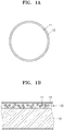
- the separator since the organic particles 11 are mixed with the first binder 12 having a large difference in melting point (Tm) and the porous substrate is coated with the mixture, the first binder 12 may be in a state in which the first binder 12 coats the organic particles 11 or a state in which the organic particles 11 are embedded in the first binder 12.
- FIG. 1A is a schematic view illustrating a separator according to an embodiment where an organic particle 11 in a coating layer is coated with a first binder 12.
- FIG. 1B is a schematic view illustrating a separator according to an embodiment where organic particles 11 are embedded in the first binder 12. Referring to FIG.
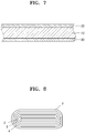
- FIG. 7 is a schematic view illustrating a separator according to an embodiment. Referring to FIG. 7 , the coating layers 20, 30 may be disposed on both surfaces of the porous substrate 10.
- FIG. 2 is an image illustrating the shutdown action of a general separator.
- the separator according to an embodiment is exposed to high temperatures, the organic particles melt and penetrate into the porous substrate, and thus a shutdown of blocking the pores of the porous substrate may occur.
- the first binder having a high melting point in the coating layer may maintain a matrix form of a network structure in a state where pores remain in the sites from which the organic particle was discharged, thereby preventing the collapse of the coating layer.
- the coating layer may be maintained when shutdown occurs at high temperatures, and thus an increase in contact surface of an electrode plate may be inhibited and a rapid increase of temperature and heat generation may be delayed, thereby improving the high-temperature stability of a lithium battery.
- At least one surface of the porous substrate may be coated, and one surface or both surfaces thereof may be coated.
- the organic particle included in the coating layer may have a melting point (Tm) of about 100°C to about 130°C, for example, about 110°C to about 125°C.
- Tm melting point
- the organic particles melt due to sudden heat generation and a change in external environment, so that pores of the separator are blocked to reduce the output of the battery and to make it difficult to use, which may adversely affect battery performance.
- the melting point of the organic particle is higher than about 130°C, melt down of the separator occurs, and thus it is difficult to exert a shutdown effect due to the organic particle. It may be preferable that the organic particle may have a melting point in a range similar to that of a porous substrate.
- the organic particles having a melting point (Tm) of about 100°C to about 130°C applied on the porous substrate are melted after being exposed to a high temperature, such as about 120°C, to block the pores of the porous substrate, thereby inhibiting the movement of current to improve the stability of the lithium battery.
- Tm melting point
- Such an organic particle may include at least one selected from polyethylene (PE), polypropylene (PP), polystyrene (PS), polyvinylidene fluoride (PVDF), polymethyl methacrylate (PMMA), an acrylate compound, polyacrylonitrile (PAN), an azodicarbonamide compound, derivatives thereof, and copolymers thereof.
- the organic particle may include, but is not limited to, at least one selected from polyethylene, polypropylene, polystyrene, and polymethyl methacrylate.
- the organic particle may include polyethylene.
- the above organic particles are merely examples, and other organic particles are also possible.
- the organic particle may have at least one shape selected from a particle shape, a plate shape, a flake shape, and a combination thereof.
- the first binder included in the coating layer may have a melting point higher than the melting point of the organic particles by about 30°C or more.
- the first binder may have a melting point higher than the melting point of the organic particles by about 30°C or more, about 40°C or more, about 50°C or more, about 60°C or more, about 70°C or more, about 80°C or more, about 90°C or more, or about 100°C or more.
- the melting point of the first binder may be about 160°C to about 180°C.
- the melting point of the first binder may be about 165°C to about 175°C.
- the melting point of the first binder may be about 170°C.
- the above melting points are merely examples, and other melting points are also possible.
- the first binder since the first binder has a high melting point within the above range, even when the separator is exposed to high temperatures, the first binder has high heat resistance and may thus maintain a matrix form of a network structure.
- the first binder which is a high-temperature-resistance binder, may include, but is not limited to, at least one selected from a sulfonate compound and a derivative thereof, an acrylamide compound and a derivative thereof, an acrylonitrile compound and a derivative thereof, copolymers thereof, and mixtures thereof.
- the first binder may include a copolymer of a sulfonate compound or a derivative thereof, an acrylamide compound or a derivative thereof, or an acrylonitrile compound or a derivative thereof.
- the first binder may include a (meth)acrylic copolymer including a first structural unit and a second structural unit.
- the first structural unit is derived from (meth)acrylamide
- the second structural unit is selected from structural units derived from (meth)acrylic acid and (meth)acrylate and structural units derived from (meth)acrylamidosulfonic acid and salts thereof.
- the first structural unit may be included in an amount of about 55 mol% to about 95 mol% based on 100 mol% of the (meth)acrylic copolymer, and the second structural unit may be included in an amount of about 5 mol% to about 45 mol% based on 100 mol% of the (meth)acrylic copolymer.
- the first structural unit derived from the (meth)acrylamide includes an amide functional group (-NH 2 ) in the structural unit.
- the -NH 2 functional group may improve adhesive characteristics between the porous substrate and the electrode, and may more firmly fix the inorganic particles in the coating layer by forming a hydrogen bond with an -OH functional group of the inorganic particles to be described later, thereby enhancing the heat resistance of the separator.
- the structural unit derived from the (meth)acrylic acid and (meth)acrylate included in the second structural unit may serve to fix the inorganic particles on the porous substrate, and simultaneously may provide an adhesive force to allows the coating layer to adhere well to the porous substrate and electrode, and may contribute to the improvement of heat resistance and air permeability of the separator.
- the structural unit derived from the (meth)acrylamidosulfonic acid and its salt included in the second structural unit may include a bulky functional group, thereby reducing the mobility of a copolymer including the bulky functional group to enhance the heat resistance of the separator.
- the first structural unit may be included in an amount of about 75 mol% to about 95 mol%, for example, about 80 mol% to about 95 mol%, based on 100 mol% of the (meth)acrylic copolymer.
- the above amounts are merely examples, and other amounts are also possible.
- the structural unit derived from (meth)acrylic acid and (meth)acrylate may be included in an amount of about 0 mol% to about 40 mol% based on 100 mol% of the (meth)acrylic copolymer
- the structural unit derived from the (meth)acrylamidosulfonic acid and its salt may be included in an amount of about 0 mol% to about 10 mol% based on 100 mol% of the (meth)acrylic copolymer.
- the above amounts are merely examples, and other amounts are also possible.
- the structural unit derived from the (meth)acrylamide may be included in an amount of about 90 mol% to about 95 mol% based on 100 mol% of the (meth)acrylic copolymer
- the structural unit derived from the (meth)acrylic acid and (meth)acrylate may be included in an amount of about 0 mol% to about 5 mol% based on 100 mol% of the (meth)acrylic copolymer
- the structural unit derived from the (meth)acrylamidosulfonic acid and its salt may be included in an amount of about 0 mol% to about 5 mol% based on 100 mol% of the (meth)acrylic copolymer.
- the above amounts are merely examples, and other amounts are also possible.
- the first structural unit derived from the (meth)acrylamide may be, for example, represented by Formula 1 below.
- R 1 is hydrogen or a C1 to C6 alkyl group.
- the structural unit derived from the (meth)acrylic acid and (meth)acrylate may be, for example, represented by any one of Formulae 2 and 3 and a combination thereof.
- R 2 and R 3 are each independently hydrogen or a C1 to C6 alkyl group, and R 7 is a substituted or unsubstituted C1 to C20 alkyl group.
- the structural unit derived from (meth)acrylate may be derived from (meth)acrylic acid alkyl ester, (meth)acrylic acid perfluoroalkyl ester, and (meth)acrylate having a functional group in the side chain, and, for example, may be derived from (meth)acrylic acid alkyl ester.
- the number of carbon atoms in the alkyl group or perfluoroalkyl group bonded to a noncarbonyl oxygen atom of the (meth)acrylic acid alkyl ester or (meth)acrylic acid perfluoroalkyl ester may be specifically 1 to 20, more specifically 1 to 10, for example, 1 to 5.
- Some examples of the (meth)acrylic acid alkyl ester having 1 to 5 carbon atoms in the alkyl group or perfluoroalkyl group bonded to the noncarbonyl oxygen atom may include acrylic acid alkyl esters such as methyl acrylate, ethyl acrylate, n-propyl acrylate, isopropyl acrylate, n-butyl acrylate, and t-butyl acrylate; acrylic acid-2-(perfluoroalkyl) ethyl such as acrylic acid-2-(perfluorobutyl) ethyl and acrylic acid-2-(perfluoropentyl) ethyl; methacrylate alkyl esters such as methyl methacrylate, ethyl methacrylate, n-propyl methacrylate, isopropyl methacrylate, n-butyl methacrylate, and t-butyl methacrylate; and methacrylic acid-2-
- Examples of other (meth)acrylic acid alkyl esters may include acrylic acid alkyl esters each having 6 to 18 carbon atoms in the alkyl group bonded to the noncarbonyl oxygen atom, such as n-hexyl acrylate, 2-ethylhexyl acrylate, nonyl acrylate, lauryl acrylate, stearyl acrylate, cyclohexyl acrylate, and isobornyl acrylate; methacrylic acid alkyl esters each having 6 to 18 carbon atoms in the alkyl group bonded to the noncarbonyl oxygen atom, such as n-hexyl methacrylate, 2-ethylhexyl methacrylate, octyl methacrylate, isodecyl methacrylate, lauryl methacrylate, tridecyl methacrylate, stearyl methacrylate, and cyclohexyl methacrylate; acrylic acid-2-(perflu
- the structural unit derived from (meth)acrylic acid or (meth)acrylate may include a structural unit represented by Formula 2 and a structural unit represented by Formula 3, respectively, or may include both a structural unit represented by Formula 2 and a structural unit represented by Formula 3.
- the structural unit represented by Formula 2 and the structural unit represented by Formula 3 may be included at a molar ratio of about 10:1 to about 1:1, for example, about 6:1 to about 1:1, or about 3:1 to about 1:1.
- the above molar ratios are merely examples, and other molar ratios are also possible.
- the structural unit derived from the (meth)acrylamidosulfonic acid and its salt may be a structural unit derived from (meth)acrylamidosulfonic acid or (meth)acrylamidosulfonate, and the (meth)acrylamidosulfonate may be a conjugate base of (meth)acrylamidosulfonic acid, (meth)acrylamidosulfonate, or a derivative thereof.
- the structural unit derived from the (meth)acrylamidosulfonic acid or (meth)acrylamidosulfonate may be represented by any one of Formula 4, Formula 5, Formula 6, and combinations thereof.
- R 4 , R 5 and R 6 are each independently hydrogen or a C1 to C6 alkyl group
- L 1 , L 2 , and L 3 are each independently a substituted or unsubstituted C1 to C10 alkylene group, a substituted or unsubstituted C3 to C20 cycloalkylene group, a substituted or unsubstituted C6 to C20 arylene group, or a substituted or unsubstituted C3 to C20 heterocyclic group
- a, b, and c are each independently an integer of 0 to 2
- M is an alkali metal
- the alkali metal may be, for example, lithium, sodium, potassium, rubidium, or cesium.
- L 1 , L 2 , and L 3 are each independently a substituted or unsubstituted C1 to C10 alkylene group, and a, b and c are each independently 1.
- the structural unit derived from the (meth)acrylamidosulfonic acid and its salt may include each of a structural unit represented by Formula 4, a structural unit represented by Formula 5, and a structural unit represented by Formula 6, or may include two or more thereof together.
- the structure unit may include a structural unit represented by Formula 5.
- the structure unit may include both a structural unit represented by Formula 5 and a structural unit represented by Formula 6.
- the structural unit substituted with an alkali metal (M + ) in the (meth)acrylic copolymer may be included in an amount of about 50 mol% to about 100 mol%, for example,about 60 mol% to about 90 mol%, based on 100 mol% of the total amount of the (meth)acrylamidosulfonic acid structural unit.
- the (meth)acrylic copolymer and the separator including the same may exhibit excellent adhesion, heat resistance, and oxidation resistance.
- the structural unit represented by Formula 5 and the structural unit represented by Formula 6 may be included at a molar ratio of about 10:1 to about 1:2, for example, about 5:1 to about 1:1, or about 3:1 to about 1:1.
- the above molar ratios are merely examples, and other molar ratios are also possible.
- the sulfonic acid group or the sulfonate group in the structural unit derived from the (meth)acrylamidosulfonic acid and a salt thereof may be, for example, vinyl sulfonic acid, allyl sulfonic acid, styrene sulfonic acid, anethol sulfonic acid, acrylamidoalkane sulfonic acid, sulfoalkyl (meth)acrylate, or a functional group derived from a salt thereof.
- the alkane may be a C1 to C20 alkane, a C1 to C10 alkane, or a C1 to C6 alkane
- the alkyl may be a C1 to C20 alkyl, a C1 to C10 alkyl, or a C1 to C6 alkyl.
- the salt refers to a salt composed of the aforementioned sulfonic acid and appropriate ions.
- the ions may be, for example, alkali metal ions, and in this case, the salt may be an alkali metal sulfonic acid salt.
- the acrylamidoalkane sulfonic acid may be, for example, 2-acrylamido-2-methylpropane sulfonic acid
- the sulfoalkyl (meth)acrylate may be, for example, 2-sulfoethyl (meth)acrylate, 3-sulfopropyl (meth)acrylate, or the like.
- the (meth)acrylic copolymer may be represented by Formula 7 below.
- R 8 to R 10 are each independently hydrogen or a methyl group
- R 11 is hydrogen or a C1 to C6 alkyl group
- L 2 is a substituted or unsubstituted C1 to C10 alkylene group, a substituted or unsubstituted C3 to C20 cycloalkylene group, a substituted or unsubstituted C6 to C20 arylene group, or a substituted or unsubstituted C3 to C20 heterocyclic group
- b is an integer of 0 to 2
- M is an alkali metal such as lithium, sodium, potassium, rubidium, or cesium
- each of I, m, and n refers to a molar ratio of each unit.
- 0.05 ⁇ (I+n) ⁇ 0.45 and 0.55 ⁇ m ⁇ 0.95 may be satisfied.
- 0 ⁇ I ⁇ 0.4 and 0 ⁇ n ⁇ 0.1 may be satisfied, and for example, 0.9 ⁇ m ⁇ 0.95, 0 ⁇ I ⁇ 0.05, and 0 ⁇ n ⁇ 0.05 may be satisfied.
- L 2 may be a substituted or unsubstituted C1 to C10 alkylene group, and b may be 1.
- the (meth)acrylic copolymer may further include other units in addition to the above-described units.
- the (meth)acrylic copolymer may further include a unit derived from an alkyl (meth)acrylate, a unit derived from diene, a unit derived from styrene, an ester group-containing unit, a carbonate group-containing unit, or a combination thereof.
- the (meth)acrylic copolymer may have various forms, such as an alternating polymer in which the units are alternately distributed, a random polymer in which the units are randomly distributed, or a graft polymer in which some of the units are grafted.
- the weight average molecular weight of the (meth)acrylic copolymer may be about 350,000 to about 970,000, for example, about 450,000 to about 970,000, or about 450,000 to about 700,000.
- the weight average molecular weight of the (meth)acrylic copolymer and the separator including the same may exhibit excellent adhesion, heat resistance, and air permeability.
- the weight average molecular weight may be a polystyrene-reduced average molecular weight measured using gel permeation chromatography.
- the (meth)acrylic copolymer may be prepared by various known methods such as emulsion polymerization, suspension polymerization, mass polymerization, solution polymerization, and bulk polymerization.
- the content of the first binder may be in a range of about 1 wt% to about 15wt% by weight based on the total weight of the organic particles and the first binder.
- the content of the first binder may be about 3 wt% to about 12 wt%, about 5 wt% to 10 wt%, or 6 wt% to 8 wt% based on the total weight of the organic particles and the first binder.
- a matrix having a network structure surrounding the organic particles may be formed by effectively coating the surface of the organic particle.
- the coating layer includes inorganic particles. Since the coating layer includes the inorganic particles, the possibility of occurrence of a short circuit between the cathode and the anode decreases, and thus stability of the battery may be improved.
- the inorganic particles included in the coating layer may be metal oxide particles, metalloid oxide particles, or a combination thereof.
- the inorganic particles may include alumina, titania, boehmite, barium sulfate, calcium carbonate, calcium phosphate, amorphous silica, crystalline glass particles, kaolin, talc, silica-alumina composite oxide particles, calcium fluoride, lithium fluoride, zeolite, molybdenum sulfide, mica, or magnesium oxide.
- the inorganic particles may include, for example, Al 2 O 3 , SiO 2 , TiO 2 , SnO 2 , CeO 2 , NiO, CaO, ZnO, MgO, ZrO 2 , Y 2 O 3 , SrTiO 3 , BaTiO 3 , MgF 2 , Mg(OH) 2 , or a combination thereof.
- the inorganic particles may include alumina, titania, boehmite, barium sulfate, or a combination thereof.
- the inorganic particles may have a spherical shape, a plate shape, or a fibrous shape, but the shape thereof is not limited thereto, and any shape may be used as long as it may be used in the art.
- Plate-shaped inorganic particles include, for example, alumina and boehmite. In this case, a decrease in area of the separator at high temperature may be further suppressed, a relatively large number of pores may be secured, and characteristics of the lithium battery may be improved during penetration evaluation.
- the aspect ratio of the inorganic particles may be about 1:5 to about 1:100. For example, the aspect ratio thereof may be about 1:10 to about 1:100.
- the aspect ratio thereof may be about 1:5 to about 1:50.
- the aspect ratio thereof may be about 1:10 to about 1:50.
- the ratio of length of major axis to length of minor axis in the flat surface of the plate-shaped inorganic particle may be about 1 to about 3.
- the ratio of length of major axis to length of minor axis in the flat surface thereof may be about 1 to about 2.
- the ratio of length of major axis to length of minor axis in the flat surface thereof may be about 1.
- the aspect ratio and the ratio of length of major axis to length of minor axis may be measured by scanning electron microscope (SEM).
- the average angle of the flat surfaces of the inorganic particles to one surface of the porous substrate may be about 0° to about 30°.
- the angle of flat surface of the inorganic particle to one surface of the porous substrate may converge to about 0°. That is, one surface of the porous substrate and the flat surface of the inorganic particle may be parallel to each other.
- the average angle of the flat surfaces of the inorganic particles to one surface of the porous substrate is within the above range, thermal contraction of the porous substrate may be effectively prevented, and thus a separator having a reduced contraction rate may be provided.
- the average particle diameter of the inorganic particles included in the coating layer may be about 300 nm to about 2 ⁇ m, about 300 nm to about 1.5 ⁇ m, or about 300 nm to about 1.0 ⁇ m.
- the average particle diameter of the inorganic particles is measured using, for example, a measuring apparatus using a laser diffraction method or a dynamic light scattering method.
- the average particle diameter of the inorganic particles is measured using, for example, a laser scattering particle size distribution meter (for example, LA-920, manufactured by Horiba Corporation), and is a value of the median particle diameter (D50) when 50% of the inorganic particles are accumulated from small particles in volume conversion.
- D50 median particle diameter
- both the binding force between the coating layer and the porous substrate and the binding force between the coating layer and the electrode may be improved.
- the separator including the coating layer including the inorganic particles may have an appropriate porosity.
- the inorganic particles may be composed of one type of particle having a uniform particle size distribution, and may be composed of two or more types of particles having different particle size distributions.
- the inorganic particles may be a mixture of two or more types of inorganic particles having different particle size distributions. That is, when the coating layer of the separator includes two or more types of inorganic particles having different particle size distributions, that is, bimodal inorganic particles, inorganic particles having a small particle size may fill the voids between inorganic particles having a large particle size, and thus, a shutdown function may be efficiently performed at high temperature. Through this, it is possible to improve not only the thermal stability of the lithium battery, but also the lifespan characteristics of the lithium battery.
- the content of the organic particles in the coating layer may be more than about 50 wt% based on the total weight of the organic particles and the inorganic particles. Within the above range, even when the separator is exposed to high temperature to allow the organic particles to melt to perform a shutdown action, the network structure of the coating layer having high porosity may be maintained to exhibit high air permeability.
- the content of the organic particles in the coating layer may be about 55 wt% or more, about 60 wt% or more, about 65 wt% or more, or about 70 wt% or more, based on the total weight of the organic particles and the inorganic particles.
- the content of the organic particles in the coating layer may be about 90 wt% or less, about 85 wt% or less, or about 70 wt% or less, based on the total weight of the organic particles and the inorganic particles. Within the above range, high-temperature stability of the battery may be improved.
- the above weight percentages for the content of the organic particles are merely examples, and other weight percentages are also possible.
- the weight ratio of the organic particles and the inorganic particles in the coating layer may be about 51:49 to about 90:10.
- the weight ratio of the organic particles and the inorganic particles may be about 55:45 to about 85:15, or about 60:40 to about 80:20.
- a coating composition having high high-temperature stability may be provided.
- the above weight ratios are merely examples, and other weight ratios are also possible.
- the thickness of the coating layer may be about 0.1 ⁇ m to about 5.0 ⁇ m.
- the thickness of the coating layer may be about 0.5 ⁇ m to about 5.0 ⁇ m.
- the thickness of the coating layer may be about 0.5 ⁇ m to about 4.0 ⁇ m.
- the thickness of the coating layer may be about 1 ⁇ m to about 4.0 ⁇ m.
- the thickness of the coating layer may be about 2.0 ⁇ m to about 4.0 ⁇ m.
- the thickness of the coating layer may be about 2.0 ⁇ m to about 3.5 ⁇ m.
- the thickness of the coating layer may be about 3.0 ⁇ m to about 5.0 ⁇ m.
- the separator may provide an improved shutdown function and air permeability.
- the thickness of the electrode assembly may be minimized, and thus, the capacity per volume of the battery may be maximized.
- the above thicknesses are merely examples, and other thicknesses are also possible.
- the separator may further include an electrode adhesive layer on the coating layer.
- the electrode adhesive layer may impart adhesiveness between the separator and the electrode plate.
- the electrode adhesive layer may include a second binder capable of imparting adhesiveness to the electrode plate.
- the electrode adhesive layer may include an aqueous binder having a glass transition temperature (Tg) of 50°C or higher and being present in the form of particles after coating and drying as the second binder.
- Tg glass transition temperature
- the aqueous binder may include an acrylate or styrene group, but the present disclosure is not limited thereto.
- the second binder a binder having a commonly used binding force may be used.
- the second binder may include, but is not limited to, at least one selected from polyvinylidene fluoride, a polyvinylidene fluoride-hexafluoropropylene copolymer, a polyvinylidene fluoride-trichloroethylene copolymer, a polyvinylidene fluoride-chlorotrifluoroethylene copolymer, polymethyl methacrylate, polyacrylonitrile, polyvinylpyrrolidone, polyvinyl acetate, an ethylene vinyl acetate copolymer, polyethylene oxide, cellulose acetate, cellulose acetate butyrate, cellulose acetate propionate, cyanoethyl pullulan, cyanoethyl polyvinyl alcohol, cyanoethyl cellulose, cyanoethyl sucrose, pullulan, carboxyl methyl cellulose, an acryl
- the electrode adhesive layer may include a fluorine-based binder.
- the fluorine-based binder may be a binder in which some or all of hydrogen atoms connected to carbon is substituted with fluorine atoms.
- the fluorine-based binder may be a polymer including a repeating unit derived from at least one monomer selected from vinylidine fluoride monomers, ethylene tetrafluoride monomers, and propylene hexafluoride monomers.
- the fluorine-based binder may be, for example, a fluorine-based homopolymer or a fluorine-based copolymer.
- the thickness of the electrode adhesive layer may be about 0.1 ⁇ m to about 5.0 ⁇ m.
- the thickness of the electrode adhesive layer may be about 0.1 ⁇ m to about 2.0 ⁇ m.
- the thickness of the electrode adhesive layer may be about 0.1 ⁇ m to about 0.1 ⁇ m.
- the thickness of the electrode adhesive layer may be about 0.2 ⁇ m to about 0.8 ⁇ m.
- the thickness of the electrode adhesive layer may be about 0.3 ⁇ m to about 0.5 ⁇ m.
- the electrode adhesive layer may effectively provide an adhesive force between the coating layer and the electrode plate.
- the above thicknesses of the electrode adhesive layer are merely examples and other thicknesses are also possible.
- the porous substrate included in the separator may be a porous film containing polyolefin.
- Polyolefin has an excellent short-circuit prevention effect, and may also improve battery stability through a shutdown effect.
- the porous substrate may be a film made of a resin such as polyolefin such as polyethylene, polypropylene, polybutene, polyvinyl chloride, or a mixture or copolymer thereof, but the present disclosure is not necessarily limited thereto, and any porous film may be used as long as it is used in the art.
- porous substrate a porous film made of polyolefin resin, a porous film made of polyolefin fiber, a nonwoven fabric containing polyolefin, or an aggregate of insulating material particles may be used.
- a porous film containing polyolefin applicability of a binder solution for forming the coating layer on the porous substrate is excellent, and film thickness of the separator is reduced to increase the ratio of an active material in the battery, thereby increasing the capacity of the battery per unit volume.
- the polyolefin used as the material of the porous substrate may be, for example, a homopolymer such as polyethylene or polypropylene, a copolymer, or a mixture thereof.
- the polyethylene may be low-density polyethylene, medium-density polyethylene, or high-density polyethylene. From the viewpoint of mechanical strength, high-density polyethylene may be used. In addition, two or more types of polyethylene may be mixed for the purpose of imparting flexibility.
- the polymerization catalyst used to prepare polyethylene is not particularly limited, and a Ziegler-Natta catalyst, a Phillips catalyst, or a metallocene catalyst may be used.
- the weight average molecular weight of polyethylene may be about 100,000 to about 12,000,000, for example, about 200,000 to about 3,000,000.
- the above molecular weights of polyethylene are merely examples and other molecular weights of polyethylene are also possible.
- Polypropylene may be a homopolymer, a random copolymer, or a block copolymer, and may be used alone or in combination of two or more.
- the polymerization catalyst is not particularly limited, and a Ziegler-Natta catalyst, a metallocene catalyst, or the like may be used.
- stereoregularity is not particularly limited, and isotactic, syndiotactic, or atactic may be used, but inexpensive isotactic polypropylene may be used.
- polyolefin other than polyethylene or polypropylene, and an additive such as an antioxidant may be added to the polyolefin.
- a multi-layer film of two or more layers including polyolefin such as polyethylene or polypropylene may be used.
- a mixed multi-layer film such as a two-layer film of polyethylene/polypropylene, a three-layer film of polyethylene/polypropylene/polyethylene, or a three-layer film of polypropylene/polyethylene/polypropylene may be used, but the present disclosure is not limited thereto. Any material or composition may be used as long as it may be used as the material or composition of the porous substrate in the art.
- the porous substrate included in the separator may include, for example, a diene-based polymer prepared by polymerizing a monomer composition containing a diene-based monomer.
- the diene-based monomer may be a conjugated diene-based monomer or a nonconjugated diene-based monomer.
- the diene-based monomer may include, but is not limited to, at least one selected from 1,3-butadiene, isoprene, 2-chloro-1,3-butadiene, 2,3-dimethyl-1,3-butadiene, 2-ethyl-1,3-butadiene, 1,3-pentadiene, chloroprene, vinylpyridine, vinyl norbornene, dicyclopentadiene, and 1,4-hexadiene. Any diene-based monomer may be used as long as it may be used in the art.
- the thickness of the porous substrate included in the separator may be about 1 ⁇ m to about 100 ⁇ m.
- the thickness of the porous substrate may be about 1 ⁇ m to about 30 ⁇ m.
- the thickness of the porous substrate may be about 5 ⁇ m to about 20 ⁇ m.
- the thickness of the porous substrate may be about 5 ⁇ m to about 15 ⁇ m.
- the thickness of the porous substrate may be about 5 ⁇ m to about 10 ⁇ m.
- the above thicknesses of the porous substrate are merely examples and other thicknesses are also possible.
- the porosity of the porous substrate included in the separator may be about 5% to about 95%.
- the pore size of the porous substrate in the separator may be about 0.01 ⁇ m to about 50 ⁇ m.
- the pore size of the porous substrate in the separator may be about 0.01 ⁇ m to about 20 ⁇ m.
- the pore size of the porous substrate in the separator may be about 0.01 ⁇ m to about 10 ⁇ m.
- the above pore sizes of the porous substrate are merely examples and other pore sizes are also possible.
- the pore size of the porous substrate is less than about 0.01 ⁇ m, the internal resistance of the lithium battery may increase, and when the pore size of the porous substrate is more than about 50 ⁇ m, the mechanical properties of the porous substrate may be difficult to maintain.
- any method may be used as long as it may be used in the art.
- the separator may be prepared by the process of: preparing a slurry including organic particles, a first binder, and inorganic particles (selectively), applying the slurry onto a porous substrate, and drying and rolling the applied slurry.
- the method of applying the slurry is not particularly limited, and any method may be used as long as it may be used in the art.
- the slurry may be applied by a method such as printing, pressing, press-fitting, roller coating, blade coating, brush coating, dipping coating, spray coating, or flow coating.
- a lithium battery according to another embodiment includes a cathode, an anode, and the above-described separator between the cathode and the anode.
- the lithium battery includes an electrode assembly including a cathode, an anode, and the above-described separator between the cathode and the anode, and the electrode assembly may be wound in the form of a jelly roll. Since the lithium battery includes the above-described separator, defective black spots may be reduced to improve quality, and adhesive force between the electrodes (cathode and anode) and the separator may increase to suppress a change in volume during charging and discharging of the lithium battery. Accordingly, deterioration of the lithium battery accompanying the change in volume of the lithium battery may be suppressed, so that the life characteristics of the lithium battery may be improved.
- the lithium battery may be manufactured, for example, by the following method.
- an anode active material composition in which an anode active material, a conductive material, a binder, and a solvent are mixed is prepared.
- the anode active material composition is directly applied onto a metal current collector to form an anode plate.
- the anode active material composition may be cast on a separate support, and then a film obtained by peeling from the support may be laminated on a metal current collector to form an anode plate.
- the shape of the anode is not limited to the shapes listed above, and may have a shape other than the above shapes.
- the anode active material may be a non-carbon material.
- the anode active material may include at least one selected from a metal alloyable with lithium, an alloy of the metal alloyable with lithium, and an oxide of the metal alloyable with lithium.
- the oxide of the metal alloyable with lithium may include a transition metal oxide or a non-transition metal oxide.
- the metal alloyable with lithium may be Si, Sn, Al, Ge, Pb, Bi, or Sb
- the alloy of the metal alloyable with lithium may be a Si-Y alloy (Y is an alkaline metal, an alkaline earth metal, group 13 to 16 elements, a transition metal, or a combination thereof, not Si), or a Sn-Y alloy (Y is an alkaline metal, an alkaline earth metal, group 13 to 16 elements, a transition metal, or a combination thereof, not Sn).
- the element Y may be Mg, Ca, Sr, Ba, Ra, Sc, Y, Ti, Zr, Hf, Rf, V, Nb, Ta, Db, Cr, Mo, W, Sg, Tc, Re, Bh, Fe, Pb, Ru, Os, Hs, Rh, Ir, Pd, Pt, Cu, Ag, Au, Zn, Cd, B, Al, Ga, Sn, In, Ge, P, As, Sb, Bi, S, Se, Te, Po, or a combination thereof.
- the transition metal oxide may be lithium titanium oxide, vanadium oxide, lithium vanadium oxide, or the like.
- the non-transition metal oxide may be Sn0 2 , SiO x (0 ⁇ x ⁇ 2), or the like.
- the anode active material may include, but is not limited to, at least one selected from Si, Sn, Pb, Ge, Al, SiO x (0 ⁇ x ⁇ 2), SnO y (0 ⁇ y ⁇ 2), Li 4 Ti 5 O 12 , TiO 2 , LiTiO 3 , and Li 2 Ti 3 O 7 .
- Any anode active material may be used as long as it is a non-carbon anode active material used in the art.
- anode active material a composite of the non-carbon anode active material and the carbon-based anode active material may be used, and the carbon-based anode active material may be additionally included in addition to the non-carbon anode active material.
- the carbon-based anode active material may be crystalline carbon, amorphous carbon, or a mixture thereof.
- the crystalline carbon may be graphite such as natural graphite or artificial graphite of an amorphous, plate-like, flake-like, spherical or fibrous form.
- the amorphous carbon may be soft carbon (low-temperature fired carbon), hard carbon, mesophase pitch carbide, or fired coke.
- the above carbon-based anode active materials are merely examples and other carbon-based anode active materials are also possible.
- the conductive material carbon black, graphite fine particles, natural graphite, artificial graphite, acetylene black, ketjen black, carbon fiber, carbon nanotubes, graphene; metal powder, metal fiber or metal tube of copper, nickel, aluminium, or silver; a conductive polymer such as polyphenylene derivatives; or a mixture thereof may be used in combination thereof.
- a conductive polymer such as polyphenylene derivatives; or a mixture thereof
- the present disclosure is not limited thereto, and any conductive material may be used as long as it is used in the art.
- the above-described crystalline carbon-based anode active material may be added as the conductive material.
- a vinylidene fluoride/hexafluoropropylene copolymer polyvinylidene fluoride (PVDF), polyacrylonitrile, polymethyl methacrylate, polytetrafluoroethylene, a styrene-butadiene rubber-based polymer or a mixture thereof may be used.
- PVDF polyvinylidene fluoride
- the present disclosure is not limited thereto, and any binder may be used as long as it is used in the art.
- NMP N-methylpyrrolidone
- acetone or water
- water may be used as the solvent.
- NMP N-methylpyrrolidone
- acetone acetone
- water water
- the present disclosure is not limited thereto, and any solvent may be used as long as it is used in the art.
- the content of the anode active material, the content of the conductive material, the content of the binder, and the content of the solvent are levels generally used in lithium batteries. At least one of the conductive material, the binder, and the solvent may be omitted depending on the use and configuration of the lithium battery.
- the binder used for preparing the anode may be the same as the first binder in the coating composition included in the coating layer of the separator.
- a cathode active material composition in which a cathode active material, a conductive material, a binder, and a solvent are mixed is prepared.
- the cathode active material composition is directly applied onto a metal current collector to form a cathode plate.
- the cathode active material composition may be cast on a separate support, and then a film obtained by peeling from the support may be laminated on a metal current collector to form a cathode plate.
- the cathode active material may include at least one selected from lithium cobalt oxide, lithium nickel cobalt manganese oxide, lithium nickel cobalt aluminium oxide, lithium iron phosphate, and lithium manganese oxide.
- the present disclosure is not limited thereto, and any cathode active material may be used as long as it may be used in the art.
- a compound represented by any one of Formulae of Li a A 1-b B' b D 2 (where, 0.90 ⁇ a ⁇ 1.8, 0 ⁇ b ⁇ 0.5); Li a E 1-b B' b O 2-c D c (where, 0.90 ⁇ a ⁇ 1.8, 0 ⁇ b ⁇ 0.5, 0 ⁇ c ⁇ 0.05); LiE 2-b B' b O 4-c D c (where, 0 ⁇ b ⁇ 0.5, 0 ⁇ c ⁇ 0.05); Li a Ni 1-b-c Co b B' c D ⁇ (where, 0.90 ⁇ a ⁇ 1.8, 0 ⁇ b ⁇ 0.5, 0 ⁇ c ⁇ 0.05, 0 ⁇ ⁇ ⁇ 2); Li a Ni 1-b-c Co b B' c O 2- ⁇ F' ⁇ (where, 0.90 ⁇ a ⁇ 1.8, 0 ⁇ ⁇ 0.5); Li a Ni 1-b
- A is Ni, Co, Mn, or a combination thereof;
- B' is Al, Ni, Co, Mn, Cr, Fe, Mg, Sr, V, a rare earth element, or a combination thereof;
- D is O, F, S, P, or a combination thereof;
- E is Co, Mn, or a combination thereof;
- F' is F, S, P, or a combination thereof;
- G is Al, Cr, Mn, Fe, Mg, La, Ce, Sr, V, or a combination thereof;
- Q is Ti, Mo, Mn, or a combination thereof;
- a compound having a coating layer on the surface of the compound may be used, or a mixture of the compound and a compound having a coating layer may be used.
- the coating layer may include a coating element compound of an oxide of a coating element, a hydroxide of a coating element, an oxyhydroxide of a coating element, an oxycarbonate of a coating element, or a hydroxycarbonate of a coating element.
- the compound constituting this coating layer may be amorphous or crystalline.
- the coating element included in the coating layer Mg, Al, Co, K, Na, Ca, Si, Ti, V, Sn, Ge, Ga, B, As, Zr, or a mixture thereof may be used.
- any coating method may be used as long as this compound may be coated with such elements by a method that does not adversely affect the physical properties of the cathode active material (for example, spray coating, dipping or the like).
- This coating method will be understood by those skilled in the art, so that a detailed description thereof will be omitted.
- the above cathode active materials are merely examples and other cathode active materials are also possible.
- the conductive material, the binder, and the solvent in the cathode active material composition may be the same as those in the anode active material composition. Meanwhile, it is also possible to form pores inside the electrode plate by adding a plasticizer to the cathode active material composition and/or the anode active material composition.
- the content of the cathode active material, the content of the conductive material, the content of a general binder, and the content of the solvent are levels generally used in lithium batteries. At least one of the conductive material, the general binder, and the solvent may be omitted depending on the use and configuration of the lithium battery.
- the binder used for preparing the cathode may be the same as the coating composition included in the coating layer of the separator.
- the composite separator described above is disposed between the cathode and the anode.
- the separator disposed between the cathode and the anode in the electrode assembly including the cathode/separator/anode may include a porous substrate; and a coating layer disposed on both surfaces of the porous substrate, wherein the coating layer includes the above-described coating composition for a separator.
- the separator may be separately prepared and then disposed between the anode and the cathode.
- the separator may be prepared through a formation process in which the electrode assembly including the cathode/separator/anode is wound in the form of a jelly roll, the jelly roll is accompanied in a battery case or a pouch, the jelly roll is thermally softened under pressure in the state of being accompanied in the battery case or the pouch and is pre-charged, and the pre-charged jelly roll is hot-rolled, cold-rolled, and charged and discharged under pressure.
- the electrolyte may be in a liquid or gel state.
- the electrolyte may be an organic electrolyte.
- the electrolyte may be a solid electrolyte.
- the solid electrolyte may be boron oxide, lithium oxynitride, or the like, but is not limited thereto. Any solid elecrolyte may be used as long as it may be used in the art.
- the solid electrolyte may be formed on the anode by a method such as sputtering.
- an organic electrolyte solution may be prepared.
- the organic electrolyte solution may be prepared by dissolving a lithium salt in an organic solvent.
- the organic solvent any organic solvent may be used as long as it may be used in the art.
- the organic solvent may be propylene carbonate, ethylene carbonate, fluoroethylene carbonate, butylene carbonate, dimethyl carbonate, diethyl carbonate, methyl ethyl carbonate, methyl propyl carbonate, ethyl propyl carbonate, methyl isopropyl carbonate, dipropyl carbonate, dibutyl carbonate, benzonitrile, acetonitrile, tetrahydrofuran, 2-methyltetrahydrofuran, ⁇ -butyrolactone, dioxolane, 4-methyldioxolane, N,N-dimethylformamide, dimethylacetamide, dimethylsulfoxide, dioxane, 1,2-dimethoxyethane, sulfolane, dichloroethane, chlorobenzene, nitrobenzene, diethylene glycol, dimethyl ether, or a mixture thereof
- the lithium salt any lithium salt may be used as long as it may be used in the art.
- the lithium salt may be LiPF 6 , LiBF 4 , LiSbF 6 , LiAsF 6 , LiClO 4 , LiCF 3 SO 3 , Li(CF 3 SO 2 ) 2 N, LiC 4 F 9 SO 3 , LiAlO 2 , LiAlCl 4 , LiN(C x F 2x+1 SO 2 )(C y F 2y+1 SO 2 ) (x and y are each a natural number), LiCI, Lil, or a mixture thereof.
- the above lithium salts are merely examples, and other lithium salts are also possible.
- a lithium battery includes a cathode 3, an anode 2, and a composite separator 4.
- the cathode 3, the anode 2, and the separator 4 are wound into an electrode assembly having a flat jelly roll shape and then accommodated in a pouch 7. Subsequently, an organic electrolyte is injected into the pouch 7, and the pouch 7 is sealed to complete the lithium battery.
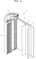
- the lithium battery 1 includes a cathode 3, an anode 2, and a separator 4 between the cathode 3 and the anode 2.
- the cathode 3, the anode 2, and the separator 4 are wound into an electrode assembly having a cylindrical jelly roll shape and then accommodated in a battery case 5. Subsequently, an organic electrolyte is injected into the battery case 5, and the battery case 5 is sealed with a cap assembly 6 to complete the lithium battery 1.
- the battery case 5 may have a cylindrical shape, a rectangular shape, or a thin film shape.
- the lithium battery 1 may be a lithium ion battery.
- the lithium battery 1 may be a lithium polymer battery.
- the lithium battery 1 is suitable for electric vehicles (EV) because it has excellent high rate characteristics and lifespan characteristics.
- the lithium battery 1 is suitable for hybrid vehicles such as plug-in hybrid electric vehicles (PHEV).
- PHEV plug-in hybrid electric vehicles
- polyethylene wax (PE wax) having an average particle diameter (D50) of 0.2 ⁇ m was used.
- poly(acrylic acid-co-acrylamide-co-2-acrylamido-2-methylpropanesulfonic acid) sodium salt was prepared as a copolymer according to the method disclosed in Korean Patent Application No. 10-2018-0111702 , and used.
- the molar ratio of acrylic acid, acrylamide, and 2-acrylamido-2-methylpropanesulfonic acid is 20:75:5.
- the melting point (Tm) of the copolymer is 170°C.
- alumina (AES-11, manufactured by Sumitomo Chemical Co., Ltd.) having an average particle diameter (D50) of 0.4 ⁇ m to 0.6 ⁇ m was used.
- composition for forming a coating layer was gravure-printed on both sides of a polyethylene porous substrate (PE, manufactured by SK Innovation Corporation) having a thickness of 7 ⁇ m to form a coating layer having a total thickness of 3.0 ⁇ m on both sides of the porous substrate.
- PE polyethylene porous substrate
- an electrode adhesive layer containing poly(2-ethylhexylacrylate) as an organic adhesive binder, polyvinylidene fluoride, and water as a solvent was gravure-printed on the coating layer to form an electrode adhesive layer having a thickness of 2 ⁇ m, so as to prepare a separator.
- the separator has a thickness of 12 ⁇ m.
- the polyethylene porous substrate (PE, manufactured by SK Innovation Corporation) itself having a thickness of 7 ⁇ m was used as a separator of Comparative Preparation Example 1.
- a separator was prepared in the same manner as in Preparation Example 1, except that the first binder in Preparation Example 1 was not used, and as organic particles, a slurry for forming a coating layer containing polyethylene (PE) having an average particle diameter (D50) of 0.2 ⁇ m was prepared and used.
- PE polyethylene
- a separator was prepared in the same manner as in Preparation Example 1, except that 28.8 parts by weight of the organic particles, 4 parts by weight of the first binder, and 67.2 parts by weight of the inorganic particles were mixed such that the porosity of the coating layer was 30% to prepare a slurry for forming a coating layer.
- a separator was prepared in the same manner as in Preparation Example 1, except that 48 parts by weight of the organic particles, 4 parts by weight of the first binder, and 48 parts by weight of the inorganic particles were mixed such that the porosity of the coating layer was 50% to prepare a slurry for forming a coating layer.
- a separator was prepared in the same manner as in Preparation Example 1, except that an acrylate-based polymerization binder (BM-2550M, manufactured by Xeon Corporation) was used as low-melting binder instead of the first binder in Preparation Example 1.
- the low-melting binder has a melting point (Tm) of 80°C.
- C1SR graphite particles
- SBR styrene-butadiene rubber
- CMC carboxymethyl cellulose
- the slurry was applied onto a copper current collector having a thickness of 10 ⁇ m using a doctor blade, dried at 100°C for 0.5 hours using a hot air dryer, further dried in vacuum at 120°C for 4 hours, and then roll-pressed to prepare an anode plate.
- 97 wt% of LiCoO 2 , 1.5 wt% of carbon black powder as a conductive material, and 1.5 wt% of Polyvinylidene fluoride (PVdF, SOLVAY) were mixed, introduced into N-methyl-2-pyrrolidone as a solvent, and stirred for 30 minutes using a mechanical stirrer to prepare a cathode active material slurry.
- the slurry was applied onto an aluminium current collector having a thickness of 20 ⁇ m using a doctor blade, dried at 100°C for 0.5 hours using a hot air dryer, further dried in vacuum at 120°C for 4 hours, and then roll-pressed to prepare a cathode plate.
- the separator prepared in Preparation Example 1 was interposed between the above-prepared cathode plate and the above-prepared anode plate, and then wound to prepare an electrode assembly jelly roll.
- the jelly roll was inserted into a pouch, an electrolyte was injected, and then the pouch was vacuum-sealed.
- electrolyte an electrolyte in which LiPF 6 is dissolved in a mixed solvent of ethylene carbonate (EC)/ethyl methyl carbonate (EMC)/diethyl carbonate (DEC) of volume ratio of 3/5/2 was used.
- EC ethylene carbonate
- EMC ethyl methyl carbonate
- DEC diethyl carbonate
- the jelly roll inserted into the pouch was pre-charged up to 50% of SOC while thermally softening the jelly roll at a temperature of 70°C for 1 hour under a pressure of 250kgf/cm 2 .
- the jelly roll was hot-pressed at a temperature of 85°C for 180 seconds under a pressure of 200kgf/cm 2 .
- adhesive force is generated between the anode/cathode and the separator.
- the jelly roll was cold-pressed at a temperature of 22°C to 85°C for 90 seconds under a pressure of 200kgf/cm 2 .
- the binder transitioned from a sol state to a gel state.
- the jelly roll was charged with a constant current of 0.2C rate at a temperature of 45°C for 1 hour under a pressure of 200 kgf/cm 2 until a voltage reached 4.3 V, and was charged with a constant voltage while maintaining the voltage at 4.3 V until the current reached 0.05 C. Subsequently, the cycle of discharging the jelly roll with a constant current of 0.2C was repeated 5 times until the voltage reached 3.0V during discharging to perform the formation step.
- Lithium batteries were manufactured in the same manner as in Example 1, except that the separators prepared in Comparative Preparation Examples 1 to 4 were used, respectively.
- the jelly roll was taken out of each of the pouches of Example 1 and Comparative Examples 1 to 4 that had undergone the formation step, and the separator was separated from the jelly roll, and penetration characteristics of the separator were evaluated. Results thereof are shown in Table 1 below. The degree and probability of occurrence of abnormality were evaluated according to a phenomenon observed after performing a nail test on each separator. In the case of L4-3 and L6, it was evaluated that abnormality occurred.
- FIGS. 3 and 4 are views of FIG. 4 .
- a coating layer (that is, a shutdown layer) including organic particles and inorganic particles is formed on the separator prepared in Preparation Example 1.
- FIG. 6 is an SEM image of the separator prepared in Comparative Preparation Example 5 after being left at high temperature under the same conditions.
- the separator according to one aspect may maintain the coating layer of a network structure even at high temperatures, and thus, when a shutdown occurs, a rapid increase in temperature and heat generation is delayed, thereby improving high-temperature stability of a lithium battery.
Applications Claiming Priority (1)
| Application Number | Priority Date | Filing Date | Title |
|---|---|---|---|
| KR1020200044788A KR102629464B1 (ko) | 2020-04-13 | 2020-04-13 | 세퍼레이터 및 이를 채용한 리튬 전지 |
Publications (2)
| Publication Number | Publication Date |
|---|---|
| EP3896782A2 true EP3896782A2 (fr) | 2021-10-20 |
| EP3896782A3 EP3896782A3 (fr) | 2021-10-27 |
Family
ID=75529792
Family Applications (1)
| Application Number | Title | Priority Date | Filing Date |
|---|---|---|---|
| EP21168221.6A Pending EP3896782A3 (fr) | 2020-04-13 | 2021-04-13 | Séparateur et batterie au lithium l'incluant |
Country Status (4)
| Country | Link |
|---|---|
| US (1) | US20210320378A1 (fr) |
| EP (1) | EP3896782A3 (fr) |
| KR (1) | KR102629464B1 (fr) |
| CN (1) | CN113540690B (fr) |
Cited By (1)
| Publication number | Priority date | Publication date | Assignee | Title |
|---|---|---|---|---|
| CN114466577A (zh) * | 2022-04-11 | 2022-05-10 | 浙江德塔森特数据技术有限公司 | 一种多功能的数据机房采控方法及设备 |
Families Citing this family (1)
| Publication number | Priority date | Publication date | Assignee | Title |
|---|---|---|---|---|
| CN114976378B (zh) * | 2022-04-29 | 2023-05-12 | 楚能新能源股份有限公司 | 一种复合隔热板及其制备方法和应用 |
Citations (1)
| Publication number | Priority date | Publication date | Assignee | Title |
|---|---|---|---|---|
| KR20180111702A (ko) | 2017-03-31 | 2018-10-11 | 오티스 엘리베이터 컴파니 | 방문객 제어를 위한 그룹 액세스 관리 |
Family Cites Families (32)
| Publication number | Priority date | Publication date | Assignee | Title |
|---|---|---|---|---|
| JP2005276503A (ja) * | 2004-03-23 | 2005-10-06 | Mitsubishi Electric Corp | 電池用セパレータ及びそれを用いた電池 |
| JP5193998B2 (ja) * | 2007-03-15 | 2013-05-08 | 日立マクセル株式会社 | 電気化学素子用セパレータ、電気化学素子用電極および電気化学素子 |
| JP5228388B2 (ja) * | 2007-07-12 | 2013-07-03 | 東レ株式会社 | 多孔性フィルムおよび蓄電デバイス |
| JP5189459B2 (ja) * | 2008-10-27 | 2013-04-24 | 株式会社クラレ | リチウム電池用セパレータ及びそれを用いたリチウム電池 |
| US8557437B2 (en) * | 2009-03-25 | 2013-10-15 | Tdk Corporation | Electrode comprising protective layer for lithium ion secondary battery and lithium ion secondary battery |
| KR101055536B1 (ko) * | 2009-04-10 | 2011-08-08 | 주식회사 엘지화학 | 다공성 코팅층을 포함하는 세퍼레이터, 그 제조방법 및 이를 구비한 전기화학소자 |
| JP2013191391A (ja) * | 2012-03-13 | 2013-09-26 | Nissan Motor Co Ltd | 二次電池 |
| TWI618279B (zh) * | 2012-04-04 | 2018-03-11 | Asahi Kasei Fibers Corp | 分隔件材料 |
| JP2014149935A (ja) * | 2013-01-31 | 2014-08-21 | Nippon Zeon Co Ltd | 二次電池用セパレータ、二次電池用セパレータの製造方法及び二次電池 |
| JP2014179321A (ja) * | 2013-03-13 | 2014-09-25 | Samsung Sdi Co Ltd | セパレータおよびこれを含むリチウム二次電池 |
| JP2014179279A (ja) * | 2013-03-15 | 2014-09-25 | Japan Vilene Co Ltd | 電気化学素子用セパレータ |
| US10038174B2 (en) * | 2013-04-16 | 2018-07-31 | Samsung Sdi Co., Ltd. | Separator and lithium battery including the separator |
| CN103247770A (zh) * | 2013-04-25 | 2013-08-14 | 东莞新能源科技有限公司 | 一种锂离子电池隔膜及其制备方法 |
| CN104124414B (zh) * | 2013-04-28 | 2017-06-20 | 华为技术有限公司 | 一种锂离子电池复合电极片及其制备方法和锂离子电池 |
| KR101759336B1 (ko) * | 2013-10-02 | 2017-07-18 | 주식회사 엘지화학 | 다공성 코팅층을 갖는 다공성 분리막 및 이의 제조방법 |
| US9825271B2 (en) * | 2013-11-05 | 2017-11-21 | Lg Chem, Ltd. | Separator for electrochemical device |
| US9905824B2 (en) * | 2013-12-17 | 2018-02-27 | Lg Chem, Ltd. | Separator for electrochemical device |
| US10002719B2 (en) * | 2014-04-21 | 2018-06-19 | Lg Chem, Ltd. | Separator having binder layer, and electrochemical device comprising the separator and method of preparing the separator |
| KR102253020B1 (ko) * | 2014-11-19 | 2021-05-14 | 삼성에스디아이 주식회사 | 리튬 이차 전지용 세퍼레이터 및 이를 포함하는 리튬 이차 전지 |
| US10777801B2 (en) * | 2015-08-25 | 2020-09-15 | Lg Chem, Ltd. | Complex separator for electrochemical element, comprising bonding layer, and electrochemical element comprising same |
| US20180294455A1 (en) * | 2015-10-30 | 2018-10-11 | Ube Industries, Ltd. | Porous film and electricity storage device |
| KR102134424B1 (ko) * | 2015-11-11 | 2020-07-15 | 주식회사 엘지화학 | 전극접착층을 구비한 세퍼레이터 및 이를 포함하는 전기화학소자 |
| EP3439073B1 (fr) * | 2016-03-29 | 2023-10-18 | Toray Industries, Inc. | Séparateur pour batterie secondaire, et batterie secondaire |
| CN107785519A (zh) * | 2016-08-29 | 2018-03-09 | 比亚迪股份有限公司 | 一种聚合物复合膜及其制备方法以及包括其的锂离子电池 |
| KR102612838B1 (ko) * | 2017-08-03 | 2023-12-13 | 데이진 가부시키가이샤 | 비수계 이차전지용 세퍼레이터, 및 비수계 이차전지 |
| KR102233770B1 (ko) * | 2018-02-01 | 2021-03-30 | 삼성에스디아이 주식회사 | 분리막, 이를 채용한 리튬전지 및 분리막의 제조 방법 |
| KR102210884B1 (ko) * | 2018-02-26 | 2021-02-02 | 삼성에스디아이 주식회사 | 분리막, 이의 제조방법 및 이를 포함하는 리튬전지 |
| KR102209826B1 (ko) * | 2018-03-06 | 2021-01-29 | 삼성에스디아이 주식회사 | 분리막, 이의 제조방법 및 이를 포함하는 리튬전지 |
| CN108550766A (zh) * | 2018-04-26 | 2018-09-18 | 沧州明珠塑料股份有限公司 | 一种热关断耐高温高安全涂布改性隔膜及其制备方法 |
| KR101996642B1 (ko) * | 2018-07-13 | 2019-07-04 | 주식회사 엘지화학 | 저저항 코팅층을 포함하는 전기화학소자용 분리막 및 이를 제조하는 방법 |
| KR102279515B1 (ko) * | 2018-09-03 | 2021-07-20 | 삼성에스디아이 주식회사 | 리튬 이차 전지용 분리막 및 이를 포함하는 리튬 이차 전지 |
| KR20200032542A (ko) * | 2018-09-18 | 2020-03-26 | 삼성에스디아이 주식회사 | 리튬 이차 전지용 분리막 및 이를 포함하는 리튬 이차 전지 |
-
2020
- 2020-04-13 KR KR1020200044788A patent/KR102629464B1/ko active IP Right Grant
-
2021
- 2021-04-09 US US17/226,999 patent/US20210320378A1/en active Pending
- 2021-04-13 CN CN202110393293.4A patent/CN113540690B/zh active Active
- 2021-04-13 EP EP21168221.6A patent/EP3896782A3/fr active Pending
Patent Citations (1)
| Publication number | Priority date | Publication date | Assignee | Title |
|---|---|---|---|---|
| KR20180111702A (ko) | 2017-03-31 | 2018-10-11 | 오티스 엘리베이터 컴파니 | 방문객 제어를 위한 그룹 액세스 관리 |
Cited By (1)
| Publication number | Priority date | Publication date | Assignee | Title |
|---|---|---|---|---|
| CN114466577A (zh) * | 2022-04-11 | 2022-05-10 | 浙江德塔森特数据技术有限公司 | 一种多功能的数据机房采控方法及设备 |
Also Published As
| Publication number | Publication date |
|---|---|
| EP3896782A3 (fr) | 2021-10-27 |
| KR20210126992A (ko) | 2021-10-21 |
| CN113540690B (zh) | 2024-01-05 |
| CN113540690A (zh) | 2021-10-22 |
| US20210320378A1 (en) | 2021-10-14 |
| KR102629464B1 (ko) | 2024-01-25 |
Similar Documents
| Publication | Publication Date | Title |
|---|---|---|
| KR102210884B1 (ko) | 분리막, 이의 제조방법 및 이를 포함하는 리튬전지 | |
| KR101785267B1 (ko) | 리튬전지 | |
| JP6772310B2 (ja) | 分離膜、それを採用したリチウム電池、及び該分離膜の製造方法 | |
| KR20190105881A (ko) | 분리막, 이의 제조방법 및 이를 포함하는 리튬전지 | |
| US9105909B2 (en) | Separator, lithium battery including the separator, and method of preparing the separator | |
| KR102426253B1 (ko) | 분리막, 이를 채용한 리튬전지 및 분리막의 제조 방법 | |
| KR102570263B1 (ko) | 리튬 전지용 전극, 이를 포함하는 리튬 전지, 및 상기 리튬 전지의 제조방법 | |
| EP4071873B1 (fr) | Séparateur et batterie au lithium comprenant un séparateur | |
| KR102331720B1 (ko) | 분리막 및 이를 채용한 리튬전지 | |
| EP3896782A2 (fr) | Séparateur et batterie au lithium l'incluant | |
| KR20190049327A (ko) | 분리막 일체형 전극 어셈블리, 그 제조 방법 및 이를 포함하는 리튬이온이차전지 | |
| KR102572651B1 (ko) | 복합 세퍼레이터, 이를 채용한 리튬 전지, 및 이의 제조방법 | |
| KR20210113877A (ko) | 복합 세퍼레이터 제조 방법, 복합세퍼레이터 및 이를 채용한 리튬 전지 | |
| EP4250459A1 (fr) | Batterie au lithium et son procédé de fabrication | |
| US20240014511A1 (en) | Separator and lithium battery employing same | |
| JP2024514641A (ja) | リチウム二次電池用分離膜、それを含むリチウム二次電池、及び該リチウム二次電池用分離膜の製造方法 | |
| KR20220125575A (ko) | 분리막 및 이를 채용한 리튬 전지 |
Legal Events
| Date | Code | Title | Description |
|---|---|---|---|
| PUAI | Public reference made under article 153(3) epc to a published international application that has entered the european phase |
Free format text: ORIGINAL CODE: 0009012 |
|
| STAA | Information on the status of an ep patent application or granted ep patent |
Free format text: STATUS: REQUEST FOR EXAMINATION WAS MADE |
|
| PUAL | Search report despatched |
Free format text: ORIGINAL CODE: 0009013 |
|
| 17P | Request for examination filed |
Effective date: 20210413 |
|
| AK | Designated contracting states |
Kind code of ref document: A2 Designated state(s): AL AT BE BG CH CY CZ DE DK EE ES FI FR GB GR HR HU IE IS IT LI LT LU LV MC MK MT NL NO PL PT RO RS SE SI SK SM TR |
|
| AK | Designated contracting states |
Kind code of ref document: A3 Designated state(s): AL AT BE BG CH CY CZ DE DK EE ES FI FR GB GR HR HU IE IS IT LI LT LU LV MC MK MT NL NO PL PT RO RS SE SI SK SM TR |
|
| RIC1 | Information provided on ipc code assigned before grant |
Ipc: H01M 10/052 20100101ALN20210920BHEP Ipc: H01M 50/489 20210101ALI20210920BHEP Ipc: H01M 50/446 20210101AFI20210920BHEP |