EP3884481B1 - Smartboard und set zum digitalisieren von workshop-ergebnissen - Google Patents
Smartboard und set zum digitalisieren von workshop-ergebnissen Download PDFInfo
- Publication number
- EP3884481B1 EP3884481B1 EP19805959.4A EP19805959A EP3884481B1 EP 3884481 B1 EP3884481 B1 EP 3884481B1 EP 19805959 A EP19805959 A EP 19805959A EP 3884481 B1 EP3884481 B1 EP 3884481B1
- Authority
- EP
- European Patent Office
- Prior art keywords
- paper
- smartboard
- sheet
- clipboard
- support
- Prior art date
- Legal status (The legal status is an assumption and is not a legal conclusion. Google has not performed a legal analysis and makes no representation as to the accuracy of the status listed.)
- Active
Links
Images

Classifications
-
- G—PHYSICS
- G09—EDUCATION; CRYPTOGRAPHY; DISPLAY; ADVERTISING; SEALS
- G09F—DISPLAYING; ADVERTISING; SIGNS; LABELS OR NAME-PLATES; SEALS
- G09F1/00—Cardboard or like show-cards of foldable or flexible material
-
- G—PHYSICS
- G09—EDUCATION; CRYPTOGRAPHY; DISPLAY; ADVERTISING; SEALS
- G09B—EDUCATIONAL OR DEMONSTRATION APPLIANCES; APPLIANCES FOR TEACHING, OR COMMUNICATING WITH, THE BLIND, DEAF OR MUTE; MODELS; PLANETARIA; GLOBES; MAPS; DIAGRAMS
- G09B15/00—Teaching music
- G09B15/02—Boards or like means for providing an indication of notes
- G09B15/023—Electrically operated
-
- G—PHYSICS
- G06—COMPUTING OR CALCULATING; COUNTING
- G06K—GRAPHICAL DATA READING; PRESENTATION OF DATA; RECORD CARRIERS; HANDLING RECORD CARRIERS
- G06K7/00—Methods or arrangements for sensing record carriers, e.g. for reading patterns
- G06K7/10—Methods or arrangements for sensing record carriers, e.g. for reading patterns by electromagnetic radiation, e.g. optical sensing; by corpuscular radiation
- G06K7/10009—Methods or arrangements for sensing record carriers, e.g. for reading patterns by electromagnetic radiation, e.g. optical sensing; by corpuscular radiation sensing by radiation using wavelengths larger than 0.1 mm, e.g. radio-waves or microwaves
- G06K7/10316—Methods or arrangements for sensing record carriers, e.g. for reading patterns by electromagnetic radiation, e.g. optical sensing; by corpuscular radiation sensing by radiation using wavelengths larger than 0.1 mm, e.g. radio-waves or microwaves using at least one antenna particularly designed for interrogating the wireless record carriers
- G06K7/10336—Methods or arrangements for sensing record carriers, e.g. for reading patterns by electromagnetic radiation, e.g. optical sensing; by corpuscular radiation sensing by radiation using wavelengths larger than 0.1 mm, e.g. radio-waves or microwaves using at least one antenna particularly designed for interrogating the wireless record carriers the antenna being of the near field type, inductive coil
-
- G—PHYSICS
- G06—COMPUTING OR CALCULATING; COUNTING
- G06K—GRAPHICAL DATA READING; PRESENTATION OF DATA; RECORD CARRIERS; HANDLING RECORD CARRIERS
- G06K7/00—Methods or arrangements for sensing record carriers, e.g. for reading patterns
- G06K7/10—Methods or arrangements for sensing record carriers, e.g. for reading patterns by electromagnetic radiation, e.g. optical sensing; by corpuscular radiation
- G06K7/10009—Methods or arrangements for sensing record carriers, e.g. for reading patterns by electromagnetic radiation, e.g. optical sensing; by corpuscular radiation sensing by radiation using wavelengths larger than 0.1 mm, e.g. radio-waves or microwaves
- G06K7/10366—Methods or arrangements for sensing record carriers, e.g. for reading patterns by electromagnetic radiation, e.g. optical sensing; by corpuscular radiation sensing by radiation using wavelengths larger than 0.1 mm, e.g. radio-waves or microwaves the interrogation device being adapted for miscellaneous applications
- G06K7/10376—Methods or arrangements for sensing record carriers, e.g. for reading patterns by electromagnetic radiation, e.g. optical sensing; by corpuscular radiation sensing by radiation using wavelengths larger than 0.1 mm, e.g. radio-waves or microwaves the interrogation device being adapted for miscellaneous applications the interrogation device being adapted for being moveable
-
- G—PHYSICS
- G09—EDUCATION; CRYPTOGRAPHY; DISPLAY; ADVERTISING; SEALS
- G09F—DISPLAYING; ADVERTISING; SIGNS; LABELS OR NAME-PLATES; SEALS
- G09F1/00—Cardboard or like show-cards of foldable or flexible material
- G09F1/10—Supports or holders for show-cards
-
- G—PHYSICS
- G09—EDUCATION; CRYPTOGRAPHY; DISPLAY; ADVERTISING; SEALS
- G09F—DISPLAYING; ADVERTISING; SIGNS; LABELS OR NAME-PLATES; SEALS
- G09F7/00—Signs, name or number plates, letters, numerals, or symbols; Panels or boards
- G09F7/02—Signs, plates, panels or boards using readily-detachable elements bearing or forming symbols
- G09F7/04—Signs, plates, panels or boards using readily-detachable elements bearing or forming symbols the elements being secured or adapted to be secured by magnetic means
Definitions
- the invention relates to a clipboard designed as a base for a sheet of paper with a fastening for it, the base being provided with at least one, preferably two, RFID transponders, and at least one sheet of paper with an RFID transponder, with one RFID transponder each of the base and the paper are placed in close communication with each other when the sheet of paper is fixed to the fixture
- Whiteboards, pin boards, blackboards or tables serve as working documents for workshops. For example, on such traditional work surfaces as whiteboards or bulletin boards, participants jot down their ideas on slips of paper and attach them to them for all to see. An evaluation is then carried out, double mentions are removed, similar ones are bundled, important ones are embellished with further mentions. Depending on the purpose of the workshop, sequences are established and/or priorities are set and tasks and responsibilities are assigned at the end.
- the clipboard comprises a marking on the base, which indicates exactly where the paper is to be placed, and a large number of switches on the base, which are preferably arranged in a matrix, with the sheet containing various information, instructions and/or selections -variants, as well as several marking fields, which are placed respectively at the locations of the clipboard switches when the sheet is fixed on the marking of the base.
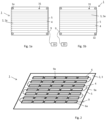
- Figures 1a and 1b each shows a smartboard 1 for digitizing workshop results, comprising a first surface 2 and a second surface 3, which are configured parallel to one another.
- Such a smartboard 1 can either be placed on a table or hung on a wall or on a conventional whiteboard, for which purpose eyelets 1a attached to the smartboard 1 can be used. You can work horizontally or vertically on Smartboard 1.
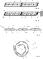
- Figures 3a and 3b show an enlargement of individual segments of it. Between these surfaces 2, 3 a multiplicity of pockets 4 are arranged parallel to one another and are connected to one another at joints 5.
- FIG. In each pocket 4 there are one or more printed circuit boards 6 which are electrically connected to one another and comprise a large number of NFC receivers 7 in an array.
- a plurality of magnets 8 in the form of ferromagnets or permanent magnets arranged in an array.
- NFC receivers 7 and the magnets 8 are preferably arranged alternately in the array.
- printed circuit boards 6 can be plugged together within a pocket 4, for example, at electrical connections 9a in order to be electronically contacted with one another.
- 4 shows a cross section of individual pockets 4 in the area of the printed circuit boards 6 and the magnets 8.
- the printed circuit boards 6 of adjacent pockets 4 are connected to one another at electronic connections 9a, preferably in a meandering fashion, as in 2 shown.
- a first of the printed circuit boards 6a is provided with a connection 9 for connection to a power supply 10 and for data output, in order to transmit data to a computer 10, for example.
- switches 15 that can be triggered by a user can be arranged in the pockets 4, preferably pressure switches.
- each NFC receiver 7 is assigned its own switch 15, as in Figure 3b shown. Depending on the structure of the switch 15, it can be designed in such a way that it can be actuated either from the first and/or from the second surface 2, 3 by a user pressing it, or two opposite switches 15 can be arranged, as in the right part of 4 shown.
- Each switch 15 is also connected to the terminal 9 for data output.
- the smartboard 1 can be rolled up into a roll 11 with an axis 12 parallel to the long pockets 4, as shown in FIG figure 5 shown.
- the pockets 4 preferably have a pressure-resistant housing 14 in which the printed circuit boards 6 and the magnets 8 are arranged in a protected manner.
- the switches 15 are finally attached to these housings 14 so that they can be actuated from the outside, for example by pressing.
- At least the first surface 2 consists of a flexible material, in particular a textile material such as a felt mat 2a, so that this surface 2 can be pierced by a pin or a needle. Information can be easily written on slips of paper and pinned to the Smartboard 1.
- At least the second surface 3 can consist of a pressure-resistant material, preferably plastic plates 3a. This is preferably designed with few gaps when the smart board 1 is completely unwound. This second surface 3 can easily be written on with washable markers and self-adhesive notes can be attached to it. It is also possible to design both surfaces 2, 3 in the same way.
- Smartboard 1 Information can be attached to the Smartboard 1 in various ways.
- the Smartboard 1 described or equipped can be expanded in a modular manner by further modules 17, 19, 21, 23, 25, 28 described here, which form a set 16 together with the Smartboard 1.
- each of these modules 17, 19, 21, 23, 25, 28 can also be used alone or in connection with other such modules 17, 19, 21, 23, 25, 28 or with components not mentioned here.
- the purpose should always be to organize, save or forward information in group work or project work. A coach usually leads and accompanies such group work and explains to the participants how to work with the Smartboard 1 and the modules 17, 21, 23, 25, 28.
- information can be written to suitable, magnetically adhering modules 17, 19, 21, 23, 25 that adhere to the magnets 8 in the smart board 1. They can also be superimposed, grouped together, or placed in a logical sequence. Additional information can also be attached directly to the Smartboard 1.
- a set 16 includes, for example, a smartboard 1 and two or more objects 17 as modules, as shown in Fig. 6 or 7 . As a rule, a multiplicity of such objects 17 are used.
- Each of these objects 17 includes at least one magnet 8 in the form of a permanent magnet or ferromagnet and at least one, preferably two, RFID transponders 18.
- the objects 17 can optionally also include a switch 15, in particular a pressure switch.
- the cards 19 have the size and shape of credit cards or business cards. In a preferred embodiment, they have a coding 20, for example in the form of notches. Such codes 20 can help to separate cards 19 that belong to a group and all have the same code 20 from other cards 19.
- the cards 19 are placed in boxes provided for this purpose, which have grooves on the bottom that correspond to the notches 20 of a respective group. Cards 19 that do not belong to this group and therefore have a different coding 20 are present at at least one of the grooves and thereby rise above the other cards 19 that have a notch 20 at these points. So they can be sorted out easily.
- An additional color coding on the side can, for example, mark the sequence of the cards 19 if each subsequent card 19 has the color marking slightly offset compared to its predecessor card. It is very easy to check the order.
- the objects 17 can be designed as a box 23 with a housing 24 and an interior space 24, as in 7 shown.
- a can 23 has a better grip.
- the RFID transponder(s) 18 and the magnet 8 can be accommodated in the interior 24 of each can 23 , and a switch 15 can also be attached to the can 23 .
- the magnet 8 is preferably designed in the form of a permanent magnet and is mounted in the interior space 24 in such a way that it can align itself freely. Several magnets 8 can also be provided.
- Further suitable electronic components can be arranged on a printed circuit board 6 .
- the box 23 can have an LED 31 which gives feedback after the switch 15 has been actuated. The supply for this can run via the RFID transponders 18 from the smart board 1 .
- the boxes 23 protect the components arranged in the interior 24 from the effects of external forces and from contamination.
- Such objects 17 or cards 19 can already be labeled or can be labeled during work. Thanks to their magnets 8, they adhere to the Smartboard 1. Their RFID transponders 18 correspond to the NFC receivers 7. This allows a computer 10 connected to the Smartboard 1 to transmit the ID number of the card 19 and the position on the Smartboard 1 to which she is liable.
- the card 19 can be assigned further properties that are stored in a database to which the computer 10 has access. In addition, further actions can be triggered if, for example, a switch 15 on the smartboard 1 is actuated before a card 19 is attached to it. Visual or other information can be retrieved or assignments to the ID number of the respective card 19 can be made.
- an assignment can be created such as "the next photo taken with a camera assigned to the smartboard 1 is linked in a database with the ID number of the card 19 that is stuck on the switch 15".
- the image of a person who is to be used as a project manager, or an image of an architectural model that is to be implemented, can be assigned to a card 19 .
- the switch 15 is actuated again, the corresponding image can be shown on a display. If several cards 19 are arranged one above the other, the images of all these cards 19 are displayed accordingly.
- a management system can contain a large number of moderation programs that list different instructions for working with the Smartboard 1 and the various objects 17, 19, 21, 23, 25, 28. Accordingly, a management system may contain one or more packs of cards 19 include different groups, the ID numbers of the individual cards 19 are already recorded in a database and correlated with certain information.
- Another set 16 again includes a smartboard 1 and objects 17, as described above. It also includes one or more connecting elements 21, shown in Figures 8a and 8b .
- a connecting element 21 comprises two objects 17 connected to one another by a connecting band 22.
- the connecting band 22 merely represents a visual and structural connection of the objects 17; it can be elastic.
- the objects 17 can be designed as cards 19 or as boxes 23, as in Figure 8a shown. If the two end points of the connecting strip 22 with the magnets 8 of the objects 17 are placed on the smartboard 1, the two positions of these end points can be assigned to one another. This can mean a chronological order, a hierarchy, a affiliation or the like.
- the cans 23 can as in 7 be configured as described. In particular, they can have a housing 14 with an interior space 24 .
- one or two further such objects 17 are slidably attached to the connecting band 22 . If only one other object 17 is attached, it can be understood as a percentage, for example: placing the movable object 17 in the middle between the ends of the connecting band 22 means 50%, moving it in half towards one end corresponds to 25% or 75%, depending on the predefined starting position. The scaling cannot be resolved as finely as desired, the placement is recorded by the NFC receiver 7 based on the placement of the RFID transponders 18 .
- the objects 17 of a connecting element 21 can optionally be displayed as a card 19, as in 6 , or be designed as a box 23 with an interior 24, as in 7 described.
- a set 16 or a smartboard 1 includes an object 17 in the form of a smartbook 25, shown in 9 .
- a Smartbook 25 comprises a plate 26, the length of which extends over two or more array spacings of switches 15 in the smartboard 1 and/or the width of which extends over two or more pockets 4.
- the plate 26 has several magnets 8 arranged in an array or grid in the form of ferromagnets or permanent magnets and at least two RFID transponders 18 , similar to the card 19 6 .
- a multi-page booklet 27 is attached to her, the pages of which are provided with instructions and selection variants 27a.
- a switch 15 of the smartboard 1 can be assigned to each of these variants 27a, which switch is arranged directly around the smartbook 25 when it is attached to the smartboard 1 during use. When these switches 15 are actuated, additional information is retrieved, which in turn can contain instructions. In addition, a switch 15 can be defined, which is then to be actuated when the page is closed. Then the page is turned and the instructions on the next page are followed after further additional information has been retrieved.
- Such smartbooks 25 can be made for various workshops or projects and can guide the user or users through a process, for example a decision-making process.
- the various aspects can each be highlighted on one side and the variants that are available to the user to choose from can be assigned to the surrounding switches 15 on the smartboard 1.
- the smartboard 1 recognizes the position of the smartbook 25 through the two RFID transponders, which correspond to the NFC receivers on the smartboard 1.
- all information entered by the user on the smartboard by actuating the switch 15 is sent to the computer and processed there.
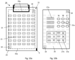
- a clipboard 28 according to Figure 10a be used alone or as an additional module with the Smartboard 1 or with a named Set 16.
- a clipboard 28 according to the invention comprises a base 29 with attachment 29a for a sheet of paper 30, as shown in Figure 10b is shown, and is provided with at least one, preferably two, RFID transponders 18 .
- the sheet of paper 30 itself also includes one or two RFID transponders 18, with at least one RFID transponder 18 each of the base 29 and the sheet of paper 30 being arranged in close communication with one another when the sheet of paper 30 is fixed to the attachment 29a.
- the base 29 has a marking 30a, which indicates where exactly the sheet of paper 30 is to be placed.
- the base 29 also includes a plurality of switches 15, preferably arranged in a matrix.
- the sheet of paper 30 may also be part of a collection of pre-made sheets of paper 30.
- Each of these sheets 30 is provided with various information, instructions and selection variants 27a and with a plurality of identification fields 15a, which are respectively arranged at the locations of the switches 15 of the clipboard 28 when the sheet 30 is attached to the marking 30a of the base 29.
- the user actuates the corresponding switches 15, for example by pressing them.
- the identification fields 15a which are selectively operable, are indicated by circles placed under the letters A, B and C. Further identification fields 15a are located at the positions of the crosses in the table below.
- the user activates the appropriate switches 15 on the clipboard 28, as appropriate, by pressing the identifier fields 15a.
- Each switch 15 is preferably designed as a push button.
- the clipboard 28 can also include a connection 9 which can also be a wireless interface with which the recorded data can be transmitted to a computer 10 .
- the clipboard 28 can also include one or more LEDs 31 in order to provide feedback for actions taken or to obtain information. For example, it can be indicated by the LED 31 lighting up that information about a certain fact is being displayed on a screen.
- the set 16 comprising a smartboard 1 and an object 17, the object being a card 19, a can 23, a connecting element 21 or a clipboard 28, is not marked as such in the figures.
- Objects 19, 21, 23 and 28 are shown alone, without smartboard 1. Only set 16, comprising a smartboard 1 and a smartbook 25, is in 9 shown. According to the invention, the object 28 described here according to this invention can also be used alone or in combination with other objects 17, 19, 21, 23, 25 and 28.
Landscapes
- Engineering & Computer Science (AREA)
- Physics & Mathematics (AREA)
- General Physics & Mathematics (AREA)
- Theoretical Computer Science (AREA)
- Health & Medical Sciences (AREA)
- Toxicology (AREA)
- General Health & Medical Sciences (AREA)
- Computer Vision & Pattern Recognition (AREA)
- Artificial Intelligence (AREA)
- Electromagnetism (AREA)
- Computer Networks & Wireless Communication (AREA)
- Educational Technology (AREA)
- Educational Administration (AREA)
- Business, Economics & Management (AREA)
- Multimedia (AREA)
- Credit Cards Or The Like (AREA)
- Drawing Aids And Blackboards (AREA)
- Sheet Holders (AREA)
- Casings For Electric Apparatus (AREA)
- Toys (AREA)
- Electrically Operated Instructional Devices (AREA)
Priority Applications (1)
| Application Number | Priority Date | Filing Date | Title |
|---|---|---|---|
| EP23155681.2A EP4246496B1 (de) | 2018-11-22 | 2019-11-19 | Smartboard und set zum digitalisieren von workshop-ergebnissen |
Applications Claiming Priority (2)
| Application Number | Priority Date | Filing Date | Title |
|---|---|---|---|
| CH01445/18A CH715583A1 (de) | 2018-11-22 | 2018-11-22 | Smartboard zum Digitalisieren von Workshop-Ergebnissen sowie Set umfassend ein solches Smartboard und mehrere Objekte. |
| PCT/EP2019/081768 WO2020104443A1 (de) | 2018-11-22 | 2019-11-19 | Smartboard und set zum digitalisieren von workshop-ergebnissen |
Related Child Applications (2)
| Application Number | Title | Priority Date | Filing Date |
|---|---|---|---|
| EP23155681.2A Division EP4246496B1 (de) | 2018-11-22 | 2019-11-19 | Smartboard und set zum digitalisieren von workshop-ergebnissen |
| EP23155681.2A Division-Into EP4246496B1 (de) | 2018-11-22 | 2019-11-19 | Smartboard und set zum digitalisieren von workshop-ergebnissen |
Publications (3)
| Publication Number | Publication Date |
|---|---|
| EP3884481A1 EP3884481A1 (de) | 2021-09-29 |
| EP3884481C0 EP3884481C0 (de) | 2023-06-07 |
| EP3884481B1 true EP3884481B1 (de) | 2023-06-07 |
Family
ID=64456715
Family Applications (2)
| Application Number | Title | Priority Date | Filing Date |
|---|---|---|---|
| EP19805959.4A Active EP3884481B1 (de) | 2018-11-22 | 2019-11-19 | Smartboard und set zum digitalisieren von workshop-ergebnissen |
| EP23155681.2A Active EP4246496B1 (de) | 2018-11-22 | 2019-11-19 | Smartboard und set zum digitalisieren von workshop-ergebnissen |
Family Applications After (1)
| Application Number | Title | Priority Date | Filing Date |
|---|---|---|---|
| EP23155681.2A Active EP4246496B1 (de) | 2018-11-22 | 2019-11-19 | Smartboard und set zum digitalisieren von workshop-ergebnissen |
Country Status (9)
| Country | Link |
|---|---|
| US (2) | US11756456B2 (enExample) |
| EP (2) | EP3884481B1 (enExample) |
| JP (2) | JP7442842B2 (enExample) |
| CA (1) | CA3123723A1 (enExample) |
| CH (1) | CH715583A1 (enExample) |
| ES (1) | ES2951313T3 (enExample) |
| MX (2) | MX2021005951A (enExample) |
| SG (1) | SG11202106059XA (enExample) |
| WO (1) | WO2020104443A1 (enExample) |
Families Citing this family (1)
| Publication number | Priority date | Publication date | Assignee | Title |
|---|---|---|---|---|
| CH715583A1 (de) * | 2018-11-22 | 2020-05-29 | Trihow Ag | Smartboard zum Digitalisieren von Workshop-Ergebnissen sowie Set umfassend ein solches Smartboard und mehrere Objekte. |
Family Cites Families (55)
| Publication number | Priority date | Publication date | Assignee | Title |
|---|---|---|---|---|
| US3287841A (en) * | 1965-08-16 | 1966-11-29 | Terry G Spragg | Display device for shopping cart |
| US4229726A (en) * | 1978-11-24 | 1980-10-21 | City Of Charlotte | Portable electronic traffic event recorder |
| DE3148885A1 (de) * | 1981-12-10 | 1983-06-23 | Jan Arthur 7742 St Georgen Lohrmann | "halter fuer notiz- oder mitteilungsblaetter" |
| CA2027440C (en) * | 1989-11-08 | 1995-07-04 | Nicholas K. Sheridon | Paper-like computer output display and scanning system therefor |
| US5295342A (en) * | 1989-11-22 | 1994-03-22 | Bonnie Roche | Display panel having dual securement means |
| JP3114882B2 (ja) * | 1991-03-26 | 2000-12-04 | 日学株式会社 | 表示用磁石を備えた表示板 |
| US5250789A (en) * | 1991-10-31 | 1993-10-05 | Johnsen Edward L | Shopping cart |
| JP2730018B2 (ja) * | 1995-02-28 | 1998-03-25 | 株式会社ワコム | ディジタイザおよび位置検出方法 |
| JPH08314608A (ja) * | 1995-05-15 | 1996-11-29 | Wacom Co Ltd | デジタイザ、デジタイザ用の補助装置及びデジタイザシステム |
| JPH09212331A (ja) * | 1996-02-01 | 1997-08-15 | Seiko Epson Corp | 携帯用情報収集装置およびその情報管理方法 |
| US5850214A (en) * | 1996-09-17 | 1998-12-15 | Ameranth Technology Systems, Inc. | Information manangement system with electronic clipboard |
| US6697056B1 (en) * | 2000-01-11 | 2004-02-24 | Workonce Wireless Corporation | Method and system for form recognition |
| US6600482B1 (en) * | 2000-01-11 | 2003-07-29 | Workonce Wireless Corporation | Method and system for form recognition and digitized image processing |
| JP2002120475A (ja) | 2000-10-16 | 2002-04-23 | Hitachi Ltd | 紙製品、書類管理方法、書類管理システム、事務用品および事務機器 |
| US6648051B1 (en) * | 2001-09-10 | 2003-11-18 | Bellsouth Intellectual Property Corporation | Foldable dry erase surface |
| GB0213531D0 (en) * | 2002-06-13 | 2002-07-24 | Hewlett Packard Co | Paper-to-computer interfaces |
| US7198341B1 (en) * | 2002-07-01 | 2007-04-03 | Rast Rodger H | Enhanced electronic ink displays |
| WO2004109214A2 (en) * | 2003-06-04 | 2004-12-16 | Magshield Technologies, Llc | Bullet-resistant hand-held defensive object |
| US7492946B2 (en) * | 2004-05-24 | 2009-02-17 | Michael James Elder | System, method and computer program for an integrated digital workflow for processing a paper form |
| WO2006017229A2 (en) * | 2004-07-12 | 2006-02-16 | Kyos Systems Inc. | Forms based computer interface |
| US20060015532A1 (en) * | 2004-07-19 | 2006-01-19 | Mizell L W | Method and system for integrated foodservice management |
| US8591055B2 (en) * | 2004-12-28 | 2013-11-26 | Anthony S. Leanza | Illuminated clipboard and method of use |
| US8228299B1 (en) * | 2005-01-27 | 2012-07-24 | Singleton Technology, Llc | Transaction automation and archival system using electronic contract and disclosure units |
| US7218230B2 (en) * | 2005-02-23 | 2007-05-15 | G-Time Electronic Co., Ltd. | Multi-dimensional antenna in RFID system for reading tags and orientating multi-dimensional objects |
| US7471209B2 (en) * | 2006-02-02 | 2008-12-30 | Intuit Inc. | RFID whiteboard |
| US7639237B2 (en) * | 2006-03-03 | 2009-12-29 | Perkins Michael T | Roll-out touch screen support system (ROTS3) |
| US7948647B2 (en) * | 2007-03-30 | 2011-05-24 | Xerox Corporation | Production workflow integration system |
| US7843330B2 (en) * | 2008-04-15 | 2010-11-30 | General Electric Company | Interactive patient management system and method |
| US20100191611A1 (en) * | 2009-01-27 | 2010-07-29 | Janos Biro | Portable electronic construction estimator |
| US20100321480A1 (en) * | 2009-06-22 | 2010-12-23 | Rod And Fabienne Living Trust Dated 7/21/95 | Ticket with integrated video |
| US8862483B2 (en) * | 2009-12-08 | 2014-10-14 | General Electric Company | Data capture and workflow management technique |
| US9728099B2 (en) * | 2010-04-14 | 2017-08-08 | Robin Elizabeth Armstrong | Manipulative system for teaching musical notation |
| JP2012133704A (ja) * | 2010-12-24 | 2012-07-12 | Wacom Co Ltd | 入力装置 |
| US9289018B2 (en) * | 2011-01-19 | 2016-03-22 | Tcb Encore, Llc | Interactive point of purchase system |
| JP5772071B2 (ja) * | 2011-03-07 | 2015-09-02 | 富士通株式会社 | 作業手順表示装置 |
| US8380040B2 (en) * | 2011-07-18 | 2013-02-19 | Fuji Xerox Co., Ltd. | Systems and methods of capturing and organizing annotated content on a mobile device |
| US20130021261A1 (en) * | 2011-07-18 | 2013-01-24 | Research In Motion Limited | Electronic device and method of controlling same |
| US9152832B2 (en) * | 2011-09-30 | 2015-10-06 | Broadcom Corporation | Positioning guidance for increasing reliability of near-field communications |
| US9239719B1 (en) * | 2013-01-23 | 2016-01-19 | Amazon Technologies, Inc. | Task management system |
| US20150024372A1 (en) * | 2013-07-19 | 2015-01-22 | Stephen McHugh | Sports Organizer |
| US9996167B2 (en) * | 2014-10-27 | 2018-06-12 | Amazon Technologies, Inc. | Dynamic RFID-based input devices |
| US9668105B2 (en) * | 2015-04-09 | 2017-05-30 | K4 Integration Inc. | System and method for identifying locations of mobile elements in a facility with a number of regions |
| US10043407B2 (en) | 2015-05-22 | 2018-08-07 | Disney Enterprises, Inc. | Interactive book with proximity, touch, and/or gesture sensing |
| US9886230B2 (en) * | 2015-06-07 | 2018-02-06 | Apple Inc. | Device, method, and graphical user interface for collaborative editing in documents |
| JP6519866B2 (ja) * | 2015-06-26 | 2019-05-29 | 中国電力株式会社 | 折り畳み式ホワイトボード |
| WO2017017800A1 (ja) | 2015-07-29 | 2017-02-02 | 株式会社ワコム | 座標入力装置 |
| US10649572B2 (en) * | 2015-11-03 | 2020-05-12 | Microsoft Technology Licensing, Llc | Multi-modal sensing surface |
| US20170124364A1 (en) * | 2015-11-03 | 2017-05-04 | Microsoft Technology Licensing, Llc | Non-rotationally symmetric short-range wireless tag |
| JP6919432B2 (ja) * | 2016-09-08 | 2021-08-18 | 株式会社リコー | 共有端末、通信システム、通信方法、及びプログラム |
| CN110382065B (zh) * | 2017-03-06 | 2023-07-07 | 塞弗斯公司 | 交互式数字平台设备和方法 |
| WO2019178353A1 (en) * | 2018-03-15 | 2019-09-19 | Cuemed Inc. | Smart health management devices and systems |
| US10857450B1 (en) * | 2018-05-09 | 2020-12-08 | James Aman | Physical-virtual game board and content delivery platform |
| CH715583A1 (de) * | 2018-11-22 | 2020-05-29 | Trihow Ag | Smartboard zum Digitalisieren von Workshop-Ergebnissen sowie Set umfassend ein solches Smartboard und mehrere Objekte. |
| US12093523B2 (en) * | 2019-05-06 | 2024-09-17 | Apple Inc. | Handwriting entry on an electronic device |
| US11351443B2 (en) * | 2020-07-30 | 2022-06-07 | Sony Interactive Entertainment Inc. | Electromagnetic game board |
-
2018
- 2018-11-22 CH CH01445/18A patent/CH715583A1/de not_active Application Discontinuation
-
2019
- 2019-11-19 ES ES19805959T patent/ES2951313T3/es active Active
- 2019-11-19 EP EP19805959.4A patent/EP3884481B1/de active Active
- 2019-11-19 US US17/295,951 patent/US11756456B2/en active Active
- 2019-11-19 MX MX2021005951A patent/MX2021005951A/es unknown
- 2019-11-19 WO PCT/EP2019/081768 patent/WO2020104443A1/de not_active Ceased
- 2019-11-19 EP EP23155681.2A patent/EP4246496B1/de active Active
- 2019-11-19 SG SG11202106059XA patent/SG11202106059XA/en unknown
- 2019-11-19 JP JP2021529058A patent/JP7442842B2/ja active Active
- 2019-11-19 CA CA3123723A patent/CA3123723A1/en active Pending
-
2021
- 2021-05-20 MX MX2024008921A patent/MX2024008921A/es unknown
-
2022
- 2022-11-16 JP JP2022183440A patent/JP7433671B2/ja active Active
-
2023
- 2023-09-11 US US18/244,373 patent/US12198579B2/en active Active
Also Published As
| Publication number | Publication date |
|---|---|
| CA3123723A1 (en) | 2020-05-28 |
| JP2023017997A (ja) | 2023-02-07 |
| US12198579B2 (en) | 2025-01-14 |
| US20240005821A1 (en) | 2024-01-04 |
| CH715583A1 (de) | 2020-05-29 |
| SG11202106059XA (en) | 2021-07-29 |
| MX2021005951A (es) | 2021-08-11 |
| EP4246496C0 (de) | 2026-02-25 |
| JP7433671B2 (ja) | 2024-02-20 |
| JP7442842B2 (ja) | 2024-03-05 |
| EP4246496B1 (de) | 2026-02-25 |
| EP3884481A1 (de) | 2021-09-29 |
| ES2951313T3 (es) | 2023-10-19 |
| EP4246496A1 (de) | 2023-09-20 |
| WO2020104443A1 (de) | 2020-05-28 |
| EP3884481C0 (de) | 2023-06-07 |
| US11756456B2 (en) | 2023-09-12 |
| US20210398460A1 (en) | 2021-12-23 |
| MX2024008921A (es) | 2024-07-25 |
| JP2022514193A (ja) | 2022-02-10 |
Similar Documents
| Publication | Publication Date | Title |
|---|---|---|
| DE112018000955T5 (de) | Aktualisierbare Blindenschriftzeile | |
| EP4246496B1 (de) | Smartboard und set zum digitalisieren von workshop-ergebnissen | |
| DE3706286C2 (enExample) | ||
| EP1990709A2 (de) | Vorrichtung zur elektronischen Erfassung einer handschriftlichen Benutzereingabe | |
| EP0984372A1 (de) | Verfahren und Vorrichtung zum manuellen Erfassen unterschiedlicher Ereignisse oder Zustände | |
| EP0189904B1 (de) | Zeichenbrett mit Plotter | |
| WO1993016884A1 (de) | Schuppenkatalog zur katalogisierung von aus mehreren einzelelementen zusammensetzbaren gegenständen | |
| DE1774818B1 (de) | Vorrichtung zur datenaufbereitung | |
| DE859137C (de) | Steilsichtkartei, insbesondere Findekartei | |
| DE202018101053U1 (de) | Lesezeichen | |
| DE102006005732B4 (de) | Vorrichtung zur Selbstkontrolle von Lerninhalten | |
| DE2407127A1 (de) | Didaktische vorrichtung | |
| DE102014118570B4 (de) | Informationsträger zur lösbaren Befestigung an einem Haltemittel | |
| DE1548255C (de) | Verfahren zur Identifizierung und Klassifizierung von Fingerabdrücken | |
| DE102019126000A1 (de) | System zur Darstellung von Vorgängen | |
| CH248116A (de) | Einrichtung zur zahlenmässigen und/oder individuellen Ermittlung von Einheiten. | |
| DE102021109073A1 (de) | Verfahren zur Durchführung einer Transaktion an einem tragbaren Terminal | |
| DE202020103817U1 (de) | Tragbares Terminal zur Transaktionsdurchführung | |
| DE1931146U (de) | Vorrichtung zur auswahl von farbmustern. | |
| DE102007052126A1 (de) | Schreibtisch-Ordnungssystem | |
| DE9202309U1 (de) | Schuppenkatalog zur Katalogisierung von aus mehreren Einzelelementen zusammensetzbaren Gegenständen | |
| DE1549855B1 (de) | System zum uebertragen von informationen in eine fuer die datenverarbeitung geeignete form | |
| DE9014357U1 (de) | Mechanischer Informationsträger | |
| DE8502179U1 (de) | Zeichenbrett mit Plotter | |
| DE1796717U (de) | Merkleiste. |
Legal Events
| Date | Code | Title | Description |
|---|---|---|---|
| STAA | Information on the status of an ep patent application or granted ep patent |
Free format text: STATUS: UNKNOWN |
|
| STAA | Information on the status of an ep patent application or granted ep patent |
Free format text: STATUS: THE INTERNATIONAL PUBLICATION HAS BEEN MADE |
|
| PUAI | Public reference made under article 153(3) epc to a published international application that has entered the european phase |
Free format text: ORIGINAL CODE: 0009012 |
|
| STAA | Information on the status of an ep patent application or granted ep patent |
Free format text: STATUS: REQUEST FOR EXAMINATION WAS MADE |
|
| 17P | Request for examination filed |
Effective date: 20210608 |
|
| AK | Designated contracting states |
Kind code of ref document: A1 Designated state(s): AL AT BE BG CH CY CZ DE DK EE ES FI FR GB GR HR HU IE IS IT LI LT LU LV MC MK MT NL NO PL PT RO RS SE SI SK SM TR |
|
| DAV | Request for validation of the european patent (deleted) | ||
| DAX | Request for extension of the european patent (deleted) | ||
| GRAP | Despatch of communication of intention to grant a patent |
Free format text: ORIGINAL CODE: EPIDOSNIGR1 |
|
| STAA | Information on the status of an ep patent application or granted ep patent |
Free format text: STATUS: GRANT OF PATENT IS INTENDED |
|
| INTG | Intention to grant announced |
Effective date: 20220422 |
|
| GRAJ | Information related to disapproval of communication of intention to grant by the applicant or resumption of examination proceedings by the epo deleted |
Free format text: ORIGINAL CODE: EPIDOSDIGR1 |
|
| STAA | Information on the status of an ep patent application or granted ep patent |
Free format text: STATUS: REQUEST FOR EXAMINATION WAS MADE |
|
| GRAP | Despatch of communication of intention to grant a patent |
Free format text: ORIGINAL CODE: EPIDOSNIGR1 |
|
| STAA | Information on the status of an ep patent application or granted ep patent |
Free format text: STATUS: GRANT OF PATENT IS INTENDED |
|
| INTC | Intention to grant announced (deleted) | ||
| INTG | Intention to grant announced |
Effective date: 20220915 |
|
| GRAS | Grant fee paid |
Free format text: ORIGINAL CODE: EPIDOSNIGR3 |
|
| GRAA | (expected) grant |
Free format text: ORIGINAL CODE: 0009210 |
|
| STAA | Information on the status of an ep patent application or granted ep patent |
Free format text: STATUS: THE PATENT HAS BEEN GRANTED |
|
| AK | Designated contracting states |
Kind code of ref document: B1 Designated state(s): AL AT BE BG CH CY CZ DE DK EE ES FI FR GB GR HR HU IE IS IT LI LT LU LV MC MK MT NL NO PL PT RO RS SE SI SK SM TR |
|
| REG | Reference to a national code |
Ref country code: GB Ref legal event code: FG4D Free format text: NOT ENGLISH |
|
| REG | Reference to a national code |
Ref country code: CH Ref legal event code: EP Ref country code: AT Ref legal event code: REF Ref document number: 1577349 Country of ref document: AT Kind code of ref document: T Effective date: 20230615 Ref country code: DE Ref legal event code: R096 Ref document number: 502019008125 Country of ref document: DE |
|
| U01 | Request for unitary effect filed |
Effective date: 20230630 |
|
| RAP4 | Party data changed (patent owner data changed or rights of a patent transferred) |
Owner name: TRIHOW AG |
|
| U07 | Unitary effect registered |
Designated state(s): AT BE BG DE DK EE FI FR IT LT LU LV MT NL PT SE SI Effective date: 20230727 |
|
| REG | Reference to a national code |
Ref country code: NO Ref legal event code: T2 Effective date: 20230607 |
|
| REG | Reference to a national code |
Ref country code: LT Ref legal event code: MG9D |
|
| REG | Reference to a national code |
Ref country code: ES Ref legal event code: FG2A Ref document number: 2951313 Country of ref document: ES Kind code of ref document: T3 Effective date: 20231019 |
|
| PG25 | Lapsed in a contracting state [announced via postgrant information from national office to epo] |
Ref country code: RS Free format text: LAPSE BECAUSE OF FAILURE TO SUBMIT A TRANSLATION OF THE DESCRIPTION OR TO PAY THE FEE WITHIN THE PRESCRIBED TIME-LIMIT Effective date: 20230607 Ref country code: HR Free format text: LAPSE BECAUSE OF FAILURE TO SUBMIT A TRANSLATION OF THE DESCRIPTION OR TO PAY THE FEE WITHIN THE PRESCRIBED TIME-LIMIT Effective date: 20230607 Ref country code: GR Free format text: LAPSE BECAUSE OF FAILURE TO SUBMIT A TRANSLATION OF THE DESCRIPTION OR TO PAY THE FEE WITHIN THE PRESCRIBED TIME-LIMIT Effective date: 20230908 |
|
| U20 | Renewal fee for the european patent with unitary effect paid |
Year of fee payment: 5 Effective date: 20231107 |
|
| PG25 | Lapsed in a contracting state [announced via postgrant information from national office to epo] |
Ref country code: SK Free format text: LAPSE BECAUSE OF FAILURE TO SUBMIT A TRANSLATION OF THE DESCRIPTION OR TO PAY THE FEE WITHIN THE PRESCRIBED TIME-LIMIT Effective date: 20230607 |
|
| PG25 | Lapsed in a contracting state [announced via postgrant information from national office to epo] |
Ref country code: IS Free format text: LAPSE BECAUSE OF FAILURE TO SUBMIT A TRANSLATION OF THE DESCRIPTION OR TO PAY THE FEE WITHIN THE PRESCRIBED TIME-LIMIT Effective date: 20231007 |
|
| PG25 | Lapsed in a contracting state [announced via postgrant information from national office to epo] |
Ref country code: SM Free format text: LAPSE BECAUSE OF FAILURE TO SUBMIT A TRANSLATION OF THE DESCRIPTION OR TO PAY THE FEE WITHIN THE PRESCRIBED TIME-LIMIT Effective date: 20230607 Ref country code: SK Free format text: LAPSE BECAUSE OF FAILURE TO SUBMIT A TRANSLATION OF THE DESCRIPTION OR TO PAY THE FEE WITHIN THE PRESCRIBED TIME-LIMIT Effective date: 20230607 Ref country code: RO Free format text: LAPSE BECAUSE OF FAILURE TO SUBMIT A TRANSLATION OF THE DESCRIPTION OR TO PAY THE FEE WITHIN THE PRESCRIBED TIME-LIMIT Effective date: 20230607 Ref country code: IS Free format text: LAPSE BECAUSE OF FAILURE TO SUBMIT A TRANSLATION OF THE DESCRIPTION OR TO PAY THE FEE WITHIN THE PRESCRIBED TIME-LIMIT Effective date: 20231007 Ref country code: CZ Free format text: LAPSE BECAUSE OF FAILURE TO SUBMIT A TRANSLATION OF THE DESCRIPTION OR TO PAY THE FEE WITHIN THE PRESCRIBED TIME-LIMIT Effective date: 20230607 |
|
| PG25 | Lapsed in a contracting state [announced via postgrant information from national office to epo] |
Ref country code: PL Free format text: LAPSE BECAUSE OF FAILURE TO SUBMIT A TRANSLATION OF THE DESCRIPTION OR TO PAY THE FEE WITHIN THE PRESCRIBED TIME-LIMIT Effective date: 20230607 |
|
| REG | Reference to a national code |
Ref country code: DE Ref legal event code: R097 Ref document number: 502019008125 Country of ref document: DE |
|
| PLBE | No opposition filed within time limit |
Free format text: ORIGINAL CODE: 0009261 |
|
| STAA | Information on the status of an ep patent application or granted ep patent |
Free format text: STATUS: NO OPPOSITION FILED WITHIN TIME LIMIT |
|
| 26N | No opposition filed |
Effective date: 20240308 |
|
| U20 | Renewal fee for the european patent with unitary effect paid |
Year of fee payment: 6 Effective date: 20241022 |
|
| PGFP | Annual fee paid to national office [announced via postgrant information from national office to epo] |
Ref country code: MC Payment date: 20241122 Year of fee payment: 6 |
|
| PGFP | Annual fee paid to national office [announced via postgrant information from national office to epo] |
Ref country code: IE Payment date: 20241120 Year of fee payment: 6 |
|
| PG25 | Lapsed in a contracting state [announced via postgrant information from national office to epo] |
Ref country code: CY Free format text: LAPSE BECAUSE OF FAILURE TO SUBMIT A TRANSLATION OF THE DESCRIPTION OR TO PAY THE FEE WITHIN THE PRESCRIBED TIME-LIMIT; INVALID AB INITIO Effective date: 20191119 |
|
| PG25 | Lapsed in a contracting state [announced via postgrant information from national office to epo] |
Ref country code: HU Free format text: LAPSE BECAUSE OF FAILURE TO SUBMIT A TRANSLATION OF THE DESCRIPTION OR TO PAY THE FEE WITHIN THE PRESCRIBED TIME-LIMIT; INVALID AB INITIO Effective date: 20191119 |
|
| REG | Reference to a national code |
Ref country code: CH Ref legal event code: U11 Free format text: ST27 STATUS EVENT CODE: U-0-0-U10-U11 (AS PROVIDED BY THE NATIONAL OFFICE) Effective date: 20251201 |
|
| PG25 | Lapsed in a contracting state [announced via postgrant information from national office to epo] |
Ref country code: TR Free format text: LAPSE BECAUSE OF FAILURE TO SUBMIT A TRANSLATION OF THE DESCRIPTION OR TO PAY THE FEE WITHIN THE PRESCRIBED TIME-LIMIT Effective date: 20230607 |
|
| U20 | Renewal fee for the european patent with unitary effect paid |
Year of fee payment: 7 Effective date: 20251113 |
|
| PGFP | Annual fee paid to national office [announced via postgrant information from national office to epo] |
Ref country code: GB Payment date: 20251120 Year of fee payment: 7 |
|
| PGFP | Annual fee paid to national office [announced via postgrant information from national office to epo] |
Ref country code: NO Payment date: 20251118 Year of fee payment: 7 |
|
| PGFP | Annual fee paid to national office [announced via postgrant information from national office to epo] |
Ref country code: CH Payment date: 20251201 Year of fee payment: 7 |
|
| PGFP | Annual fee paid to national office [announced via postgrant information from national office to epo] |
Ref country code: ES Payment date: 20251216 Year of fee payment: 7 |
|
| PG25 | Lapsed in a contracting state [announced via postgrant information from national office to epo] |
Ref country code: MC Free format text: LAPSE BECAUSE OF NON-PAYMENT OF DUE FEES Effective date: 20251201 |