EP3880404B1 - Führungsvorrichtung, system und verfahren zur oberflächenbearbeitung - Google Patents
Führungsvorrichtung, system und verfahren zur oberflächenbearbeitung Download PDFInfo
- Publication number
- EP3880404B1 EP3880404B1 EP20797438.7A EP20797438A EP3880404B1 EP 3880404 B1 EP3880404 B1 EP 3880404B1 EP 20797438 A EP20797438 A EP 20797438A EP 3880404 B1 EP3880404 B1 EP 3880404B1
- Authority
- EP
- European Patent Office
- Prior art keywords
- tool
- angle
- guiding device
- plane
- guide
- Prior art date
- Legal status (The legal status is an assumption and is not a legal conclusion. Google has not performed a legal analysis and makes no representation as to the accuracy of the status listed.)
- Active
Links
Images







Classifications
-
- B—PERFORMING OPERATIONS; TRANSPORTING
- B24—GRINDING; POLISHING
- B24B—MACHINES, DEVICES, OR PROCESSES FOR GRINDING OR POLISHING; DRESSING OR CONDITIONING OF ABRADING SURFACES; FEEDING OF GRINDING, POLISHING, OR LAPPING AGENTS
- B24B23/00—Portable grinding machines, e.g. hand-guided; Accessories therefor
- B24B23/02—Portable grinding machines, e.g. hand-guided; Accessories therefor with rotating grinding tools; Accessories therefor
-
- B—PERFORMING OPERATIONS; TRANSPORTING
- B24—GRINDING; POLISHING
- B24B—MACHINES, DEVICES, OR PROCESSES FOR GRINDING OR POLISHING; DRESSING OR CONDITIONING OF ABRADING SURFACES; FEEDING OF GRINDING, POLISHING, OR LAPPING AGENTS
- B24B23/00—Portable grinding machines, e.g. hand-guided; Accessories therefor
- B24B23/005—Auxiliary devices used in connection with portable grinding machines, e.g. holders
-
- B—PERFORMING OPERATIONS; TRANSPORTING
- B23—MACHINE TOOLS; METAL-WORKING NOT OTHERWISE PROVIDED FOR
- B23Q—DETAILS, COMPONENTS, OR ACCESSORIES FOR MACHINE TOOLS, e.g. ARRANGEMENTS FOR COPYING OR CONTROLLING; MACHINE TOOLS IN GENERAL CHARACTERISED BY THE CONSTRUCTION OF PARTICULAR DETAILS OR COMPONENTS; COMBINATIONS OR ASSOCIATIONS OF METAL-WORKING MACHINES, NOT DIRECTED TO A PARTICULAR RESULT
- B23Q9/00—Arrangements for supporting or guiding portable metal-working machines or apparatus
- B23Q9/0014—Portable machines provided with or cooperating with guide means supported directly by the workpiece during action
- B23Q9/0028—Portable machines provided with or cooperating with guide means supported directly by the workpiece during action the guide means being fixed only on the machine
-
- B—PERFORMING OPERATIONS; TRANSPORTING
- B24—GRINDING; POLISHING
- B24B—MACHINES, DEVICES, OR PROCESSES FOR GRINDING OR POLISHING; DRESSING OR CONDITIONING OF ABRADING SURFACES; FEEDING OF GRINDING, POLISHING, OR LAPPING AGENTS
- B24B23/00—Portable grinding machines, e.g. hand-guided; Accessories therefor
- B24B23/02—Portable grinding machines, e.g. hand-guided; Accessories therefor with rotating grinding tools; Accessories therefor
- B24B23/028—Angle tools
-
- B—PERFORMING OPERATIONS; TRANSPORTING
- B24—GRINDING; POLISHING
- B24B—MACHINES, DEVICES, OR PROCESSES FOR GRINDING OR POLISHING; DRESSING OR CONDITIONING OF ABRADING SURFACES; FEEDING OF GRINDING, POLISHING, OR LAPPING AGENTS
- B24B41/00—Component parts such as frames, beds, carriages, headstocks
- B24B41/02—Frames; Beds; Carriages
-
- B—PERFORMING OPERATIONS; TRANSPORTING
- B24—GRINDING; POLISHING
- B24B—MACHINES, DEVICES, OR PROCESSES FOR GRINDING OR POLISHING; DRESSING OR CONDITIONING OF ABRADING SURFACES; FEEDING OF GRINDING, POLISHING, OR LAPPING AGENTS
- B24B41/00—Component parts such as frames, beds, carriages, headstocks
- B24B41/04—Headstocks; Working-spindles; Features relating thereto
-
- B—PERFORMING OPERATIONS; TRANSPORTING
- B24—GRINDING; POLISHING
- B24B—MACHINES, DEVICES, OR PROCESSES FOR GRINDING OR POLISHING; DRESSING OR CONDITIONING OF ABRADING SURFACES; FEEDING OF GRINDING, POLISHING, OR LAPPING AGENTS
- B24B55/00—Safety devices for grinding or polishing machines; Accessories fitted to grinding or polishing machines for keeping tools or parts of the machine in good working condition
- B24B55/04—Protective covers for the grinding wheel
- B24B55/05—Protective covers for the grinding wheel specially designed for portable grinding machines
- B24B55/052—Protective covers for the grinding wheel specially designed for portable grinding machines with rotating tools
Definitions
- the invention relates to a guide device, a system comprising a guide device and a tool for surface treatment, a method for surface treatment with the guide device and a method for retrofitting a tool with the guide device.
- Manual processing with a sanding block is advantageous, for example, for complex processing such as intermediate sanding of edges.
- the intermediate paint sanding is the sanding that is carried out after the first painting. This should create a smooth surface.
- a sanding pattern that is as uniform as possible and a low sanding tolerance should also Paint application quantities are reduced and the polishing process is shortened. The surface must not be damaged in the process.
- Manual processing for intermediate paint sanding is known to be a cost-effective alternative to processing on stationary machines.
- manual surface treatment with the hand sanding block has the disadvantage that it takes a lot of time and produces more irregular or non-reproducible sanding patterns than with an automatic sanding machine.
- the guide device should ensure high precision during surface treatment and be optimally adjustable depending on the surface to be treated.
- it is desirable that the guide device for intermediate paint sanding does not have a rigid connection.
- a rigid connection is required to create precise geometries, so that a Guide device should control both a rigid and a non-rigid mode of operation.
- the guiding device should be easy to use.
- connection of the tool to the guide device should be detachable, and the connection arrangement should also be adaptable in such a way that different tools can be connected to the guide device.
- the installation space of the guide device should be as small as possible, while at the same time the tool should be able to be dismantled.
- the guiding device should be designed in such a way that an abrasive change is possible when the tool is connected to the guiding device.
- At least two operating states should be made available, with the tool being able to be reliably fixed or set in the respective operating state or machining mode.
- a guide device for a tool for the surface treatment of a workpiece comprising at least one guide element, an angle device and a connection arrangement for connecting the guide device to the tool, with the angle device being used to set a predetermined angle between a plane or sliding plane of the at least one Guide element and an effective level of connectable tool is adjustable; and wherein the device is convertible between at least one flexible mode of operation and one rigid mode of operation.
- the hardness, elasticity or rigidity of the guide device can be changed. If, for example, the flexible operating mode is selected, the desired flexibility for an intermediate paint finish can be provided. With the help of the angle device, reliable guidance of the tool can be ensured and thus tilting or tipping over, which can naturally occur when handling a tool on surfaces to be machined without an angle device, can be avoided.
- the term “rigid operating state” should be understood in particular to mean that the predetermined angle is fixed even when force is applied by a person operating the tool in the direction of the effective plane and thus generally in the direction of the workpiece to be machined or the grinding surface.
- the flexible operating state ensures limited mobility of the effective plane relative to the plane of the at least one guide element, i.e. a sliding plane, guide plane or support plane.
- tool for surface treatment should be understood in particular as a tool such as a grinding or polishing device, which is provided in particular for grinding, intermediate paint grinding, polishing or the like.
- the guide device for a tool for surface processing of a workpiece further comprises a stiffening member configured to set the stiff operating state.
- a predetermined angle can be set precisely with the aid of the stiffening element.
- the stiffening element can be fastened or positioned on the guiding device in such a way that a rigid, heavy-duty guiding device is provided. In this way, even with high contact pressure against the surface or edge to be machined, the tool can be guided precisely at the angle predetermined by the angle device.
- connection arrangement has a recess for the stiffening element; wherein the stiffening element has a rotatable eccentric body which can be coupled to an end of a connecting element passing through the angle device and is adapted to engage the recess of the connecting arrangement selectively with play or without play in order to set the flexible mode of operation or the rigid mode of operation.
- the guide device also has at least one elastic element for setting the flexible operating state, the element being selected from a group comprising: a spring, damping plate, bolt with at least one elastic section or a combination of said elastic elements.
- the angle device has a clamping system for fixing and releasing an angle, comprising a mechanical operating element selected from the group comprising: a screw connection, a clamping lever, a rotary knob or a locking mechanism.
- angular range preferably being between 43° and 92°.
- the guide device according to one of the preceding aspects also has at least one handle which is arranged on the angle device or the connection arrangement or a transition area between the angle device and connection arrangement and/or on the guide element on the side opposite the guide plane.
- the handle can be designed as a section that is easy to grasp and can optionally have ergonomic shapes in order to improve handling.
- a second handle can be arranged on the side of the guide element remote from the tool for better guidance.
- the handle has at least one longitudinally displaceable extension element which can be brought into engagement with a counter-element of the connection arrangement or the angle device.
- the grip area can be adjusted and lengthened depending on the operator.
- the angle device comprises a rail system.
- an element that can be displaced by a specific angle on at least one curved rail is designed as a handle with a clamping system.
- Markings of the angles to be set can advantageously be attached to the rail system.
- a predetermined or desired angle can be determined or locked by means of the clamping system.
- the clamping direction of the clamping system is arranged orthogonally to the slideway of the rail and in the locked position of the angle device a first contact surface in the handle and a second contact surface in the rail system can be frictionally fixed.
- a tensioning element of the tensioning system can be tensioned against a track of the rail system in order to produce a stable pairing of forces.
- the guide element has at least one guide plate with at least one rolling element and/or with at least one elastic element.
- the guide plate is mounted rotatably about an axis of rotation on the side facing the tool.
- the guide element has at least one receptacle for a detachably attachable sliding plate, sliding structure, sliding fabric and/or sliding fabric with a predetermined sliding property depending on a workpiece surface.
- a first axis of rotation of the angle device is arranged on the upper edge of the workpiece to be machined.
- the guide device in the flexible operating mode has an angular play of +/-10%, preferably +/-2% of the angle that can be set with the angle device.
- the guide device also has a stop, which is preferably between the angle device and the Connection arrangement is arranged to dampen an end position of the angular play in the flexible operating mode.
- the stop can be damped in the flexible operating state in the region of the end position of the pivoting movement of the angle device in relation to the connection arrangement.
- the stop is preferably designed as an elastically deformable damping element in order to softly damp the maximum pivoting movement of the angle device and thus to avoid a hard stop.
- the damping element can be selected from a group comprising: thermoplastic polyurethane, elastomer, spring or other damping or flexible materials.
- a system comprising a guiding device for a tool according to one of the preceding aspects and a tool for surface treatment.
- the tool is a hand-operated or at least partially automatically operated grinding power tool.
- the grinding power tool can be, for example, an orbital or delta grinder or an eccentric grinder or an oscillating multi-tool.
- At least a part of the guide element can be moved into a position away from the plane of action in order to change the abrasive.
- a method for the surface treatment of edge surfaces on workpieces comprising the following steps: providing a guide device of a tool with at least one guide element and an angle device, which is connected to a tool; setting a predetermined angle between the plane of the at least one guide element and an effective plane of the tool by means of the angle device; placing the at least one guide element of the guide device on a workpiece to be machined with at least one edge; Selectively setting a first flexible operating state in which the working plane of the tool can be moved relative to the working plane for flexible adaptation to the edge surface to be worked, or setting a second rigid operating state in which a predetermined angle between the plane of at least one guide element and a working plane of the connected tool is fixed.
- a method for retrofitting a tool with a guide device for the tool with at least one guide element; and an angle device comprising the following method steps: Providing a guiding device for a tool with at least the guiding element; and the angle device; and connecting the surface finishing tool to the guide device of the tool by means of a connecting arrangement.
- the machine can be connected via the impact protection, for example.
- a screw connection is not absolutely necessary if the form fit between the machine and the impact protection already has a high degree of rigidity.
- additional fastening means such as screw connections can advantageously prevent the machine from becoming detached from the impact protection caused by vibrations or shocks and ensure a secure connection of the tool to the connection arrangement during operation.
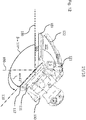
- Fig. 1a shows a perspective view of a first exemplary embodiment of the guiding device 100 according to the invention.
- the guiding device has an impact protection 107 or protector, which is preferably designed to be circumferential and serves to protect the grinding disk 117 and thus the gearing of the tool on the one hand and surfaces or an operator on the other.
- the guide plate 115 or the guide element 101 is attached on the impact protection 107 of the tool 111.
- the interface between the guide member 101 and the bumper 107 can be used as an angle device in this embodiment because the guide plate is pivoted.
- the guide device 100 has a guide element 101 which is mounted rotatably about a rotation axis 106 on the side facing the tool 111 .
- the axis of rotation 106 can be arranged near the plane of action of the sanding disc 117 essentially at the level of the impact protection 107 .
- the tool 111 with the sanding disc 117 is designed for surface machining and can, in particular, machine edges with a regular and precise sanding pattern when the axis of rotation is arranged in this way.
- the tool 111 is connected to the guide device 100 by means of a connecting arrangement 130 in such a way that the tool 111 is arranged vertically to the plane of the guide plates.
- Other arrangements such as a horizontal or angled position of the tool 111 are conceivable as long as the center of gravity of the connected tool prevents the guide device from tipping over as far as possible.
- a handle top 103 is provided for improved handling of the guiding device.
- connection arrangement 130 is used on the one hand to hold the handle 103 and on the other hand to hold the impact protection 107.
- the handle 103 can also be ergonomically adapted to the hand and other handle configurations, not shown, can be implemented.
- the advantageously positive connection with the connection arrangement 130 can be different than in Fig. 1a be designed.
- Fig. 1b the guide plate or the guide element 101 is shown in detail obliquely from below and the axis of rotation for angle adjustment is shown as a dashed line with the reference number 106 .
- the guide element 101 has a guide plate 115 which has an outsole 116 on the lower portion.
- the outsole can, for example, be made of a soft material such as velor or the like.
- the outsole can be changed depending on different surfaces and can be designed not only soft but also hard or wear-resistant.
- Figure 2a shows a perspective view of a further exemplary embodiment of the guiding device 100 according to the invention, diagonally from above, with a tool.
- This embodiment has an alternative handle geometry than in Fig. 1a on.
- the handle 103 or the upper part of the handle is not only connected to the connection arrangement 130, but also to the angle device 102.
- a rail system and a movable angle holder 104 are used here to set desired angles.
- This guide device thus has a virtual pivot point or axis of rotation .
- Figure 2b shows a front view of the guiding device of FIG Figure 2a .
- the grinding disk 117 can be seen in particular from the tool 111 .
- the section AA indicated, which is along the central axis of the Handle 103 and the central axis of the guide element 101 and the guide plate 115 goes.
- FIG. 2c shows the tool 111 with its own handle area 119 and the sanding pad 117.
- the impact protection 107 is located near the sanding pad 117 and is part of the connection assembly 130.
- the connection assembly 130 connects the handle assembly 120 to the tool 111.
- the guide element 101 with the guide plate 115 and sliding sole 116 is connected to the handle assembly 120 by means of the rail system.
- the angle device 102 is designed as a rail system which has displaceable angle brackets 104 and curved guide tracks 105 .
- a predetermined angle can be set in a fixed manner by means of the rotary knob 113 inserted in the upper part of the handle 103 and a counter bearing 137 (completely in Figure 8c shown), which clamps the rail system.
- the selected angle is approx. 90°.
- FIG. 3 shows a perspective view of FIG Figures 2a to 2c shown guide device 100 without a tool.
- This view shows the connector assembly 130 and its components or assemblies, 101, 120 and 130.
- reference numeral 131 designates the upper bracket for the tool (not shown)
- 132 indicates the lower bracket with impact protection 107.
- the retaining brackets 131 and 132 form an oval receptacle 127 with a groove or ribs, in which the tool or the tool neck can be accommodated in a form-fitting manner and on both sides.
- the shape of the receptacle 127 or the shape of one or more grooves and/or form-fitting ribs can vary. In this way, a rigid and secure connection to a tool or a machine can take place.
- the lower retaining bracket 132 can be detached from the upper retaining bracket 131.
- the central axis of the pivot bearing 133 forms the pivot axis about the handle assembly 120 of the guiding device in flexible mode of operation is pivoted.
- the pivot axis is preferably close to or in the axis of intersection of the center plane of the workpiece to be machined and the vertically arranged Z-plane through the center of gravity of the guide device.
- the angular play for the flexible operating mode can be selectively allowed or not allowed by the clamping element 121 depending on the position.
- the angle device 102 can be adjusted to a predeterminable angle with the turning knob 113 .
- the first subassembly of the guide element 101 has the insertable guide plate 115 and sliding elements on the underside. On the underside of this guide plate 115 either rolling elements or elastic elements can be attached. Furthermore, the guide plate 115 can have a receptacle on the underside for detachable and attachable elements, which are selected from the group comprising: sliding sole 116, sliding structure, sliding fabric, sliding fabric and a combination of the elements mentioned.
- the rail system for the angle device 102 is arranged centrally on the upper side of the guide element 101 and on the side facing the connection arrangement.
- This rail system has the slidable angle bracket 104 and the arcuate guideways 105 .
- the guide tracks 105 can engage in the second assembly 120, ie in particular in the rails 112 of the angle device 102.
- Above the rail system of the angle device 102 is the handle area with an upper handle part 103 and a lower handle part 123.
- the handle assembly 120 can be operated with the rotary knob 113 and a counter-element guided in the rail system (see reference number 137 in Figure 8c ) be determined.
- the handle assembly 120 has a holding device 125 at its lower end, which is configured to accommodate the pivot bearing 133 in the receptacle 126.
- the holding device 125 of the handle assembly 120 can be connected to the connecting arrangement 130 with the aid of the pivot bearing 133 and 134.
- the tensioning element 121 By means of the tensioning element 121, the handle assembly 120 can be pivoted in relation to the connection arrangement 130 in flexible operating mode.
- the third assembly of the connector assembly 130 includes the upper and lower brackets 131, 132 as previously described.
- the upper bracket has a receptacle 135 for the pivot bearing 133 .
- a receptacle (not shown) for a further pivot bearing 134 is also provided on the opposite side.
- a holding element 141 in the form of a pin is provided on the rear edge of the upper holding bracket 131 .
- This pin 141 can accommodate the damping element 124 .
- This damping element 124 serves as a stop in order to dampen an end position of the angular play in the flexible operating mode of the guide device 100 .
- the holding bracket 131 has a receptacle 142 for the tensioning element 121 on the upper side.
- Figures 5a and 5b only show the third subassembly or the connection arrangement 130 in the unassembled state with a tool 111.
- the upper holding bracket 131 has a slot 138 on the upper side.
- an angular play around the pivot axis 108 is made possible.
- an angular play is made possible by means of a corresponding position of an eccentric lever, for example in the Figure 11a . illustrated.
- Figure 5a also shows the recording 136 for the in 4 pivot bearing 135 shown.
- the lower bracket 132 can be connected to the upper bracket 131 by means of the connecting elements 139 after the tool has been inserted.
- These connecting elements 139 can be screw connections, for example, and ensure a secure hold in the event of vibrations that occur during operation.
- FIG. 6 shows a perspective view of a further exemplary embodiment of an upper holding bracket 131 of a connection arrangement 130.
- both receptacles 135, 136 for the pivot bearings 134 and 133 can be seen.
- a holding element 141 or pin for receiving a damping element or stop 124 can also be seen.
- the elongated hole 138 is also shown here, which enables or limits the pivotability in the flexible operating mode.
- the axis of rotation or pivot axis 108 of the attachable tool is represented by the dashed line 108; which runs centrally through the receptacles 135, 136.
- FIG. 7 shows a perspective view of a further exemplary embodiment of the guide device with a guide plate 115 in the released state.
- This dissolved state is suitable for changing the abrasive.
- the guide plate 115 can be displaced from the upper part of the guide element 101 away from the tool. In this way, the tool 111 with its handle or the abrasive 117 does not have to be removed from the connection arrangement 130 and time can be saved when changing the abrasive.
- a further advantage of the displaceability of the guide plate is that the angle device does not have to be loosened to change the abrasive, but the set position of the handle assembly 120 in relation to the angle holder can remain the same. In other words, after changing the abrasive, the previous angular position can continue to be used and the surface or the edge can thus be machined precisely.
- the one in the 7 The embodiment shown shows a clamping element 121, which has a different geometry than, for example, that in 4 example shown.
- a mechanical operating element can be selected from the group consisting of a screw connection, a clamping lever, an eccentric clamp or a latching mechanism as the clamping system for fixing and releasing the predeterminable angle.
- Figure 8a Figure 12 shows a front view of the guide device with the guide plate released.
- the grinding disk 117 in particular can be seen from the tool 111 in the lower section.
- section BB which is along the central axis of handle assembly 120 and the central axis of guide member 101 and guide plate 115, is indicated.
- Figure 8b shows the in Figure 8a shown cut BB.
- the position of the guide plate 115 shown is the released position of the guide plate 115.
- a sliding movement can be carried out in the direction of the arrow 145 to release the guide plate 115 to be executed.
- the removal of the abrasive is indicated here by the arrow 147.
- connection arrangement 130 is shaped in such a way that the positive connection between the machine and the connection arrangement 130 has a high degree of rigidity.
- the wall thicknesses of the components should not be greater than 4 mm, for example, so that these components can be produced without any problems using an injection molding process. At the same time, the wall thicknesses are selected in such a way that the rigidity of the end product is guaranteed.
- the drawing shown is not to scale and other wall thicknesses are also conceivable as long as they meet the necessary rigidity requirements. It is advantageous if the material of the guiding device is selected in such a way that the flexible angle setting, and thus the softness, is not dependent on the material.
- FIG. 8b illustrated embodiment shows that a change of abrasive without adjusting the angle device 102 is possible.
- the fixed angle setting can be easily adjusted using the rotary knob 113. It can be adjusted manually by rotating it using a tensioning mechanism.
- This tensioning mechanism between the upper part of the handle and the rail system of the angle device 102 can be provided by different variants.
- an eccentric lever 212 is provided as a clamping mechanism for the different operating modes.
- Figure 8c shows the clamping mechanism of the rail system, ie the rotary knob 113 of FIG Figure 8b in a perspective detail view.
- the rotary knob 113 can be connected to a threaded rod 128 and to a counter-element 137.
- the counter-element 137 acts as a clamping element or pressure disk and can generate the required tension via the rotary movement of the rotary knob 113.
- the pressure disk or the counter-element 137 is pressed against an arc-shaped guideway of the rail system for the purpose of tensioning.
- the angle bracket 104 can be firmly connected to the handle assembly 120 .
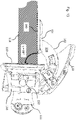
- FIG. 9 shows a side view of the guide device with tool 111 and guide plate 115. 9 shows the released state for changing the abrasive. The abrasive 117 has enough space to be replaced.
- Figures 10a and 10b are details of in 9 shown guiding device shown without the tool 111.
- Figure 10a shows the guide device 9 in the assembled state, ie the guide plate 115 is now arranged much closer to the impact protection 107 than in the previously in the 9 shown released position.
- Figure 10a shows an eccentric lever 121, which is in the cocked position and thus produces a stiff operating condition.
- Figure 10a indicates the section EE, which is in Figure 10b will be shown.
- Figure 10b is the section EE, which was placed through the clamping screw 143.
- the tensioning screw 143 can optionally have an elastic spring element, such as a spring 148.
- the system can be tensioned with the tensioning screw 143 and the spring element 148 shown, ie the rail system 120 can be firmly connected to the connection arrangement 130.
- the eccentric lever 121 is in Figure 10b position shown is used to locate the handle assembly relative to the linkage assembly. A tension of the eccentric lever 121 follows against the counter-element 144. In the position shown Figure 10b of the eccentric lever 121, the clamping surface of the eccentric lever 121 rests against the counter surface of the counter element 144, so that the guide device is in the rigid operating state.
- the pairing of forces occurring in the clamped state between the counter-element 144 and the clamping element 121 is shown here schematically with an arrow.
- Figure 10c shows the section CC, which in Figure 10a shown guide device in the rigid operating state.
- connection arrangement 130 with the upper retaining bracket 131 and the lower retaining bracket 132 and impact protection 107.
- the retaining brackets 131, 132 are held together with the connecting element 139.
- This can be a screw, for example, as in the example shown.
- the section CC shows the axis of rotation 108 of the tool, the axis of rotation of the tool being marked here with a chain line.
- This axis runs centrally through the pivot bearings 133 and 134, which are received by the respective receptacles (135, 136).
- rotation about the axis of rotation is blocked in the rigid operating state.
- the retainer 125 is non-pivotable with respect to the assembly of the linkage assembly 130 .
- Figure 11a the flexible operating state.
- Figure 11a shows a guide device in the flexible operating state without a tool.
- the guide plate 115 can react flexibly in relation to the plane of action of a tool (not shown here) during surface treatment. Flexibility becomes in Figure 11a shown schematically with the dashed lines drawn in bold, which intersect in the axis of rotation 108 .
- the eccentric lever 121 In the flexible operating state, the eccentric lever 121 is folded in the direction of the guide plate in the variant shown here. In this position, the assembly of the handle 120 as well as the guide element 101 can be pivoted in relation to the connection arrangement 130 .
- the ability to pivot about the axis of rotation 108 is +1.5° towards the central axis 146 or ⁇ 1.5 degrees away from the central axis (see arrows).
- the eccentric lever 121 allows a movement or a game to the degrees mentioned.
- larger angular ranges such as +/-10° can also be set up with a correspondingly greater distance between the counter-element 144 and the respective counter-surfaces 151 of the eccentric lever 121 .
- This distance or game 149 is detailed in the sectional view DD or in the Figure 11b shown.
- Figure 11b shows section DD, where the eccentric lever 121' has been moved towards the guide plate.
- a flexible operating state is realized in this eccentric lever position 121'.
- play 149 is permitted between the counter-surface 151 of the eccentric lever 121' and the counter-element 144, and the flexible operating state is thus achieved.
- the guide plate 115 and the assembly of the handle 120 connected therein can be pivoted about the axis of rotation 108 as a result of the play.
- the pivoting is realized about the pivot bearings 133 and 134.
- the guide plate 115 has a running or sliding zone, which can be made of velor, for example. In this way, sensitive surfaces can be protected.
- Figure 12 shows a guiding device in the rigid operating state, where the eccentric lever 21 is positioned in the corresponding seat in the grip area 103.
- the rigid operating state it is particularly important to reliably adhere to the specified angles.
- an angle ⁇ of 133° between the edge surface to be machined and the guide plane 180 is desired.
- the active plane or processing plane of the grinding disk 117 of the tool 111 is marked here with a chain line 110 . If an edge is machined with this angular position, an angle ⁇ of 43° can be produced in relation to the vertical with the reference number 190 .
- angle bracket 104 is no longer visible because the rail assembly has been telescoped so that it is covered by the exterior of the rail assembly (see reference numeral 102) of the handle assembly 120.
- FIG. 12 shows another embodiment in the rigid operating state, where a different angle setting has been selected and a workpiece 118 to be machined is shown.
- the angle holder 104 is visible because a smaller angle is set.
- the desired angle ⁇ is 88° and is marked with the arrow.
- the workpiece 118 is only partially shown and is preferably a panel, which can be made of various materials such as wood and optionally already has a coat of paint.
- the processing plane is marked with the chain line and shows the effective plane 110 of the tool 111, in which the grinding wheel acts on the workpiece 118.
- the tool 111 In order to collect abrasions occurring during processing, the tool 111 generally advantageously has an extraction system.
- the tool 111 shown shows, for example, a connection 150 for abrasion collection containers, in order to to enable dust-free processing during grinding. This is particularly advantageous for fine sanding work.
- the first method step 401 is the provision of a guide device for a tool with at least one guide element and an angle device, which is connected to a tool 111.
- a further method step is the setting 402 of a predetermined angle between the plane of the at least one guide element and an effective plane of the tool by means of the angle device.
- the method includes placing the at least one guide element of the guide device on a workpiece to be machined with at least one edge.
- two handles are provided above the workpiece.
- the handle on the guide element can be used to prevent the tool 111 with suction system from tipping over after it has been placed in place.
- the operator can choose between two different operating states.
- method step 404 he can set the flexible operating state (404) in which the effective plane of the tool can be moved relative to the machining plane for flexible adaptation to the edge surface to be machined.
- the operator can set a rigid operating state in method step 405.
- a predetermined angle is fixed between the plane of at least one guide element and an effective plane of the connected tool. In this way, precise work can be carried out. If the abrasive has been used up, a further method step 406 can be carried out, in which the guide plate is displaced in such a way that easy access to the abrasive is provided and it is therefore easy to change the abrasive.
- the flexible operating state In contrast to the rigid operating state, where there is a rigid connection between the levels mentioned, flexible adaptation to the geometry of the tool is possible in the flexible operating state.
- This working method is particularly suitable for intermediate lacquer sanding.
- the intermediate paint sanding is the sanding that is carried out after the first painting.
- a very regular grinding pattern and a precisely smoothed surface and a low grinding tolerance can advantageously be provided by means of the guiding device according to the invention.
- a damping element can advantageously be provided, which dampens the movement of the operator at the maximum downward deflection.
- Relatively small angular play of +/-1.5° can be set with the present guide device and thus unintentional damage to the surface can be avoided. Very good quality smoothed surfaces can be achieved.
- the invention and the guide device are designed to retrofit tools with a guide device.
- 15 shows schematically the method steps of the retrofitting method 500.
- the retrofitting method 500 firstly provides in method step 501 a guide device.
- Method step 502 includes connecting the tool to the guiding device.
- the guide device comprises a connection arrangement which has a suitable receptacle in order to connect the tool to be retrofitted, preferably in a form-fitting manner. A secure hold can optionally be guaranteed by screw connections.
- the connected tool can be guided either in the rigid operating state (504) or in the more flexible operating state (503).
Landscapes
- Engineering & Computer Science (AREA)
- Mechanical Engineering (AREA)
- Finish Polishing, Edge Sharpening, And Grinding By Specific Grinding Devices (AREA)
Description
- Die Erfindung betrifft eine Führungsvorrichtung, ein System umfassend eine Führungsvorrichtung und ein Werkzeug zur Oberflächenbearbeitung, ein Verfahren zur Oberflächenbearbeitung mit der Führungsvorrichtung und ein Verfahren zur Nachrüstung eines Werkzeuges mit der Führungsvorrichtung.
- Für die Oberflächenbearbeitung sind der Einsatz von automatischen Maschinen Stand der Technik. Bei der Oberflächenbearbeitung sind beispielsweise Schleifelektrowerkzeuge wie der Bandschleifer oder Exzenterschleifer verbreitet.
WO 2006/053138 A2 , welche die Basis für den Oberbegriff des Anspruchs 1 bildet, beschreibt ein Anfaswerkzeug für Marmor, Granit und Ähnliches, das auf eine Schleifmaschine montierbar ist.DE 7905963 U1 betrifft ein bekanntes Kantenfräsgerät mit Handführung zum Anfasen.DE 10 2004 040 900 A1 betrifft eine weitere bekannte Handschleifvorrichtung. - Bei Oberflächenbearbeitung von Kanten mit handgeführten Exzenterschleifer oder ähnlichen Maschinen besteht allerdings das Problem, das das Schleifwerkzeug leicht abkippt und dadurch unerwünschte Schleifschäden wie einen Durchschliff erzeugen kann. In solchen Fällen wird häufig auf das altbewährte Handschleifen zurückgegriffen. Andererseits können zum Vermeiden des Verkantens eines Elektrowerkzeuges wie z.B. eines Schleifers Werkzeugstützelemente wie in der
DE 20 2018 000 381 U1 verwendet werden.DE 3447379 betrifft eine bekannte Vorrichtung zum Führen einer handgeführten Winkelschleifmaschine mit einer Schiene mit längs verlaufenden Hohlwinkelprofil zur Aufnahme der zu bearbeitenden Kante. - Eine manuelle Bearbeitung mit einem Schleifblock ist zum Beispiel bei komplexen Bearbeitungsprozessen wie den Lackzwischenschliff von Kanten von Vorteil. Der Lackzwischenschliff ist der Schliff, der nach dem ersten Lackieren durchgeführt wird. Hierdurch soll eine geglättete Oberfläche entstehen. Durch ein möglichst gleichmäßiges Schleifbild und geringe Schleiftoleranz sollen zudem die Lackauftragsmengen verringert werden und der Poliervorgang verkürzt werden. Die Oberfläche darf dabei nicht beschädigt werden. Eine manuelle Bearbeitung für den Lackzwischenschliff ist als kostengünstige Alternative im Vergleich zu einer Bearbeitung an stationären Maschinen bekannt. Allerdings hat die händische Oberflächenbearbeitung mit dem Handschleifklotz den Nachteil, dass sie mit einem hohen Zeitaufwand verbunden ist und unregelmäßigere bzw. nicht reproduzierbare Schleifbilder als mit einer automatischen Schleifmaschine erzeugt.
- Eine schnelle und genaue Bearbeitung von Kanten ist in einem stationären Bearbeitungszentrum möglich. Hier ist jedoch das Problem gegeben, dass sich Schleifpartikel ablagern können, so dass ein Bearbeitungszentrum eher für einen Grobschliff als für Feinschliffarbeiten geeignet ist. Ferner besteht der Nachteil hoher Investitionskosten. Die bekannten Führungsvorrichtungen von Bearbeitungszentren benötigen im Vergleich zu mobilen Schleifmaschinen einen großen Bauraum und eignen sich insbesondere für die Bearbeitung von relativ kleinen Platten. Bei großen Platten besteht jedoch das Problem, dass die Auflagefläche der stationären Maschine nicht ausreicht. Daher ist es notwendig, dass eine Person die Platte manuell führt oder Rollenböcke das Vorbeiführen der zu bearbeitende Platte an der stationären Schleifmaschine unterstützen. Während die Handführung den Nachteil hat, dass sie zu ungenauen Ergebnissen der Kanten des Werkstückes führt, besteht das Problem, dass Rollenböcke nur bei ebenen Untergrund eingesetzt werden können.
- Daher besteht der Bedarf eine mobile, kompakt gebaute und zugleich genau arbeitende Führungsvorrichtung für Schleif- und Polierwerkzeuge insbesondere zum Kantenschleifen und für komplexe Arbeiten wie den Zwischenschliff beim Lackieren bereitzustellen. Dabei sollen die Vorteile der händischen Führung mit den Vorteilen einer stationären Bearbeitung verbunden werden.
- Ferner sollte die Führungsvorrichtung folgende Anforderungen erfüllen:
Die Führungsvorrichtung soll eine hohe Präzision bei der Oberflächenbearbeitung gewährleisten und in Abhängigkeit der zu bearbeitenden Oberfläche optimal einstellbar sein. Insbesondere ist es wünschenswert, dass die Führungsvorrichtung für einen Lackzwischenschliff keine starre Verbindung aufweist. Zur Erzeugung von präzisen Geometrien ist allerdings eine starre Verbindung nötig, sodass eine Führungsvorrichtung sowohl einen starren als auch einen nicht starren Betriebsmodus beherrschen sollte. Gleichzeitig sollte die Führungsvorrichtung einfach zu bedienen sein. - Die Verbindung des Werkzeuges mit der Führungsvorrichtung soll lösbar sein, wobei die Verbindungsanordnung auch so adaptierbar sein sollte, dass verschiedene Werkzeuge mit der Führungsvorrichtung verbunden werden können. Im Betrieb sollte die Sichtbarkeit des Arbeitsbereiches möglichst wenig eingeschränkt sein. Der Bauraum der Führungsvorrichtung sollte möglichst klein sein, wobei gleichzeitig eine Demontagemöglichkeit des Werkzeuges gegeben sein soll. Die Führungsvorrichtung sollte so konzipiert sein, dass ein Schleifmittelwechsel möglich ist, wenn das Werkzeug mit der Führungsvorrichtung verbunden ist.
- Auf Grundlage der Erfindung sollen die oben genannten Aufgaben besser als bei herkömmlichen Werkzeugen zur Oberflächenbearbeitung gelöst werden, die ausschließlich einen steifen Betriebszustand zur Verfügung stellen.
- Die oben genannten Aufgaben werden durch eine erfindungsgemäße Führungsvorrichtung, System und Verfahren gemäß den Merkmalen der unabhängigen Ansprüche gelöst. Bevorzugte und vorteilhafte Ausgestaltungen der Erfindung ergeben sich aus den sich an den unabhängigen Ansprüchen anschließenden Unteransprüchen und werden nachfolgend näher beschrieben.
- Nach dem Grundgedanken der Erfindung sollen wenigstens zwei Betriebszustände zur Verfügung gestellt werden, wobei das Werkzeug im jeweiligen Betriebszustand bzw. Bearbeitungsmodus sicher festgestellt bzw. eingestellt werden kann.
- Gemäß einem ersten Aspekt der Erfindung wird eine Führungsvorrichtung für ein Werkzeug zur Oberflächenbearbeitung eines Werkstückes umfassend wenigstens ein Führungselement, eine Winkelvorrichtung und eine Verbindungsanordnung zum Verbinden der Führungsvorrichtung mit dem Werkzeug bereitgestellt, wobei mittels der Winkelvorrichtung ein vorbestimmter Winkel zwischen einer Ebene oder Gleitebene des wenigstens einen Führungselementes und einer Wirkebene des verbindbaren Werkzeuges einstellbar ist; und wobei die Vorrichtung zwischen wenigstens einem flexiblen Betriebszustand und einem steifen Betriebszustand umstellbar ist.
- Auf diese Weise kann die Härte, Elastizität oder Steifigkeit der Führungsvorrichtung verändert werden. Wird beispielsweise der flexible Betriebszustand gewählt, kann die gewünschte Flexibilität für einen Lackzwischenschliff bereitgestellt werden. Mit Hilfe der Winkelvorrichtung kann eine sichere Führung des Werkzeuges gewährleistet werden und damit ein Verkanten oder ein Abkippen, die naturgemäß beim Hantieren eines Werkzeuges an zu bearbeitenden Oberflächen ohne eine Winkelvorrichtung auftreten können, vermieden werden.
- Unter dem Begriff "steifer Betriebszustand" soll insbesondere verstanden werden, dass auch bei Krafteinwirkung durch eine das Werkzeug bedienende Person in Richtung der Wirkebene und damit in der Regel in Richtung des zu bearbeitenden Werkstückes bzw. der Schleiffläche der vorbestimmte Winkel fixiert ist. Der flexible Betriebszustand gewährleistet dagegen eine begrenzte Bewegbarkeit der Wirkebene relativ zur Ebene des wenigstens einen Führungselementes d.h. einer Gleitebene, Führungsebene oder Abstützebene.
- Unter dem Begriff "Werkzeug zur Oberflächenbearbeitung" soll insbesondere ein Werkzeug wie ein Schleif- oder Poliergerät verstanden werden, das insbesondere zum Schleifen, Lackzwischenschliff, Polieren oder dergleichen, vorgesehen ist.
- Gemäß einem weiteren Aspekt der Erfindung weist die Führungsvorrichtung für ein Werkzeug zur Oberflächenbearbeitung eines Werkstückes ferner ein Versteifungselement auf, das ausgelegt ist, den steifen Betriebszustand einzustellen.
- Mit Hilfe des Versteifungselementes kann präzise ein vorbestimmter Winkel eingestellt werden. Das Versteifungselement kann bei Bedarf an der Führungsvorrichtung so befestigt oder positioniert werden, dass eine steife, hoch belastbare Führungsvorrichtung bereitsteht. Auf diese Weise kann auch bei hohen Anpressdruck gegen die zu bearbeitende Fläche bzw. Kante eine genaue Werkzeugführung mit dem durch die Winkelvorrichtung vorbestimmten Winkel erfolgen.
- Gemäß einem weiteren Aspekt der Erfindung weist die Verbindungsanordnung eine Ausnehmung für das Versteifungselement auf; wobei das Versteifungselement einen drehbaren Exzenterkörper aufweist, der mit einem Ende eines durch die Winkelvorrichtung verlaufenden Verbindungselementes koppelbar ist und ausgelegt ist, in die Ausnehmung der Verbindungsanordnung wahlweise mit Spiel oder ohne Spiel einzugreifen, um den flexiblen Betriebszustand oder den steifen Betriebszustand einzustellen.
- Auf diese Weise kann selektiv zwischen dem steifen und dem flexiblen Betriebszustand gewählt werden und damit ein optimales Verhalten des Werkzeuges bei der Oberflächenbearbeitung in Abhängigkeit vom Bearbeitungsprozess gewährleistet werden. Das Umstellen von steif bzw. hart zu weich und vice versa kann mit einem Exzenterkörper schnell manuell beispielsweise mit einem geeigneten Betätigungselement wie mit einem Hebel erfolgen.
- Gemäß einem weiteren Aspekt der Erfindung weist die Führungsvorrichtung ferner wenigstens ein elastisches Element zur Einstellung des flexiblen Betriebszustandes auf, wobei das Element ausgewählt ist aus einer Gruppe umfassend:
eine Feder, Dämpfungsplatte, Bolzen mit wenigstens einem elastischen Abschnitt oder eine Kombination der genannten elastischen Elemente. - Auf diese Weise kann vorteilhafterweise eine besonders schonende und genaue Feinstbearbeitung von Oberflächen gewährleistet werden. Diese vorbestimmte Flexibilität kann vorteilhaft für Arbeitsschritte wie den Lackzwischenschliff genutzt werden, die eine besonders feinfühlige und genaue Führung des Schleifgerätes erfordern.
- Gemäß einem weiteren Aspekt der Erfindung weist die Winkelvorrichtung ein Spannsystem zum Feststellen und Lösen eines Winkels auf, umfassend ein mechanisches Bedienelement ausgewählt aus der Gruppe umfassend: eine Schraubverbindung, einen Spannhebel, einen Drehknopf oder einen Einrastmechanismus.
- Auf diese Weise können Anwender einen großen Winkelberiech fest einstellen, wobei der Winkelbereich vorzugsweise zwischen 43°und 92° liegt.
- Gemäß einem weiteren Aspekt der Erfindung weist die Führungsvorrichtung nach einem der vorhergehenden Aspekte ferner wenigstens einen Griff auf, der an der Winkelvorrichtung oder der Verbindungsanordnung oder einem Übergangsbereich zwischen Winkelvorrichtung und Verbindungsanordnung und/oder an dem Führungselement auf der der Führungsebene entgegengesetzten Seite angeordnet ist.
- Der Griff kann als bequem zu umgreifenden Abschnitt ausgebildet sein und optional ergonomische Ausformungen aufweisen, um die Handhabung zu verbessern. Neben einem Handgriff an der Verbindungsanordnung, kann zur besseren Führung ein zweiter Handgriff auf der werkzeugfernen Seite des Führungselements angeordnet sein.
- Gemäß einem weiteren Aspekt der Erfindung weist der Griff wenigstens ein längs verschiebbares Verlängerungselement auf, das mit einem Gegenelement der Verbindungsanordnung oder der Winkelvorrichtung in Eingriff bringbar ist.
- Auf diese Weise kann der Griffbereich in Abhängigkeit von der Bedienperson angepasst und verlängert werden.
- Gemäß einem weiteren Aspekt der Erfindung umfasst die Winkelvorrichtung ein Schienensystem.
- Durch den Einsatz eines Schienensystems können die gewünschten Winkel einfach verstellt werden. Ein Vorteil der Anwendung eines Schienensystems ist, dass der Arbeitsbereich gut einsehbar ist.
- Gemäß einem weiteren Aspekt der Erfindung ist ein auf wenigstens einer bogenförmigen Schiene um einen bestimmten Winkel verschiebbares Element als Griff mit einem Spannsystem ausgebildet.
- Auf dem Schienensystem können vorteilhafterweise Markierungen der einzustellenden Winkel angebracht sein. Mittels des Spannsystems kann ein vorbestimmter bzw. gewünschter Winkel festgestellt bzw. arretiert werden.
- Gemäß einem weiteren Aspekt der Erfindung ist die Spannrichtung des Spannsystems orthogonal zur Gleitbahn der Schiene angeordnet und in der arretierten Stellung der Winkelvorrichtung sind eine erste Kontaktfläche im Griff und eine zweite Kontaktfläche im Schienensystem reibschlüssig festlegbar.
- Auf diese Weise kann ein Spannelement des Spannsystems gegen eine Bahn des Schienensystems gespannt werden, um eine stabile Kraftpaarung zu ergeben.
- Gemäß einem weiteren Aspekt der Erfindung weist das Führungselement wenigstens eine Führungsplatte mit wenigstens einem Rollelement und/oder mit wenigstens einem elastischen Element auf.
- Gemäß einem weiteren Aspekt der Erfindung ist die Führungsplatte an der werkzeugzugewandten Seite um eine Drehachse drehbar gelagert.
- Gemäß einem weiteren Aspekt der Erfindung weist das Führungselement wenigstens eine Aufnahme für eine lösbar befestigbare Gleitplatte, Gleitstruktur, Gleitgewebe und/oder Gleitgewirk mit einer vorbestimmten Gleiteigenschaft in Abhängigkeit einer Werkstücksoberfläche auf.
- Gemäß einem weiteren Aspekt der Erfindung ist eine erste Drehachse der Winkelvorrichtung an der oberen Kante des zu bearbeitenden Werkstückes angeordnet.
- Gemäß einem weiteren Aspekt der Erfindung weist die Führungsvorrichtung im flexiblen Betriebsmodus ein Winkelspiel von +/- 10%, vorzugsweise +/- 2% des mit der Winkelvorrichtung einstellbaren Winkels auf.
- Gemäß einem weiteren Aspekt der Erfindung weist die Führungsvorrichtung ferner einen Anschlag auf, der vorzugsweise zwischen der Winkelvorrichtung und der Verbindungsanordnung angeordnet ist, um im flexiblen Betriebsmodus eine Endlage des Winkelspiels zu dämpfen.
- Auf diese Weise kann im flexiblen Betriebszustand im Bereich der Endlage der Schwenkbewegung der Winkelvorrichtung in Bezug auf die Verbindungsanordnung der Anschlag gedämpft werden. Dabei ist der Anschlag vorzugsweise als ein elastisch verformbares Dämpfungselement ausgebildet, um die maximale Schwenkbewegung der Winkelvorrichtung weich zu dämpfen und damit einen harten Anschlag zu vermeiden. Das Dämpfungselement kann ausgewählt sein aus einer Gruppe umfassend: thermoplastisches Polyurethan, Elastomer, Feder oder andere dämpfende oder flexible Werkstoffe.
- Gemäß einem weiteren Aspekt der Erfindung wird ein System bereitgestellt, umfassend eine Führungsvorrichtung für ein Werkzeug nach einem der vorhergehenden Aspekte und ein Werkzeug zur Oberflächenbearbeitung.
- Gemäß einem weiteren Aspekt des erfindungsgemäßen Systems ist das Werkzeug ein handgeführtes oder wenigstens teilweise automatisch geführtes Schleifelektrowerkzeug.
- Dabei kann das Schleifelektrowerkzeug beispielsweise ein Schwing- oder Deltaschleifer oder ein Exzenterschleifer oder ein oszillierendes Multitool sein.
- Gemäß einem weiteren Aspekt des erfindungsgemäßen Systems ist wenigstens ein Teil des Führungselementes zum Schleifmittelwechsel in eine Position von der Wirkebene weg verschiebbar.
- Auf diese Weise muss nicht das komplette System auseinandergebaut werden, um Schleifmittel bzw. Schleifpapier wechseln zu können. Damit wird das Problem gelöst, dass ansonsten das Schleifpapier durch einen engen Spalt zwischen Maschine und Führungselement bzw. Führungsplatte geführt werden muss.
- Gemäß einem weiteren Aspekt der Erfindung wird ein Verfahren zur Oberflächenbearbeitung von Kantenflächen an Werkstücken bereitgestellt, wobei das Verfahren die folgenden Schritte umfasst:
Bereitstellen einer Führungsvorrichtung eines Werkzeuges mit wenigstens einem Führungselement und einer Winkelvorrichtung, welche mit einem Werkzeug verbunden ist; Einstellen eines vorbestimmten Winkels zwischen der Ebene des wenigstens einen Führungselementes und einer Wirkebene des Werkzeuges mittels der Winkelvorrichtung; Auflegen des wenigstens einen Führungselementes der Führungsvorrichtung auf ein zu bearbeitendes Werkstück mit wenigstens einer Kante; Wahlweise Einstellen eines ersten flexiblen Betriebszustandes, in dem die Wirkebene des Werkzeuges relativ zur Bearbeitungsebene zur flexiblen Anpassung an die zu bearbeitende Kantenoberfläche bewegbar ist oder Einstellen eines zweiten steifen Betriebszustandes, in dem ein vorbestimmter Winkel zwischen der Ebene wenigstens eines Führungselementes und einer Wirkebene des verbundenen Werkzeuges fixiert ist. - Gemäß einem weiteren Aspekt der Erfindung wird ein Verfahren zur Nachrüstung eines Werkzeuges mit einer Führungsvorrichtung des Werkzeuges mit wenigstens einem Führungselement; und einer Winkelvorrichtung bereitgestellt, das die folgenden Verfahrensschritte umfasst:
Bereitstellen einer Führungsvorrichtung für ein Werkzeug mit wenigstens dem Führungselement; und der Winkelvorrichtung; und Verbinden des Werkzeuges zur Oberflächenbearbeitung mit der Führungsvorrichtung des Werkzeuges mittels einer Verbindungsanordnung. - Die Anbindung der Maschine kann beispielsweise über den Stoßschutz erfolgen. Eine Schraubverbindung ist nicht zwingend nötig, wenn der Formschluss zwischen Maschine und Stoßschutz bereits eine hohe Steifigkeit aufweist. Zusätzliche Befestigungsmittel wie Schraubverbindungen können jedoch vorteilhafterweise ein durch Vibrationen oder Stöße verursachtes Lösen der Maschine aus dem Stoßschutz verhindern und im Betrieb eine sichere Verbindung des Werkzeuges mit der Verbindungsanordnung gewährleisten.
- Weitere Merkmale und Vorteile der Erfindung ergeben sich anhand der nachfolgenden Zeichnungen in denen vorteilhafte Ausführungsbeispiele einer erfindungsgemäßen Führungsvorrichtung beispielhaft dargestellt werden, ohne die Erfindung auf die gezeigten Ausführungsbeispiele zu beschränken. Die Zeichnungen zeigen:
-
Fig. 1a zeigt eine perspektivische Ansicht eines Ausführungsbeispiels der erfindungsgemäßen Führungsvorrichtung mit einem Führungselement, das an der werkzeugzugewandten Seite um eine Drehachse drehbar gelagert ist; -
Fig. 1b zeigt eine perspektivische Detailansicht des Führungselementes an die Verbindungsanordnung der Führungsvorrichtung; -
Fig. 2a eine perspektivische Ansicht eines weiteren Ausführungsbeispiels der erfindungsgemäßen Führungsvorrichtung von schräg oben mit einem Werkzeug und einer Führungsplatte im zusammenmontierten Zustand bzw. in der Arbeitsposition; -
Fig. 2b eine Vorderansicht der Führungsvorrichtung derFig. 2a ; -
Fig. 2c eine Schnittansicht entlang dem Schnitt A-A derFig. 2a d.h. entlang der Längsachse des Handgriffes der Führungsvorrichtung; -
Fig. 3 eine perspektivische Ansicht der inFig. 2a bis 2c gezeigten Führungsvorrichtung ohne Werkzeug; -
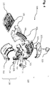
Fig. 4 Explosionsansicht der inFig. 3 gezeigten Führungsvorrichtung ohne Werkzeug; -
Fig. 5a eine seitliche Explosionsansicht der Verbindungsanordnung der Führungsvorrichtung und einem Werkzeug; -
Fig. 5b perspektivische Explosionsansicht der Haltebügel der Verbindungsanordnung und des Werkzeuges derFig. 5a ; -
Fig. 6 eine perspektivische Ansicht eines weiteren Ausführungsbeispiels eines oberen Haltebügels einer Verbindungsanordnung; -
Fig. 7 eine perspektivische Ansicht eines weiteren Ausführungsbeispiels der Führungsvorrichtung mit einer Führungsplatte im gelösten Zustand zum Schleifmittelwechsel; -
Fig. 8a eine Vorderansicht der Führungsvorrichtung derFig. 7 ; -
Fig. 8b eine Schnittansicht entlang dem Schnitt B-B derFig. 8a ; -
Fig. 8c zeigt eine perspektivische Detailansicht des Drehknopfes mit Spannelement; -
Fig. 9 eine Seitenansicht der Führungsvorrichtung mit Werkzeug und mit der Führungsplatte des Führungselementes im gelösten Zustand zum Schleifmittelwechsel; -
Fig. 10a eine Seitenansicht der Führungsvorrichtung ohne Werkzeug; -
Fig. 10b die Schnittansicht entlang dem Schnitt E-E derFig. 10a im steifen bzw. starren Betriebszustand; -
Fig. 10c die Schnittansicht entlang dem Schnitt C-C derFig. 10a ; -
Fig. 11 a eine Führungsvorrichtung im flexiblen Betriebszustand ohne ein Werkzeug; -
Fig. 11b die Schnittansicht entlang dem Schnitt D-D derFig. 11a ; -
Fig. 12 eine Führungsvorrichtung im steifen Betriebszustand mit Werkzeug mit einem festgestellten flachen Winkel; -
Fig. 13 eine Führungsvorrichtung im steifen Betriebszustand mit Werkzeug mit einer weiteren beispielhaften Winkeleinstellung; -
Fig. 14 ein erfindungsgemäßes Verfahren zur Oberflächenbearbeitung von Kantenflächen an Werkstücken; und -
Fig. 15 ein Verfahren zur Nachrüstung eines Werkzeuges. - Die Darstellungen sind schematisch und nicht zwingend maßstabsgerecht. Sie zeigen darüber hinaus nicht alle Details, sondern beschränken sich zum Teil auf die Darstellung der erfindungswesentlichen Einzelheiten sowie weiterer Merkmale, die die Erläuterung und Beschreibung der Erfindung erleichtern. Gleiche Elemente in den unterschiedlichen Figuren werden mit den gleichen Bezugszeichen bezeichnet. In der folgenden Figurenbeschreibung werden verschiedene räumliche Bezeichnungen oder Bezeichnungen in Bezug auf Richtungen angegeben. Es wird darauf hingewiesen, dass Bezeichnungen wie oben unten, vertikal, horizontal oder erste, zweite und dritte zum besseren Verständnis der Figuren verwendet werden, aber die Ausführungsbeispiele nicht auf die angegebenen Bezeichnungen beschränken.
-
Fig. 1a zeigt eine perspektivische Ansicht eines ersten Ausführungsbeispiels der erfindungsgemäßen Führungsvorrichtung 100. Die Führungsvorrichtung weist einen Stoßschutz 107 oder Protektor auf, der bevorzugt umlaufend ausgebildet ist und dazu dient, einerseits den Schleifteller 117 und damit das Getriebe des Werkzeuges und anderseits Oberflächen oder eine Bedienperson zu schützen. An dem Stoßschutz 107 des Werkzeuges 111 ist in der Ausführungsform, die inFig. 1a gezeigt wird, die Führungsplatte 115 bzw. das Führungselement 101 angebunden. Die Schnittstelle zwischen dem Führungselement 101 und dem Stoßschutz 107 kann in dieser Ausführungsform als Winkelvorrichtung verwendet werden, da die Führungsplatte drehbar gelagert ist. In anderen Worten weist die Führungsvorrichtung 100 ein Führungselement 101 auf, das an der dem Werkzeug 111 zugewandten Seite um eine Drehachse 106 drehbar gelagert ist. - Auf diese Weise kann die Drehachse 106 nahe der Wirkebene des Schleiftellers 117 im Wesentlichen auf Höhe des Stoßschutzes 107 angeordnet sein. Das Werkzeug 111 mit dem Schleifteller 117 ist zur Oberflächenbearbeitung ausgelegt und kann bei einer so angeordneten Drehachsenlage insbesondere Kanten mit einem regelmäßigen und genauen Schleifbild bearbeiten.
- Mittels einer Verbindungsanordnung 130 ist das Werkzeug 111 mit der Führungsvorrichtung 100 so verbunden, dass das Werkzeug 111 vertikal zur Ebene der Führungsplatten angeordnet ist. Andere Anordnungen wie eine horizontale oder abgewinkelte Position des Werkzeuges 111 sind denkbar, solange die Schwerpunktlage des angebundenen Werkzeuges ein Abkippen der Führungsvorrichtung so weit wie möglich vermeidet. Für eine verbesserte Handhabung der Führungsvorrichtung wird ein Griffoberteil 103 bereitgestellt.
- In der gezeigten Ausführungsform wird die Verbindungsanordnung 130 zum einen zum Halten des Griffes 103 verwendet und zum anderen zum Halten des Stoßschutzes 107. Der Griff 103 kann auch ergonomisch an die Hand angepasst werden und andere nicht gezeigte Griffausführungen können realisiert werden. In Abhängigkeit von den zu verbindenden Werkzeugen kann die vorteilhafterweise formschlüssige Verbindung mit der Verbindungsanordnung 130 anders als in
Fig. 1a gestaltet sein. - In
Fig. 1b wird die Führungsplatte bzw. das Führungselement 101 im Detail von schräg unten gezeigt und mit dem Bezugszeichen 106 die Drehachse zur Winkeleinstellung als Strichlinie gezeigt. Das Führungselement 101 weist eine Führungsplatte 115 auf, die eine Laufsohle 116 am unteren Abschnitt aufweist. Die Laufsohle kann beispielsweise aus einem weichem Material wie Velours oder Ähnliches sein. Die Laufsohle ist in Abhängigkeit von unterschiedlichen Untergründen wechselbar und kann nicht nur weich sondern auch hart oder verschleißfest ausgebildet sein. -
Fig. 2a zeigt eine perspektivische Ansicht eines weiteren Ausführungsbeispiels der erfindungsgemäßen Führungsvorrichtung 100 von schräg oben mit einem Werkzeug. Diese Ausführungsform weist eine alternative Griffgeometrie als inFig. 1a auf. Der Griff 103 bzw. das Griffoberteil ist nicht nur mit der Verbindungsanordnung 130 verbunden, sondern auch mit der Winkelvorrichtung 102. Zur Einstellung von gewünschten Winkeln wird hier ein Schienensystem verwendet und ein verschiebbarer Winkelhalter 104. Damit weist diese Führungsvorrichtung einen virtuellen Drehpunkt bzw. Drehachse auf. - Der Aufbau des Schienensystems unterteilt sich in die folgende drei Bauteilgruppen:
- Erste Gruppe 101:
Das Führungselement 101, die eine Führungsplatte 110 aufweist. Weiterhin weist das Führungselement 101 eine Aufnahme für die im Griff 103 angeordneten Schienen auf. - Zweite Gruppe 120:
Der Griffbereich 103, der im unteren Teil mit den Aufnahmeschienen des Führungselementes in Eingriff bringbare Schienen und bogenförmige Führungsbahnen 105 aufweist, wie sie beispielsweise in dem Schnitt A-A derFig. 2c gezeigt werden. - Dritte Gruppe 130:
Die Verbindungsanordnung 130 verbindet die Griffbaugruppe (2. Gruppe) mit dem Werkzeug 111. -
Fig. 2b zeigt eine Vorderansicht der Führungsvorrichtung derFig. 2a . In dieser Ansicht ist von dem Werkzeug 111 insbesondere der Schleifteller 117 zu sehen. Ferner wird in derFig. 2b der Schnitt A-A angezeigt, der entlang der Mittelachse des Griffes 103 und der Mittelachse des Führungselementes 101 sowie der Führungsplatte 115 geht. - Dieser Schnitt A-A wird in
Fig. 2c gezeigt.Fig. 2c zeigt das Werkzeug 111 mit einem eigenen Griffbereich 119 sowie den Schleifteller 117. Der Stoßschutz 107 befindet sich nahe des Schleiftellers 117 und ist Teil der Verbindungsanordnung 130. Die Verbindungsanordnung 130 verbindet die Griffbaugruppe 120 mit dem Werkzeug 111. - Das Führungselement 101 mit der Führungsplatte 115 und Gleitsohle 116 wird mittels des Schienensystems mit der Griffbaugruppe 120 verbunden. Die Winkelvorrichtung 102 ist als Schienensystem ausgebildet, welches verschiebbare Winkelhalter 104 und bogenförmige Führungsbahnen 105 ausweist. Ein vorbestimmter Winkel ist fest einstellbar mittels des im Griffoberteil 103 eingeführten Drehknopfs 113 und einem Gegenlager 137 (vollständig in
Fig. 8c gezeigt), welches das Schienensystem verspannt. Im gezeigten Beispiel beträgt der gewählte Winkel ca. 90°. -
Fig. 3 zeigt eine perspektivische Ansicht der inFig. 2a bis 2c gezeigten Führungsvorrichtung 100 ohne ein Werkzeug. Diese Ansicht zeigt die Verbindungsanordnung 130 und deren Bauteile bzw. Bauteilgruppen, 101, 120 und 130. In der Verbindungsanordnung 130 kennzeichnet das Bezugszeichen 131 den oberen Haltebügel für das (nicht gezeigte) Werkzeug, während 132 den unteren Haltebügel mit Stoßschutz 107 anzeigt. Die Haltebügel 131 und 132 bilden in der gezeigten Variante eine ovale Aufnahme 127 mit einer Nut oder Rippen, in denen das Werkzeug bzw. der Werkzeughals formschlüssig und beidseitig aufgenommen werden kann. In Abhängigkeit der Form des aufzunehmenden Werkzeuges kann die Form der Aufnahme 127 bzw. die Form einer oder mehrerer Nuten und/oder formschlüssiger Rippen variieren. Auf diese Weise kann eine steife und sichere Anbindung an ein Werkzeug oder eine Maschine erfolgen. Zur Aufnahme des Werkzeuges (vgl.Fig. 2a , die eine Werkzeuganbindung zeigt) kann der untere Haltebügel 132 von dem oberen Haltebügel 131 gelöst werden. - Die Mittelachse des Schwenklagers 133 bildet die Schwenkachse um die die Griffbaugruppe 120 der Führungsvorrichtung im flexiblen Betriebsmodus schwenkbar gelagert ist. Die Schwenkachse liegt vorzugsweise nahe oder in der Schnittachse der Mittelebene des zu bearbeitenden Werkstückes und der vertikal angeordneten Z-Ebene durch den Schwerpunkt der Führungsvorrichtung. Das Winkelspiel für den flexiblen Betriebsmodus kann durch das Spannelement 121 in Abhängigkeit von der Stellung wahlweise zugelassen werden oder nicht zugelassen werden. Die Winkelvorrichtung 102 kann in einen vorbestimmbaren Winkel mit dem Drehknopf 113 eingestellt werden.
-
Fig. 4 zeigt eine Explosionsansicht der inFig. 3 gezeigten Führungsvorrichtung. Die erste Baugruppe des Führungselementes 101 weist an der Unterseite die einfügbare Führungsplatte 115 und Gleitelemente auf. An der Unterseite dieser Führungsplatte 115 können wahlweise Rollelemente oder elastische Elemente befestigt werden. Ferner kann die Führungsplatte 115 an der Unterseite eine Aufnahme aufweisen für lösbare und befestigbare Elemente, die ausgewählt sind aus der Gruppe umfassend: Gleitsohle 116, Gleitstruktur, Gleitgewebe, Gleitgewirk und eine Kombination der genannten Elemente. - An der Oberseite des Führungselementes 101 ist mittig und auf der der Verbindungsanordnung zugewandten Seite das Schienensystem für die Winkelvorrichtung 102 angeordnet. Dieses Schienensystem weist den verschiebbaren Winkelhalter 104 und die bogenförmigen Führungsbahnen 105 auf. Die Führungsbahnen 105 können in die zweite Baugruppe 120, d.h. insbesondere in die Schienen 112 der Winkelvorrichtung 102 eingreifen. Oberhalb des Schienensystems der Winkelvorrichtung 102 ist der Griffbereich angeordnet mit einem Griffoberteil 103 und einem Griffunterteil 123. Die Griffbaugruppe 120 kann mit dem Drehknopf 113 und einem in dem Schienensystem geführten Gegenelement (siehe Bezugszeichen 137 in
Fig. 8c ) festgelegt werden. - Weiterhin weist die Griffbaugruppe 120 an ihrem unteren Ende eine Haltevorrichtung 125 auf, die konfiguriert ist, das Schwenklager 133 aufzunehmen in der Aufnahme 126. Mit Hilfe des Schwenklagers 133 und 134 ist die Haltevorrichtung 125 der Griffbaugruppe 120 mit der Verbindungsanordnung 130 verbindbar. Mittels dem Spannelement 121 kann eine Verschwenkbarkeit der Griffbaugruppe 120 in Bezug auf die Verbindungsandordnung 130 in flexiblen Betriebsmodus eingestellt werden.
- Die dritte Baugruppe der Verbindungsanordnung 130 weist wie zuvor beschrieben den oberen und unteren Haltebügel 131, 132 auf. Der obere Haltebügel weist eine Aufnahme 135 für das Schwenklager 133 auf. Auf der gegenüberliegenden Seite ist ebenfalls eine Aufnahme (nicht gezeigt) für ein weiteres Schwenklager 134 vorgesehen. Auf der hinteren Kante des oberen Haltebügels 131 ist ein Halteelement 141 in Form eines Pins vorgesehen. Dieser Pin 141 kann das Dämpfungselement 124 aufnehmen. Dieses Dämpfungselement 124 dient als Anschlag, um eine Endlage des Winkelspiels im flexiblen Betriebsmodus der Führungsvorrichtung 100 zu dämpfen. Ferner weist auf der Oberseite der Haltebügel 131 eine Aufnahme 142 für das Spannelement 121 auf.
-
Fig. 5a und Fig. 5b zeigen lediglich die dritte Baugruppe bzw. die Verbindungsanordnung 130 im nicht montierten Zustand mit einem Werkzeug 111. Der obere Haltebügel 131 weist an der oberen Seite ein Langloch 138 auf. Im flexiblen Betriebsmodus wird ein Winkelspiel um die Schwenkachse 108 ermöglicht. Wie ein Winkelspiel mittels einer entsprechenden Stellung eines Exzenterhebels ermöglicht wird, wird z.B. in derFig. 11a . illustriert. -
Fig. 5a zeigt zudem die Aufnahme 136 für das inFig. 4 gezeigte Schwenklager 135. - Der untere Haltebügel 132 kann mit dem oberen Haltebügel 131 nach Einfügen des Werkzeuges mittels der Verbindungselemente 139 verbunden werden. Diese Verbindungselemente 139 können beispielsweise Schraubverbindungen sein und gewähren sicheren Halt bei Vibrationen, wie sie im Betrieb vorkommen.
-
Fig. 6 zeigt eine perspektivische Ansicht eines weiteren Ausführungsbeispiels eines oberen Haltebügels 131 einer Verbindungsanordnung 130. Bei dieser perspektivischen Darstellung können beide Aufnahmen 135, 136 für die nicht gezeigten Schwenklager 134 und 133 gesehen werden. Zudem ist ein Halteelement 141 bzw. Pin zur Aufnahme eines Dämpfungselementes bzw. -anschlages 124 zu sehen. Ferner ist auch hier das Langloch 138 dargestellt, das die Schwenkbarkeit im flexiblen Betriebsmodus ermöglicht bzw. begrenzt. Durch die gestrichelte Linie 108 ist die Drehachse oder Schwenkachse 108 des anschließbaren Werkzeuges dargestellt; die mittig durch die Aufnahmen 135, 136 verläuft. -
Fig. 7 zeigt eine perspektivische Ansicht eines weiteren Ausführungsbeispiels der Führungsvorrichtung mit einer Führungsplatte 115 im gelösten Zustand. Dieser gelöste Zustand ist zum Schleifmittelwechsel geeignet. Mit Hilfe des Betätigungselementes 114 bzw. eines Drückers kann die Führungsplatte 115 von dem oberen Teil des Führungselementes 101 weg von dem Werkzeug verschoben werden. Auf diese Weise muss nicht das Werkzeug 111 mit seinem Griff oder dem Schleifmittel 117 aus der Verbindungsanordnung 130 herausgenommen werden und es kann Zeit beim Schleifmittelwechsel eingespart werden. - Ein weiterer Vorteil der Verschiebbarkeit der Führungsplatte ist, dass nicht die Winkelvorrichtung zum Schleifmittelwechsel gelöst werden muss, sondern die eingestellte Position der Griffbaugruppe 120 in Bezug zu dem Winkelhalter gleichbleiben kann. In anderen Worten, nach einem Schleifmittelwechsel kann die vorherige Winkelposition weiterverwendet werden und eine genaue Bearbeitung der Oberfläche bzw. der Kante kann somit erfolgen.
- Die in der
Fig. 7 gezeigte Ausführungsform zeigt ein Spannelement 121, das eine andere Geometrie als beispielsweise das inFig. 4 gezeigte Beispiel aufweist. Mehrere Varianten der Geometrie für die Spannelemente 121 sowie der Drehknopf 113 sind möglich. An Stelle des Drehknopfes 113 kann als Spannsystem zum Feststellen und Lösen des vorbestimmbaren Winkels beispielsweise ein mechanisches Bedienelement ausgewählt werden aus der Gruppe umfassend eine Schraubverbindung, einen Spannhebel, einen Exzenterspanner oder einen Einrastmechanismus. -
Fig. 8a zeigt eine Vorderansicht der Führungsvorrichtung, wobei die Führungsplatte gelöst ist. In dieser Ansicht ist von dem Werkzeug 111 im unteren Abschnitt insbesondere der Schleifteller 117 zu sehen. Ferner wird in derFig. 8a der Schnitt B-B angezeigt, der entlang der Mittelachse der Griffbaugruppe 120 und der Mittelachse des Führungselementes 101 sowie der Führungsplatte 115 geht. -
Fig. 8b zeigt den inFig. 8a gezeigten Schnitt B-B. Die inFig. 8b gezeigte Stellung der Führungsplatte 115 ist die gelöste Stellung der Führungsplatte 115. Nachdem der Drücker bzw. das Betätigungselement 114 betätigt worden ist, kann in Richtung des Pfeiles 145 eine Verschiebebewegung zum Lösen der Führungsplatte 115 ausgeführt werden. Nach der Verschiebung der Führungsplatte 115 ist ausreichend Platz zwischen dem werkzeugseitigen Ende der Führungsplatte 115 und dem Schleifmittel 117 vorhanden, um das Schleifmittel zu wechseln. Das Abnehmen des Schleifmittels wird hier mit dem Pfeil 147 angedeutet. - Die Verbindungsanordnung 130 ist so geformt, dass der Formschluss zwischen Maschine und Verbindungsanordnung 130 eine hohe Steifigkeit aufweist. Die Wandstärken sollen bei den Bauteilen nicht größer als bspw. 4 mm sein, damit diese Bauteile problemlos durch ein Spritzgussverfahren herstellbar sind. Gleichzeitig sind die Wandstärken so gewählt, dass die Steifigkeit des Endproduktes gewährleistet wird. Die dargestellte Zeichnung ist nicht maßstabsgetreu und es können auch anderen Wandstärken denkbar sein, solange sie die notwendigen Steifigkeitsbedingungen erfüllen. Es ist vorteilhaft, wenn das Material der Führungsvorrichtung so gewählt ist, dass die flexible Winkeleinstellung, und damit die Weichheit, nicht vom Material abhängig ist.
- In dem in
Fig. 8b dargestellten Ausführungsbeispiel wird gezeigt, dass ein Schleifmittelwechsel ohne Verstellung der Winkelvorrichtung 102 möglich ist. Die feste Winkeleinstellung ist mittels des Drehknopfes 113 leicht einstellbar. Sie ist mit Hilfe eines Spannmechanismus manuell durch Drehung einstellbar. Dieser Spannmechanismus zwischen Griffoberteil und Schienensystem der Winkelvorrichtung 102 kann durch verschiedene Varianten bereitgestellt werden. In der inFig. 8a gezeigten Variante ist ein Exzenterhebel 212 als Spannmechanismus für die verschiedenen Betriebsmodi vorgesehen. -
Fig. 8c zeigt den Spannmechanismus des Schienensystems d.h. den Drehknopf 113 derFig. 8b in einer perspektivischen Detailansicht. Der Drehknopf 113 ist mit einer Gewindestange 128 verbindbar sowie mit einem Gegenelement 137. Das Gegenelement 137 fungiert als Spannelement oder Druckscheibe und kann die benötigte Spannung über die Drehbewegung des Drehknopfes 113 erzeugen. Dabei wird zum Spannen die Druckscheibe bzw. das Gegenelement 137 gegen eine bogenförmige Führungsbahn des Schienensystems gepresst. Auf diese Weise kann der Winkelhalter 104 mit der Griffbaugruppe 120 fest verbunden werden. -
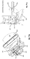
Fig. 9 zeigt eine Seitenansicht der Führungsvorrichtung mit Werkzeug 111 und mit der Führungsplatte 115.Fig. 9 zeigt den gelösten Zustand zum Schleifmittelwechsel. Das Schleifmittel 117 hat genügend Raum um ausgetauscht zu werden. In den folgenden Figuren,Fig. 10a und 10b werden Details der inFig. 9 gezeigten Führungsvorrichtung gezeigt ohne das Werkzeug 111. -
Fig. 10a zeigt die Führungsvorrichtung derFig. 9 im zusammenmontierten Zustand, d.h. die Führungsplatte 115 ist nun wesentlich näher an dem Stoßschutz 107 angeordnet als in der zuvor in derFig. 9 gezeigten gelösten Stellung.Fig. 10a zeigt einen Exzenterhebel 121, der sich in der gespannten Stellung befindet und somit einen steifen Betriebszustand herstellt.Fig. 10a zeigt den Schnitt E-E an, der inFig. 10b gezeigt wird. -
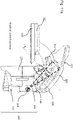
Fig. 10b ist der Schnitt E-E, der durch die Spannschraube 143 gelegt wurde. Die Spannschraube 143 kann optional ein elastisches Federelement aufweisen, wie zum Beispiel eine Feder 148. Mit der Spannschraube 143 und dem gezeigten Federelement 148 kann das System gespannt werden, d.h. das Schienensystem 120 mit der Verbindungsanordnung 130 fest verbunden werden. Der Exzenterhebel 121 wird in der inFig. 10b gezeigten Stellung zur Festlegung der Griffbaugruppe in Bezug zur Verbindungsanordnung verwendet. Eine Spannung des Exzenterhebels 121 folgt gegen das Gegenelement 144. In der gezeigten StellungFig. 10b des Exzenterhebels 121 liegt die Spannfläche des Exzenterhebels 121 an der Gegenfläche des Gegenelementes 144 an, sodass sich die Führungsvorrichtung im steifen Betriebszustand befindet. Die im gespannten Zustand entstehende Kraftpaarung zwischen dem Gegenelement 144 und dem Spannelement 121 wird hier schematisch mit einem Pfeil gezeigt. -
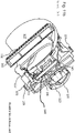
Fig. 10c zeigt den Schnitt C-C, der inFig. 10a gezeigten Führungsvorrichtung im steifen Betriebszustand. In der unteren Hälfte derFig. 10c sieht man die Verbindungsanordnung 130 mit dem oberen Haltebügel 131 und dem unteren Haltebügel 132 und Stoßschutz 107. Die Haltebügel 131, 132 werden mit dem Verbindungselement 139 zusammengehalten. Dies kann beispielsweise eine Schraube wie im gezeigten Beispiel sein. - Der Schnitt C-C zeigt die Drehachse 108 des Werkzeuges, wobei die Drehachse des Werkzeuges hier mit einer Strichpunkt-Linie gekennzeichnet wird. Diese Achse verläuft mittig zentral durch die Schwenklager 133 und 134, die durch die jeweiligen Aufnahmen (135, 136) aufgenommen werden. Eine Drehbarkeit um die Drehachse ist jedoch im steifen Betriebszustand blockiert. In dem steifen Betriebszustand ist die Haltevorrichtung 125 in Bezug auf die Baugruppe der Verbindungsanordnung 130 nicht verschwenkbar. Im Gegensatz dazu zeigt die folgende
Fig. 11a den flexiblen Betriebszustand. -
Fig. 11a zeigt eine Führungsvorrichtung im flexiblen Betriebszustand ohne ein Werkzeug. Im flexiblen Betriebszustand kann die Führungsplatte 115 flexibel in Bezug auf die Wirkebene eines Werkzeuges (hier nicht gezeigt) bei der Oberflächenbearbeitung reagieren. Flexibilität wird inFig. 11a schematisch mit den fett gezeichneten Strichlinien, die sich in der Drehachse 108 schneiden, dargestellt. - In dem flexiblen Betriebszustand ist in der hier gezeigten Variante der Exzenterhebel 121 Richtung Führungsplatte geklappt. In dieser Stellung kann die Baugruppe des Griffes 120 sowie das Führungselement 101 in Bezug zu der Verbindungsanordnung 130 verschwenkt werden. Die Verschwenkbarkeit um die Drehachse 108 ist jeweils +1,5° zur Mittelachse 146 hin bzw. -1,5 Grad von der Mittelachse weg (siehe Pfeile). Der Exzenterhebel 121 lässt eine Bewegung bzw. ein Spiel um die genannten Gradzahlen zu. Alternativ sind auch größere Winkelbereiche wie +/- 10° bei entsprechend größeren Abstand des Gegenelementes 144 zu den jeweiligen Gegenflächen 151 des Exzenterhebels 121 einrichtbar. Dieser Abstand bzw. Spiel 149 wird im Detail in der Schnittdarstellung D-D bzw. in der
Fig. 11b gezeigt. -
Fig. 11b zeigt den Schnitt D-D, wo der Exzenterhebel 121' in Richtung Führungsplatte bewegt wurde. In dem gezeigten Beispiel ist bei dieser Exzenterhebelstellung 121' ein flexibler Betriebszustand realisiert. In dem vorliegenden Ausführungsbeispiel besteht in dieser Stellung des Exzenterhebels 121' kein Kontakt zu den Gegenelementen 144. In anderen Worten wird ein Spiel 149 zwischen der Gegenfläche 151 des Exzenterhebels 121' und dem Gegenelement 144 zugelassen und damit der flexible Betriebszustand erreicht. Durch das Spiel kann die Führungsplatte 115 und die darin angebundene Baugruppe des Griffes 120 um die Drehachse 108 geschwenkt werden. Wie in den vorherigen Figuren gezeigt, wird die Schwenkung um die Schwenklager 133 und 134 realisiert. - Die Führungsplatte 115 hat eine Lauf- bzw. Gleitzone, die beispielweise aus Velours angefertigt sein kann. Auf diese Weise können empfindliche Oberflächen geschützt werden.
-
Fig. 12 zeigt eine Führungsvorrichtung im steifen Betriebszustand, wo der Exzenterhebel 21 in der entsprechenden Aufnahme in den Griffbereich 103 positioniert ist. Im steifen Betriebszustand ist es besonders wichtig, die vorgegebenen Winkel zuverlässig einzuhalten. In diesem Fall ist ein Winkel β von 133° zwischen der zu bearbeitenden Kantenfläche und der Führungsebene 180 gewünscht. Die Wirkebene bzw. Bearbeitungsebene des Schleiftellers 117 des Werkzeuges 111 ist hier mit einer Strichpunktlinie 110 gekennzeichnet. Wird eine Kante mit dieser Winkelstellung bearbeitet, können in Bezug auf die Vertikale mit dem Bezugszeichen 190 ein Winkel α von 43° erzeugt werden. - Bei diesen stumpfen Winkeln ist der Winkelhalter 104 nicht mehr zu sehen, da das Schienensystem so ineinandergeschoben wurde, dass er von dem Äußeren des Schienensystems (siehe Bezugszeichen 102) der Griffbaugruppe 120 überdeckt wird.
-
Fig. 13 zeigt ein weiteres Ausführungsbeispiel im steifen Betriebszustand, wo eine andere Winkeleinstellung gewählt wurde und ein zu bearbeitendes Werkstück 118 gezeigt wird. Der Winkelhalter 104 ist in diesem Fall sichtbar, da ein geringerer Winkel eingestellt ist. Der gewünschte Winkel γ beträgt 88° und ist mit dem Pfeil gekennzeichnet. Das Werkstück 118 ist nur teilweise dargestellt und ist vorzugsweise eine Platte, die aus verschiedenen Materialien wie Holz sein kann und gegebenfalls schon einen Auftrag von Lack aufweist. Die Bearbeitungsebene ist mit der Strichpunktlinie gekennzeichnet und zeigt die Wirkebene 110 des Werkzeuges 111, in welcher der Schleifteller auf das Werkstück 118 wirkt. Um bei der Bearbeitung anfallende Abriebe zu sammeln, hat das Werkzeug 111 in der Regel vorteilhafterweise eine Absauganlage. Das dargestellte Werkzeug 111 zeigt beispielsweise einen Anschluss 150 für Abriebsammelbehälter auf, um möglichst staubfrei eine Bearbeitung beim Schleifen zu ermöglichen. Dieses ist insbesondere vorteilhaft bei Feinschliffarbeiten. - Der hier gewählte Winkel γ=88° wird durch die entsprechende Drehung des Drehknopfes 113 festgestellt. Auf diese Weise kann zuverlässig der gewünschte Winkel fest eingestellt werden. Von dem festen Betriebszustand kann einfach durch Umlegen des Exzenterhebels 121 in den flexiblen Betriebszustand umgeschaltet werden. In dem weichen bzw. flexiblen Betriebszustand können Verfahren wie der Lackzwischenschliff vorgenommen werden.
-
Fig. 14 zeigt ein Verfahren zur Oberflächenbearbeitung von Kantenflächen an Werkstücken 400. Dieses Verfahren umfasst die folgenden Schritte: Der erste Verfahrensschritt 401 ist das Bereitstellen einer Führungsvorrichtung für ein Werkzeug mit wenigstens einem Führungselement und einer Winkelvorrichtung, welche mit einem Werkzeug 111 verbunden ist. - Ein weiterer Verfahrensschritt ist das Einstellen 402 eines vorbestimmten Winkels zwischen der Ebene des wenigstens einen Führungselementes und einer Wirkebene des Werkzeuges mittels der Winkelvorrichtung.
- Als weiterer Verfahrensschritt 403 umfasst das Verfahren das Auflegen des wenigstens einen Führungselementes der Führungsvorrichtung auf ein zu bearbeitendes Werkstück mit wenigstens einer Kante. In der dargestellten Skizze des Verfahrensschrittes 403 sind zwei Handgriffe (einer auf dem Führungselement und einer auf der Höhe der Kante) oberhalb des Werkstückes vorgesehen. Mit dem Griff auf dem Führungselement kann ein Abkippen des Werkzeuges 111 mit Absauganlage nach dem Auflegen verhindert werden.
- Die Bedienperson kann in dem nächsten Verfahrensschritt zwischen zwei verschiedenen Betriebszuständen wählen. Im Verfahrensschritt 404 kann er den flexiblen Betriebszustand einstellen (404), in dem die Wirkebene des Werkzeuges relativ zur Bearbeitungsebene zur flexiblen Anpassung an die zu bearbeitende Kantenoberfläche bewegbar ist. Alternativ kann die Bedienperson einen steifen Betriebszustand einstellen im Verfahrensschritt 405.
- In dem steifen Betriebszustand wird ein vorbestimmter Winkel zwischen der Ebene wenigstens eines Führungselementes und einer Wirkebene des verbundenen Werkzeuges fixiert. Auf diese Weise können genaue Arbeiten durchgeführt werden. Ist das Schleifmittel verbraucht, kann ein weiterer Verfahrensschritt 406 durchgeführt werden, in dem die Führungsplatte so verschoben wird, dass ein einfacher Zugang zu dem Schleifmittel bereitgestellt wird und damit ein Schleifmittelwechsel einfach möglich ist.
- Im Gegensatz zu dem steifen Betriebszustand, wo eine starre Verbindung zwischen den genannten Ebenen besteht, ist im flexiblen Betriebszustand eine flexible Anpassung an die Geometrie des Werkzeuges möglich. Diese Arbeitsweise eignet sich insbesondere für den Lackzwischenschliff. Der Lackzwischenschliff ist der Schliff, der nach dem ersten Lackieren durchgeführt wird. Mittels der erfindungsgemäßen Führungsvorrichtung kann vorteilhafterweise ein sehr regelmäßiges Schleifbild und eine präzise geglättete Oberfläche und eine geringe Schleiftoleranz bereitgestellt werden. Im flexiblen Betriebszustand kann vorteilhafterweise ein Dämpfungselement vorgesehen werden, das bei dem maximalen Ausschlag nach unten die Bewegung der Bedienperson dämpft.
- Mit der vorliegenden Führungsvorrichtung können relativ kleine Winkelspiele von +/-1,5° eingestellt werden und damit eine unbeabsichtigte Beschädigung der Oberfläche vermieden werden. Es können geglättete Oberflächen von sehr guter Qualität erzielt werden.
- Weiterhin ist die Erfindung und die Führungsvorrichtung dafür ausgelegt, Werkzeuge mit einer Führungsvorrichtung nachzurüsten.
Fig. 15 zeigt schematisch die Verfahrensschritte des Nachrüstungsverfahrens 500. Das Nachrüstungsverfahren 500 stellt zunächst im Verfahrensschritt 501 eine Führungsvorrichtung bereit. Der Verfahrensschritt 502 umfasst das Verbinden des Werkzeuges mit der Führungsvorrichtung. Die Führungsvorrichtung umfasst hierzu eine Verbindungsanordnung, die eine geeignete Aufnahme aufweist, um das nachzurüstende Werkzeug vorzugsweise formschlüssig zu verbinden. Ein sicheres Halten kann optional durch Verschraubungen gewährleistet werden. Nach dem Verbinden kann das angeschlossene Werkzeug wahlweise im steifen Betriebszustand (504) oder im flexibleren Betriebszustand (503) geführt werden. -
- 100
- Führungsvorrichtung
- 101
- Führungselement
- 102
- Winkelvorrichtung
- 103
- Griff bzw. Griffoberteil
- 104
- Verschiebbarer Winkelhalter
- 105
- Bogenförmige Führungsbahn des Schienensystems
- 106
- Drehachse zur Winkeleinstellung
- 107
- Stoßschutz
- 108
- Drehachse des Werkzeuges im flexiblen Betriebszustand
- 110
- Wirkebene/Bearbeitungsebene
- 111
- Werkzeug zur Oberflächenbearbeitung
- 112
- Schiene der als Schienensystem ausgebildeten Winkelvorrichtung
- 113
- Drehknopf
- 114
- Betätigungselement oder Drücker
- 115
- Führungsplatte
- 116
- Lauf- bzw. Gleitsohle
- 117
- Schleifteller
- 118
- Werkstück
- 119
- Griff des Werkzeuges
- 120
- Griffbaugruppe
- 121
- Spannelement
- 123
- Griffunterteil
- 124
- Dämpfungselement
- 125
- Haltevorrichtung mit Aufnahme für Schwenklager
- 126
- Aufnahme für Schwenklager
- 127
- Aufnahme für Werkzeug
- 128
- Gewindestange
- 129
- Aussparung im Griff
- 130
- Verbindungsanordnung
- 131
- Oberer Haltebügel
- 132
- Unterer Haltebügel
- 133
- Schwenklager auf Spannelementseite
- 134
- Weiteres Schwenklager
- 135
- Aufnahme für Schwenklager
- 136
- Gegenüberliegende Aufnahme
- 137
- Gegenelement bzw. Spannelement für Drehknopf 113
- 138
- Langloch
- 139
- Verbindungselemente zwischen Haltebügeln 131 und 132
- 141
- Halteelement für Dämpfungselement 124 bzw. Anschlag
- 142
- Aufnahme für das Spannelement 121
- 143
- Verbindungselement bzw. Spannschraube
- 144
- Gegenelement für Exzenterhebel
- 145
- Verschiebebewegung zum Lösen der Führungsplatte 115
- 146
- Mittelachse
- 147
- Schleifmittelwechsel
- 148
- Federelement
- 149
- Spiel zwischen Gegenelement und Exzentergegenfläche
- 150
- Anschluss für Abriebsammelbehälter
- 151
- Gegenfläche des Exzenterhebels
- 180
- Ebene des Führungselementes 101 bzw. Gleitebene der Gleitplatte 115
- 190
- Vertikale
- 500
- Nachrüstverfahren mit Verfahrensschritten 501-504
- α
- Spitzer Winkel in Bezug zur Vertikalen
- β
- Stumpfer Winkel
- γ
- Winkel zwischen Wirkebene 110 und Gleitebene 180
Claims (21)
- Eine Führungsvorrichtung (100) für ein Werkzeug (111) zur Oberflächenbearbeitung eines Werkstückes (118) umfassend wenigstens ein Führungselement (101);eine Winkelvorrichtung (102); undeine Verbindungsanordnung (130) zum Verbinden der Führungsvorrichtung mit dem Werkzeug (111);wobei mittels der Winkelvorrichtung (102) ein vorbestimmter Winkel zwischen der Ebene (180) des wenigstens einen Führungselementes (101) und einer Wirkebene (110) des verbindbaren Werkzeuges (111) einstellbar ist;dadurch gekennzeichnet, dass die Führungsvorrichtung (100) zwischen wenigstens einem flexiblen Betriebszustand, in dem die Wirkebene des Werkzeuges relativ zur Bearbeitungsebene zur flexiblen Anpassung an die zu bearbeitende Kantenoberfläche bewegbar ist, und einem steifen Betriebszustand, in dem ein vorbestimmter Winkel zwischen der Ebene wenigstens eines Führungselementes (101) und einer Wirkebene (110) des verbundenen Werkzeuges fixiert ist, umstellbar ist.
- Führungsvorrichtung nach Anspruch 1, ferner aufweisend ein Versteifungselement, das ausgelegt ist, wenigstens den steifen Betriebszustand einzustellen.
- Führungsvorrichtung nach Anspruch 2, wobei die Verbindungsanordnung eine Ausnehmung (138) für das Versteifungselement aufweist; und
wobei das Versteifungselement einen drehbaren Exzenterkörper (121) aufweist, der mit einem Ende eines durch die Winkelvorrichtung (102) verlaufenden Verbindungselementes (143) koppelbar ist und ausgelegt ist, in die Ausnehmung der Verbindungsanordnung wahlweise mit Spiel oder ohne Spiel einzugreifen, um den flexiblen Betriebszustand oder den steifen Betriebszustand einzustellen. - Führungsvorrichtung nach Anspruch 1 oder 2, ferner aufweisend wenigstens ein elastisches Element zur Einstellung des flexiblen Betriebszustandes, wobei das Element ausgewählt ist aus einer Gruppe umfassend:
eine Feder, Dämpfungsplatte, Bolzen mit wenigstens einem elastischen Abschnitt oder eine Kombination der genannten elastischen Elemente. - Führungsvorrichtung nach einem der vorhergehenden Ansprüche, wobei die Winkelvorrichtung ein Spannsystem zum Feststellen und Lösen eines Winkels aufweist umfassend ein mechanisches Bedienelement ausgewählt aus der Gruppe umfassend:
eine Schraubverbindung, einen Spannhebel, einen Drehknopf (113) oder einen Einrastmechanismus. - Führungsvorrichtung nach einem der vorhergehenden Ansprüche, ferner umfassend wenigstens einen Griff (103), der an der Winkelvorrichtung oder der Verbindungsanordnung oder einem Übergangsbereich zwischen Winkelvorrichtung und Verbindungsanordnung und/oder an dem Führungselement auf der der Führungsebene entgegengesetzten Seite angeordnet ist.
- Führungsvorrichtung nach Anspruch 6, wobei der Griff (103) wenigstens ein längs verschiebbares Verlängerungselement aufweist, das mit einem Gegenelement der Verbindungsanordnung oder der Winkelvorrichtung in Eingriff bringbar ist.
- Führungsvorrichtung nach einem der vorhergehenden Ansprüche, wobei die Winkelvorrichtung ein Schienensystem umfasst.
- Führungsvorrichtung nach Anspruch 8, wobei ein auf wenigstens einer bogenförmigen Schiene um einen bestimmten Winkel verschiebbares Element als Griff mit einem Spannsystem ausgebildet ist.
- Führungsvorrichtung nach Anspruch 9, wobei die Spannrichtung des Spannsystems orthogonal zur Gleitbahn der Schiene angeordnet ist und in der arretierten Stellung der Winkelvorrichtung (102) eine erste Kontaktfläche im Griff (103) und eine zweite Kontaktfläche im Schienensystem reibschlüssig festlegbar sind.
- Führungsvorrichtung nach einem der vorhergehenden Ansprüche, wobei das Führungselement wenigstens eine Führungsplatte (115) mit wenigstens einem Rollelement und/oder mit wenigstens einem elastischen Element aufweist.
- Führungsvorrichtung nach einem der vorhergehenden Ansprüche, wobei das Führungselement (101) an der werkzeugzugewandten Seite um eine Drehachse (106) drehbar gelagert ist.
- Führungsvorrichtung nach einem der vorhergehenden Ansprüche, wobei das Führungselement (101) oder Führungsplatte (115) wenigstens eine Aufnahme für eine lösbar befestigbare Gleitsohle (116), Gleitstruktur, Gleitgewebe und/oder Gleitgewirk mit einer vorbestimmten Gleiteigenschaft in Abhängigkeit einer Werkstücksoberfläche aufweist.
- Führungsvorrichtung nach einem der vorhergehenden Ansprüche, wobei eine Drehachse der Winkelvorrichtung an der oberen Kante des zu bearbeitenden Werkstückes angeordnet ist.
- Führungsvorrichtung nach einem der vorhergehenden Ansprüche, wobei die Führungsvorrichtung im flexiblen Betriebsmodus ein Winkelspiel von +/-10% des mit der Winkelvorrichtung einstellbaren Winkels aufweist.
- Führungsvorrichtung nach Anspruch 15, wobei die Führungsvorrichtung ferner einen Anschlag (124) aufweist, um eine Endlage des Winkelspiels zu dämpfen.
- System umfassend eine Führungsvorrichtung für ein Werkzeug nach einem der vorhergehenden Ansprüche und ein Werkzeug zur Oberflächenbearbeitung.
- System nach Anspruch 17, wobei das Werkzeug ein handgeführtes oder wenigstens teilweise automatisch geführtes Schleifelektrowerkzeug ist.
- System nach Anspruch 17 oder 18, wobei wenigstens ein Teil des als Führungsplatte ausgebildeten Führungselementes zum Schleifmittelwechsel in eine Position von der Wirkebene weg verschiebbar ist.
- Verfahren zur Oberflächenbearbeitung von Kantenflächen an Werkstücken umfassend die folgenden Schritte:Bereitstellen einer Führungsvorrichtung (100) eines Werkzeuges (111) gemäß einem der Ansprüche 1 bis 16 mit wenigstens einem Führungselement (101) und einer Winkelvorrichtung (102), welche mit einem Werkzeug (111) verbunden ist;Einstellen eines vorbestimmten Winkels zwischen der Ebene des wenigstens einen Führungselementes (101) und einer Wirkebene (110) des Werkzeuges (111) mittels der Winkelvorrichtung (102); Auflegen des wenigstens einen Führungselementes (101) der Führungsvorrichtung auf ein zu bearbeitendes Werkstück mit wenigstens einer Kante; dadurch, gekennzeichnet, dass das Verfahren folgende Verfahrensschritte umfasst:Wahlweise Einstellen eines flexiblen Betriebszustandes, in dem die Wirkebene des Werkzeuges relativ zur Bearbeitungsebene zur flexiblen Anpassung an die zu bearbeitende Kantenoberfläche bewegbar ist; oderEinstellen eines steifen Betriebszustandes, in dem ein vorbestimmter Winkel zwischen der Ebene wenigstens eines Führungselementes (101) und einer Wirkebene (110) des verbundenen Werkzeuges fixiert ist.
- Verfahren zur Nachrüstung eines Werkzeuges mit einer Führungsvorrichtung (100) des Werkzeuges (111) gemäß einem der Ansprüche 1 bis 16 mit wenigstens einem Führungselement (101); undeiner Winkelvorrichtung (102) umfassend die folgenden Schritte: Bereitstellen einer Führungsvorrichtung für ein Werkzeug (110) mit wenigstens dem Führungselement (101); und der Winkelvorrichtung; undVerbinden des Werkzeuges zur Oberflächenbearbeitung mit der Führungsvorrichtung des Werkzeuges mittels einer Verbindungsanordnung.
Applications Claiming Priority (2)
| Application Number | Priority Date | Filing Date | Title |
|---|---|---|---|
| DE102019135777.2A DE102019135777A1 (de) | 2019-12-23 | 2019-12-23 | Führungsvorrichtung, System und Verfahren zur Oberflächenbearbeitung |
| PCT/EP2020/079834 WO2021129967A1 (de) | 2019-12-23 | 2020-10-22 | Führungsvorrichtung, system und verfahren zur oberflächenbearbeitung |
Publications (2)
| Publication Number | Publication Date |
|---|---|
| EP3880404A1 EP3880404A1 (de) | 2021-09-22 |
| EP3880404B1 true EP3880404B1 (de) | 2022-05-04 |
Family
ID=73020198
Family Applications (1)
| Application Number | Title | Priority Date | Filing Date |
|---|---|---|---|
| EP20797438.7A Active EP3880404B1 (de) | 2019-12-23 | 2020-10-22 | Führungsvorrichtung, system und verfahren zur oberflächenbearbeitung |
Country Status (7)
| Country | Link |
|---|---|
| US (1) | US20210323111A1 (de) |
| EP (1) | EP3880404B1 (de) |
| JP (1) | JP7230209B2 (de) |
| CN (1) | CN113316497B (de) |
| DE (1) | DE102019135777A1 (de) |
| DK (1) | DK3880404T3 (de) |
| WO (1) | WO2021129967A1 (de) |
Family Cites Families (12)
| Publication number | Priority date | Publication date | Assignee | Title |
|---|---|---|---|---|
| DE7905963U1 (de) * | 1979-03-03 | 1979-06-21 | Dress Werkzeuge Hentschke Gmbh & Co, 7136 Oetisheim | Kantenfraesgeraet mit handfuehrung |
| DE3447379A1 (de) * | 1984-12-24 | 1986-07-03 | Heinz, Werner, 7440 Nürtingen | Vorrichtung zum fuehren einer handschleifmaschine |
| US6702656B1 (en) | 2002-09-16 | 2004-03-09 | Edgetune, Inc. | Snow ski and snowboard edge sharpening device |
| DE102004040900A1 (de) * | 2004-03-31 | 2005-10-20 | Stephan Rieth | Handschleifvorrichtung |
| CA2587370C (en) * | 2004-11-12 | 2012-07-10 | Nita K. Sunderland | Chamfering tool and method |
| CN202292367U (zh) * | 2011-10-14 | 2012-07-04 | 浙江博大实业有限公司 | 手持式修边机 |
| CN202462170U (zh) * | 2012-03-02 | 2012-10-03 | 长乐杭辉日用品有限公司 | 带有导向板的手持磨光机 |
| US10011009B2 (en) | 2013-11-01 | 2018-07-03 | Robert Bosch Tool Corporation | Guide foot for an oscillating power tool |
| CN104907628A (zh) * | 2014-03-11 | 2015-09-16 | 博世电动工具(中国)有限公司 | 切入式圆锯 |
| US9333612B2 (en) * | 2014-05-29 | 2016-05-10 | Darex, Llc | Tool sharpener with adjustable support guide |
| DE202018000381U1 (de) * | 2018-01-24 | 2018-02-21 | Melanie Zuzan | Werkzeugstützelement |
| CN209632668U (zh) * | 2018-12-12 | 2019-11-15 | 四川纽赛特工业机器人制造有限公司 | 一种角磨机柔性贴合装置 |
-
2019
- 2019-12-23 DE DE102019135777.2A patent/DE102019135777A1/de not_active Withdrawn
-
2020
- 2020-10-22 EP EP20797438.7A patent/EP3880404B1/de active Active
- 2020-10-22 WO PCT/EP2020/079834 patent/WO2021129967A1/de not_active Ceased
- 2020-10-22 US US17/415,280 patent/US20210323111A1/en not_active Abandoned
- 2020-10-22 CN CN202080009861.XA patent/CN113316497B/zh active Active
- 2020-10-22 JP JP2021534316A patent/JP7230209B2/ja active Active
- 2020-10-22 DK DK20797438.7T patent/DK3880404T3/da active
Also Published As
| Publication number | Publication date |
|---|---|
| CN113316497A (zh) | 2021-08-27 |
| JP2022518116A (ja) | 2022-03-14 |
| DK3880404T3 (da) | 2022-08-01 |
| WO2021129967A1 (de) | 2021-07-01 |
| JP7230209B2 (ja) | 2023-02-28 |
| DE102019135777A1 (de) | 2021-06-24 |
| US20210323111A1 (en) | 2021-10-21 |
| EP3880404A1 (de) | 2021-09-22 |
| CN113316497B (zh) | 2022-09-27 |
Similar Documents
| Publication | Publication Date | Title |
|---|---|---|
| EP1990133B1 (de) | Schleifaggregat als Werkzeug für eine Bearbeitungsvorrichtung | |
| EP0106057A2 (de) | Flachschleifmaschine für Stanzwerkzeuge | |
| EP2548695B1 (de) | Anordnung zur Aufnahme eines Schleifkopfes | |
| DE102010047110B4 (de) | Verfahren und Vorrichtung zur Bearbeitung von Stahlkanten an Wintersportgeräten wie beispielsweise Ski und Snowboard | |
| DE2652025C2 (de) | Schleif- und Poliermaschine für Werkzeuge | |
| EP3415271B1 (de) | Messerschleifvorrichtung | |
| DE9319263U1 (de) | Handbetätigte Winkelschleifmaschine | |
| AT523721B1 (de) | Vorrichtung zum Schleifen von Klingen | |
| WO2021129967A1 (de) | Führungsvorrichtung, system und verfahren zur oberflächenbearbeitung | |
| DE3639264C2 (de) | Vorrichtung zum Kopierschleifen und Glätten von zylindrischen und sphärischen Oberflächen | |
| DE4210819C1 (en) | Equipment for e.g. smoothing or polishing angled surfaces - includes retaining rod which extends in or parallel to direction of movement in plane of symmetry | |
| DE19627541A1 (de) | Zubehörset für eine Werkzeugmaschine | |
| EP2340149A1 (de) | Verstellbares bandschleifwerkzeug | |
| DE3715522C2 (de) | Abrichteinrichtung an einer Innenrundschleifmaschine | |
| DE19531815C2 (de) | Schleifmaschine, insbesondere zum Schleifen profilierter Messer | |
| DE102012102169A1 (de) | Vorrichtung zur Bearbeitung eines kreiszylindrischen Werkstücks | |
| DE10202347A1 (de) | Topfscheibe, Verfahren zur Bearbeitung von schmalen Stegen und Schleifmaschine | |
| DE3541728A1 (de) | Handhobelmaschine | |
| EP1162031A1 (de) | Vorrichtung zum Schleifen der Kanten von Wintersportgeräten | |
| DE3728867C2 (de) | ||
| DE879524C (de) | Feinziehschleifmaschine | |
| DD274993A1 (de) | Vorrichtung zum entgraten prismatischer werkstuecke | |
| DE9216946U1 (de) | Vorrichtung zum Entgraten von Werkstücken | |
| DE2231359B2 (de) | Schleif- oder Fräsmaschine zum Bearbeiten der Schneiden von Schaftfräsern o.dgl | |
| EP1184132A2 (de) | Schleifvorrichtung und Verfahren zum Schleifen von Werkstücken |
Legal Events
| Date | Code | Title | Description |
|---|---|---|---|
| STAA | Information on the status of an ep patent application or granted ep patent |
Free format text: STATUS: UNKNOWN |
|
| STAA | Information on the status of an ep patent application or granted ep patent |
Free format text: STATUS: THE INTERNATIONAL PUBLICATION HAS BEEN MADE |
|
| PUAI | Public reference made under article 153(3) epc to a published international application that has entered the european phase |
Free format text: ORIGINAL CODE: 0009012 |
|
| STAA | Information on the status of an ep patent application or granted ep patent |
Free format text: STATUS: REQUEST FOR EXAMINATION WAS MADE |
|
| 17P | Request for examination filed |
Effective date: 20210614 |
|
| AK | Designated contracting states |
Kind code of ref document: A1 Designated state(s): AL AT BE BG CH CY CZ DE DK EE ES FI FR GB GR HR HU IE IS IT LI LT LU LV MC MK MT NL NO PL PT RO RS SE SI SK SM TR |
|
| GRAP | Despatch of communication of intention to grant a patent |
Free format text: ORIGINAL CODE: EPIDOSNIGR1 |
|
| STAA | Information on the status of an ep patent application or granted ep patent |
Free format text: STATUS: GRANT OF PATENT IS INTENDED |
|
| INTG | Intention to grant announced |
Effective date: 20211222 |
|
| GRAJ | Information related to disapproval of communication of intention to grant by the applicant or resumption of examination proceedings by the epo deleted |
Free format text: ORIGINAL CODE: EPIDOSDIGR1 |
|
| STAA | Information on the status of an ep patent application or granted ep patent |
Free format text: STATUS: REQUEST FOR EXAMINATION WAS MADE |
|
| INTC | Intention to grant announced (deleted) | ||
| GRAP | Despatch of communication of intention to grant a patent |
Free format text: ORIGINAL CODE: EPIDOSNIGR1 |
|
| STAA | Information on the status of an ep patent application or granted ep patent |
Free format text: STATUS: GRANT OF PATENT IS INTENDED |
|
| GRAS | Grant fee paid |
Free format text: ORIGINAL CODE: EPIDOSNIGR3 |
|
| GRAA | (expected) grant |
Free format text: ORIGINAL CODE: 0009210 |
|
| STAA | Information on the status of an ep patent application or granted ep patent |
Free format text: STATUS: THE PATENT HAS BEEN GRANTED |
|
| INTG | Intention to grant announced |
Effective date: 20220322 |
|
| AK | Designated contracting states |
Kind code of ref document: B1 Designated state(s): AL AT BE BG CH CY CZ DE DK EE ES FI FR GB GR HR HU IE IS IT LI LT LU LV MC MK MT NL NO PL PT RO RS SE SI SK SM TR |
|
| DAV | Request for validation of the european patent (deleted) | ||
| DAX | Request for extension of the european patent (deleted) | ||
| REG | Reference to a national code |
Ref country code: GB Ref legal event code: FG4D Free format text: NOT ENGLISH |
|
| REG | Reference to a national code |
Ref country code: CH Ref legal event code: EP |
|
| REG | Reference to a national code |
Ref country code: AT Ref legal event code: REF Ref document number: 1488509 Country of ref document: AT Kind code of ref document: T Effective date: 20220515 |
|
| REG | Reference to a national code |
Ref country code: DE Ref legal event code: R096 Ref document number: 502020001067 Country of ref document: DE |
|
| REG | Reference to a national code |
Ref country code: IE Ref legal event code: FG4D Free format text: LANGUAGE OF EP DOCUMENT: GERMAN |
|
| REG | Reference to a national code |
Ref country code: DK Ref legal event code: T3 Effective date: 20220727 |
|
| REG | Reference to a national code |
Ref country code: NL Ref legal event code: FP |
|
| REG | Reference to a national code |
Ref country code: FI Ref legal event code: FGE |
|
| REG | Reference to a national code |
Ref country code: LT Ref legal event code: MG9D |
|
| PG25 | Lapsed in a contracting state [announced via postgrant information from national office to epo] |
Ref country code: SE Free format text: LAPSE BECAUSE OF FAILURE TO SUBMIT A TRANSLATION OF THE DESCRIPTION OR TO PAY THE FEE WITHIN THE PRESCRIBED TIME-LIMIT Effective date: 20220504 Ref country code: PT Free format text: LAPSE BECAUSE OF FAILURE TO SUBMIT A TRANSLATION OF THE DESCRIPTION OR TO PAY THE FEE WITHIN THE PRESCRIBED TIME-LIMIT Effective date: 20220905 Ref country code: NO Free format text: LAPSE BECAUSE OF FAILURE TO SUBMIT A TRANSLATION OF THE DESCRIPTION OR TO PAY THE FEE WITHIN THE PRESCRIBED TIME-LIMIT Effective date: 20220804 Ref country code: LT Free format text: LAPSE BECAUSE OF FAILURE TO SUBMIT A TRANSLATION OF THE DESCRIPTION OR TO PAY THE FEE WITHIN THE PRESCRIBED TIME-LIMIT Effective date: 20220504 Ref country code: HR Free format text: LAPSE BECAUSE OF FAILURE TO SUBMIT A TRANSLATION OF THE DESCRIPTION OR TO PAY THE FEE WITHIN THE PRESCRIBED TIME-LIMIT Effective date: 20220504 Ref country code: GR Free format text: LAPSE BECAUSE OF FAILURE TO SUBMIT A TRANSLATION OF THE DESCRIPTION OR TO PAY THE FEE WITHIN THE PRESCRIBED TIME-LIMIT Effective date: 20220805 Ref country code: BG Free format text: LAPSE BECAUSE OF FAILURE TO SUBMIT A TRANSLATION OF THE DESCRIPTION OR TO PAY THE FEE WITHIN THE PRESCRIBED TIME-LIMIT Effective date: 20220804 |
|
| PG25 | Lapsed in a contracting state [announced via postgrant information from national office to epo] |
Ref country code: RS Free format text: LAPSE BECAUSE OF FAILURE TO SUBMIT A TRANSLATION OF THE DESCRIPTION OR TO PAY THE FEE WITHIN THE PRESCRIBED TIME-LIMIT Effective date: 20220504 Ref country code: PL Free format text: LAPSE BECAUSE OF FAILURE TO SUBMIT A TRANSLATION OF THE DESCRIPTION OR TO PAY THE FEE WITHIN THE PRESCRIBED TIME-LIMIT Effective date: 20220504 Ref country code: LV Free format text: LAPSE BECAUSE OF FAILURE TO SUBMIT A TRANSLATION OF THE DESCRIPTION OR TO PAY THE FEE WITHIN THE PRESCRIBED TIME-LIMIT Effective date: 20220504 Ref country code: IS Free format text: LAPSE BECAUSE OF FAILURE TO SUBMIT A TRANSLATION OF THE DESCRIPTION OR TO PAY THE FEE WITHIN THE PRESCRIBED TIME-LIMIT Effective date: 20220904 |
|
| PG25 | Lapsed in a contracting state [announced via postgrant information from national office to epo] |
Ref country code: SM Free format text: LAPSE BECAUSE OF FAILURE TO SUBMIT A TRANSLATION OF THE DESCRIPTION OR TO PAY THE FEE WITHIN THE PRESCRIBED TIME-LIMIT Effective date: 20220504 Ref country code: SK Free format text: LAPSE BECAUSE OF FAILURE TO SUBMIT A TRANSLATION OF THE DESCRIPTION OR TO PAY THE FEE WITHIN THE PRESCRIBED TIME-LIMIT Effective date: 20220504 Ref country code: RO Free format text: LAPSE BECAUSE OF FAILURE TO SUBMIT A TRANSLATION OF THE DESCRIPTION OR TO PAY THE FEE WITHIN THE PRESCRIBED TIME-LIMIT Effective date: 20220504 Ref country code: ES Free format text: LAPSE BECAUSE OF FAILURE TO SUBMIT A TRANSLATION OF THE DESCRIPTION OR TO PAY THE FEE WITHIN THE PRESCRIBED TIME-LIMIT Effective date: 20220504 Ref country code: EE Free format text: LAPSE BECAUSE OF FAILURE TO SUBMIT A TRANSLATION OF THE DESCRIPTION OR TO PAY THE FEE WITHIN THE PRESCRIBED TIME-LIMIT Effective date: 20220504 Ref country code: CZ Free format text: LAPSE BECAUSE OF FAILURE TO SUBMIT A TRANSLATION OF THE DESCRIPTION OR TO PAY THE FEE WITHIN THE PRESCRIBED TIME-LIMIT Effective date: 20220504 |
|
| REG | Reference to a national code |
Ref country code: DE Ref legal event code: R097 Ref document number: 502020001067 Country of ref document: DE |
|
| PLBE | No opposition filed within time limit |
Free format text: ORIGINAL CODE: 0009261 |
|
| STAA | Information on the status of an ep patent application or granted ep patent |
Free format text: STATUS: NO OPPOSITION FILED WITHIN TIME LIMIT |
|
| PG25 | Lapsed in a contracting state [announced via postgrant information from national office to epo] |
Ref country code: AL Free format text: LAPSE BECAUSE OF FAILURE TO SUBMIT A TRANSLATION OF THE DESCRIPTION OR TO PAY THE FEE WITHIN THE PRESCRIBED TIME-LIMIT Effective date: 20220504 |
|
| 26N | No opposition filed |
Effective date: 20230207 |
|
| PG25 | Lapsed in a contracting state [announced via postgrant information from national office to epo] |
Ref country code: MC Free format text: LAPSE BECAUSE OF FAILURE TO SUBMIT A TRANSLATION OF THE DESCRIPTION OR TO PAY THE FEE WITHIN THE PRESCRIBED TIME-LIMIT Effective date: 20220504 |
|
| REG | Reference to a national code |
Ref country code: BE Ref legal event code: MM Effective date: 20221031 |
|
| PG25 | Lapsed in a contracting state [announced via postgrant information from national office to epo] |
Ref country code: LU Free format text: LAPSE BECAUSE OF NON-PAYMENT OF DUE FEES Effective date: 20221022 |
|
| PG25 | Lapsed in a contracting state [announced via postgrant information from national office to epo] |
Ref country code: BE Free format text: LAPSE BECAUSE OF NON-PAYMENT OF DUE FEES Effective date: 20221031 |
|
| PG25 | Lapsed in a contracting state [announced via postgrant information from national office to epo] |
Ref country code: IE Free format text: LAPSE BECAUSE OF NON-PAYMENT OF DUE FEES Effective date: 20221022 |
|
| PGFP | Annual fee paid to national office [announced via postgrant information from national office to epo] |
Ref country code: FI Payment date: 20231023 Year of fee payment: 4 Ref country code: DK Payment date: 20231027 Year of fee payment: 4 |
|
| PG25 | Lapsed in a contracting state [announced via postgrant information from national office to epo] |
Ref country code: CY Free format text: LAPSE BECAUSE OF FAILURE TO SUBMIT A TRANSLATION OF THE DESCRIPTION OR TO PAY THE FEE WITHIN THE PRESCRIBED TIME-LIMIT Effective date: 20220504 |
|
| PG25 | Lapsed in a contracting state [announced via postgrant information from national office to epo] |
Ref country code: MK Free format text: LAPSE BECAUSE OF FAILURE TO SUBMIT A TRANSLATION OF THE DESCRIPTION OR TO PAY THE FEE WITHIN THE PRESCRIBED TIME-LIMIT Effective date: 20220504 |
|
| REG | Reference to a national code |
Ref country code: CH Ref legal event code: PL |
|
| PG25 | Lapsed in a contracting state [announced via postgrant information from national office to epo] |
Ref country code: TR Free format text: LAPSE BECAUSE OF FAILURE TO SUBMIT A TRANSLATION OF THE DESCRIPTION OR TO PAY THE FEE WITHIN THE PRESCRIBED TIME-LIMIT Effective date: 20220504 |
|
| PG25 | Lapsed in a contracting state [announced via postgrant information from national office to epo] |
Ref country code: CH Free format text: LAPSE BECAUSE OF NON-PAYMENT OF DUE FEES Effective date: 20231031 |
|
| PG25 | Lapsed in a contracting state [announced via postgrant information from national office to epo] |
Ref country code: HU Free format text: LAPSE BECAUSE OF FAILURE TO SUBMIT A TRANSLATION OF THE DESCRIPTION OR TO PAY THE FEE WITHIN THE PRESCRIBED TIME-LIMIT; INVALID AB INITIO Effective date: 20201022 Ref country code: CH Free format text: LAPSE BECAUSE OF NON-PAYMENT OF DUE FEES Effective date: 20231031 |
|
| PG25 | Lapsed in a contracting state [announced via postgrant information from national office to epo] |
Ref country code: MT Free format text: LAPSE BECAUSE OF FAILURE TO SUBMIT A TRANSLATION OF THE DESCRIPTION OR TO PAY THE FEE WITHIN THE PRESCRIBED TIME-LIMIT Effective date: 20220504 |
|
| PG25 | Lapsed in a contracting state [announced via postgrant information from national office to epo] |
Ref country code: BG Free format text: LAPSE BECAUSE OF FAILURE TO SUBMIT A TRANSLATION OF THE DESCRIPTION OR TO PAY THE FEE WITHIN THE PRESCRIBED TIME-LIMIT Effective date: 20220504 |
|
| PG25 | Lapsed in a contracting state [announced via postgrant information from national office to epo] |
Ref country code: BG Free format text: LAPSE BECAUSE OF FAILURE TO SUBMIT A TRANSLATION OF THE DESCRIPTION OR TO PAY THE FEE WITHIN THE PRESCRIBED TIME-LIMIT Effective date: 20220504 |
|
| REG | Reference to a national code |
Ref country code: DK Ref legal event code: EBP Effective date: 20241031 |
|
| PG25 | Lapsed in a contracting state [announced via postgrant information from national office to epo] |
Ref country code: FI Free format text: LAPSE BECAUSE OF NON-PAYMENT OF DUE FEES Effective date: 20241022 |
|
| PG25 | Lapsed in a contracting state [announced via postgrant information from national office to epo] |
Ref country code: DK Free format text: LAPSE BECAUSE OF NON-PAYMENT OF DUE FEES Effective date: 20241031 |
|
| PGFP | Annual fee paid to national office [announced via postgrant information from national office to epo] |
Ref country code: GB Payment date: 20250930 Year of fee payment: 6 |
|
| PGFP | Annual fee paid to national office [announced via postgrant information from national office to epo] |
Ref country code: FR Payment date: 20250930 Year of fee payment: 6 |
|
| PGFP | Annual fee paid to national office [announced via postgrant information from national office to epo] |
Ref country code: NL Payment date: 20251021 Year of fee payment: 6 |
|
| REG | Reference to a national code |
Ref country code: DE Ref legal event code: R082 Ref document number: 502020001067 Country of ref document: DE Representative=s name: PATENTANWAELTE BREGENZER UND REULE PARTNERSCHA, DE |
|
| PGFP | Annual fee paid to national office [announced via postgrant information from national office to epo] |
Ref country code: DE Payment date: 20250926 Year of fee payment: 6 |
|
| PGFP | Annual fee paid to national office [announced via postgrant information from national office to epo] |
Ref country code: AT Payment date: 20260113 Year of fee payment: 5 |
|
| PGFP | Annual fee paid to national office [announced via postgrant information from national office to epo] |
Ref country code: IT Payment date: 20251024 Year of fee payment: 6 |
|
| PG25 | Lapsed in a contracting state [announced via postgrant information from national office to epo] |
Ref country code: SI Free format text: LAPSE BECAUSE OF FAILURE TO SUBMIT A TRANSLATION OF THE DESCRIPTION OR TO PAY THE FEE WITHIN THE PRESCRIBED TIME-LIMIT Effective date: 20220504 |