EP3875941B1 - Messvorrichtung - Google Patents
Messvorrichtung Download PDFInfo
- Publication number
- EP3875941B1 EP3875941B1 EP19877709.6A EP19877709A EP3875941B1 EP 3875941 B1 EP3875941 B1 EP 3875941B1 EP 19877709 A EP19877709 A EP 19877709A EP 3875941 B1 EP3875941 B1 EP 3875941B1
- Authority
- EP
- European Patent Office
- Prior art keywords
- flow path
- optical sensor
- liquid
- measurement
- region
- Prior art date
- Legal status (The legal status is an assumption and is not a legal conclusion. Google has not performed a legal analysis and makes no representation as to the accuracy of the status listed.)
- Active
Links
Images






Classifications
-
- G—PHYSICS
- G01—MEASURING; TESTING
- G01N—INVESTIGATING OR ANALYSING MATERIALS BY DETERMINING THEIR CHEMICAL OR PHYSICAL PROPERTIES
- G01N35/00—Automatic analysis not limited to methods or materials provided for in any single one of groups G01N1/00 - G01N33/00; Handling materials therefor
- G01N35/00029—Automatic analysis not limited to methods or materials provided for in any single one of groups G01N1/00 - G01N33/00; Handling materials therefor provided with flat sample substrates, e.g. slides
- G01N35/00069—Automatic analysis not limited to methods or materials provided for in any single one of groups G01N1/00 - G01N33/00; Handling materials therefor provided with flat sample substrates, e.g. slides whereby the sample substrate is of the bio-disk type, i.e. having the format of an optical disk
-
- G—PHYSICS
- G01—MEASURING; TESTING
- G01N—INVESTIGATING OR ANALYSING MATERIALS BY DETERMINING THEIR CHEMICAL OR PHYSICAL PROPERTIES
- G01N15/00—Investigating characteristics of particles; Investigating permeability, pore-volume or surface-area of porous materials
- G01N15/06—Investigating concentration of particle suspensions
-
- G—PHYSICS
- G01—MEASURING; TESTING
- G01N—INVESTIGATING OR ANALYSING MATERIALS BY DETERMINING THEIR CHEMICAL OR PHYSICAL PROPERTIES
- G01N15/00—Investigating characteristics of particles; Investigating permeability, pore-volume or surface-area of porous materials
- G01N15/01—Investigating characteristics of particles; Investigating permeability, pore-volume or surface-area of porous materials specially adapted for biological cells, e.g. blood cells
-
- G—PHYSICS
- G01—MEASURING; TESTING
- G01N—INVESTIGATING OR ANALYSING MATERIALS BY DETERMINING THEIR CHEMICAL OR PHYSICAL PROPERTIES
- G01N15/00—Investigating characteristics of particles; Investigating permeability, pore-volume or surface-area of porous materials
- G01N15/06—Investigating concentration of particle suspensions
- G01N15/075—Investigating concentration of particle suspensions by optical means
-
- G—PHYSICS
- G01—MEASURING; TESTING
- G01N—INVESTIGATING OR ANALYSING MATERIALS BY DETERMINING THEIR CHEMICAL OR PHYSICAL PROPERTIES
- G01N15/00—Investigating characteristics of particles; Investigating permeability, pore-volume or surface-area of porous materials
- G01N15/06—Investigating concentration of particle suspensions
- G01N2015/0687—Investigating concentration of particle suspensions in solutions, e.g. non volatile residue
-
- G—PHYSICS
- G01—MEASURING; TESTING
- G01N—INVESTIGATING OR ANALYSING MATERIALS BY DETERMINING THEIR CHEMICAL OR PHYSICAL PROPERTIES
- G01N35/00—Automatic analysis not limited to methods or materials provided for in any single one of groups G01N1/00 - G01N33/00; Handling materials therefor
- G01N35/00029—Automatic analysis not limited to methods or materials provided for in any single one of groups G01N1/00 - G01N33/00; Handling materials therefor provided with flat sample substrates, e.g. slides
- G01N2035/00099—Characterised by type of test elements
- G01N2035/00158—Elements containing microarrays, i.e. "biochip"
Definitions
- the present disclosure relates to a measurement apparatus flowing each of liquid including particles to be measured and liquid for comparison in a flow path to measure it with an optical sensor.
- liquid including particles to be measured such as blood including white blood cell (leucocyte), for example
- liquid for comparison which does not include the particles such as a saline solution for calibration, for example
- a reaction device or a microchip including a so-called micro flow path to perform various measurements on the liquid including the particles to be measured (refer to Japanese Patent Application Laid-Open No. 2001-74724 and International Publication No. 2009/145022 , for example).
- an optical sensor including a light emitting element and a light receiving element is used to measure a concentration and the like of particles to be measured.
- the present invention provides a measurement apparatus according to claim 1. Further embodiments of the present invention are disclosed in the dependent claims.
- Each liquid is flowed in a flow path such as a micro flow path and measured in a predetermined region of the flow path to measure the liquid including the particles to be measured and the liquid for comparison with the optical sensor.
- the optical sensors are disposed on the both flow paths to measure the two types of liquid at the same time, or the two types of liquid are sequentially measured with one optical sensor.
- an arm-like member in which an optical sensor including a light emitting element and a light receiving element is disposed on a first end and a drive shaft to which a rotary drive actuator is connected is disposed on a second end is used, in a flow path device which includes a first flow path in which first liquid including particles to be measured is flowed and including a measurement region, and a second flow path in which second liquid for comparison which does not include the particles is flowed and including a comparison region, the measurement region and the comparison region are disposed in a circumferential position along which the optical sensor moves in accordance with a rotary drive of the arm-like member, thus an accurate and stable measurement can be performed while downsizing the measurement apparatus.
- Fig. 1 is a diagram illustrating an example of an embodiment of a measurement apparatus according to the present disclosure
- Fig. 1(a) is a top view
- Fig. 1(b) is a side view.
- the measurement apparatus is partially illustrated in a perspective view and the other part is illustrated in an overlapped manner for describing an operation.
- a measurement apparatus 1 in the present example is for supplying first liquid for inspection and second liquid for comparison to a first flow inlet and a second flow inlet of an inspection device (not shown), respectively.
- the measurement apparatus 1 includes a flow path device 2 including a first flow path 5 in which first liquid including particles to be measured is flowed and including a measurement region 105 where the particles in the first liquid are measured with an optical sensor 3, a second flow path 6 in which second liquid for comparison which does not include the particles is flowed and including a comparison region 106 where the second liquid is measured with the optical sensor 3, and a calibration region 107 for calibrating the optical sensor 3.
- the measurement apparatus 1 includes an arm-like member 100 in which the optical sensor 3 including a light emitting element and a light receiving element is disposed in a first end (a left end in Fig. 1 ) and a drive shaft 101 is disposed in a second end (a right end in Fig. 1 ).
- the measurement apparatus 1 includes a rotary drive actuator 102 connected to the drive shaft 101 and configured to rotationally drive the arm-like member 100 in a predetermined range.
- Each of the measurement region 105, the comparison region 106, and the calibration region 107 in the flow path device 2 is disposed as a region including a circumferential position along which the optical sensor 3 moves in accordance with a rotary drive of the arm-like member 100 (visually illustrated by an alternate long and short dash line in Fig. 1(a) ).
- the positions of the measurement region 105 (the first flow path 5) and the comparison region 106 (the second flow path 6) located inside the flow path device 2 and the calibration region 107 (the illustration is omitted in Fig. 1(b) ) are illustrated by dashed lines in Figs. 1(a) and 1(b) .
- the optical sensor 3 and the arm-like member 100 are seen through the flow path device 2, and the optical sensor 3 facing each of the regions 105, 106, and 107 is illustrated to be located in three positions in an overlapped manner, and a movement thereof is indicated by an arc with a double-headed arrow on both ends of a dashed line.
- the configuration in the example of the flow path device 2 is described in detail hereinafter, and as a basic configuration, the first liquid and the second liquid are supplied from a side of an upper surface of the flow path device 2, and the liquid after the measurement is discharged from a side of a lower surface of the flow path device 2 and recovered or discarded. Accordingly, the optical sensor 3 is disposed on the side of the lower surface of the flow path device 2.
- the first liquid and the second liquid can be supplied and discharged from any side of the upper surface and the lower surface of the flow path device 2, thus the optical sensor 3 may be disposed on the side of the upper surface of the flow path device 2 in accordance with the configuration of the flow path device 2.
- the flow path device 2 optically measures the first liquid and the second liquid in the measurement region 105 and the comparison region 106, thus at least these regions are translucent, however, the other part may be translucent or non-translucent.
- the calibration region 107 needs not necessarily be disposed integrally with a substrate of the flow path device 2 including the measurement region 105 and the comparison region 106.
- a part of a stage (not shown) for setting the flow path device 2 in the measurement serves as a member integrally constituting the flow path device 2 by being set, the calibration region 107 is disposed on the member constituting the flow path device 2.
- the optical sensor 3 can be calibrated on the same basis by the same calibration region 107 even in a case where the plurality of flow path devices 2 are replaced in accordance with a replacement of the plurality types of first liquid, thus this configuration is advantageous in performing the accurate and stable measurement.
- the drive shaft 101 is connected to a rotary drive shaft of the rotary drive actuator 102 and the second end of the arm-like member 100 to function as a center point around which the arm-like member 100 rotationally drives at a desired rotational angle and speed.
- Various drive means can be used as the rotary drive actuator 102 as long as the drive means can rotationally drive the arm-like member 100 at a predetermined position accurately.
- the drive means can rotationally drive the arm-like member 100 in the present disclosure such as various types of motor such as a pulse motor (also referred to as a stepping motor) and a servo motor connected directly to the drive shaft 101 or connected to the drive shaft 101 via a gear mechanism and a syringe (piston), a piezo actuator, or a linear motor provided with a slider crank mechanism or a gear mechanism such as a rack and pinion converting a linear movement into a rotational movement.
- a pulse motor also referred to as a stepping motor
- a servo motor connected directly to the drive shaft 101 or connected to the drive shaft 101 via a gear mechanism and a syringe (piston)
- a piezo actuator or a linear motor provided with a slider crank mechanism or a gear mechanism such as a rack and
- the flow path device 2 includes a non-reflection member 24 disposed on a side opposite to the optical sensor 3, on the side of the upper side in the present example to correspond to the measurement region 105 and the comparison region 106.
- the flow path device may include a reflection member 24 in place of the non-reflection member; according to this example the reflection member 24 can reflect part of light emitted from the light emitting element in the optical sensor 3 that has passed through each of the first flow path 5 in the measurement region 105 and the second flow path 6 in the comparison region 106 to the light receiving element in the optical sensor 3.
- the non-reflection member 24 can block the reflection of the light and block disturbance light from entering the measurement apparatus 1.
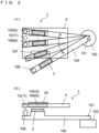
- FIG. 2 illustrates another example of an embodiment of the measurement apparatus according to the present disclosure
- Fig. 2(a) is a top view
- Fig. 2(b) is a side view.
- the elements are seen through a part of the elements (the flow path device 2), and the other part (the arm-like member 100, for example) is illustrated in an overlapped manner to describe an operation.
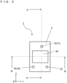
- Figs. 3 to 5 illustrate a part of another example of the measurement apparatus according to the present disclosure.
- Fig. 3 is a top view of the measurement apparatus 1.
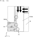
- Fig. 4 illustrates a block diagram schematically showing the configuration of the measurement apparatus 1.
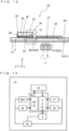
- Fig. 5 is a cross-sectional view of the measurement apparatus 1, and is a cross-sectional view of the measurement apparatus 1 cut along an A-A line illustrated in Fig. 3 .
- the illustration of the mechanism rotationally driving the optical sensor 3 is omitted.
- the measurement apparatus 1 can measure specific particles in liquid as a target.
- the measurement apparatus 1 includes the flow path device 2, the optical sensor 3, and a controller 4.
- the illustration of the mechanism rotationally driving the optical sensor 3 is omitted.
- Liquid (the first liquid such as blood, for example) including specific particles (particles such as white blood cells, for example) and liquid (the second liquid such as PBS, for example) which does not include the particles flow in the flow path device 2.
- the optical sensor 3 is disposed to face the measurement region and the comparison region of the predetermined flow path in the flow path device 2, thus can irradiate the first liquid with light and receive light passing through the first liquid (light reflected after passing through the first liquid, and then passing through the first liquid again and returning).
- the controller 4 can estimate and measure the number of particles, for example, based on an output of the optical sensor 3.
- the first liquid is liquid including particles to be measured, and is a sample when it is an inspection target by the measurement.
- the flow path device 2 is a measurement flow path for measuring the particles in the first liquid.
- the flow path device 2 includes the first flow path 5 and the second flow path 6 both having translucency.
- the first liquid including the particles to be measured flows in the first flow path 5.
- the second liquid for comparison which does not include particles flows in the second flow path 6.
- the first flow path 5 is a flow path for measurement
- the second flow path 6 is a flow path for comparison measurement.
- the first liquid is a sample in an inspection, and is assumed as blood, for example.
- the second liquid is liquid for comparison, and PBS, for example, can be used.
- the optical sensor 3 can sense the particles in the first liquid.
- the optical sensor 3 irradiates each of the first flow path 5 and the second flow path 6 with light, and receives the light passing through each of the first flow path 5 and the second flow path 6 in the measurement.
- the optical sensor 3 includes a light emitting element 7 and a light receiving element 8.
- the light emitting element 7 may be a light emitting diode (LED) or a laser diode (LD), for example, and the light emitting element 7 in the present example is an LED.
- the light receiving element 8 may be a photo diode (PD), for example.
- the controller 4 controls the measurement apparatus 1.
- the controller 4 compares intensity of the light (first light) passing through the first flow path 5 and intensity of the light (second light) passing through the second flow path 6, each of which is obtained by the optical sensor 3, thereby being able to measure the particles in the first liquid. That is to say, the controller 4 calculates a difference of intensity between the first light and the second light, and compares the difference of intensity between the first light and the second light with the standard curve, thereby being able to measure the particles.
- the particles are measured in accordance with a change of the light intensity using a diffusion, absorption and the like of the light of the particles with the optical sensor, when the light intensity is reduced due to the deterioration of an optical element, for example, a measurement result that the number of particles is larger than an original number is erroneously obtained.
- the particles are measured in accordance with the difference of intensity between the first light and the second light, as described above, thus a measurement accuracy can be maintained or improved regardless of the deterioration of the optical element.
- the flow path device 2 has a plate-like shape, for example.
- the flow path device 2 in the present example is formed by mainly bonding a first substrate 9 and a second substrate 10.
- the flow path device 2 includes the first substrate 9 with a groove and the second substrate 10 disposed on a surface of the first substrate 9.
- the second substrate 10 covers an opening of the groove in the first substrate 9. That is to say, the groove of the first substrate 9 and the surface of the second substrate 10 constitute the first flow path 5 and the second flow path 6.
- the flow path device 2 may include a member other than the first substrate 9 and the second substrate 10.
- the data of the standard curve (standard data) needs not necessarily be stored in the controller 4.
- the data is recorded in the other storage medium connected to the controller via network and drawn out with an access to the storage medium for each measurement.
- the controller 4 may turn off the optical sensor 3 while moving the optical sensor 3 after turning on the optical sensor 3 and making the optical sensor 3 output each of the signals S1, S2, and S3.
- the controller 4 may pulse-drive and blink the optical sensor 3 during the measurement. As a result, the deterioration of the light emitting element 7 of the optical sensor 3 can be reduced compared with the case of continuously turning on the optical sensor 3.
Landscapes
- Chemical & Material Sciences (AREA)
- Biochemistry (AREA)
- Physics & Mathematics (AREA)
- Health & Medical Sciences (AREA)
- Life Sciences & Earth Sciences (AREA)
- Analytical Chemistry (AREA)
- General Health & Medical Sciences (AREA)
- General Physics & Mathematics (AREA)
- Immunology (AREA)
- Pathology (AREA)
- Dispersion Chemistry (AREA)
- Optical Measuring Cells (AREA)
- Investigating Or Analysing Materials By Optical Means (AREA)
Claims (4)
- Messvorrichtung (1, 1A), aufweisend:einen optischen Sensor (3),eine Strömungspfadvorrichtung (2, 2A), die eine obere und eine untere Fläche hat, aufweisend einen ersten Strömungspfad (5), in dem eine erste Flüssigkeit, die zu messende Partikel enthält, strömt, und aufweisend einen Messbereich (105), wo die Partikel in der ersten Flüssigkeit mit dem optischen Sensor (3) gemessen werden, einen zweiten Strömungspfad (6), in dem eine zweite Flüssigkeit zum Vergleich, die die Partikel nicht enthält, strömt, und aufweisend einen Vergleichsbereich (106), wo die zweite Flüssigkeit mit dem optischen Sensor (3) gemessen wird, wobei der optische Sensor (3) auf der Seite der oberen Fläche der Strömungspfadvorrichtung (2, 2A) oder auf der Seite der unteren Fläche der Strömungspfadvorrichtung (2, 2A) angeordnet ist,einen Kalibrierungsbereich (107) zum Kalibrieren des optischen Sensors (3), und ein nicht reflektierendes Element (24), das in einem Bereich angeordnet ist, der mit dem ersten Strömungspfad (5) und dem zweiten Strömungspfad (6) auf einer Seite der Strömungspfadvorrichtung (2, 2A) überlappt ist, die dem optischen Sensor (3) gegenüberliegt, und der mit dem Messbereich (105) und dem Vergleichsbereich (106) korrespondiert,ein armartiges Element (100), bei dem der optische Sensor (3), in dem ein lichtemittierendes Element (7) und ein lichtempfangendes Element (8) integral auf einem Substrat angeordnet sind, in einem ersten Ende angeordnet ist, und in dem eine Antriebswelle (101) in einem zweiten Ende angeordnet ist, undeinen Drehantriebsaktuator (102), der mit der Antriebswelle (101) verbunden ist und konfiguriert ist, um das armartige Element (100) in einem vorbestimmten Bereich drehend anzutreiben, wobeijeder von dem Messbereich (105), dem Vergleichsbereich (106) und dem Kalibrierungsbereich (107) als ein Bereich angeordnet ist, der eine Umfangsposition aufweist, entlang der sich der optische Sensor (3) gemäß einem Drehantrieb des armartigen Elements (100) bewegt, und wobeidas nicht reflektierende Element (24) eine Reflexion von Licht blockiert, das von dem lichtemittierenden Element (7) emittiert wird, das jeden von dem ersten Strömungspfad (5) in dem Messbereich (105) und dem zweiten Strömungspfad (6) in dem Vergleichsbereich (106) durchlaufen hat, und Störlicht blockiert, das in den ersten Strömungspfad (5) und den zweiten Strömungspfad (6) von der dem optischen Sensor (3) gegenüberliegenden Seite eintritt.
- Messvorrichtung (1, 1A) gemäß Anspruch 1, wobei
die Strömungspfadvorrichtung (2, 2A) ein nicht reflektierendes Element (107a) aufweist, das auf der dem optischen Sensor (3) gegenüberliegenden Seite oder auf einer dem optischen Sensor (3) zugewandten Seite der Strömungspfadvorrichtung (2, 2A) angeordnet ist, um mit dem Kalibrierungsbereich (107) zu korrespondieren. - Messvorrichtung (1, 1A) gemäß Anspruch 1, wobeidie Strömungspfadvorrichtung (2, 2A) einen ersten Strömungsauslass (13) aufweist, mit dem der erste Strömungspfad (5) verbunden ist und durch den die erste Flüssigkeit in einem Bereich des armartigen Elements (100) herausströmt, unddas armartige Element (100) einen ersten Flüssigkeitsrückgewinnungsbehälter (108) aufweist, der angeordnet ist, um mit dem ersten Strömungsauslass (13) zu korrespondieren, und konfiguriert ist, um die erste Flüssigkeit, die durch den ersten Strömungsauslass (13) herausgeströmt ist, zurückzugewinnen.
- Messvorrichtung (1, 1A) gemäß Anspruch 1, wobei
der Drehantriebsaktuator (102) ein Schrittmotor/Impulsmotor ist.
Applications Claiming Priority (2)
| Application Number | Priority Date | Filing Date | Title |
|---|---|---|---|
| JP2018202597 | 2018-10-29 | ||
| PCT/JP2019/041522 WO2020090582A1 (ja) | 2018-10-29 | 2019-10-23 | 計測装置 |
Publications (3)
| Publication Number | Publication Date |
|---|---|
| EP3875941A1 EP3875941A1 (de) | 2021-09-08 |
| EP3875941A4 EP3875941A4 (de) | 2022-08-17 |
| EP3875941B1 true EP3875941B1 (de) | 2024-07-10 |
Family
ID=70464490
Family Applications (1)
| Application Number | Title | Priority Date | Filing Date |
|---|---|---|---|
| EP19877709.6A Active EP3875941B1 (de) | 2018-10-29 | 2019-10-23 | Messvorrichtung |
Country Status (5)
| Country | Link |
|---|---|
| US (1) | US11802826B2 (de) |
| EP (1) | EP3875941B1 (de) |
| JP (1) | JP7066001B2 (de) |
| CN (1) | CN112888931B (de) |
| WO (1) | WO2020090582A1 (de) |
Families Citing this family (1)
| Publication number | Priority date | Publication date | Assignee | Title |
|---|---|---|---|---|
| EP3748331B1 (de) * | 2018-01-30 | 2023-08-09 | Kyocera Corporation | Messvorrichtung |
Family Cites Families (28)
| Publication number | Priority date | Publication date | Assignee | Title |
|---|---|---|---|---|
| US4063097A (en) * | 1976-09-16 | 1977-12-13 | General Electric Company | X-ray body scanner for computerized tomography comprising inner fluid container surrounded by outer fluid container |
| US4234539A (en) * | 1979-08-23 | 1980-11-18 | Coulter Electronics, Inc. | Apparatus for monitoring chemical reactions and employing moving photometer means |
| US4623797A (en) * | 1983-06-27 | 1986-11-18 | Mts Vektronics Corporation | Event scanning |
| US5727111A (en) * | 1995-06-19 | 1998-03-10 | Sony Corporation | Optical pick-up and light detecting cover therefor |
| JP3337404B2 (ja) * | 1997-09-22 | 2002-10-21 | シャープ株式会社 | 感度補正機能付きほこりセンサ装置 |
| US7423750B2 (en) * | 2001-11-29 | 2008-09-09 | Applera Corporation | Configurations, systems, and methods for optical scanning with at least one first relative angular motion and at least one second angular motion or at least one linear motion |
| JP4033589B2 (ja) | 1999-09-06 | 2008-01-16 | 隆史 伊永 | 分子拡散を用いた反応法およびその装置 |
| US7294513B2 (en) * | 2002-07-24 | 2007-11-13 | Wyatt Technology Corporation | Method and apparatus for characterizing solutions of small particles |
| KR100926955B1 (ko) * | 2005-05-13 | 2009-11-17 | 쇼와 덴코 가부시키가이샤 | 시차 굴절률 측정용 장치 |
| DE102006043977A1 (de) * | 2006-09-19 | 2008-03-27 | Sick Ag | Optoelektronische Sensoreinheit und Verfahren zum Betreiben einer optoelektronischen Sensoreinheit |
| JP4663614B2 (ja) * | 2006-10-18 | 2011-04-06 | 株式会社日立メディアエレクトロニクス | 光ピックアップおよび光学的情報記録再生装置 |
| JP4752791B2 (ja) * | 2007-02-28 | 2011-08-17 | 株式会社デンソー | 液体性状検出方法 |
| JP2009014702A (ja) * | 2007-06-06 | 2009-01-22 | Hitachi Ltd | 微粒子検出装置及び微粒子検出方法 |
| JP2009002830A (ja) * | 2007-06-22 | 2009-01-08 | Hitachi Omron Terminal Solutions Corp | 発光量を補正可能な光センサ、それを用いた紙葉類識別装置及びその補正方法 |
| JP2009145022A (ja) | 2007-12-18 | 2009-07-02 | Daikin Ind Ltd | 調湿装置 |
| WO2009145022A1 (ja) | 2008-05-27 | 2009-12-03 | コニカミノルタエムジー株式会社 | 微細流路を備えたマイクロチップ |
| GB2516780B (en) * | 2009-05-27 | 2015-07-15 | Silixa Ltd | Apparatus for optical sensing |
| DE102009043524A1 (de) * | 2009-09-30 | 2011-03-31 | Siemens Healthcare Diagnostics Products Gmbh | Vorrichtung für die photometrische Untersuchung von Proben |
| JP5567526B2 (ja) * | 2010-11-12 | 2014-08-06 | 株式会社日立ハイテクノロジーズ | 分析装置および分析方法 |
| JP6239243B2 (ja) * | 2013-02-08 | 2017-11-29 | エフ.ホフマン−ラ ロシュ アーゲーF. Hoffmann−La Roche Aktiengesellschaft | 自動分析装置 |
| US9140648B2 (en) * | 2013-03-12 | 2015-09-22 | Ecolab Usa Inc. | Fluorometer with multiple detection channels |
| JP6081830B2 (ja) * | 2013-03-12 | 2017-02-15 | 新日本無線株式会社 | 反射型フォトセンサを用いた位置検出装置 |
| ES2711364T3 (es) * | 2013-03-15 | 2019-05-03 | Iris Int Inc | Sistemas y métodos de célula de flujo para el análisis de partículas en muestras de sangre |
| JP6082329B2 (ja) * | 2013-08-07 | 2017-02-15 | 倉敷紡績株式会社 | 濃度測定装置及び濃度測定方法 |
| SG11201706777QA (en) * | 2015-02-19 | 2017-09-28 | Premium Genetics (Uk) Ltd | Scanning infrared measurement system |
| JP6620983B2 (ja) * | 2015-12-28 | 2019-12-18 | パナソニックIpマネジメント株式会社 | 粒子検出センサ |
| EP3477284A1 (de) * | 2016-06-22 | 2019-05-01 | Kyocera Corporation | Instrument zur feinpartikelmessung |
| WO2019204841A1 (de) * | 2018-04-23 | 2019-10-31 | Meon Medical Solutions Gmbh & Co Kg | Automatischer analysator und optisches messverfahren zur gewinnung von messsignalen von flüssigen medien |
-
2019
- 2019-10-23 CN CN201980069602.3A patent/CN112888931B/zh active Active
- 2019-10-23 JP JP2020553815A patent/JP7066001B2/ja active Active
- 2019-10-23 WO PCT/JP2019/041522 patent/WO2020090582A1/ja not_active Ceased
- 2019-10-23 US US17/286,528 patent/US11802826B2/en active Active
- 2019-10-23 EP EP19877709.6A patent/EP3875941B1/de active Active
Also Published As
| Publication number | Publication date |
|---|---|
| CN112888931A (zh) | 2021-06-01 |
| CN112888931B (zh) | 2024-07-23 |
| EP3875941A1 (de) | 2021-09-08 |
| US20220018751A1 (en) | 2022-01-20 |
| US11802826B2 (en) | 2023-10-31 |
| JP7066001B2 (ja) | 2022-05-12 |
| WO2020090582A1 (ja) | 2020-05-07 |
| JPWO2020090582A1 (ja) | 2021-09-16 |
| EP3875941A4 (de) | 2022-08-17 |
Similar Documents
| Publication | Publication Date | Title |
|---|---|---|
| US9535004B2 (en) | Surface plasmon resonance fluorescence analysis method and surface plasmon resonance fluorescence analysis device | |
| JP7080334B2 (ja) | 検体処理デバイスへの検体導入方法 | |
| CN1688865A (zh) | 光学对准检测系统 | |
| US10495576B2 (en) | Surface-plasmon enhanced fluorescence measurement method, surface-plasmon enhanced fluorescence measurement device, and analytical chip | |
| JP7213932B2 (ja) | 流路デバイスおよび計測装置 | |
| US11802826B2 (en) | Measurement apparatus | |
| JPWO2018034143A1 (ja) | 測定方法、測定装置および測定システム | |
| JP6766820B2 (ja) | 光学式検体検出システム | |
| JPWO2016132945A1 (ja) | 反応方法および反応装置 | |
| WO2018034208A1 (ja) | 測定方法 | |
| JP6922907B2 (ja) | 反応方法、ならびにこれを行う反応システムおよび反応装置 | |
| US12540894B2 (en) | Position adjusting method, microparticle analysis device, and program | |
| US10921340B2 (en) | Liquid feeding method, and detection system and detection device for carrying out said method | |
| JP6956695B2 (ja) | 液体供給デバイス | |
| JP6923385B2 (ja) | 流路部材および微粒子計測器 | |
| WO2018179950A1 (ja) | 検体検出システム用センサーチップ |
Legal Events
| Date | Code | Title | Description |
|---|---|---|---|
| STAA | Information on the status of an ep patent application or granted ep patent |
Free format text: STATUS: THE INTERNATIONAL PUBLICATION HAS BEEN MADE |
|
| PUAI | Public reference made under article 153(3) epc to a published international application that has entered the european phase |
Free format text: ORIGINAL CODE: 0009012 |
|
| STAA | Information on the status of an ep patent application or granted ep patent |
Free format text: STATUS: REQUEST FOR EXAMINATION WAS MADE |
|
| 17P | Request for examination filed |
Effective date: 20210413 |
|
| AK | Designated contracting states |
Kind code of ref document: A1 Designated state(s): AL AT BE BG CH CY CZ DE DK EE ES FI FR GB GR HR HU IE IS IT LI LT LU LV MC MK MT NL NO PL PT RO RS SE SI SK SM TR |
|
| DAV | Request for validation of the european patent (deleted) | ||
| DAX | Request for extension of the european patent (deleted) | ||
| RIN1 | Information on inventor provided before grant (corrected) |
Inventor name: MASUDA, YUJI |
|
| A4 | Supplementary search report drawn up and despatched |
Effective date: 20220718 |
|
| RIC1 | Information provided on ipc code assigned before grant |
Ipc: G01N 15/00 20060101ALN20220712BHEP Ipc: G01N 35/00 20060101ALI20220712BHEP Ipc: G01N 21/59 20060101ALI20220712BHEP Ipc: G01N 15/06 20060101AFI20220712BHEP |
|
| P01 | Opt-out of the competence of the unified patent court (upc) registered |
Effective date: 20230505 |
|
| GRAP | Despatch of communication of intention to grant a patent |
Free format text: ORIGINAL CODE: EPIDOSNIGR1 |
|
| STAA | Information on the status of an ep patent application or granted ep patent |
Free format text: STATUS: GRANT OF PATENT IS INTENDED |
|
| RIC1 | Information provided on ipc code assigned before grant |
Ipc: G01N 15/00 20060101ALN20240229BHEP Ipc: G01N 35/00 20060101ALI20240229BHEP Ipc: G01N 21/59 20060101ALI20240229BHEP Ipc: G01N 15/06 20060101AFI20240229BHEP |
|
| RIC1 | Information provided on ipc code assigned before grant |
Ipc: G01N 15/00 20060101ALN20240319BHEP Ipc: G01N 35/00 20060101ALI20240319BHEP Ipc: G01N 21/59 20060101ALI20240319BHEP Ipc: G01N 15/06 20060101AFI20240319BHEP |
|
| INTG | Intention to grant announced |
Effective date: 20240403 |
|
| GRAS | Grant fee paid |
Free format text: ORIGINAL CODE: EPIDOSNIGR3 |
|
| GRAA | (expected) grant |
Free format text: ORIGINAL CODE: 0009210 |
|
| STAA | Information on the status of an ep patent application or granted ep patent |
Free format text: STATUS: THE PATENT HAS BEEN GRANTED |
|
| AK | Designated contracting states |
Kind code of ref document: B1 Designated state(s): AL AT BE BG CH CY CZ DE DK EE ES FI FR GB GR HR HU IE IS IT LI LT LU LV MC MK MT NL NO PL PT RO RS SE SI SK SM TR |
|
| REG | Reference to a national code |
Ref country code: CH Ref legal event code: EP |
|
| REG | Reference to a national code |
Ref country code: DE Ref legal event code: R096 Ref document number: 602019055145 Country of ref document: DE |
|
| REG | Reference to a national code |
Ref country code: LT Ref legal event code: MG9D |
|
| REG | Reference to a national code |
Ref country code: NL Ref legal event code: MP Effective date: 20240710 |
|
| PG25 | Lapsed in a contracting state [announced via postgrant information from national office to epo] |
Ref country code: PT Free format text: LAPSE BECAUSE OF FAILURE TO SUBMIT A TRANSLATION OF THE DESCRIPTION OR TO PAY THE FEE WITHIN THE PRESCRIBED TIME-LIMIT Effective date: 20241111 |
|
| REG | Reference to a national code |
Ref country code: AT Ref legal event code: MK05 Ref document number: 1702428 Country of ref document: AT Kind code of ref document: T Effective date: 20240710 |
|
| PG25 | Lapsed in a contracting state [announced via postgrant information from national office to epo] |
Ref country code: NL Free format text: LAPSE BECAUSE OF FAILURE TO SUBMIT A TRANSLATION OF THE DESCRIPTION OR TO PAY THE FEE WITHIN THE PRESCRIBED TIME-LIMIT Effective date: 20240710 |
|
| PG25 | Lapsed in a contracting state [announced via postgrant information from national office to epo] |
Ref country code: PT Free format text: LAPSE BECAUSE OF FAILURE TO SUBMIT A TRANSLATION OF THE DESCRIPTION OR TO PAY THE FEE WITHIN THE PRESCRIBED TIME-LIMIT Effective date: 20241111 Ref country code: NL Free format text: LAPSE BECAUSE OF FAILURE TO SUBMIT A TRANSLATION OF THE DESCRIPTION OR TO PAY THE FEE WITHIN THE PRESCRIBED TIME-LIMIT Effective date: 20240710 |
|
| PGFP | Annual fee paid to national office [announced via postgrant information from national office to epo] |
Ref country code: DE Payment date: 20240828 Year of fee payment: 6 |
|
| PG25 | Lapsed in a contracting state [announced via postgrant information from national office to epo] |
Ref country code: NO Free format text: LAPSE BECAUSE OF FAILURE TO SUBMIT A TRANSLATION OF THE DESCRIPTION OR TO PAY THE FEE WITHIN THE PRESCRIBED TIME-LIMIT Effective date: 20241010 |
|
| PG25 | Lapsed in a contracting state [announced via postgrant information from national office to epo] |
Ref country code: GR Free format text: LAPSE BECAUSE OF FAILURE TO SUBMIT A TRANSLATION OF THE DESCRIPTION OR TO PAY THE FEE WITHIN THE PRESCRIBED TIME-LIMIT Effective date: 20241011 Ref country code: FI Free format text: LAPSE BECAUSE OF FAILURE TO SUBMIT A TRANSLATION OF THE DESCRIPTION OR TO PAY THE FEE WITHIN THE PRESCRIBED TIME-LIMIT Effective date: 20240710 Ref country code: PL Free format text: LAPSE BECAUSE OF FAILURE TO SUBMIT A TRANSLATION OF THE DESCRIPTION OR TO PAY THE FEE WITHIN THE PRESCRIBED TIME-LIMIT Effective date: 20240710 |
|
| PG25 | Lapsed in a contracting state [announced via postgrant information from national office to epo] |
Ref country code: BG Free format text: LAPSE BECAUSE OF FAILURE TO SUBMIT A TRANSLATION OF THE DESCRIPTION OR TO PAY THE FEE WITHIN THE PRESCRIBED TIME-LIMIT Effective date: 20240710 |
|
| PG25 | Lapsed in a contracting state [announced via postgrant information from national office to epo] |
Ref country code: LV Free format text: LAPSE BECAUSE OF FAILURE TO SUBMIT A TRANSLATION OF THE DESCRIPTION OR TO PAY THE FEE WITHIN THE PRESCRIBED TIME-LIMIT Effective date: 20240710 |
|
| PG25 | Lapsed in a contracting state [announced via postgrant information from national office to epo] |
Ref country code: AT Free format text: LAPSE BECAUSE OF FAILURE TO SUBMIT A TRANSLATION OF THE DESCRIPTION OR TO PAY THE FEE WITHIN THE PRESCRIBED TIME-LIMIT Effective date: 20240710 Ref country code: IS Free format text: LAPSE BECAUSE OF FAILURE TO SUBMIT A TRANSLATION OF THE DESCRIPTION OR TO PAY THE FEE WITHIN THE PRESCRIBED TIME-LIMIT Effective date: 20241110 |
|
| PG25 | Lapsed in a contracting state [announced via postgrant information from national office to epo] |
Ref country code: HR Free format text: LAPSE BECAUSE OF FAILURE TO SUBMIT A TRANSLATION OF THE DESCRIPTION OR TO PAY THE FEE WITHIN THE PRESCRIBED TIME-LIMIT Effective date: 20240710 |
|
| PG25 | Lapsed in a contracting state [announced via postgrant information from national office to epo] |
Ref country code: ES Free format text: LAPSE BECAUSE OF FAILURE TO SUBMIT A TRANSLATION OF THE DESCRIPTION OR TO PAY THE FEE WITHIN THE PRESCRIBED TIME-LIMIT Effective date: 20240710 Ref country code: RS Free format text: LAPSE BECAUSE OF FAILURE TO SUBMIT A TRANSLATION OF THE DESCRIPTION OR TO PAY THE FEE WITHIN THE PRESCRIBED TIME-LIMIT Effective date: 20241010 |
|
| PG25 | Lapsed in a contracting state [announced via postgrant information from national office to epo] |
Ref country code: RS Free format text: LAPSE BECAUSE OF FAILURE TO SUBMIT A TRANSLATION OF THE DESCRIPTION OR TO PAY THE FEE WITHIN THE PRESCRIBED TIME-LIMIT Effective date: 20241010 Ref country code: PL Free format text: LAPSE BECAUSE OF FAILURE TO SUBMIT A TRANSLATION OF THE DESCRIPTION OR TO PAY THE FEE WITHIN THE PRESCRIBED TIME-LIMIT Effective date: 20240710 Ref country code: NO Free format text: LAPSE BECAUSE OF FAILURE TO SUBMIT A TRANSLATION OF THE DESCRIPTION OR TO PAY THE FEE WITHIN THE PRESCRIBED TIME-LIMIT Effective date: 20241010 Ref country code: LV Free format text: LAPSE BECAUSE OF FAILURE TO SUBMIT A TRANSLATION OF THE DESCRIPTION OR TO PAY THE FEE WITHIN THE PRESCRIBED TIME-LIMIT Effective date: 20240710 Ref country code: IS Free format text: LAPSE BECAUSE OF FAILURE TO SUBMIT A TRANSLATION OF THE DESCRIPTION OR TO PAY THE FEE WITHIN THE PRESCRIBED TIME-LIMIT Effective date: 20241110 Ref country code: HR Free format text: LAPSE BECAUSE OF FAILURE TO SUBMIT A TRANSLATION OF THE DESCRIPTION OR TO PAY THE FEE WITHIN THE PRESCRIBED TIME-LIMIT Effective date: 20240710 Ref country code: GR Free format text: LAPSE BECAUSE OF FAILURE TO SUBMIT A TRANSLATION OF THE DESCRIPTION OR TO PAY THE FEE WITHIN THE PRESCRIBED TIME-LIMIT Effective date: 20241011 Ref country code: FI Free format text: LAPSE BECAUSE OF FAILURE TO SUBMIT A TRANSLATION OF THE DESCRIPTION OR TO PAY THE FEE WITHIN THE PRESCRIBED TIME-LIMIT Effective date: 20240710 Ref country code: ES Free format text: LAPSE BECAUSE OF FAILURE TO SUBMIT A TRANSLATION OF THE DESCRIPTION OR TO PAY THE FEE WITHIN THE PRESCRIBED TIME-LIMIT Effective date: 20240710 Ref country code: BG Free format text: LAPSE BECAUSE OF FAILURE TO SUBMIT A TRANSLATION OF THE DESCRIPTION OR TO PAY THE FEE WITHIN THE PRESCRIBED TIME-LIMIT Effective date: 20240710 Ref country code: AT Free format text: LAPSE BECAUSE OF FAILURE TO SUBMIT A TRANSLATION OF THE DESCRIPTION OR TO PAY THE FEE WITHIN THE PRESCRIBED TIME-LIMIT Effective date: 20240710 |
|
| REG | Reference to a national code |
Ref country code: DE Ref legal event code: R097 Ref document number: 602019055145 Country of ref document: DE |
|
| PG25 | Lapsed in a contracting state [announced via postgrant information from national office to epo] |
Ref country code: DK Free format text: LAPSE BECAUSE OF FAILURE TO SUBMIT A TRANSLATION OF THE DESCRIPTION OR TO PAY THE FEE WITHIN THE PRESCRIBED TIME-LIMIT Effective date: 20240710 Ref country code: SM Free format text: LAPSE BECAUSE OF FAILURE TO SUBMIT A TRANSLATION OF THE DESCRIPTION OR TO PAY THE FEE WITHIN THE PRESCRIBED TIME-LIMIT Effective date: 20240710 Ref country code: RO Free format text: LAPSE BECAUSE OF FAILURE TO SUBMIT A TRANSLATION OF THE DESCRIPTION OR TO PAY THE FEE WITHIN THE PRESCRIBED TIME-LIMIT Effective date: 20240710 |
|
| PG25 | Lapsed in a contracting state [announced via postgrant information from national office to epo] |
Ref country code: EE Free format text: LAPSE BECAUSE OF FAILURE TO SUBMIT A TRANSLATION OF THE DESCRIPTION OR TO PAY THE FEE WITHIN THE PRESCRIBED TIME-LIMIT Effective date: 20240710 |
|
| PG25 | Lapsed in a contracting state [announced via postgrant information from national office to epo] |
Ref country code: CZ Free format text: LAPSE BECAUSE OF FAILURE TO SUBMIT A TRANSLATION OF THE DESCRIPTION OR TO PAY THE FEE WITHIN THE PRESCRIBED TIME-LIMIT Effective date: 20240710 |
|
| PG25 | Lapsed in a contracting state [announced via postgrant information from national office to epo] |
Ref country code: IT Free format text: LAPSE BECAUSE OF FAILURE TO SUBMIT A TRANSLATION OF THE DESCRIPTION OR TO PAY THE FEE WITHIN THE PRESCRIBED TIME-LIMIT Effective date: 20240710 Ref country code: SK Free format text: LAPSE BECAUSE OF FAILURE TO SUBMIT A TRANSLATION OF THE DESCRIPTION OR TO PAY THE FEE WITHIN THE PRESCRIBED TIME-LIMIT Effective date: 20240710 |
|
| PLBE | No opposition filed within time limit |
Free format text: ORIGINAL CODE: 0009261 |
|
| STAA | Information on the status of an ep patent application or granted ep patent |
Free format text: STATUS: NO OPPOSITION FILED WITHIN TIME LIMIT |
|
| REG | Reference to a national code |
Ref country code: CH Ref legal event code: PL |
|
| 26N | No opposition filed |
Effective date: 20250411 |
|
| GBPC | Gb: european patent ceased through non-payment of renewal fee |
Effective date: 20241023 |
|
| PG25 | Lapsed in a contracting state [announced via postgrant information from national office to epo] |
Ref country code: MC Free format text: LAPSE BECAUSE OF FAILURE TO SUBMIT A TRANSLATION OF THE DESCRIPTION OR TO PAY THE FEE WITHIN THE PRESCRIBED TIME-LIMIT Effective date: 20240710 |
|
| PG25 | Lapsed in a contracting state [announced via postgrant information from national office to epo] |
Ref country code: GB Free format text: LAPSE BECAUSE OF NON-PAYMENT OF DUE FEES Effective date: 20241023 |
|
| PG25 | Lapsed in a contracting state [announced via postgrant information from national office to epo] |
Ref country code: LU Free format text: LAPSE BECAUSE OF NON-PAYMENT OF DUE FEES Effective date: 20241023 Ref country code: BE Free format text: LAPSE BECAUSE OF NON-PAYMENT OF DUE FEES Effective date: 20241031 |
|
| PG25 | Lapsed in a contracting state [announced via postgrant information from national office to epo] |
Ref country code: FR Free format text: LAPSE BECAUSE OF NON-PAYMENT OF DUE FEES Effective date: 20241031 |
|
| PG25 | Lapsed in a contracting state [announced via postgrant information from national office to epo] |
Ref country code: CH Free format text: LAPSE BECAUSE OF NON-PAYMENT OF DUE FEES Effective date: 20241031 |
|
| REG | Reference to a national code |
Ref country code: BE Ref legal event code: MM Effective date: 20241031 |
|
| PG25 | Lapsed in a contracting state [announced via postgrant information from national office to epo] |
Ref country code: SE Free format text: LAPSE BECAUSE OF FAILURE TO SUBMIT A TRANSLATION OF THE DESCRIPTION OR TO PAY THE FEE WITHIN THE PRESCRIBED TIME-LIMIT Effective date: 20240710 |
|
| PG25 | Lapsed in a contracting state [announced via postgrant information from national office to epo] |
Ref country code: IE Free format text: LAPSE BECAUSE OF NON-PAYMENT OF DUE FEES Effective date: 20241023 |
|
| PG25 | Lapsed in a contracting state [announced via postgrant information from national office to epo] |
Ref country code: CY Free format text: LAPSE BECAUSE OF FAILURE TO SUBMIT A TRANSLATION OF THE DESCRIPTION OR TO PAY THE FEE WITHIN THE PRESCRIBED TIME-LIMIT; INVALID AB INITIO Effective date: 20191023 |
|
| PG25 | Lapsed in a contracting state [announced via postgrant information from national office to epo] |
Ref country code: HU Free format text: LAPSE BECAUSE OF FAILURE TO SUBMIT A TRANSLATION OF THE DESCRIPTION OR TO PAY THE FEE WITHIN THE PRESCRIBED TIME-LIMIT; INVALID AB INITIO Effective date: 20191023 |