EP3875434B1 - Composite positive electrode active material for lithium secondary battery, preparation method thereof, and lithium secondary battery including positive electrode including the same - Google Patents
Composite positive electrode active material for lithium secondary battery, preparation method thereof, and lithium secondary battery including positive electrode including the same Download PDFInfo
- Publication number
- EP3875434B1 EP3875434B1 EP21161111.6A EP21161111A EP3875434B1 EP 3875434 B1 EP3875434 B1 EP 3875434B1 EP 21161111 A EP21161111 A EP 21161111A EP 3875434 B1 EP3875434 B1 EP 3875434B1
- Authority
- EP
- European Patent Office
- Prior art keywords
- active material
- positive electrode
- cobalt
- electrode active
- nickel
- Prior art date
- Legal status (The legal status is an assumption and is not a legal conclusion. Google has not performed a legal analysis and makes no representation as to the accuracy of the status listed.)
- Active
Links
Images


Classifications
-
- H—ELECTRICITY
- H01—ELECTRIC ELEMENTS
- H01M—PROCESSES OR MEANS, e.g. BATTERIES, FOR THE DIRECT CONVERSION OF CHEMICAL ENERGY INTO ELECTRICAL ENERGY
- H01M4/00—Electrodes
- H01M4/02—Electrodes composed of, or comprising, active material
- H01M4/62—Selection of inactive substances as ingredients for active masses, e.g. binders, fillers
- H01M4/628—Inhibitors, e.g. gassing inhibitors, corrosion inhibitors
-
- C—CHEMISTRY; METALLURGY
- C01—INORGANIC CHEMISTRY
- C01B—NON-METALLIC ELEMENTS; COMPOUNDS THEREOF; METALLOIDS OR COMPOUNDS THEREOF NOT COVERED BY SUBCLASS C01C
- C01B35/00—Boron; Compounds thereof
- C01B35/02—Boron; Borides
- C01B35/04—Metal borides
-
- C—CHEMISTRY; METALLURGY
- C01—INORGANIC CHEMISTRY
- C01G—COMPOUNDS CONTAINING METALS NOT COVERED BY SUBCLASSES C01D OR C01F
- C01G53/00—Compounds of nickel
- C01G53/40—Complex oxides containing nickel and at least one other metal element
- C01G53/42—Complex oxides containing nickel and at least one other metal element containing alkali metals, e.g. LiNiO2
- C01G53/44—Complex oxides containing nickel and at least one other metal element containing alkali metals, e.g. LiNiO2 containing manganese
- C01G53/50—Complex oxides containing nickel and at least one other metal element containing alkali metals, e.g. LiNiO2 containing manganese of the type (MnO2)n-, e.g. Li(NixMn1-x)O2 or Li(MyNixMn1-x-y)O2
-
- H—ELECTRICITY
- H01—ELECTRIC ELEMENTS
- H01M—PROCESSES OR MEANS, e.g. BATTERIES, FOR THE DIRECT CONVERSION OF CHEMICAL ENERGY INTO ELECTRICAL ENERGY
- H01M10/00—Secondary cells; Manufacture thereof
- H01M10/05—Accumulators with non-aqueous electrolyte
- H01M10/052—Li-accumulators
-
- H—ELECTRICITY
- H01—ELECTRIC ELEMENTS
- H01M—PROCESSES OR MEANS, e.g. BATTERIES, FOR THE DIRECT CONVERSION OF CHEMICAL ENERGY INTO ELECTRICAL ENERGY
- H01M10/00—Secondary cells; Manufacture thereof
- H01M10/05—Accumulators with non-aqueous electrolyte
- H01M10/052—Li-accumulators
- H01M10/0525—Rocking-chair batteries, i.e. batteries with lithium insertion or intercalation in both electrodes; Lithium-ion batteries
-
- H—ELECTRICITY
- H01—ELECTRIC ELEMENTS
- H01M—PROCESSES OR MEANS, e.g. BATTERIES, FOR THE DIRECT CONVERSION OF CHEMICAL ENERGY INTO ELECTRICAL ENERGY
- H01M4/00—Electrodes
- H01M4/02—Electrodes composed of, or comprising, active material
- H01M4/04—Processes of manufacture in general
-
- H—ELECTRICITY
- H01—ELECTRIC ELEMENTS
- H01M—PROCESSES OR MEANS, e.g. BATTERIES, FOR THE DIRECT CONVERSION OF CHEMICAL ENERGY INTO ELECTRICAL ENERGY
- H01M4/00—Electrodes
- H01M4/02—Electrodes composed of, or comprising, active material
- H01M4/13—Electrodes for accumulators with non-aqueous electrolyte, e.g. for lithium-accumulators; Processes of manufacture thereof
- H01M4/139—Processes of manufacture
- H01M4/1391—Processes of manufacture of electrodes based on mixed oxides or hydroxides, or on mixtures of oxides or hydroxides, e.g. LiCoOx
-
- H—ELECTRICITY
- H01—ELECTRIC ELEMENTS
- H01M—PROCESSES OR MEANS, e.g. BATTERIES, FOR THE DIRECT CONVERSION OF CHEMICAL ENERGY INTO ELECTRICAL ENERGY
- H01M4/00—Electrodes
- H01M4/02—Electrodes composed of, or comprising, active material
- H01M4/36—Selection of substances as active materials, active masses, active liquids
- H01M4/362—Composites
- H01M4/366—Composites as layered products
-
- H—ELECTRICITY
- H01—ELECTRIC ELEMENTS
- H01M—PROCESSES OR MEANS, e.g. BATTERIES, FOR THE DIRECT CONVERSION OF CHEMICAL ENERGY INTO ELECTRICAL ENERGY
- H01M4/00—Electrodes
- H01M4/02—Electrodes composed of, or comprising, active material
- H01M4/36—Selection of substances as active materials, active masses, active liquids
- H01M4/48—Selection of substances as active materials, active masses, active liquids of inorganic oxides or hydroxides
- H01M4/50—Selection of substances as active materials, active masses, active liquids of inorganic oxides or hydroxides of manganese
- H01M4/505—Selection of substances as active materials, active masses, active liquids of inorganic oxides or hydroxides of manganese of mixed oxides or hydroxides containing manganese for inserting or intercalating light metals, e.g. LiMn2O4 or LiMn2OxFy
-
- H—ELECTRICITY
- H01—ELECTRIC ELEMENTS
- H01M—PROCESSES OR MEANS, e.g. BATTERIES, FOR THE DIRECT CONVERSION OF CHEMICAL ENERGY INTO ELECTRICAL ENERGY
- H01M4/00—Electrodes
- H01M4/02—Electrodes composed of, or comprising, active material
- H01M4/36—Selection of substances as active materials, active masses, active liquids
- H01M4/48—Selection of substances as active materials, active masses, active liquids of inorganic oxides or hydroxides
- H01M4/52—Selection of substances as active materials, active masses, active liquids of inorganic oxides or hydroxides of nickel, cobalt or iron
- H01M4/525—Selection of substances as active materials, active masses, active liquids of inorganic oxides or hydroxides of nickel, cobalt or iron of mixed oxides or hydroxides containing iron, cobalt or nickel for inserting or intercalating light metals, e.g. LiNiO2, LiCoO2 or LiCoOxFy
-
- H—ELECTRICITY
- H01—ELECTRIC ELEMENTS
- H01M—PROCESSES OR MEANS, e.g. BATTERIES, FOR THE DIRECT CONVERSION OF CHEMICAL ENERGY INTO ELECTRICAL ENERGY
- H01M4/00—Electrodes
- H01M4/02—Electrodes composed of, or comprising, active material
- H01M4/62—Selection of inactive substances as ingredients for active masses, e.g. binders, fillers
- H01M4/624—Electric conductive fillers
-
- C—CHEMISTRY; METALLURGY
- C01—INORGANIC CHEMISTRY
- C01P—INDEXING SCHEME RELATING TO STRUCTURAL AND PHYSICAL ASPECTS OF SOLID INORGANIC COMPOUNDS
- C01P2002/00—Crystal-structural characteristics
- C01P2002/70—Crystal-structural characteristics defined by measured X-ray, neutron or electron diffraction data
- C01P2002/72—Crystal-structural characteristics defined by measured X-ray, neutron or electron diffraction data by d-values or two theta-values, e.g. as X-ray diagram
-
- C—CHEMISTRY; METALLURGY
- C01—INORGANIC CHEMISTRY
- C01P—INDEXING SCHEME RELATING TO STRUCTURAL AND PHYSICAL ASPECTS OF SOLID INORGANIC COMPOUNDS
- C01P2002/00—Crystal-structural characteristics
- C01P2002/70—Crystal-structural characteristics defined by measured X-ray, neutron or electron diffraction data
- C01P2002/74—Crystal-structural characteristics defined by measured X-ray, neutron or electron diffraction data by peak-intensities or a ratio thereof only
-
- C—CHEMISTRY; METALLURGY
- C01—INORGANIC CHEMISTRY
- C01P—INDEXING SCHEME RELATING TO STRUCTURAL AND PHYSICAL ASPECTS OF SOLID INORGANIC COMPOUNDS
- C01P2002/00—Crystal-structural characteristics
- C01P2002/80—Crystal-structural characteristics defined by measured data other than those specified in group C01P2002/70
- C01P2002/85—Crystal-structural characteristics defined by measured data other than those specified in group C01P2002/70 by XPS, EDX or EDAX data
-
- C—CHEMISTRY; METALLURGY
- C01—INORGANIC CHEMISTRY
- C01P—INDEXING SCHEME RELATING TO STRUCTURAL AND PHYSICAL ASPECTS OF SOLID INORGANIC COMPOUNDS
- C01P2004/00—Particle morphology
- C01P2004/01—Particle morphology depicted by an image
- C01P2004/03—Particle morphology depicted by an image obtained by SEM
-
- C—CHEMISTRY; METALLURGY
- C01—INORGANIC CHEMISTRY
- C01P—INDEXING SCHEME RELATING TO STRUCTURAL AND PHYSICAL ASPECTS OF SOLID INORGANIC COMPOUNDS
- C01P2004/00—Particle morphology
- C01P2004/01—Particle morphology depicted by an image
- C01P2004/04—Particle morphology depicted by an image obtained by TEM, STEM, STM or AFM
-
- C—CHEMISTRY; METALLURGY
- C01—INORGANIC CHEMISTRY
- C01P—INDEXING SCHEME RELATING TO STRUCTURAL AND PHYSICAL ASPECTS OF SOLID INORGANIC COMPOUNDS
- C01P2004/00—Particle morphology
- C01P2004/20—Particle morphology extending in two dimensions, e.g. plate-like
- C01P2004/24—Nanoplates, i.e. plate-like particles with a thickness from 1-100 nanometer
-
- C—CHEMISTRY; METALLURGY
- C01—INORGANIC CHEMISTRY
- C01P—INDEXING SCHEME RELATING TO STRUCTURAL AND PHYSICAL ASPECTS OF SOLID INORGANIC COMPOUNDS
- C01P2004/00—Particle morphology
- C01P2004/60—Particles characterised by their size
- C01P2004/64—Nanometer sized, i.e. from 1-100 nanometer
-
- C—CHEMISTRY; METALLURGY
- C01—INORGANIC CHEMISTRY
- C01P—INDEXING SCHEME RELATING TO STRUCTURAL AND PHYSICAL ASPECTS OF SOLID INORGANIC COMPOUNDS
- C01P2004/00—Particle morphology
- C01P2004/80—Particles consisting of a mixture of two or more inorganic phases
-
- C—CHEMISTRY; METALLURGY
- C01—INORGANIC CHEMISTRY
- C01P—INDEXING SCHEME RELATING TO STRUCTURAL AND PHYSICAL ASPECTS OF SOLID INORGANIC COMPOUNDS
- C01P2006/00—Physical properties of inorganic compounds
- C01P2006/40—Electric properties
-
- H—ELECTRICITY
- H01—ELECTRIC ELEMENTS
- H01M—PROCESSES OR MEANS, e.g. BATTERIES, FOR THE DIRECT CONVERSION OF CHEMICAL ENERGY INTO ELECTRICAL ENERGY
- H01M4/00—Electrodes
- H01M4/02—Electrodes composed of, or comprising, active material
- H01M2004/026—Electrodes composed of, or comprising, active material characterised by the polarity
- H01M2004/028—Positive electrodes
-
- H—ELECTRICITY
- H01—ELECTRIC ELEMENTS
- H01M—PROCESSES OR MEANS, e.g. BATTERIES, FOR THE DIRECT CONVERSION OF CHEMICAL ENERGY INTO ELECTRICAL ENERGY
- H01M2220/00—Batteries for particular applications
- H01M2220/20—Batteries in motive systems, e.g. vehicle, ship, plane
-
- H—ELECTRICITY
- H01—ELECTRIC ELEMENTS
- H01M—PROCESSES OR MEANS, e.g. BATTERIES, FOR THE DIRECT CONVERSION OF CHEMICAL ENERGY INTO ELECTRICAL ENERGY
- H01M2220/00—Batteries for particular applications
- H01M2220/30—Batteries in portable systems, e.g. mobile phone, laptop
-
- Y—GENERAL TAGGING OF NEW TECHNOLOGICAL DEVELOPMENTS; GENERAL TAGGING OF CROSS-SECTIONAL TECHNOLOGIES SPANNING OVER SEVERAL SECTIONS OF THE IPC; TECHNICAL SUBJECTS COVERED BY FORMER USPC CROSS-REFERENCE ART COLLECTIONS [XRACs] AND DIGESTS
- Y02—TECHNOLOGIES OR APPLICATIONS FOR MITIGATION OR ADAPTATION AGAINST CLIMATE CHANGE
- Y02E—REDUCTION OF GREENHOUSE GAS [GHG] EMISSIONS, RELATED TO ENERGY GENERATION, TRANSMISSION OR DISTRIBUTION
- Y02E60/00—Enabling technologies; Technologies with a potential or indirect contribution to GHG emissions mitigation
- Y02E60/10—Energy storage using batteries
Definitions
- One or more embodiments relate to a composite positive electrode active material, a preparation method thereof, and a lithium secondary battery including a positive electrode including the same.
- a lithium secondary battery is a storage system capable of repetitive charging and discharging, which is used as a charge carrier of lithium ions, and includes an ion exchange film, a positive electrode, a negative electrode, and an electrolyte.
- a nickel-based active material is used as a positive electrode active material for the lithium secondary battery.
- the performance of a nickel-based active material may be deteriorated due to growth between particles and side reactions with an electrolyte during the charging and discharging process. Thus, improvements are required to avoid deterioration and side reactions in the active materials used in positive electrode active material.
- CN 110459736 A discloses a positive electrode material, a positive electrode sheet containing the positive electrode material, and a lithium ion battery.
- KR 20190041420 A discloses a method for manufacturing a positive electrode active material, a positive electrode active material manufactured by the manufacturing method and having a specific content of Co-containing coating material, a positive electrode comprising the positive electrode active material, and a lithium secondary battery.
- CN 108550802 A discloses a Y/La-doped Co/B co-coated nickel-cobalt-manganese ternary positive electrode material and a preparation method thereof.
- One or more embodiments provide composite positive electrode active materials for lithium secondary batteries having improved phase stability by suppressing the formation of micro-cracks that occur after charging and discharging.
- One or more embodiments provide methods of preparing the composite positive electrode active materials for the lithium secondary batteries.
- One or more embodiments provide lithium secondary batteries including positive electrodes including the composite positive electrode active materials for the lithium secondary batteries to have improved efficiency and lifetime.
- a composite positive electrode active material for a lithium secondary battery includes, for example, a nickel-based active material; and a cobalt-boron compound-containing coating layer formed on a surface of the nickel-based active material.
- a lithium secondary battery includes: a positive electrode including the aforementioned composite positive electrode active material; a negative electrode; and an electrolyte between the positive electrode and the negative electrode.
- a method of preparing a composite positive electrode active material for a lithium secondary battery includes: mixing a nickel-based active material, a cobalt precursor, and a first solvent to prepare a mixture; and adding a boron reducing agent and a second solvent to the mixture and performing a reaction at room temperature under an inert gas atmosphere.
- a composite positive electrode active material for a lithium secondary battery comprises a nickel-based active material and a cobalt-boron compound-containing coating layer formed on a surface of the nickel-based active material.
- the cobalt-boron compound-containing coating layer comprises an amorphous cobalt-boron compound.
- the cobalt-boron compound-containing coating layer comprises a compound represented by Formula 1: [Formula 1] Co x B y wherein x is a number of 1 to 3, and y is a number of 0.05 to 3.
- y is a number of 0.5 to 3
- x/y is 0.5 to 2.5.
- the nickel-based active material comprises secondary particles.
- the secondary particles comprise aggregates of primary particles.
- the cobalt-boron compound-containing coating layer may be present within voids of between the secondary particles.
- the content of the cobalt-boron compound is about 0.001 parts by weight to about 10 parts by weight based on about 100 parts by weight of the nickel-based active material.
- the nickel-based active material comprises a compound represented by Formula 2: [Formula 2] Li a (Ni 1-x-y-z Co x M y M' z )O 2 - ⁇ wherein M is at least one element selected from Mn and Al, M' is at least one element selected from boron (B), magnesium (Mg), calcium (Ca), strontium (Sr), barium (Ba), titanium (Ti), vanadium (V), chromium (Cr), iron (Fe), copper (Cu), zirconium (Zr), and aluminium (Al), with the exception that M' is not aluminium (Al) when M is aluminium (Al), and 0.95 ⁇ a ⁇ 1.3, x ⁇ ( 1-x-y- z) , y ⁇ (1 -x-y- z) , z ⁇ (1 -x-y- z) , 0 ⁇ x ⁇ 1, 0 ⁇ y ⁇ 1 , 0 ⁇
- a first peak corresponding to Co 2p1/2 appears at a binding energy of 793 eV to 796 eV
- a second peak corresponding to Co 2p3/2 appears at a binding energy of 778 eV to 781 eV
- the intensity ratio of the first peak and the second peak is about 1 :1.18 to about 1 :1.26.
- the oxidation number of cobalt in the cobalt-boron compound- containing coating layer is +2+ ⁇ (-1 ⁇ 1).
- the cobalt-boron compound may have a nanoflake shape.
- the composite positive electrode active material may comprise mesopores having an average diameter of about 10 nm to about 30 nm.
- the cobalt-boron compound-containing coating layer may have a thickness of about 100 nm or less.
- the cobalt-boron compound-containing coating layer may comprise uniformly-distributed mesopores configured for ion transfer at an interface between the positive electrode active material and the electrolyte.
- a lithium secondary battery comprises a positive electrode comprising the composite positive electrode active material according to one or more embodiments herein, a negative electrode, and an electrolyte interposed between the positive electrode and the negative electrode.
- a method of preparing a composite positive electrode active material for a lithium secondary battery comprises mixing a nickel-based active material, a cobalt precursor, and a first solvent to prepare a mixture, adding a boron reducing agent and a second solvent to the mixture, and performing a reaction at room temperature under an inert gas atmosphere.
- the boron reducing agent is selected from sodium borohydride (NaBH 4 ), sodium cyanoborohydride (NaCNBH 3 ), sodium acetoxyborohydride (NaBH 3 OAc), or a mixture thereof.
- the cobalt precursor may be selected from cobalt chloride, cobalt nitrate, cobalt sulfate, cobalt oxide, cobalt carbonate, cobalt citrate, cobalt acetate, or a combination thereof.
- the nickel-based active material may be a compound represented by Formula 2-1: [Formula 2-1] Li a (Ni 1-x-y-z Co x Mn y M' z )O 2 - ⁇ wherein M' is at least one element selected from boron (B), magnesium (Mg), calcium (Ca), strontium (Sr), barium (Ba), titanium (Ti), vanadium (V), chromium (Cr), iron (Fe), copper (Cu), Zirconium (Zr), and aluminium (Al), and 0.95 ⁇ a ⁇ 1.3, x ⁇ (1 -x-y- z) , y ⁇ ( 1-x-y- z) , z ⁇ (1 -x-y- z) , 0 ⁇ x ⁇ 1, 0 ⁇ y ⁇ 1, 0 ⁇ z ⁇ 1, and 1.998 ⁇ 2- ⁇ 2.000 are satisfied.
- the first solvent and the second solvent may each be distilled water, ethanol, methanol, isopropanol, butano
- a composite positive electrode active material for a lithium secondary battery including: a nickel-based active material; and a cobalt-boron compound-containing coating layer formed on a surface of the nickel-based active material.
- the nickel-based active material may comprise secondary particles as aggregates of primary particles, and the cobalt-boron compound-containing coating layer may exist in voids between the secondary particles.
- the existence of the coating layer in the voids of the nickel-based active material may be confirmed through TEM-EDX and electron energy loss spectroscopy (EELS).
- a nickel-based active material having a high nickel content for example, a nickel-based active material having a nickel content of 50 mol% or more, 70 mol% or more, 80 mol% or more, or 80 mol% to 90 mol% may be used.
- the above nickel contents are merely examples, and other nickel contents are also possible.
- the nickel-based active material may be prepared, for example, by a co-precipitation method. According to this preparation method, nickel as a main component and doping elements such as cobalt (Co) and/or manganese (Mn), aluminium (Al), zirconium (Zr), titanium (Ti), or magnesium (Mg) may be uniformly distributed.
- doping elements such as cobalt (Co) and/or manganese (Mn), aluminium (Al), zirconium (Zr), titanium (Ti), or magnesium (Mg) may be uniformly distributed.
- doping elements are merely examples, and other doping elements are also possible.
- the nickel-based active material obtained according to this preparation method is obtained in the form of secondary particles.
- the nickel-based active material in the form of secondary particles during the repetitive charging and discharging processes, micro-cracks or intergranular cracks grow in the secondary particles, and the lifetime of a lithium secondary battery having a positive electrode including the nickel-based active material may be reduced due to a side reaction with an electrolyte.
- a coating layer was formed on the surface of the nickel-based active material to improve the stability of the surface of the nickel-based active material, but it has not yet reached a satisfactory level.
- the present disclosure is related to a composite positive electrode active material having improved phase stability by stably maintaining not only the surface of the nickel-based active material, but also the voids inside the nickel-based active material.
- the composite positive electrode active material comprises a cobalt-boron compound-containing coating layer on the surface of the nickel-based active material.
- This coating layer may be contained in the voids between the secondary particles constituting the nickel-based active material.
- This composite positive electrode active material effectively suppresses the damage of particles under repetitive charge/discharge conditions, which is a problem of a conventional nickel-based active material, minimizes the direct contact area between a positive electrode active material and an electrolyte under high-voltage charge/discharge conditions to reduce the oxidation reaction of the electrolyte and the formation of a positive electrode film, and suppresses the irreversible reduction of transition metals and the deintercalation of oxygen to stably maintain the layered positive electrode active material.
- mesopores may be uniformly distributed in the cobalt-boron compound-containing coating layer to enable easy ion transfer at the interface between the positive electrode active material and the electrolyte.
- Mesopores have an average pore diameter of 50 nm or less, for example 10 nm to 30 nm.
- the above pore diameters are merely examples, and other pore diameters are also possible.
- These mesopores may be checked through BET, SEM, TEM, or the like.
- the mesopores may be uniformly distributed in the coating layer of the composite positive electrode active material.
- the mesopores may be checked through BET, using nitrogen at the adsorption gas.
- the average pore diameter may be calculated by the 4V/S equation, wherein V is the total pore volume and S is the specific surface area of the pores, which may be obtained using a BET method.
- macropores exist in the voids between particles.
- the macropores have an average diameter of greater than 50 nm.
- the composite positive electrode active material of the present disclosure contains a cobalt-boron compound-containing coating layer, which is a porous coating layer, unlike a general nickel-based active material, macropores decrease and mesopores increase, so that porosity distribution characteristics change as compared with a conventional nickel-based active material.
- the cobalt-boron compound-containing coating layer provides a stable lithium ion transport channel, thereby improving ionic conductivity characteristics.
- room temperature represents 25°C.
- inside refers to an inside based on an area where the volume becomes equal when divided by the same ratio in all directions from the center of the nickel-based active material to the surface thereof.
- the inside refers to an area of 10 vol% to 90 vol%, for example, 50 vol%, based on the total volume of the nickel-based active material, and the outside refers to a residual area.
- the above range and area are merely examples, and other ranges and area are also possible.
- inside refers to an area of 50 vol% to 70 vol%, for example, 60 vol%, based on the total volume of the nickel-based active material from the center thereof to the surface thereof or an area excluding the area (surface area) within 2 ⁇ m from the outermost side of the nickel-based active material in the total distance from the center of a nickel compound to the surface thereof.
- the above ranges and area are merely examples, and other ranges and areas are also possible.
- the inside of the nickel-based active material may be, for example, an area within 100 nm from the surface of the nickel-based active material.
- the cobalt-boron compound may be represented by Formula 1. [Formula 1] Co x B y
- x is a number of 1 to 3
- y is a number of 0.05 to 3.
- x is a number of 1 to 2.
- the compound represented by Formula 1 may be, for example, Co 2 B.
- y is a number of 0.5 to 3
- x/y is 0.5 to 2.5.
- the cobalt-boron compound-containing coating layer includes an amorphous cobalt-boron compound.
- the morphology of the cobalt-boron compound has a form of nanoflake or cage. This morphology may be confirmed through TEM or the like.
- the content of the cobalt-boron compound may be, for example, 0.001 parts by weight to 10 parts by weight, 0.01 parts by weight to 10 parts by weight, 0.05 parts by weight to 8 parts by weight, 0.01 parts by weight to 5 parts by weight, 0.05 parts by weight to 3 parts by weight, 0.05 parts by weight to 1 part by weight, based on 100 parts by weight of the nickel-based active material.
- the above contents of the cobalt-boron compound are merely examples, and other contents of the cobalt-boron compound are also possible.
- the content of the cobalt-boron compound may be a sum of the content of the coating layer formed on the surface of the nickel-based active material and the content of the cobalt-boron compound present in inner pores.
- the nickel-based active material may include a compound represented by Formula 2.
- M is at least one element selected from Mn and Al
- M' is at least one element selected from boron (B), magnesium (Mg), calcium (Ca), strontium (Sr), barium (Ba), titanium (Ti), vanadium (V), chromium (Cr), iron (Fe), copper (Cu), zirconium (Zr), and aluminium (Al), with the exception that M' is not aluminium (Al) when M is aluminium (Al), and
- the content of nickel is greater than the content of cobalt, M and M'.
- 0.3 ⁇ 1-x-y-z ⁇ 0.99, 0.5 ⁇ 1-x-y-z ⁇ 0.99, 0.6 ⁇ 1-x-y-z ⁇ 0.99, 0.8 ⁇ 1-x-y-z ⁇ 0.99, and 0.8 ⁇ 1-x-y-z ⁇ 0.95 are satisfied.
- the nickel-based active material of Formula 2 may be a nickel-based active material of Formula 2-1 below.
- M' is at least one element selected from boron (B), magnesium (Mg), calcium (Ca), strontium (Sr), barium (Ba), titanium (Ti), vanadium (V), chromium (Cr), iron (Fe), copper (Cu), zirconium (Zr), and aluminium (Al), and 0.95 ⁇ a ⁇ 1.3, x ⁇ (1-x-y-z), y ⁇ (1-x-y-z), z ⁇ (1-x-y-z), 0 ⁇ x ⁇ 1, 0 ⁇ y ⁇ 1, 0 ⁇ z ⁇ 1, and 1.998 ⁇ 2- ⁇ 2.000 are satisfied.
- 0.3 ⁇ 1-x-y-z ⁇ 0.99, 0.5 ⁇ 1-x-y-z ⁇ 0.99, 0.6 ⁇ 1-x-y-z ⁇ 0.99, 0.8 ⁇ 1-x-y-z ⁇ 0.99, or 0.8 ⁇ 1-x-y-z ⁇ 0.95 are satisfied.
- 0.001 ⁇ x ⁇ 0.5 for example, 0.001 ⁇ x ⁇ 0.334
- 0.001 ⁇ y ⁇ 0.5 for example, 0.001 ⁇ y ⁇ 0.334
- the nickel-based active material of Formula 2 may be a nickel-based active material of Formula 3 below.
- M is at least one element selected from boron (B), magnesium (Mg), calcium (Ca), strontium (Sr), barium (Ba), titanium (Ti), vanadium (V), chromium (Cr), iron (Fe), copper (Cu), zirconium (Zr), and aluminium (Al), and
- 0.3 ⁇ 1-x-y-z ⁇ 0.99, 0.5 ⁇ 1-x-y-z ⁇ 0.99, 0.6 ⁇ 1-x-y-z ⁇ 0.99, 0.8 ⁇ 1-x-y-z ⁇ 0.99, or 0.8 ⁇ 1-x-y-z ⁇ 0.95 may be satisfied.
- M may be Mg, Al, Ti, Zr, or a combination thereof, and 2- ⁇ may be 2.
- the thickness of the cobalt-boron compound-containing coating layer may be 100 nm or less, for example, 1 nm to 100 nm, 1 nm to 50 nm, or 5 nm to 50 nm.
- the above thicknesses are merely examples, and other thicknesses are also possible.
- the thickness of the cobalt-boron compound-containing coating layer is within the above range, the effect of improving the image stability of the composite cathode active material is excellent.
- the content of nickel is greater than that of cobalt, and the content of nickel is greater than that of manganese.
- 0.95 ⁇ a ⁇ 1.3, 0 ⁇ x ⁇ 0.3, 0 ⁇ y ⁇ 0.5, 0 ⁇ z ⁇ 0.05, and 0.5 ⁇ (1-x-y-z) ⁇ 0.95 may be satisfied.
- a may be 1 to 1.1
- x may be 0.1 to 0.3
- y may be 0.05 to 0.3.
- z may be 0.
- M may be aluminium in the case of 0 ⁇ z ⁇ 0.05.
- the content of nickel is greater than that of each of other transition metals, based on a total of 1 mol of the transition metals.
- the content of nickel may be, for example, 50 mol% to 95 mol%, or 70 mol% to 95 mol%.
- the above contents of nickel are merely examples, and other contents are also possible.
- the nickel-based active material may be Li 1.01 Ni 0.8 Co 0.1 Mn 0.1 O 2 , Li 1.01 Ni 0.8 Co 0.05 Mn 0.15 O 2 , Li 1.01 Ni 0.8 Co 0.15 Mn 0.05 O 2 , Li 1.01 Ni 0.8 Co 0.1 Al 0.1 O 2 , Li 1.01 Ni 0.8 Co 0.05 Al 0.15 O 2 , Li 1.01 Ni 0.8 Co 0.15 Al 0.05 O 2 , or a combination thereof.
- the above nickel-based active material are merely examples, and other nickel-based active material are also possible.
- the nickel-based active material and the composite positive electrode active material may have a structure comprising primary particles.
- the primary articles may be aggregated to form spherical secondary particles.
- the average particle diameter of the secondary particles may be, for example, 1 ⁇ m to 25 ⁇ m or 5 ⁇ m to 25 ⁇ m.
- the above average particle diameters are merely examples, and other average particle diameters are also possible.
- the average particle diameter of the secondary particles may be, for example, a median diameter (D50) measured by utilizing a laser diffraction particle diameter distribution meter, scanning electron microscope (SEM), and/or a transmission electron microscope (TEM).
- the composite positive electrode active material according to an embodiment may be prepared according to the following method.
- the nickel-based active material may be a compound represented by Formula 2 above.
- the cobalt precursor may be, for example, cobalt chloride, cobalt nitrate, cobalt sulfate, cobalt oxide, cobalt carbonate, cobalt citrate, cobalt acetate, or a combination thereof.
- the above cobalt precursors are merely examples, and other cobalt precursors are also possible.
- the content of the cobalt precursor may be stoichiometrically controlled so that the content of the cobalt-boron compound in the composite positive electrode active material is 0.001 parts by weight to 10 parts by weight based on 100 parts by weight of the nickel-based compound.
- the above range is merely an example, and other ranges are also possible.
- any solvent may be used as long as it can dissolve or disperse the nickel-based active material and the cobalt precursor.
- the first solvent may be, for example, distilled water, ethanol, methanol, isopropanol, butanol, pentanol, or a combination thereof.
- a boron reducing agent and a second solvent are added to the mixture, and a reaction is performed at room temperature (25°C) under an inert gas atmosphere.
- a coating layer may be evenly formed on the surface of the nickel-based active material by a reaction at room temperature without performing a heat treatment process. If heat treatment is carried out, since cobalt-boron on the surface diffused into the active material, a composite positive electrode active material in which a flake or cage type cobalt-boron compound-containing coating layer is formed on the surface may not be obtained.
- the flake may be nanoflake.
- the boron reducing agent may be sodium borohydride (NaBH 4 ), sodium cyanoborohydride (NaCNBH 3 ), sodium acetoxyborohydride (NaBH 3 OAc), or a mixture thereof.
- the above boron reducing agents are merely examples, and other boron reducing agents are also possible.
- the content of the boron reducing agent may be stoichiometrically controlled so that the content of the cobalt-boron compound in the composite positive electrode active material is 0.001 parts by weight to 10 parts by weight based on 100 parts by weight of the nickel-based compound.
- the above range is merely an example, and other ranges are also possible.
- the second solvent may be, for example, distilled water, ethanol, methanol, isopropanol, butanol, pentanol, or a combination thereof.
- the above solvents are merely examples, and other solvents are also possible.
- the nickel-based active material of Formula 2 may be prepared by a method widely known in the art.
- the oxidation number of cobalt in the coating layer may be +2+ ⁇ (-1 ⁇ 1), for example, +2+ ⁇ (0 ⁇ 1).
- the oxidation number of cobalt in the coating layer may be, for example, 2.1 to 2.5.
- the oxidation number of cobalt in the cobalt-boron compound-containing coating layer is lower than the oxidation number of cobalt in the nickel-based active material, which is +3.
- the peak of Co 2p3/2 of XPS is shifted toward low binding energy.
- a first peak corresponding to Co 2p1/2 may appear at a binding energy of 793 eV to 796 eV
- a second peak corresponding to Co 2p3/2 may appear at a binding energy of 778 eV to 781 eV
- the intensity ratio of the first peak and the second peak may be 1 :1.18 to 1:1.26.
- the above range is merely an example, and other ranges are also possible.
- a method of manufacturing a lithium secondary battery including a positive electrode containing the composite positive electrode active material according to an embodiment, a negative electrode, a lithium salt-containing non-aqueous electrolyte, and a separator, will be described.
- the positive electrode and the negative electrode are prepared by applying and drying a composition for forming a positive electrode active material layer and a composition for forming a negative electrode active material layer on current collectors, respectively.
- the composition for forming a positive electrode active material is prepared by mixing a positive electrode active material, a conductive agent, a binder, and a solvent.
- the positive electrode active material the composite positive electrode active material according to an embodiment is used.
- the binder which is a component aiding in bonding between the positive electrode active material and the conductive agent and bonding to the current collector, may be added in an amount of 1 part by weight to 50 parts by weight based on 100 parts by weight of the total weight of the positive electrode active material.
- the above range is merely an example, and other ranges are also possible.
- Non-limiting examples of the binder may include polyvinylidene fluoride, polyvinyl alcohol, carboxymethylcellulose (CMC), starch, hydroxypropylcellulose, recycled cellulose, polyvinylpyrrolidone, tetrafluoroethylene, polyethylene, polypropylene, ethylenepropylene-diene terpolymer (EPDM), sulfonated EPDM, styrene-butadiene rubber, fluorine rubber, and various copolymers.
- the above binders are merely examples, and other binders are also possible.
- the content of the binder may be 2 parts by weight to 5 parts by weight based on 100 parts by weight of the total weight of the positive electrode active material.
- the above range is merely an example, and other ranges are also possible. When the content of the binder is within the above range, the binding force of the active material layer to the current collector is good.
- the conductive agent is not particularly limited as long as it has conductivity without causing chemical changes to the battery, and examples thereof may include graphite such as natural graphite or artificial graphite; carbon-based materials such as carbon black, acetylene black, ketjen black, channel black, furnace black, lamp black, and thermal black; conductive fibers such as carbon fibers and metal fibers; carbon fluoride; metal powders such as aluminium powder and nickel powder; conductive whiskers such as zinc oxide and potassium titanate; conductive metal oxides such as titanium oxide; and conductive materials such as polyphenylene derivatives.
- the above conductive agents are merely examples, and other conductive agents are also possible.
- the content of the conductive agent may be 2 parts by weight to 5 parts by weight based on 100 parts by weight of the total weight of the positive electrode active material.
- the above range is merely an example, and other ranges are also possible.
- the finally obtained electrode has excellent conductivity properties.
- a non-limiting example of the solvent may include N-methylpyrrolidone
- the content of the solvent may be 100 to 3000 parts by weight based on 100 parts by weight of the positive electrode active material.
- the above range is merely an example, and other ranges are also possible. When the content of the solvent is within the above range, the operation for forming an active material layer is easy.
- the positive electrode current collector may have a thickness of 3 ⁇ m to 500 ⁇ m, and is not particularly limited as long as it has high conductivity without causing chemical changes in the battery, and non-limiting examples thereof may include current collectors in which stainless steel, aluminium, nickel, titanium or heat-treated carbon is surface-treated with carbon, nickel, titanium, or silver. The above range is merely an example, and other ranges are also possible.
- the current collector may increase the adhesion force of the positive electrode active material by forming fine irregularities on its surface, and various forms such as films, sheets, foils, nets, porous bodies, foams, and nonwoven fabrics are possible.
- an anode active material, a binder, a conductive agent, and a solvent are mixed to prepare a composition for forming a negative electrode active material layer.
- the negative electrode active material is a material capable of absorbing and desorbing lithium ions.
- Non-limiting examples of the negative electrode active material may include carbon-based materials such as graphite and carbon, lithium metals and alloys thereof, and silicon oxide-based materials. According to an embodiment of the present disclosure, silicon oxide is used.
- the binder may be added in an amount of 1 part by weight to 50 parts by weight based on 100 parts by weight of the total weight of the negative electrode active material.
- the above range is merely an example, and other ranges are also possible.
- the same binder as in the positive electrode may be used.
- the content of the conductive agent may be 1 part by weight to 5 parts by weight, based on 100 parts by weight of the total weight of the negative electrode active material layer.
- the above range is merely an example, and other ranges are also possible. When the content of the conductive agent is within the above range, the conductivity characteristics of finally obtained electrode are excellent.
- the content of the solvent may be 100 parts by weight to 3000 parts by weight based on 100 parts by weight of the negative electrode active material.
- the above range is merely an example, and other ranges are also possible. When the content of the solvent is within the above range, the operation for forming the negative active material layer is easy.
- the same type of material as in manufacturing the positive electrode may be used.
- the negative electrode current collector may be generally made to have a thickness of 3 ⁇ m to 500 ⁇ m.
- the above range is merely an example, and other ranges are also possible.
- the positive electrode current collector is not particularly limited as long as it has high conductivity without causing chemical changes in the battery, and non-limiting examples thereof may include current collectors in which stainless steel, aluminium, nickel, titanium or heat-treated carbon is surface-treated with carbon, nickel, titanium, or silver.
- the current collector may also be made of an aluminium-cadmium alloy.
- the above positive electrode current collectors are merely examples, and other positive electrode current collectors are also possible.
- the negative electrode current collector may increase the adhesion force of the negative electrode active material by forming fine irregularities on its surface, and various forms such as films, sheets, foils, nets, porous bodies, foams, and nonwoven fabrics are possible.
- a separator is interposed between the positive electrode and negative electrode prepared according to the above processes.
- the separator may have a pore diameter of 0.01 ⁇ m to 10 ⁇ m and a thickness of 5 ⁇ m to 300 ⁇ m.
- the above ranges are merely examples, and other ranges are also possible.
- an olefin-based polymer such as polypropylene or polyethylene; or a sheet or nonwoven fabric made of glass fiber may be used.
- the electrolyte may also serve as the separator.
- the lithium salt-containing non-aqueous electrolyte may include a non-aqueous electrolyte and a lithium salt.
- a non-aqueous electrolyte solution As the non-aqueous electrolyte, a non-aqueous electrolyte solution, an organic solid electrolyte, an inorganic solid electrolyte, or the like may be used.
- Non-limiting examples of the non-aqueous electrolyte may include aprotic organic solvents such as N-methyl-2-pyrrolidinone, propylene carbonate, ethylene carbonate, butylene carbonate, dimethyl carbonate, diethyl carbonate, gamma-butyrolactone, 1,2-dimethoxyethane, 2-methyl tetrahydrofuran, dimethyl sulfoxide, 1,3-dioxolane, N,N-formamide, N,N-dimethylformamide, dioxolane, acetonitrile, nitromethane, methyl formate, methyl acetate, phosphoric acid triesters, trimethoxy methane, dioxolane derivatives, sulfolane, methyl sulfolane, 1,3-dimethyl-2-imidazolidinone, propylene carbonate derivatives, tetrahydrofuran derivatives, ethers, methyl pyropionate, and ethy
- Non-limiting examples of the organic solid electrolyte may include polyethylene derivatives, polyethylene oxide derivatives, polypropylene oxide derivatives, phosphoric ester polymer, polyester sulfide, polyvinyl alcohol, and polyvinylidene fluoride.
- the above organic solid electrolyte are merely examples, and other organic solid electrolyte are also possible.
- Non-limiting examples of the inorganic solid electrolyte may include nitrides, halogenides and sulfates of lithium (Li) such as LisN, Lil, Li 5 NI 2 , LiaN-Lil-LiOH, LiSiO 4 , Li 2 SiS 3 , Li 4 SiO 4 , Li 4 SiO 4 -LiI-LiOH, and Li 3 PO 4 -Li 2 S-SiS 2 .
- Li lithium
- Li lithium
- Non-limiting examples of the lithium salt as materials easily soluble in the non-aqueous electrolyte, may include LiCI, LiBr, Lil, LiClO 4 , LiBF 4 , LiB 10 Cl 10 , LiPF 6 , LiCFsSOs, LiCF 3 CO 2 , LiAsF 6 , LiSbF 6 , LiAlCl 4 , CHsSOsLi, CFsSOsLi, (CF 3 SO 2 ) 2 NLi, and (FSO 2 ) 2 NLi.
- the above lithium salts are merely examples, and other lithium salts are also possible.
- FIG. 15 is an embodiment of a schematic cross-sectional view illustrating the structure of a lithium secondary battery according to an embodiment.
- a lithium secondary battery 21 includes a positive electrode 23, a negative electrode 22, and a separator 24.
- the positive electrode 23, the negative electrode 22, and the separator 24 are wound or folded to be accommodated in a battery case 25. Subsequently, an organic electrolyte is injected into the battery case 25 and sealed with a cap assembly 26 to complete the lithium secondary battery 21.
- the battery case 25 may be a cylindrical case, a rectangular case, a thin film case, or the like.
- the lithium secondary battery 21 may be a large thin film battery.
- the lithium secondary battery may be a lithium ion battery.
- the separator 24 may be disposed between the positive electrode 23 and the negative electrode 22 to form a cell structure.
- the laminated cell structure is impregnated with an organic electrolyte, and the resulting product is accommodated in a pouch and sealed to complete a lithium ion polymer battery.
- the plurality of cell structures are stacked to form a battery pack, and this battery pack may be used in all appliances requiring high capacity and high output.
- this battery pack may be used in notebooks, smart phones, electric vehicles, and the like.
- the lithium secondary battery since the lithium secondary battery has excellent storage stability, lifetime characteristics, and high rate characteristics at high temperatures, it may be used in electric vehicles (EV).
- EV electric vehicles
- the lithium secondary battery may be used in hybrid vehicles such as plug-in hybrid electric vehicles (PHEV).
- PHEV plug-in hybrid electric vehicles
- Composite metal hydroxide Ni 0.8 Co 0.1 Mn 0.1 (OH) 2 was obtained according to a co-precipitation method to be described later.
- Ammonia water was put into a reactor, and the pH of a mixture in the reactor was adjusted using sodium hydroxide while stoichiometrically controlling a raw material of a nickel-based active material so as to obtain a composition of the final product to be produced. Next, while stirring, the introduction of a raw material solution was stopped until the desired size was obtained, and a drying process was performed to obtain a target product.
- a dilute solution of ammonia water (NH 4 OH) and sodium hydroxide (NaOH) as a precipitant were prepared. Thereafter, a mixed solution of metal raw materials, ammonia water, and sodium hydroxide were introduced into a reactor, respectively. Sodium hydroxide was added to maintain the pH inside the reactor. Next, a reaction was carried out for about 20 hours while stirring, and then the introduction of the raw material solution was stopped.
- the slurry solution in the reactor was filtered and washed with high-purity distilled water, dried in a hot air oven for 24 hours to obtain composite metal hydroxide (Ni 0.8 Co 0.1 Mn 0.1 (OH) 2 ) powder.
- the composite metal hydroxide (Ni 0.8 Co 0.1 Mn 0.1 (OH) 2 ) and lithium carbonate (Li 2 CO 3 ) were mixed at a molar ratio of 1:1.05 by a dry method, and primarily heat-treated at 850°C for 10 hours to obtain a nickel-based active material (Li 1.01 Ni 0.8 Co 0.1 Mn 0.1 O 2 ).
- the nickel-based active material (Li 1.01 Ni 0.8 Co 0.1 Mn 0.1 O 2 ) (NCM) obtained in Comparative Preparation Example 1, cobalt nitrate as a cobalt precursor, and ethanol as a solvent were mixed, and dried at 120°C for 10 hours. Subsequently, the resultant was secondarily heat-treated at 780°C for 10 hours to obtain a composite positive electrode active material having a cobalt-containing compound coating layer on the surface thereof.
- the content of the cobalt-containing compound in the composite positive electrode active material is 2.0 parts by weight based on 100 parts by weight of the nickel-based active material.
- the nickel-based active material (Li 1.01 Ni 0.8 Co 0.1 Mn 0.1 O 2 ) (NCM) obtained in Comparative Preparation Example 1 and B 2 O 3 were mixed at a weight ratio of 100: 0.2 by a dry method to uniformly adhere a B 2 O 3 compound to the surface of NCM.
- the resultant was heat-treated at 760°C for 6 hours to obtain a nickel-based active material coated with a boron compound.
- the content of the boron compound is 0.2 parts by weight based on 100 parts by weight of the nickel-based active material.
- Cobalt nitrate (Co(NO 3 ) 2 ), the nickel-based active material (Li 1.01 Ni 0.8 Co 0.1 Mn 0.1 O 2 ) obtained in Comparative Preparation Example 1, and ethanol as a solvent were mixed, and were than degassed through nitrogen bubbling to a composition.
- the content of cobalt nitrate is 0.1 parts by weight based on 100 parts by weight of the total weight of the nickel-based active material.
- a composite positive electrode active material was obtained in the same manner as in Preparation Example 1, except that the content of cobalt nitrate is stoichiometrically changed such that the content of the cobalt-boron compound in the composite positive electrode active material is 5 parts by weight based on 100 parts by weight of the nickel-based active material.
- a lithium secondary battery was manufactured as follows using the composite positive electrode active material obtained according to Preparation Example 1 as a positive electrode active material.
- a mixture of the composite positive electrode active material obtained according to Preparation Example 1, polyvinylidene fluoride, N-methylpyrrolidone as a solvent, and carbon black as a conductive agent was defoamed using a mixer to prepare a uniformly dispersed slurry for forming a positive electrode active material layer.
- the mixing weight ratio of the composite positive electrode active material, polyvinylidene fluoride, and carbon black is 90:5:5, and the content of the solvent is about 50 parts by weight based on 90 parts by weight of the composite positive electrode active material.
- the slurry prepared according to the above process was applied on an aluminium foil using a doctor blade to form a thin electrode plate, and then this thin electrode plate was dried at 135°C for 3 hours or more, rolled and dried in vacuum to prepare a positive electrode.
- a 2032 type coin half-cell was manufactured using the positive electrode and a lithium metal counter electrode as a counter electrode of the positive electrode.
- a separator (thickness: about 16 ⁇ m) made of a porous polyethylene (PE) film was interposed between the positive electrode and the lithium metal counter electrode, and an electrolyte was injected to manufacture a 2032 type lithium secondary battery.
- the electrolyte a solution in which 1.3M LiPF 6 is dissolved in a solvent in which ethylene carbonate (EC), ethyl methyl carbonate (EMC), and dimethylene carbonate (DMC) are mixed at a volume ratio of 3:4:3 was used.
- a lithium secondary battery was manufactured in the same manner as in Example 1, except that the nickel-based active material of Preparation Example 2 was used instead of the nickel-based active material of Preparation Example 1.
- Lithium secondary batteries were manufactured in the same manner as in Example 1, except that each of the nickel-based active materials of Comparative Preparation Examples 1 to 3 was used instead of the nickel-based active material of Preparation Example 1.
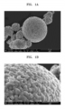
- a scanning electron microscope (Magellan 400L, manufactured by FEI company) was used. Sample sections were milled at a voltage of 6 kV and a current of 320 ⁇ A for 1 hour using IM4000PLUS (manufactured by Hitachi Corporation) to perform pretreatment. Scanning electron microscope analysis was carried at 3 keV.
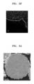
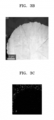
- FIGS. 1A to 1H illustrate the results of scanning electron microscope analysis.
- FIGS. 1A and 1B illustrate the state of the nickel-based active material (Li 1.01 Ni 0.8 Co 0.1 Mn 0.1 O 2 ) of Comparative Preparation Example 1 before a coating layer is formed on the surface of the nickel-based active material
- FIG. 1B is an enlarged view of a portion of FIG. 1A
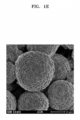
- FIGS. 1C and 1D illustrate the state of the nickel-based active material of Preparation Example 1 after a coating layer is formed on the surface of the nickel-based active material of Comparative Preparation Example 1
- FIG. 1D is an enlarged view of a portion of FIG. 1C .
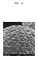
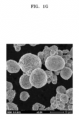
- FIGS. 1E and 1F illustrate the results of scanning electron microscope analysis of the nickel-based active material of Comparative Preparation Example 2
- FIGS. 1G and 1H illustrate the results of scanning electron microscope analysis of the nickel-based active material of Comparative Preparation Example 3.
- the composite positive electrode active material of Preparation Example 1 has a shape in which a cobalt-boron compound-containing coating layer is formed on the surface thereof.
- the state of the surface thereof is clearly different from those of the nickel-based active materials of Comparative Preparation Examples 1 to 3.
- the cobalt-boron compound-containing coating layer of the composite positive electrode active material of Preparation Example 1 has a surface having flake or cage pattern, unlike those of the nickel-based active materials of Comparative Preparation Examples 2 and 3.
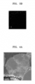
- FIGS. 2A to 2F SEM analysis and TEM-EDX mapping analysis of the composite positive electrode active material of Preparation Example 1 were carried out, and the analysis results thereof are illustrated in FIGS. 2A to 2F .
- TEM-EDX analysis was carried out using ARM300F of JEOL Corporation.
- FIG. 2A illustrates an SEM image of the composite positive electrode active material of Preparation Example 1
- FIGS. 2B to 2F illustrate the results of TEM-EDX analysis of the composite positive electrode active material of Preparation Example 1.
- Co-B compound a cobalt-boron compound
- FIGS. 2A to 2F it may be found that a cobalt-boron compound (Co-B compound) is uniformly distributed on secondary particles. Further, as illustrated in a TEM image, the Co-B compound has an amorphous phase, and has a thickness of the Co-B compound containing coating layer about 15 nm.
- a FFT scattering pattern in the inner image of FIG. 2B was observed as a circular ring, and thus the Co-B compound has an amorphous phase.
- the amorphous coating material was classified and distributed from the positive electrode active material based on dotted line. Further, as illustrated in FIG. 2F , it may found that low-intensity oxygen is attributed to synthesis condition under an inert atmosphere.
- each of the coin cells was charged with a constant current of 0.1 C until a voltage reached 4.40 V, and was then charged with a constant voltage until a current reached 0.05 C.
- the completely charged coin cell was discharged to a constant current of 0.1 C until the voltage reached 3 V after a pause of about 10 minutes.
- each of the coin cells was charged with a constant current of 0.2 C until a voltage reached 4.40 V, and was then charged with a constant voltage until a current reached 0.05 C.
- the completely charged coin cell was discharged to a constant current of 0.2 C until the voltage reached 3 V after a pause of about 10 minutes.
- each of the coin cells was charged with a constant current of 1 C until a voltage reached 4.40 V, and was then charged with a constant voltage until a current reached 0.05 C.
- the completely charged coin cell was discharged to a constant current of 1 C until the voltage reached 3 V after a pause of about 10 minutes.
- the lifetime evaluation was performed by repeating this cycle.
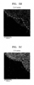
- FIGS. 3A to 3D and FIGS. 4A to 4D The states of electrode plates of positive electrodes after cycle characteristic tests were analyzed using SEM, and the results thereof are illustrated in FIGS. 3A to 3D and FIGS. 4A to 4D .
- FIG. 3A illustrates an SEM image of the positive electrode of Example 1 after a cycle characteristic test
- FIGS. 3B to 3D illustrate a TEM-EDX state of the positive electrode of Example 1 after a cycle characteristic test
- FIG. 4A illustrates an SEM image of the positive electrode of Comparative Example 1 after a cycle characteristic test
- FIGS. 4B to 4D illustrate a TEM-EDX state of the positive electrode of Comparative Example 1 after a cycle characteristic test.
- FIGS. 4A and 4B it may be found that, in the positive electrode of Comparative Example 1, cracks or micro-cracks were observed in the positive electrode active material after the cycle characteristics test.
- FIGS. 4C and 4D it may be found that fluorine and carbon were concentrated on the outermost surface of the composite positive electrode active material having a shape of secondary particles, and some of them were distributed along the micro-cracks formed in the secondary particles.
- FIGS. 4A and 4B it may be found that, in the positive electrode of Example 1, few cracks or micro-cracks appeared after the cycle characteristics test. As illustrated in FIGS. 4C and 4D , it may be found that almost no fluorine and carbon were observed, and were not distributed along inner cracks.
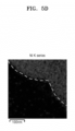
- TEM-EDX images of composite positive electrode active material particles in the positive electrode of Example 1 after the cycle characteristic test were analyzed, and the results thereof are illustrated in FIGS. 5A to 5D .
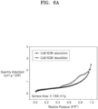
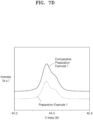
- the composite positive electrode active material of Preparation Example 1 shows a hysteresis curve in the medium-pressure area, which means that small-size mesopores having a small particle diameter are formed.
- the nickel-based active material of Comparative Preparation Example 1 showed rapid growth in the high-pressure area. From this, it may be found that the voids of the nickel-based active material of Comparative Preparation Example 1 have characteristics of macropores.
- peaks corresponding to mesopores (average pore diameter: about 10 nm) were formed larger. That is, in the composite positive electrode active material of Preparation Example 1, the amorphous cobalt-boron compound contained in the coating layer fills the inner voids between the secondary particles to reduce macropores, and thus the unit area of the composite positive electrode active material of Preparation Example 1 was greatly increased due to mesopores derived from the cobalt-boron compound itself, as compared with the unit area of the nickel-based active material of Comparative Preparation Example 1. These mesopores can act as a space for rapid lithium diffusion in the coating layer containing the cobalt-boron compound. These mesopores may act as a space for rapid lithium diffusion in the cobalt-boron compound-containing coating layer.
- each of the coin cells was charged with a constant current of 0.1 C until a voltage reached 4.40 V, and was then charged with a constant voltage until a current reached 0.05 C.
- the completely charged coin cell was discharged to a constant current of 0.1 C until the voltage reached 3 V after a pause of about 10 minutes.
- each of the coin cells was charged with a constant current of 0.2 C until a voltage reached 4.40 V, and was then charged with a constant voltage until a current reached 0.05 C.
- the completely charged coin cell was discharged to a constant current of 0.2 C until the voltage reached 3 V after a pause of about 10 minutes.
- each of the coin cells was charged with a constant current of 1 C until a voltage reached 4.40 V, and was then charged with a constant voltage until a current reached 0.05 C.
- the completely charged coin cell was discharged to a constant current of 1 C until the voltage reached 3 V after a pause of about 10 minutes.
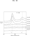
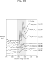
- FIGS. 8A to 8D the results of TEM-EELS analyses of the composite positive electrode active material before and after cycle characteristic test are illustrated in FIGS. 8A to 8D and FIGS. 9A to 9D .
- TEM-EELS analyses Aztec of Oxford Corporation and ARM300F of JEOL Corporation were used, respectively.
- Example 1 it may be found that before evaluating the cycle characteristics, as illustrated in FIGS. 8A to 8D , a cobalt-boron compound was present in a surface layer, and that after evaluating the cycle characteristics, as illustrated in FIGS. 9A to 9D , cobalt-boron compound remains stable in the surface layer even after high voltage cycles, and the surface composition of the nickel-based positive electrode active material remains stable without being significantly affected.
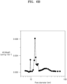
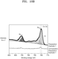
- XPS analysis was carried out. XPS analysis was performed using K-alpha x-ray photoelectron spectrometer of Thermo Fisher Corporation (Acceleration voltage: 200eV-3.0keV, double focusing hemispherical analyzer used, minimum analysis area 20micro, and X-ray irradiation area: 2mm x 2mm).
- FIGS. 10A and 10B illustrate X-ray spectroscopy analysis results of the composite positive electrode active material of Preparation Example 1 and the positive electrode active material of Comparative Preparation Example 1, respectively.
- the constituent elements of the coating layer of the composite positive electrode active material of Preparation Example 1 are boron and cobalt. Further, referring to FIG. 10B , it may be found that, based on the fact that the peak of Co 2p3/2 of XPS is shifted in the direction of low binding energy, cobalt of a general nickel-based active material has an oxidation number of +3, whereas cobalt of the cobalt-boron compound has an oxidation number of about +2 or +2+ ⁇ (- 1 ⁇ +1) lower than that of the general nickel -based active material.
- each of the coin cells was charged with a constant current of 0.1 C until a voltage reached 4.40 V, and was then charged with a constant voltage until a current reached 0.05 C.
- the completely charged coin cell was discharged to a constant current of 0.1 C until the voltage reached 3 V after a pause of about 10 minutes.
- each of the coin cells was charged with a constant current of 0.5 C until a voltage reached 4.40 V, and was then charged with a constant voltage until a current reached 0.05 C.
- the completely charged coin cell was discharged to a constant current of 1.0 C until the voltage reached 3 V after a pause of about 10 minutes.
- each of the coin cells was charged with a constant current of 1 C until a voltage reached 4.40 V, and was then charged with a constant voltage until a current reached 0.05 C.
- the completely charged coin cell was discharged to a constant current of 1 C until the voltage reached 3 V after a pause of about 10 minutes.
- CRR capacity retention rate
- the capacity retention rate characteristics were evaluated, and the results thereof are shown in Table 1 below.
- the capacity retention rate characteristics are shown in FIG. 11A .
- Capacity retention rate [%] [discharge capacity of 100 th cycle / discharge capacity of 1 st cycle] ⁇ 100 [Table 1] Class.
- Room-temperature capacity retention rate (%) Example 1 94.2 Comparative Example 1 85.2 Comparative Example 2 77.5 Comparative Example 3 83.5
- the lithium secondary battery manufactured according to Example 1 exhibits an improved capacity retention rate at room temperature (25°C) as compared with the lithium secondary batteries of Comparative Examples 1 to 3.
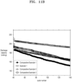
- the charge/discharge characteristics of the lithium secondary batteries manufactured according to Example 1 and Comparative Examples 1 to 3 were evaluated in the same manner as in the evaluation of the cycle characteristics of the lithium secondary batteries manufactured according to Example 1 and Comparative Examples 1 to 3, except that the evaluation was performed at high temperature (45°C) instead of at room temperature (25°C).
- Capacity retention rate (CRR) was calculated by Equation 1, and the results thereof are shown in Table 2 and FIG. 11B .
- Capacity retention rate [%] [discharge capacity of 100 th cycle / discharge capacity of 1 st cycle] ⁇ 100 [Table 2] Class.
- Capacity retention rate (%) Example 1 94.0 Comparative Example 1 85.2 Comparative Example 2 87.7 Comparative Example 3 83.9
- the lithium secondary battery manufactured according to Example 1 exhibits improved capacity retention rate at high temperature (45°C) as compared with the lithium secondary batteries of Comparative Examples 1 to 3.
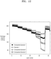
- each of the lithium secondary batteries manufactured in Example 1 and Comparative Examples 1 to 3 in the first cycle, at room temperature (25°C), each of the lithium secondary batteries was charged to 4.40 V with a constant current at a rate of 0.5 C, and was then discharged to 3 V with a constant current at a rate of 0.5 C.
- the 1st cycle was repeatedly carried out four times (2nd to 5th cycles).
- each of the lithium secondary batteries was charged to 4.40 V with a constant current at a rate of 0.5 C, charged with a constant voltage while maintaining 4.40 V until the current reached 0.05 C, and then discharged to 3 V with a constant current at a rate of 1.0 C.
- the 6th cycle was repeatedly carried out four times (7th to 10th cycles).
- each of the lithium secondary batteries was charged to 4.40 V with a constant current at a rate of 0.5 C, charged with a constant voltage while maintaining 4.40 V until the current reached 0.05 C, and then discharged to 3 V with a constant current at a rate of 2.0 C.
- the 11th cycle was repeatedly carried out four times (12th to 15th cycles).
- each of the lithium secondary batteries was charged to 4.40 V with a constant current at a rate of 0.5 C, charged with a constant voltage while maintaining 4.40 V until the current reached 0.05 C, and then discharged to 3 V with a constant current at a rate of 3.0 C.
- the 16th cycle was repeatedly carried out four times (17th to 20th cycles).
- each of the lithium secondary batteries was charged to 4.40 V with a constant current at a rate of 0.5 C, charged with a constant voltage while maintaining 4.40 V until the current reached 0.05 C, and then discharged to 3 V with a constant current at a rate of 5.0 C.
- the 21st cycle was repeatedly carried out four times (22th to 25th cycles).
- each of the lithium secondary batteries was charged to 4.40 V with a constant current at a rate of 0.5 C, charged with a constant voltage while maintaining 4.40 V until the current reached 0.05 C, and then discharged to 3 V with a constant current at a rate of 7.0 C.
- the 26th cycle was repeatedly carried out four times (27th to 30th cycles).
- each of the lithium secondary batteries was charged to 4.40 V with a constant current at a rate of 0.5 C, charged with a constant voltage while maintaining 4.40 V until the current reached 0.05 C, and then discharged to 3 V with a constant current at a rate of 10.0 C.
- the 31st cycle was repeatedly carried out four times (32th to 35th cycles).
- each of the lithium secondary batteries was charged to 4.40 V with a constant current at a rate of 0.5 C, charged with a constant voltage while maintaining 4.40 V until the current reached 0.05 C, and then discharged to 3 V with a constant current at a rate of 0.5 C.
- the 36th cycle was repeatedly carried out four times (37th to 40th cycles).
- the lithium secondary battery of Example 1 has improved room temperature rate characteristics compared to the lithium secondary battery of Comparative Example 1.
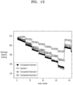
- each of the lithium secondary batteries manufactured in Example 1 and Comparative Example 1 in the first cycle, at high temperature (45°C), each of the lithium secondary batteries was charged to 4.40 V with a constant current at a rate of 0.5 C, and was then discharged to 3 V with a constant current at a rate of 0.5 C.
- the 1st cycle was repeatedly carried out four times (2nd to 5th cycles).
- each of the lithium secondary batteries was charged to 4.40 V with a constant current at a rate of 0.5 C, charged with a constant voltage while maintaining 4.40 V until the current reached 0.05 C, and then discharged to 3 V with a constant current at a rate of 1.0 C.
- the 6th cycle was repeatedly carried out four times (7th to 10th cycles).
- each of the lithium secondary batteries was charged to 4.40 V with a constant current at a rate of 0.5 C, charged with a constant voltage while maintaining 4.40 V until the current reached 0.05 C, and then discharged to 3 V with a constant current at a rate of 2.0 C.
- the 11th cycle was repeatedly carried out four times (12th to 15th cycles).
- each of the lithium secondary batteries was charged to 4.40 V with a constant current at a rate of 0.5 C, charged with a constant voltage while maintaining 4.40 V until the current reached 0.05 C, and then discharged to 3 V with a constant current at a rate of 3.0 C.
- the 16th cycle was repeatedly carried out four times (17th to 20th cycles).
- each of the lithium secondary batteries was charged to 4.40 V with a constant current at a rate of 0.5 C, charged with a constant voltage while maintaining 4.40 V until the current reached 0.05 C, and then discharged to 3 V with a constant current at a rate of 5.0 C.
- the 21st cycle was repeatedly carried out four times (22nd to 25th cycles).
- each of the lithium secondary batteries was charged to 4.40 V with a constant current at a rate of 0.5 C, charged with a constant voltage while maintaining 4.40 V until the current reached 0.05 C, and then discharged to 3 V with a constant current at a rate of 7.0 C.
- the 26th cycle was repeatedly carried out four times (27th to 30th cycles).
- each of the lithium secondary batteries was charged to 4.40 V with a constant current at a rate of 0.5 C, charged with a constant voltage while maintaining 4.40 V until the current reached 0.05 C, and then discharged to 3 V with a constant current at a rate of 10.0 C.
- the 31st cycle was repeatedly carried out four times (32th to 35th cycles).
- each of the lithium secondary batteries was charged to 4.40 V with a constant current at a rate of 0.5 C, charged with a constant voltage while maintaining 4.40 V until the current reached 0.05 C, and then discharged to 3 V with a constant current at a rate of 0.5 C.
- the 36th cycle was repeatedly carried out four times (37th to 40th cycles).
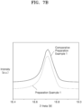
- FIG. 13 illustrates a change in high temperature rate characteristics in the lithium batteries of Example 1 and Comparative Examples 1 to 3.
- Example 1 Comparative Example 1 Comparative Example 2 Comparative Example 3 Discharge capacity (mAh/g) Discharge capacity (mAh/g) Discharge capacity (mAh/g) Discharge capacity (mAh/g) 0.5 C 216 213 213 213 1.0 C 213 201 203 204 2.0C 207 190 192 195 3.0 C 202 182 185 190 5.0 C 197 174 176 183 7.0 C 192 167 167 177 10.0 C 187 156 150 169 0.5 C 210 195 195 199 1 st cycle 206 186 187 193 100 th cycle 194 150 164 162 Capacity retention rate (%) 94.2 80.6 87.8 83.9
- the lithium secondary battery of Example 1 has improved high-temperature rate characteristics compared to the lithium secondary batteries of Comparative Examples 1 to 3.
- the positive electrode of Example 1 hardly generates cracks after evaluation of cycle characteristics as compared with the positive electrodes of Comparative Examples 1 to 3 shown in FIGS. 14B to 14D .
- a composite positive electrode active material according to an embodiment When a composite positive electrode active material according to an embodiment is used, it is possible to suppress the formation of micro-cracks occurring at a high voltage and during high-temperature cycles and improve phase stability. When this composite positive electrode active material is used, it is possible to manufacture a lithium secondary battery having improved lifetime and high-rate characteristics.
Landscapes
- Chemical & Material Sciences (AREA)
- Chemical Kinetics & Catalysis (AREA)
- Electrochemistry (AREA)
- General Chemical & Material Sciences (AREA)
- Inorganic Chemistry (AREA)
- Engineering & Computer Science (AREA)
- Organic Chemistry (AREA)
- Manufacturing & Machinery (AREA)
- Composite Materials (AREA)
- Materials Engineering (AREA)
- Battery Electrode And Active Subsutance (AREA)
- Secondary Cells (AREA)
- Inorganic Compounds Of Heavy Metals (AREA)
Applications Claiming Priority (1)
| Application Number | Priority Date | Filing Date | Title |
|---|---|---|---|
| KR1020200027983A KR102379561B1 (ko) | 2020-03-05 | 2020-03-05 | 리튬이차전지용 복합양극활물질, 그 제조방법 및 이를 포함하는 양극을 함유한 리튬이차전지 |
Publications (2)
| Publication Number | Publication Date |
|---|---|
| EP3875434A1 EP3875434A1 (en) | 2021-09-08 |
| EP3875434B1 true EP3875434B1 (en) | 2024-11-13 |
Family
ID=74859716
Family Applications (1)
| Application Number | Title | Priority Date | Filing Date |
|---|---|---|---|
| EP21161111.6A Active EP3875434B1 (en) | 2020-03-05 | 2021-03-05 | Composite positive electrode active material for lithium secondary battery, preparation method thereof, and lithium secondary battery including positive electrode including the same |
Country Status (7)
| Country | Link |
|---|---|
| US (3) | US12107268B2 (pl) |
| EP (1) | EP3875434B1 (pl) |
| JP (1) | JP7165769B2 (pl) |
| KR (1) | KR102379561B1 (pl) |
| CN (1) | CN113363472B (pl) |
| HU (1) | HUE070576T2 (pl) |
| PL (1) | PL3875434T3 (pl) |
Families Citing this family (21)
| Publication number | Priority date | Publication date | Assignee | Title |
|---|---|---|---|---|
| WO2015153485A1 (en) | 2014-04-01 | 2015-10-08 | The Research Foundation For The State University Of New York | Electrode materials for group ii cation-based batteries |
| KR102379561B1 (ko) | 2020-03-05 | 2022-03-28 | 삼성에스디아이 주식회사 | 리튬이차전지용 복합양극활물질, 그 제조방법 및 이를 포함하는 양극을 함유한 리튬이차전지 |
| CN120637475A (zh) * | 2021-09-23 | 2025-09-12 | 贵州振华新材料有限公司 | 一种锂离子电池正极材料及制法和应用 |
| KR102669346B1 (ko) * | 2021-10-01 | 2024-05-28 | 주식회사 엘지에너지솔루션 | 리튬 이차전지용 양극 활물질의 제조 방법 및 이에 의하여 제조된 양극 활물질 |
| KR102732918B1 (ko) | 2021-11-24 | 2024-11-25 | 주식회사 엘지에너지솔루션 | 리튬 이차전지용 양극 활물질의 제조 방법 및 이에 의하여 제조된 양극 활물질 |
| CN118302876A (zh) * | 2021-12-23 | 2024-07-05 | 株式会社Lg化学 | 锂二次电池用正极活性材料及其制备方法 |
| US20250038168A1 (en) * | 2021-12-23 | 2025-01-30 | LG Energy Solution, LTD | Method for Manufacturing Lithium Secondary Battery and Lithium Secondary Battery Manufactured Thereby |
| CN114267841B (zh) * | 2021-12-24 | 2023-03-21 | 广西师范大学 | 一种表面全包覆的高镍单晶三元材料的制备方法及应用 |
| CN115832231B (zh) * | 2021-12-27 | 2025-08-26 | 北京当升材料科技股份有限公司 | 正极材料及其制备方法与应用、锂离子电池 |
| CN119108552A (zh) * | 2021-12-31 | 2024-12-10 | 贵州振华新材料有限公司 | 一种锂离子电池高镍正极材料及制法和应用 |
| US20250062323A1 (en) * | 2022-01-07 | 2025-02-20 | Lg Energy Solution, Ltd. | Positive Electrode Active Material, Preparation Method Thereof, and Positive Electrode and Lithium Secondary Battery Which Include the Positive Electrode Active Material |
| CN114583102B (zh) * | 2022-02-21 | 2023-08-15 | 远景动力技术(江苏)有限公司 | 正极活性材料、电化学装置和电子设备 |
| JPWO2023162694A1 (pl) * | 2022-02-28 | 2023-08-31 | ||
| JP2025518250A (ja) * | 2022-09-30 | 2025-06-12 | エルジー エナジー ソリューション リミテッド | 正極材、正極、および二次電池 |
| EP4607612A4 (en) * | 2023-03-22 | 2026-03-04 | Contemporary Amperex Technology Hong Kong Ltd | Positive electrode active material, battery cell, battery, and electric device |
| CN116387492B (zh) * | 2023-05-04 | 2025-11-18 | 巴斯夫杉杉电池材料有限公司 | 共包覆改性正极材料、其制备方法和锂离子电池 |
| JP7483987B1 (ja) | 2023-05-31 | 2024-05-15 | 住友化学株式会社 | リチウム金属複合酸化物、リチウム二次電池用正極活物質、リチウム二次電池用正極、及び、リチウム二次電池 |
| EP4708386A1 (en) * | 2023-06-02 | 2026-03-11 | LG Chem, Ltd. | Cathode active material, preparation method therefor, and cathode and lithium secondary battery which comprise same |
| EP4708388A1 (en) * | 2023-06-02 | 2026-03-11 | LG Chem, Ltd. | Positive electrode active material, and positive electrode and lithium secondary battery comprising same |
| JP7730866B2 (ja) * | 2023-08-10 | 2025-08-28 | キヤノン株式会社 | 電極、電極複合体、二次電池、及び電極の製造方法 |
| WO2025226061A1 (ko) * | 2024-04-25 | 2025-10-30 | 톈무 레이크 인스티튜트 오브 어드밴스드 에너지 스토리지 테크놀로지 컴퍼니 리미티드 | 담금질액, 표면 안정화 처리된 리튬-리치 망간계 양극재의 제조방법 및 2차 전지 |
Family Cites Families (19)
| Publication number | Priority date | Publication date | Assignee | Title |
|---|---|---|---|---|
| KR100382305B1 (ko) | 2000-12-04 | 2003-05-09 | 삼성에스디아이 주식회사 | 리튬 이차 전지용 양극 활물질 및 그의 제조 방법 |
| KR100420034B1 (ko) | 2001-10-17 | 2004-02-25 | 삼성에스디아이 주식회사 | 리튬 이차 전지용 양극 활물질의 제조방법 |
| US20130092674A1 (en) | 2009-06-05 | 2013-04-18 | Lincoln Global, Inc. | Electrodes incorporating metallic coated particles and methods thereof |
| JP5370515B2 (ja) * | 2012-02-22 | 2013-12-18 | 住友金属鉱山株式会社 | 非水系電解質二次電池用正極材料とその製造方法、および該正極材料を用いた非水系電解質二次電池 |
| DE202013012169U1 (de) | 2012-12-10 | 2015-10-13 | Lincoln Global, Inc. | Metallisch beschichtete Teilchen enthaltende Elektroden |
| CN105722791B (zh) * | 2013-11-15 | 2018-01-26 | 住友金属矿山株式会社 | 经表面处理的氧化物粒子的制造方法及通过该方法得到的氧化物粒子 |
| JP6296156B2 (ja) | 2014-06-04 | 2018-03-20 | 株式会社豊田自動織機 | リチウム複合金属酸化物部とホウ素含有部とを有する材料及びその製造方法 |
| KR101747140B1 (ko) | 2014-08-29 | 2017-06-14 | 주식회사 엘 앤 에프 | 리튬 이차 전지용 니켈계 복합 산화물, 및 이를 포함하는 리튬 이차 전지 |
| KR102534607B1 (ko) | 2016-12-28 | 2023-05-22 | 주식회사 엘지에너지솔루션 | 리튬 이차전지용 양극활물질, 이의 제조방법, 및 이를 포함하는 리튬 이차전지 |
| WO2019074305A2 (ko) | 2017-10-12 | 2019-04-18 | 주식회사 엘지화학 | 리튬 이차전지용 양극 활물질, 이의 제조방법, 이를 포함하는 리튬 이차전지용 양극 및 리튬 이차전지 |
| KR102213174B1 (ko) | 2017-10-12 | 2021-02-05 | 주식회사 엘지화학 | 리튬 이차전지용 양극 활물질, 이의 제조방법, 이를 포함하는 리튬 이차전지용 양극 및 리튬 이차전지 |
| KR20190048923A (ko) | 2017-10-31 | 2019-05-09 | 울산과학기술원 | 이차전지용 양극활물질, 이의 제조방법 및 이를 포함하는 이차전지 |
| KR102698845B1 (ko) * | 2017-12-27 | 2024-08-26 | 주식회사 엘지에너지솔루션 | 리튬 이차 전지용 양극 활물질, 이의 제조 방법, 이를 포함하는 양극 및 리튬 이차 전지 |
| KR102288290B1 (ko) | 2018-02-23 | 2021-08-10 | 주식회사 엘지화학 | 이차전지용 양극 활물질, 그 제조방법 및 이를 포함하는 리튬 이차전지 |
| CN108550802B (zh) | 2018-03-05 | 2020-09-08 | 格林美(无锡)能源材料有限公司 | 一种Y/La掺杂Co/B共包覆的镍钴锰三元正极材料及制备方法 |
| CN110459736B (zh) | 2018-05-07 | 2021-01-12 | 宁德新能源科技有限公司 | 正极材料及含有该正极材料的正极极片和锂离子电池 |
| KR102256298B1 (ko) * | 2018-06-26 | 2021-05-26 | 삼성에스디아이 주식회사 | 리튬이차전지용 니켈계 활물질 전구체, 이의 제조방법, 이로부터 형성된 리튬이차전지용 니켈계 활물질 및 이를 포함하는 양극을 함유한 리튬이차전지 |
| KR102084689B1 (ko) | 2019-08-02 | 2020-05-29 | 울산과학기술원 | 이차전지용 양극활물질, 이의 제조방법 및 이를 포함하는 이차전지 |
| KR102379561B1 (ko) | 2020-03-05 | 2022-03-28 | 삼성에스디아이 주식회사 | 리튬이차전지용 복합양극활물질, 그 제조방법 및 이를 포함하는 양극을 함유한 리튬이차전지 |
-
2020
- 2020-03-05 KR KR1020200027983A patent/KR102379561B1/ko active Active
-
2021
- 2021-03-04 US US17/192,711 patent/US12107268B2/en active Active
- 2021-03-05 JP JP2021035263A patent/JP7165769B2/ja active Active
- 2021-03-05 EP EP21161111.6A patent/EP3875434B1/en active Active
- 2021-03-05 CN CN202110244070.1A patent/CN113363472B/zh active Active
- 2021-03-05 HU HUE21161111A patent/HUE070576T2/hu unknown
- 2021-03-05 PL PL21161111.6T patent/PL3875434T3/pl unknown
-
2023
- 2023-11-09 US US18/505,945 patent/US12308430B2/en active Active
-
2025
- 2025-04-23 US US19/187,863 patent/US20250266447A1/en active Pending
Also Published As
| Publication number | Publication date |
|---|---|
| JP2021141066A (ja) | 2021-09-16 |
| US20210280866A1 (en) | 2021-09-09 |
| US20240079585A1 (en) | 2024-03-07 |
| US12308430B2 (en) | 2025-05-20 |
| CN113363472B (zh) | 2024-08-16 |
| EP3875434A1 (en) | 2021-09-08 |
| HUE070576T2 (hu) | 2025-06-28 |
| KR102379561B1 (ko) | 2022-03-28 |
| KR20210112673A (ko) | 2021-09-15 |
| US20250266447A1 (en) | 2025-08-21 |
| JP7165769B2 (ja) | 2022-11-04 |
| CN113363472A (zh) | 2021-09-07 |
| US12107268B2 (en) | 2024-10-01 |
| PL3875434T3 (pl) | 2025-04-28 |
Similar Documents
| Publication | Publication Date | Title |
|---|---|---|
| EP3875434B1 (en) | Composite positive electrode active material for lithium secondary battery, preparation method thereof, and lithium secondary battery including positive electrode including the same | |
| US11843116B2 (en) | Nickel active material precursor for lithium secondary battery, method for producing nickel active material precursor, nickel active material for lithium secondary battery produced by method, and lithium secondary battery having cathode containing nickel active material | |
| US11837724B2 (en) | Nickel-based active material precursor for lithium secondary battery, method of preparing the same, nickel-based active material for lithium secondary battery produced from the nickel-based active material precursor, and lithium secondary battery having cathode containing the nickel-based active material | |
| US11355745B2 (en) | Nickel active material precursor for lithium secondary battery, method for producing nickel active material precursor, nickel active material for lithium secondary battery produced by method, and lithium secondary battery having cathode containing nickel active material | |
| US11201328B2 (en) | Nickel active material precursor for lithium secondary battery, method for producing nickel active material precursor, nickel active material for lithium secondary battery produced by method, and lithium secondary battery having cathode containing nickel active material | |
| EP3333129B1 (en) | Nickel-based active material for lithium secondary battery, preparing method thereof, and lithium secondary battery including positive electrode including the same | |
| EP3723172A2 (en) | Cathode active material for lithium secondary battery, manufacturing method therefor, and lithium secondary battery comprising cathode comprising same | |
| US20220388865A1 (en) | Composite cathode active material, method of preparing the same, cathode including the same, and lithium secondary battery including cathode | |
| JP2020064858A (ja) | リチウム二次電池用ニッケル系活物質前駆体、その製造方法、そこから形成されたリチウム二次電池用ニッケル系活物質、及びそれを含む正極を含んだリチウム二次電池 | |
| KR102595176B1 (ko) | 리튬이차전지용 니켈계 복합양극활물질, 그 제조방법 및 이를 포함하는 양극을 함유한 리튬이차전지 | |
| KR20180063849A (ko) | 리튬이차전지용 니켈계 활물질, 그 제조방법 및 이를 포함하는 양극을 함유한 리튬이차전지 | |
| EP4002510A1 (en) | Positive active material for rechargeable lithium battery, preparing method thereof and rechargeable lithium battery comprising positive electrode including positive active material | |
| EP3932872A2 (en) | Nickel-based lithium metal composite oxide, preparing method thereof, and lithium secondary battery including positive electrode including the same | |
| US11522189B2 (en) | Positive electrode for rechargeable lithium battery, preparing method thereof, and rechargeable lithium battery comprising positive electrode | |
| KR20180065944A (ko) | 리튬이차전지용 니켈계 활물질, 그 제조방법 및 이를 포함하는 양극을 함유한 리튬이차전지 | |
| KR20220070728A (ko) | 리튬이차전지용 양극활물질, 그 제조방법 및 이를 포함하는 양극을 포함한 리튬이차전지 | |
| JP7280330B2 (ja) | ニッケル系リチウム金属複合酸化物、その製造方法、それを含む正極、及びリチウム二次電池 | |
| KR101741027B1 (ko) | 복합체 전구체, 이로부터 형성된 복합체, 그 제조방법, 이를 포함하는 리튬 이차 전지용 양극 및 이를 구비한 리튬 이차 전지 |
Legal Events
| Date | Code | Title | Description |
|---|---|---|---|
| PUAI | Public reference made under article 153(3) epc to a published international application that has entered the european phase |
Free format text: ORIGINAL CODE: 0009012 |
|
| STAA | Information on the status of an ep patent application or granted ep patent |
Free format text: STATUS: REQUEST FOR EXAMINATION WAS MADE |
|
| 17P | Request for examination filed |
Effective date: 20210305 |
|
| AK | Designated contracting states |
Kind code of ref document: A1 Designated state(s): AL AT BE BG CH CY CZ DE DK EE ES FI FR GB GR HR HU IE IS IT LI LT LU LV MC MK MT NL NO PL PT RO RS SE SI SK SM TR |
|
| GRAP | Despatch of communication of intention to grant a patent |
Free format text: ORIGINAL CODE: EPIDOSNIGR1 |
|
| RIC1 | Information provided on ipc code assigned before grant |
Ipc: H01M 10/052 20100101ALN20240301BHEP Ipc: H01M 4/02 20060101ALN20240301BHEP Ipc: H01M 4/62 20060101ALI20240301BHEP Ipc: H01M 4/525 20100101ALI20240301BHEP Ipc: H01M 4/36 20060101ALI20240301BHEP Ipc: H01M 4/1391 20100101ALI20240301BHEP Ipc: C01G 53/00 20060101AFI20240301BHEP |
|
| STAA | Information on the status of an ep patent application or granted ep patent |
Free format text: STATUS: GRANT OF PATENT IS INTENDED |
|
| INTG | Intention to grant announced |
Effective date: 20240411 |
|
| GRAJ | Information related to disapproval of communication of intention to grant by the applicant or resumption of examination proceedings by the epo deleted |
Free format text: ORIGINAL CODE: EPIDOSDIGR1 |
|
| STAA | Information on the status of an ep patent application or granted ep patent |
Free format text: STATUS: REQUEST FOR EXAMINATION WAS MADE |
|
| GRAP | Despatch of communication of intention to grant a patent |
Free format text: ORIGINAL CODE: EPIDOSNIGR1 |
|
| STAA | Information on the status of an ep patent application or granted ep patent |
Free format text: STATUS: GRANT OF PATENT IS INTENDED |
|
| INTC | Intention to grant announced (deleted) | ||
| INTG | Intention to grant announced |
Effective date: 20240802 |
|
| RIC1 | Information provided on ipc code assigned before grant |
Ipc: H01M 10/052 20100101ALN20240729BHEP Ipc: H01M 4/02 20060101ALN20240729BHEP Ipc: H01M 4/62 20060101ALI20240729BHEP Ipc: H01M 4/525 20100101ALI20240729BHEP Ipc: H01M 4/36 20060101ALI20240729BHEP Ipc: H01M 4/1391 20100101ALI20240729BHEP Ipc: C01G 53/00 20060101AFI20240729BHEP |
|
| GRAS | Grant fee paid |
Free format text: ORIGINAL CODE: EPIDOSNIGR3 |
|
| GRAA | (expected) grant |
Free format text: ORIGINAL CODE: 0009210 |
|
| STAA | Information on the status of an ep patent application or granted ep patent |
Free format text: STATUS: THE PATENT HAS BEEN GRANTED |
|
| AK | Designated contracting states |
Kind code of ref document: B1 Designated state(s): AL AT BE BG CH CY CZ DE DK EE ES FI FR GB GR HR HU IE IS IT LI LT LU LV MC MK MT NL NO PL PT RO RS SE SI SK SM TR |
|
| REG | Reference to a national code |
Ref country code: GB Ref legal event code: FG4D |
|
| REG | Reference to a national code |
Ref country code: CH Ref legal event code: EP |
|
| REG | Reference to a national code |
Ref country code: DE Ref legal event code: R096 Ref document number: 602021021658 Country of ref document: DE |
|
| REG | Reference to a national code |
Ref country code: IE Ref legal event code: FG4D |
|
| REG | Reference to a national code |
Ref country code: SE Ref legal event code: TRGR |
|
| REG | Reference to a national code |
Ref country code: LT Ref legal event code: MG9D |
|
| REG | Reference to a national code |
Ref country code: NL Ref legal event code: MP Effective date: 20241113 |
|
| PGFP | Annual fee paid to national office [announced via postgrant information from national office to epo] |
Ref country code: SE Payment date: 20250310 Year of fee payment: 5 |
|
| PG25 | Lapsed in a contracting state [announced via postgrant information from national office to epo] |
Ref country code: PT Free format text: LAPSE BECAUSE OF FAILURE TO SUBMIT A TRANSLATION OF THE DESCRIPTION OR TO PAY THE FEE WITHIN THE PRESCRIBED TIME-LIMIT Effective date: 20250313 Ref country code: IS Free format text: LAPSE BECAUSE OF FAILURE TO SUBMIT A TRANSLATION OF THE DESCRIPTION OR TO PAY THE FEE WITHIN THE PRESCRIBED TIME-LIMIT Effective date: 20250313 Ref country code: HR Free format text: LAPSE BECAUSE OF FAILURE TO SUBMIT A TRANSLATION OF THE DESCRIPTION OR TO PAY THE FEE WITHIN THE PRESCRIBED TIME-LIMIT Effective date: 20241113 |
|
| PGFP | Annual fee paid to national office [announced via postgrant information from national office to epo] |
Ref country code: DE Payment date: 20250305 Year of fee payment: 5 |
|
| PG25 | Lapsed in a contracting state [announced via postgrant information from national office to epo] |
Ref country code: FI Free format text: LAPSE BECAUSE OF FAILURE TO SUBMIT A TRANSLATION OF THE DESCRIPTION OR TO PAY THE FEE WITHIN THE PRESCRIBED TIME-LIMIT Effective date: 20241113 Ref country code: NL Free format text: LAPSE BECAUSE OF FAILURE TO SUBMIT A TRANSLATION OF THE DESCRIPTION OR TO PAY THE FEE WITHIN THE PRESCRIBED TIME-LIMIT Effective date: 20241113 |
|
| REG | Reference to a national code |
Ref country code: AT Ref legal event code: MK05 Ref document number: 1741587 Country of ref document: AT Kind code of ref document: T Effective date: 20241113 |
|
| PG25 | Lapsed in a contracting state [announced via postgrant information from national office to epo] |
Ref country code: BG Free format text: LAPSE BECAUSE OF FAILURE TO SUBMIT A TRANSLATION OF THE DESCRIPTION OR TO PAY THE FEE WITHIN THE PRESCRIBED TIME-LIMIT Effective date: 20241113 |
|
| PG25 | Lapsed in a contracting state [announced via postgrant information from national office to epo] |
Ref country code: ES Free format text: LAPSE BECAUSE OF FAILURE TO SUBMIT A TRANSLATION OF THE DESCRIPTION OR TO PAY THE FEE WITHIN THE PRESCRIBED TIME-LIMIT Effective date: 20241113 |
|
| PG25 | Lapsed in a contracting state [announced via postgrant information from national office to epo] |
Ref country code: NO Free format text: LAPSE BECAUSE OF FAILURE TO SUBMIT A TRANSLATION OF THE DESCRIPTION OR TO PAY THE FEE WITHIN THE PRESCRIBED TIME-LIMIT Effective date: 20250213 |
|
| PG25 | Lapsed in a contracting state [announced via postgrant information from national office to epo] |
Ref country code: LV Free format text: LAPSE BECAUSE OF FAILURE TO SUBMIT A TRANSLATION OF THE DESCRIPTION OR TO PAY THE FEE WITHIN THE PRESCRIBED TIME-LIMIT Effective date: 20241113 Ref country code: GR Free format text: LAPSE BECAUSE OF FAILURE TO SUBMIT A TRANSLATION OF THE DESCRIPTION OR TO PAY THE FEE WITHIN THE PRESCRIBED TIME-LIMIT Effective date: 20250214 Ref country code: AT Free format text: LAPSE BECAUSE OF FAILURE TO SUBMIT A TRANSLATION OF THE DESCRIPTION OR TO PAY THE FEE WITHIN THE PRESCRIBED TIME-LIMIT Effective date: 20241113 |
|
| PGFP | Annual fee paid to national office [announced via postgrant information from national office to epo] |
Ref country code: FR Payment date: 20250310 Year of fee payment: 5 |
|
| PGFP | Annual fee paid to national office [announced via postgrant information from national office to epo] |
Ref country code: GB Payment date: 20250306 Year of fee payment: 5 |
|
| PG25 | Lapsed in a contracting state [announced via postgrant information from national office to epo] |
Ref country code: RS Free format text: LAPSE BECAUSE OF FAILURE TO SUBMIT A TRANSLATION OF THE DESCRIPTION OR TO PAY THE FEE WITHIN THE PRESCRIBED TIME-LIMIT Effective date: 20250213 |
|
| REG | Reference to a national code |
Ref country code: HU Ref legal event code: AG4A Ref document number: E070576 Country of ref document: HU |
|
| PG25 | Lapsed in a contracting state [announced via postgrant information from national office to epo] |
Ref country code: SM Free format text: LAPSE BECAUSE OF FAILURE TO SUBMIT A TRANSLATION OF THE DESCRIPTION OR TO PAY THE FEE WITHIN THE PRESCRIBED TIME-LIMIT Effective date: 20241113 |
|
| PGFP | Annual fee paid to national office [announced via postgrant information from national office to epo] |
Ref country code: PL Payment date: 20250303 Year of fee payment: 5 |
|
| PG25 | Lapsed in a contracting state [announced via postgrant information from national office to epo] |
Ref country code: DK Free format text: LAPSE BECAUSE OF FAILURE TO SUBMIT A TRANSLATION OF THE DESCRIPTION OR TO PAY THE FEE WITHIN THE PRESCRIBED TIME-LIMIT Effective date: 20241113 |
|
| PGFP | Annual fee paid to national office [announced via postgrant information from national office to epo] |
Ref country code: HU Payment date: 20250327 Year of fee payment: 5 |
|
| PG25 | Lapsed in a contracting state [announced via postgrant information from national office to epo] |
Ref country code: EE Free format text: LAPSE BECAUSE OF FAILURE TO SUBMIT A TRANSLATION OF THE DESCRIPTION OR TO PAY THE FEE WITHIN THE PRESCRIBED TIME-LIMIT Effective date: 20241113 |
|
| PG25 | Lapsed in a contracting state [announced via postgrant information from national office to epo] |
Ref country code: RO Free format text: LAPSE BECAUSE OF FAILURE TO SUBMIT A TRANSLATION OF THE DESCRIPTION OR TO PAY THE FEE WITHIN THE PRESCRIBED TIME-LIMIT Effective date: 20241113 |
|
| PG25 | Lapsed in a contracting state [announced via postgrant information from national office to epo] |
Ref country code: SK Free format text: LAPSE BECAUSE OF FAILURE TO SUBMIT A TRANSLATION OF THE DESCRIPTION OR TO PAY THE FEE WITHIN THE PRESCRIBED TIME-LIMIT Effective date: 20241113 |
|
| PG25 | Lapsed in a contracting state [announced via postgrant information from national office to epo] |
Ref country code: CZ Free format text: LAPSE BECAUSE OF FAILURE TO SUBMIT A TRANSLATION OF THE DESCRIPTION OR TO PAY THE FEE WITHIN THE PRESCRIBED TIME-LIMIT Effective date: 20241113 |
|
| PG25 | Lapsed in a contracting state [announced via postgrant information from national office to epo] |
Ref country code: IT Free format text: LAPSE BECAUSE OF FAILURE TO SUBMIT A TRANSLATION OF THE DESCRIPTION OR TO PAY THE FEE WITHIN THE PRESCRIBED TIME-LIMIT Effective date: 20241113 |
|
| REG | Reference to a national code |
Ref country code: DE Ref legal event code: R097 Ref document number: 602021021658 Country of ref document: DE |
|
| PLBE | No opposition filed within time limit |
Free format text: ORIGINAL CODE: 0009261 |
|
| STAA | Information on the status of an ep patent application or granted ep patent |
Free format text: STATUS: NO OPPOSITION FILED WITHIN TIME LIMIT |
|
| PG25 | Lapsed in a contracting state [announced via postgrant information from national office to epo] |
Ref country code: MC Free format text: LAPSE BECAUSE OF FAILURE TO SUBMIT A TRANSLATION OF THE DESCRIPTION OR TO PAY THE FEE WITHIN THE PRESCRIBED TIME-LIMIT Effective date: 20241113 |
|
| 26N | No opposition filed |
Effective date: 20250814 |
|
| REG | Reference to a national code |
Ref country code: CH Ref legal event code: H13 Free format text: ST27 STATUS EVENT CODE: U-0-0-H10-H13 (AS PROVIDED BY THE NATIONAL OFFICE) Effective date: 20251023 |
|
| PG25 | Lapsed in a contracting state [announced via postgrant information from national office to epo] |
Ref country code: LU Free format text: LAPSE BECAUSE OF NON-PAYMENT OF DUE FEES Effective date: 20250305 |
|
| REG | Reference to a national code |
Ref country code: BE Ref legal event code: MM Effective date: 20250331 |
|
| PG25 | Lapsed in a contracting state [announced via postgrant information from national office to epo] |
Ref country code: BE Free format text: LAPSE BECAUSE OF NON-PAYMENT OF DUE FEES Effective date: 20250331 |
|
| PG25 | Lapsed in a contracting state [announced via postgrant information from national office to epo] |
Ref country code: CH Free format text: LAPSE BECAUSE OF NON-PAYMENT OF DUE FEES Effective date: 20250331 |
|
| PG25 | Lapsed in a contracting state [announced via postgrant information from national office to epo] |
Ref country code: IE Free format text: LAPSE BECAUSE OF NON-PAYMENT OF DUE FEES Effective date: 20250305 |