EP3872332B1 - Moteur diesel de type à injection de carburant électronique - Google Patents
Moteur diesel de type à injection de carburant électronique Download PDFInfo
- Publication number
- EP3872332B1 EP3872332B1 EP19874807.1A EP19874807A EP3872332B1 EP 3872332 B1 EP3872332 B1 EP 3872332B1 EP 19874807 A EP19874807 A EP 19874807A EP 3872332 B1 EP3872332 B1 EP 3872332B1
- Authority
- EP
- European Patent Office
- Prior art keywords
- fuel
- injection
- fuel injection
- combustion chamber
- diesel engine
- Prior art date
- Legal status (The legal status is an assumption and is not a legal conclusion. Google has not performed a legal analysis and makes no representation as to the accuracy of the status listed.)
- Active
Links
- 239000000446 fuel Substances 0.000 title claims description 204
- 238000002347 injection Methods 0.000 title claims description 138
- 239000007924 injection Substances 0.000 title claims description 138
- 238000002485 combustion reaction Methods 0.000 claims description 58
- 239000007788 liquid Substances 0.000 claims description 57
- 238000009825 accumulation Methods 0.000 claims description 8
- 238000001514 detection method Methods 0.000 description 23
- XLYOFNOQVPJJNP-UHFFFAOYSA-N water Substances O XLYOFNOQVPJJNP-UHFFFAOYSA-N 0.000 description 12
- 239000000498 cooling water Substances 0.000 description 9
- 238000001816 cooling Methods 0.000 description 5
- 239000000567 combustion gas Substances 0.000 description 4
- 238000010586 diagram Methods 0.000 description 4
- 239000003502 gasoline Substances 0.000 description 4
- 239000002828 fuel tank Substances 0.000 description 3
- 239000000779 smoke Substances 0.000 description 3
- 239000011295 pitch Substances 0.000 description 2
- 230000001737 promoting effect Effects 0.000 description 2
- 230000000694 effects Effects 0.000 description 1
- 238000009434 installation Methods 0.000 description 1
- 230000035515 penetration Effects 0.000 description 1
- 239000000243 solution Substances 0.000 description 1
- 239000007921 spray Substances 0.000 description 1
- 238000011144 upstream manufacturing Methods 0.000 description 1
Images


Classifications
-
- F—MECHANICAL ENGINEERING; LIGHTING; HEATING; WEAPONS; BLASTING
- F02—COMBUSTION ENGINES; HOT-GAS OR COMBUSTION-PRODUCT ENGINE PLANTS
- F02B—INTERNAL-COMBUSTION PISTON ENGINES; COMBUSTION ENGINES IN GENERAL
- F02B19/00—Engines characterised by precombustion chambers
- F02B19/08—Engines characterised by precombustion chambers the chamber being of air-swirl type
-
- F—MECHANICAL ENGINEERING; LIGHTING; HEATING; WEAPONS; BLASTING
- F02—COMBUSTION ENGINES; HOT-GAS OR COMBUSTION-PRODUCT ENGINE PLANTS
- F02B—INTERNAL-COMBUSTION PISTON ENGINES; COMBUSTION ENGINES IN GENERAL
- F02B19/00—Engines characterised by precombustion chambers
- F02B19/14—Engines characterised by precombustion chambers with compression ignition
-
- F—MECHANICAL ENGINEERING; LIGHTING; HEATING; WEAPONS; BLASTING
- F02—COMBUSTION ENGINES; HOT-GAS OR COMBUSTION-PRODUCT ENGINE PLANTS
- F02B—INTERNAL-COMBUSTION PISTON ENGINES; COMBUSTION ENGINES IN GENERAL
- F02B19/00—Engines characterised by precombustion chambers
- F02B19/16—Chamber shapes or constructions not specific to sub-groups F02B19/02 - F02B19/10
- F02B19/18—Transfer passages between chamber and cylinder
-
- F—MECHANICAL ENGINEERING; LIGHTING; HEATING; WEAPONS; BLASTING
- F02—COMBUSTION ENGINES; HOT-GAS OR COMBUSTION-PRODUCT ENGINE PLANTS
- F02M—SUPPLYING COMBUSTION ENGINES IN GENERAL WITH COMBUSTIBLE MIXTURES OR CONSTITUENTS THEREOF
- F02M51/00—Fuel-injection apparatus characterised by being operated electrically
- F02M51/06—Injectors peculiar thereto with means directly operating the valve needle
-
- F—MECHANICAL ENGINEERING; LIGHTING; HEATING; WEAPONS; BLASTING
- F02—COMBUSTION ENGINES; HOT-GAS OR COMBUSTION-PRODUCT ENGINE PLANTS
- F02M—SUPPLYING COMBUSTION ENGINES IN GENERAL WITH COMBUSTIBLE MIXTURES OR CONSTITUENTS THEREOF
- F02M61/00—Fuel-injectors not provided for in groups F02M39/00 - F02M57/00 or F02M67/00
- F02M61/14—Arrangements of injectors with respect to engines; Mounting of injectors
-
- F—MECHANICAL ENGINEERING; LIGHTING; HEATING; WEAPONS; BLASTING
- F02—COMBUSTION ENGINES; HOT-GAS OR COMBUSTION-PRODUCT ENGINE PLANTS
- F02M—SUPPLYING COMBUSTION ENGINES IN GENERAL WITH COMBUSTIBLE MIXTURES OR CONSTITUENTS THEREOF
- F02M61/00—Fuel-injectors not provided for in groups F02M39/00 - F02M57/00 or F02M67/00
- F02M61/16—Details not provided for in, or of interest apart from, the apparatus of groups F02M61/02 - F02M61/14
- F02M61/18—Injection nozzles, e.g. having valve seats; Details of valve member seated ends, not otherwise provided for
- F02M61/1806—Injection nozzles, e.g. having valve seats; Details of valve member seated ends, not otherwise provided for characterised by the arrangement of discharge orifices, e.g. orientation or size
- F02M61/1813—Discharge orifices having different orientations with respect to valve member direction of movement, e.g. orientations being such that fuel jets emerging from discharge orifices collide with each other
-
- F—MECHANICAL ENGINEERING; LIGHTING; HEATING; WEAPONS; BLASTING
- F02—COMBUSTION ENGINES; HOT-GAS OR COMBUSTION-PRODUCT ENGINE PLANTS
- F02M—SUPPLYING COMBUSTION ENGINES IN GENERAL WITH COMBUSTIBLE MIXTURES OR CONSTITUENTS THEREOF
- F02M63/00—Other fuel-injection apparatus having pertinent characteristics not provided for in groups F02M39/00 - F02M57/00 or F02M67/00; Details, component parts, or accessories of fuel-injection apparatus, not provided for in, or of interest apart from, the apparatus of groups F02M39/00 - F02M61/00 or F02M67/00; Combination of fuel pump with other devices, e.g. lubricating oil pump
- F02M63/02—Fuel-injection apparatus having several injectors fed by a common pumping element, or having several pumping elements feeding a common injector; Fuel-injection apparatus having provisions for cutting-out pumps, pumping elements, or injectors; Fuel-injection apparatus having provisions for variably interconnecting pumping elements and injectors alternatively
- F02M63/0225—Fuel-injection apparatus having a common rail feeding several injectors ; Means for varying pressure in common rails; Pumps feeding common rails
-
- F—MECHANICAL ENGINEERING; LIGHTING; HEATING; WEAPONS; BLASTING
- F02—COMBUSTION ENGINES; HOT-GAS OR COMBUSTION-PRODUCT ENGINE PLANTS
- F02M—SUPPLYING COMBUSTION ENGINES IN GENERAL WITH COMBUSTIBLE MIXTURES OR CONSTITUENTS THEREOF
- F02M2200/00—Details of fuel-injection apparatus, not otherwise provided for
- F02M2200/40—Fuel-injection apparatus with fuel accumulators, e.g. a fuel injector having an integrated fuel accumulator
-
- F—MECHANICAL ENGINEERING; LIGHTING; HEATING; WEAPONS; BLASTING
- F02—COMBUSTION ENGINES; HOT-GAS OR COMBUSTION-PRODUCT ENGINE PLANTS
- F02M—SUPPLYING COMBUSTION ENGINES IN GENERAL WITH COMBUSTIBLE MIXTURES OR CONSTITUENTS THEREOF
- F02M45/00—Fuel-injection apparatus characterised by having a cyclic delivery of specific time/pressure or time/quantity relationship
- F02M45/02—Fuel-injection apparatus characterised by having a cyclic delivery of specific time/pressure or time/quantity relationship with each cyclic delivery being separated into two or more parts
- F02M45/04—Fuel-injection apparatus characterised by having a cyclic delivery of specific time/pressure or time/quantity relationship with each cyclic delivery being separated into two or more parts with a small initial part, e.g. initial part for partial load and initial and main part for full load
-
- Y—GENERAL TAGGING OF NEW TECHNOLOGICAL DEVELOPMENTS; GENERAL TAGGING OF CROSS-SECTIONAL TECHNOLOGIES SPANNING OVER SEVERAL SECTIONS OF THE IPC; TECHNICAL SUBJECTS COVERED BY FORMER USPC CROSS-REFERENCE ART COLLECTIONS [XRACs] AND DIGESTS
- Y02—TECHNOLOGIES OR APPLICATIONS FOR MITIGATION OR ADAPTATION AGAINST CLIMATE CHANGE
- Y02T—CLIMATE CHANGE MITIGATION TECHNOLOGIES RELATED TO TRANSPORTATION
- Y02T10/00—Road transport of goods or passengers
- Y02T10/10—Internal combustion engine [ICE] based vehicles
- Y02T10/12—Improving ICE efficiencies
Definitions
- the present invention relates to an electronic fuel injection type diesel engine, and more particularly to an electronic fuel injection type diesel engine capable of downsizing the engine.
- Patent Document 1 when a bore diameter of a cylinder is reduced, combustion deteriorates, and problems such as increases in high noise, fuel consumption, and smoke concentration occur, so that the engine cannot be miniaturized.
- An object of the present invention is to provide an electronic fuel injection type diesel engine capable of downsizing the engine.
- the present invention comprises an electronic fuel injection type diesel engine as claimed in claim 1.
- injection of the liquid fuel (5) in the fuel injection chamber (4) is electronically controlled, and combustion in the combustion chamber (2) is controlled by adjusting premixing of the liquid fuel (5) and compressed air (10) in the fuel injection chamber (4).
- a bore diameter of the cylinder (1) is reduced, noise, fuel consumption, and smoke concentration can be kept low, and the engine can be miniaturized.
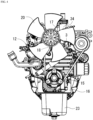
- Figs. 1(A) to 4 are diagrams for explaining an electronic fuel injection type diesel engine according to an embodiment of the present invention, and in this embodiment, a water-cooled in-line two-cylinder electronic fuel injection type diesel engine will be described.
- crankshaft shown in Fig. 3 taken as a front-rear direction and a horizontal direction orthogonal to the front-rear direction taken as a left-right direction.
- this engine includes a cylinder block (16), a cylinder head (3) mounted on the top of the cylinder block (16), a cylinder head cover (17) mounted on the top of the cylinder head (3), a water pump (18) and an oil pump (19) shown in Fig. 3 mounted on the front of the cylinder block (16), an engine cooling fan (20) mounted on the front of the water pump (18), a radiator (21) located in front of the engine cooling fan (20), a flywheel (22) located at the rear of the cylinder block (16), and an oil pan (23) mounted on the bottom of the cylinder block (16).
- This engine includes an intake device, an exhaust device, a combustion device, an electronic control unit, and an engine water cooling device.
- the intake device includes an intake manifold (24) shown in Fig. 2 and an air cleaner (not shown) connected to an intake upstream side of the intake manifold (24).
- the exhaust device includes an exhaust manifold (25) shown in Fig. 2 and an exhaust treatment unit (not shown) connected to an exhaust downstream side of the exhaust manifold (25).
- the intake manifold (24) is located on one side of left and right sides of the cylinder head (3), and the exhaust manifold (25) is located on another side of the left and right sides of the cylinder head (3).
- the combustion device includes a combustion chamber (2) inside a cylinder (1), a fuel injection chamber (4) inside the cylinder head (3), a fuel injector (6) that injects liquid fuel (5) into the fuel injection chamber (4), a fuel accumulation unit (7) that accumulates the liquid fuel (5) injected from the fuel injector (6), and an electronic control unit (8) that controls a timing and an amount of injection of the liquid fuel (5).
- injection of the liquid fuel (5) is electronically controlled, and combustion in the combustion chamber (2) is optimized by adjusting premixing of the liquid fuel (5) and compressed air (10) in the fuel injection chamber (4). Even if a bore diameter of the cylinder (1) is reduced, noise, fuel consumption, and smoke concentration can be kept low, and the engine can be miniaturized.
- An engine ECU (26) is used for the electronic control unit (8).
- ECU is an abbreviation for an electronic control unit and is a microcomputer.
- an accelerator sensor (27), a crankshaft sensor (28), and a cylinder determination sensor (29) are electrically connected to the engine ECU (26).
- the accelerator sensor (27) transmits an accelerator position detection signal to the engine ECU (26) based on detection of an operation position of an accelerator lever (not shown).
- the crankshaft sensor (28) detects actual rotation speed and a crank angle of the crankshaft (15), and transmits an actual rotation speed detection signal and a crank angle detection signal to the engine ECU (26).
- the cylinder determination sensor (29) detects a phase of a valve drive camshaft (30) shown in Fig. 2 and transmits a camshaft phase detection signal to the engine ECU (26).
- This engine is a four-cycle engine, and the valve drive camshaft (30) is a camshaft that opens and closes an intake valve (not shown) and an exhaust valve (25a).
- the engine ECU (26) has an electronic governor function. A deviation between target rotation speed and actual rotation speed of the engine is calculated based on the accelerator position detection signal and the actual rotation speed detection signal, and an engine load is calculated based on the calculation. Based on the target rotation speed of the engine and the engine load, a timing and an amount of injection of the liquid fuel (5) of the fuel injector (6) are set by a fuel control map stored in a memory. An injector control signal is transmitted to a solenoid valve (6a) of the fuel injector (6).
- the solenoid valve (6a) of the fuel injector (6) is opened for a predetermined time at a predetermined timing, and a predetermined amount of liquid fuel (5) is injected from the fuel injector (6) at a predetermined timing.
- the liquid fuel (5) is light oil.
- a potentiometer is used for the accelerator sensor (27) shown in Fig. 1(A) .
- crankshaft sensor (28).
- This crankshaft sensor (28) is a proximity sensor that detects that a protrusion of a crankshaft detection disc (not shown) attached to the flywheel (22) passes in front of the sensor.
- the crankshaft detection disc includes one starting point protrusion on the periphery and a large number of phase protrusions provided at equal pitches.
- a pickup coil is also used for the cylinder determination sensor (29).
- This cylinder determination sensor (29) is a proximity sensor that detects that a protrusion of a camshaft phase detection disc (not shown) attached to the valve drive camshaft (30) shown in Fig. 2 passes in front of the sensor.
- the camshaft phase detection disc includes one protrusion on the periphery.
- the crankshaft sensor (28) and the cylinder determination sensor (29) transmit, to the engine ECU (26), an actual rotation speed detection signal, a crank angle detection signal, and a camshaft phase detection signal by pickup signals of the protrusions.
- actual rotation speed and a crank angle of the engine are calculated from the actual rotation speed detection signal and the crank angle detection signal, and a stroke of each cylinder in a combustion cycle is determined from the camshaft phase detection signal.
- a plurality of fuel injection holes (6b) (6c) of the fuel injector (6) is provided.
- the liquid fuel (5) injected from the plurality of fuel injection holes (6b) (6c) of the fuel injector (6) is widely diffused in the fuel injection chamber (4), and premixing of the liquid fuel (5) and the compressed air (10) in the fuel injection chamber (4) is promoted.
- an injection direction of the liquid fuel (5) injected from the fuel injection hole (6c) of the fuel injector (6) is toward an inner surface of the fuel injection chamber (4).
- the liquid fuel (5) is injected from the fuel injection hole (6c) shown in Fig. 1(B) to the compressed air (10) that is pushed into the fuel injection chamber (4) from the combustion chamber (2) inside the cylinder (1) shown in Fig. 1(A) and flows along the inner surface thereof.
- the liquid fuel (5) is widely diffused into the compressed air (10), and premixing of the liquid fuel (5) and the compressed air (10) in the fuel injection chamber (4) is promoted.
- the combustion chamber (2) inside the cylinder (1) serves as a main combustion chamber (2a), and the fuel injection chamber (4) serves as a sub-combustion chamber (4a) communicated with the main combustion chamber (2a) via an injection port (9).
- liquid fuel (5) injected from the fuel injector (6) is premixed and burned with the compressed air (10) in the sub-combustion chamber (4a), and the rest is combustion gas in the premixed combustion and injected into the main combustion chamber (2a) from the injection port (9).
- the liquid fuel (5) is widely diffused in the main combustion chamber (2a), and combustion in the main combustion chamber (2a) is promoted.
- the main combustion chamber (2a) is formed between a piston (1a) and the cylinder head (3) in the cylinder (1).
- the sub-combustion chamber (4a) is formed between a recess (3a) on a bottom surface of the cylinder head (3) and a base (3b) fitted in the recess (3a), and the injection port (9) is formed on the base (3b).
- the sub-combustion chamber (4a) serves as a vortex chamber.
- the liquid fuel (5) injected from the fuel injector (6) is caught in a vortex flow of the compressed air (10) pushed into the vortex chamber from the main combustion chamber (2a), and premixing of the liquid fuel (5) and the compressed air (10) in the sub-combustion chamber (4a) is promoted.
- a direction orthogonal to an injection port central axis (9a) is taken as a lateral direction, and an opening end (9b) on the sub-combustion chamber (4a) side of the injection port (9) is formed by a laterally long hole.
- the compressed air (10) flowing into the sub-combustion chamber (4a) from the injection port (9) easily flows into a lateral space of the sub-combustion chamber (4a) through the laterally long opening end (9b), a flow of air in the lateral space is promoted, and an air utilization rate in the sub-combustion chamber (4a) increases.
- width of an opening end (9c) on the main combustion chamber (2a) side of the injection port (9) is formed longer than width of the opening end (9b) on the sub-combustion chamber (4a) side.
- combustion gas containing unburned fuel ejected from the injection port (9) into the main combustion chamber (2a) is widely ejected into the main combustion chamber (2a) through the wide opening end (9c), and an air utilization rate in the main combustion chamber (2a) increases.
- the injection port (9) has an expanded shape with a cross-sectional area expanding toward the main combustion chamber (2a).
- the combustion gas containing unburned fuel ejected from the injection port (9) into the main combustion chamber (2a) is widely diffused into the main combustion chamber (2a) through the injection port (9) having the expanded shape, and the air utilization rate in the main combustion chamber (2a) increases.
- the plurality of fuel injection holes (6b) (6c) includes the single fuel injection hole (6b) in the center in the left-right direction and the pair of fuel injection holes (6c) (6c) disposed on the left and right sides thereof.
- the left and right fuel injection holes (6c) (6c) have smaller hole diameters than the central fuel injection hole (6b), and an injection pattern of the liquid fuel (5) injected from the left and right fuel injection holes (6c) (6c) is a finer spray with smaller oil droplets than that from the central fuel injection hole (6b).
- Injection directions of the liquid fuel (5) from the left and right fuel injection holes (6c) (6c) are toward an inner surface of the sub-combustion chamber (4a) located on the left and right of the injection port (9).
- An injection direction of the liquid fuel (5) from the fuel injection hole (6b) is toward the main combustion chamber (2a) via the injection port (9).
- the injection port (9) may be composed of a central injection port (not shown) in the left-right direction and a pair of injection ports disposed on the left and right thereof.
- Injection pressure of the liquid fuel (5) from the fuel injector (6) is set to 5 to 50 MPa (megapascal).
- the injection pressure of the liquid fuel (5) from this fuel injector (6) is set quite low, while it generally sets to 120 to 160 MPa for an existing common rail type diesel engine that injects fuel directly into a combustion chamber inside a cylinder.
- the injection pressure of the liquid fuel (5) from the fuel injector (6) is only 5 to 50 MPa, and despite being the diesel engine, parts of the fuel injector (6) and fuel accumulation unit (7) of a low-pressure fuel injection gasoline injection system or the like can be diverted, and the parts can be shared with other low-pressure fuel injection systems.
- the fuel accumulation unit (7) includes an accumulator (11) and a fuel feed pump (12) that supplies the accumulator (11) with the liquid fuel (5).
- the injection pressure of the liquid fuel (5) from the fuel injector (6) is only 5 to 50 MPa, and despite being the diesel engine, the accumulator (11) and the fuel feed pump (12) of the low-pressure fuel injection gasoline injection system or the like can be diverted as they are, and the parts of the fuel accumulation unit (7) can be shared with the other low-pressure fuel injection systems.
- the accumulator (11) is a delivery pipe (11a) that distributes the liquid fuel (5) to the plurality of fuel injectors (6).
- fuel pressure in the delivery pipe (11a) is about 5 to 50 MPa, and despite being the diesel engine, the delivery pipe (11a) of the low-pressure fuel injection gasoline injection system or the like can be diverted as it is, and the part of the fuel accumulation unit (7) can be shared with other multi-cylinder low-pressure fuel injection systems.
- the delivery pipe (11a) includes a fuel pressure sensor (11b), and the fuel pressure in the delivery pipe (11a) detected by the fuel pressure sensor (11b) is sent to the engine ECU (26) as a fuel pressure detection signal.
- a pump control signal is sent from the engine ECU (26) to an electric actuator (not shown) of the fuel feed pump (12), an amount of liquid fuel (5) supplied to the delivery pipe (11a) is controlled by controlling rotation speed of the fuel feed pump (12), and the fuel pressure in the delivery pipe (11a) is adjusted.
- the fuel feed pump (12) is pumped by a pump drive cam driven by the electric actuator.
- a reference numeral (13) in Fig. 1(A) indicates a safety valve, and when the fuel pressure in the delivery pipe (11a) exceeds a predetermined upper limit, the valve is opened to decrease the fuel pressure in the delivery pipe (11a) .
- a system for adjusting the fuel pressure in the delivery pipe (11a) there may be a system in which an electric spill valve (not shown) for leaking the liquid fuel in the delivery pipe (11a) to a fuel tank (35) side is provided, the fuel pressure in the delivery pipe (11a) detected by the fuel pressure sensor (11b) is sent to the engine ECU (26) as a fuel pressure detection signal, a valve control signal is sent from the engine ECU (26) to an actuator of the electric spill valve, and an amount of leakage of the liquid fuel (5) from the delivery pipe (11a) is controlled by controlling an opening degree of the electric spill valve.
- the fuel feed pump (12), the delivery pipe (11a), and the fuel injector (6) of the existing gasoline injection system are diverted as they are.
- the fuel is supplied to the fuel feed pump (12) from the fuel tank (35), and a part of the liquid fuel (5) of the fuel feed pump (12) or the fuel injector (6) overflows and returns to the fuel tank (35) via a fuel return passage (36), thereby eliminating air pools in the fuel feed pump (12) and the fuel injector (6).
- the injection pressure of the liquid fuel (5) from the fuel injector (6) is set to 5 to 50 MPa from the viewpoint of promoting premixing of the liquid fuel (5) and the compressed air (10) in the fuel injection chamber (4), but it is more desirable to set this injection pressure to 10 to 40 MPa. This is because a function of promoting premixing can be obtained more reliably.
- Injection of the liquid fuel (5) from the fuel injector (6) includes main injection and pre-injection prior to the main injection.
- the liquid fuel (5) in the pre-injection is mixed and burned with the compressed air (10) in the fuel injection chamber (4), and the liquid fuel (5) in the main injection is ignited by combustion gas in the pre-injection, so that combustion of the liquid fuel (5) and the compressed air (10) in the fuel injection chamber (4) is promoted.
- the engine water cooling device includes the radiator (21) that radiates heat from engine cooling water, the water pump (18) that sucks the engine cooling water with the heat radiated by the radiator (21) and pumps it to a cylinder jacket, the cylinder jacket (31), a cylinder head jacket (32) in Fig. 2 that communicates with the cylinder jacket (31), a water flange (34) with a built-in thermostat valve (33) that controls return of the engine cooling water from the cylinder head jacket (32) to the radiator (21) and its stop, and a return pipe (not shown) that returns the engine cooling water in the cylinder head jacket (32) to the water pump (18) from the water flange (34).
- the thermostat valve (33) is closed so that an entire amount of the engine cooling water is sucked from the return pipe into the water pump (18), and is circulated between the cylinder jacket (31) and the cylinder head jacket (32) while bypassing the radiator (21) to warm up the engine.
- the thermostat valve (33) When the temperature of the engine cooling water rises, the thermostat valve (33) is opened, the engine cooling water is circulated between the radiator (21), the water pump (18), the cylinder jacket (31), and the cylinder head jacket (32) in that order to cool the engine. A part of the engine cooling water is sucked into the water pump (18) from the return pipe and bypasses the radiator (21).
- the present invention can also be applied to a single-cylinder engine or a multi-cylinder engine having three or more cylinders.
- calculation of the actual rotation speed and the crank angle of the engine and determination of the stroke of each cylinder in the combustion cycle are based on detection by two sensors including the crankshaft sensor (28) and the cylinder determination sensor (29).
- the calculation of the actual rotation speed and the crank angle of the engine and the determination of the stroke of each cylinder in the combustion cycle can also be performed based on detection by one phase sensor (not shown).
- a pickup coil is used for this phase sensor.
- This phase sensor is a proximity sensor that detects that a protrusion of a phase detection disc (not shown) attached to the valve drive camshaft (30) passes in front of the sensor.
- the phase detection sensor includes one starting point protrusion on the periphery and a large number of phase protrusions provided at equal pitches. This phase sensor transmits a pickup signal of the protrusion to the engine ECU (26).
- the engine ECU (26) the actual rotation speed and the crank angle of the engine are calculated based on a period of a pulse wave of the pickup signal and an ordinal number of the pulse wave of the protrusion passing in front of the sensor, and the stroke of each cylinder in the combustion cycle is determined by a phase of the pulse wave of the protrusion passing in front of the sensor.
- a low-pressure fuel injection pump for a sub-chamber type combustion chamber of a mechanical cam fuel injection type diesel engine can be diverted as the fuel feed pump (12).
- the part can be shared with the mechanical cam fuel injection type diesel engine.
- This fuel feed pump (12) is driven by the existing fuel injection camshaft (14).
Landscapes
- Engineering & Computer Science (AREA)
- Chemical & Material Sciences (AREA)
- Combustion & Propulsion (AREA)
- Mechanical Engineering (AREA)
- General Engineering & Computer Science (AREA)
- Fuel-Injection Apparatus (AREA)
Claims (8)
- Moteur Diesel du type à injection électronique de carburant, comprenant :une chambre de combustion (2) à l'intérieur d'un cylindre (1) ;une chambre d'injection de carburant (4) à l'intérieur d'une culasse (3) ;un injecteur de carburant (6) injectant un carburant liquide (5) dans la chambre d'injection de carburant (4) ;une unité d'accumulation de carburant (7) assurant l'accumulation du carburant liquide (5) injecté par l'injecteur (6) ; etun régulateur électronique (8) réglant une temporisation et un volume d'injection de carburant liquide (5),la chambre de combustion (2) à l'intérieur du cylindre (1) servant de chambre de combustion principale (2a), et la chambre d'injection de carburant (4) servant de chambre de turbulence en communication avec la chambre de combustion principale (2a) par le biais d'un orifice d'injection (9),l'orifice d'injection (9) introduisant de l'air comprimé (10) qui devient un écoulement rotationnel tourbillonnant dans la chambre de turbulence de la chambre de combustion principale (2a) à la chambre de turbulence ; etl'injecteur de carburant (6) comprenant une pluralité d'orifices d'injection de carburant (6b) (6c),caractérisé en ce quelorsqu'elle est vue d'une direction parallèle à un axe central du cylindre (1b), une direction perpendiculaire à un axe central de l'orifice d'injection (9a) est considérée comme une direction latérale, la pluralité d'orifices d'injection de carburant (6b) (6c) comprenant un orifice d'injection de carburant unique (6b) dans un centre et une paire d'orifices d'injection de carburant (6b) (6c) disposés des deux côtés de celui-ci dans la direction latérale, une injection de carburant liquide (5) provenant de l'orifice d'injection de carburant unique (6b) étant dirigée vers la chambre de combustion principale (2a) via un intérieur d'un centre de la chambre de turbulence, et un intérieur de l'orifice d'injection (9), les directions d'injection du carburant liquide (5) depuis la paire d'orifices d'injection de carburant (6c) (6c) étant vers une surface intérieure des deux côtés dans la direction latérale de la chambre de turbulence située sur les deux côtés dans la direction latérale de l'orifice d'injection (9), et le diamètre de la paire d'orifices d'injection de carburant (6b) (6c) étant inférieur à celui de l'orifice d'injection de carburant unique (6b).
- Moteur Diesel du type à injection électronique de carburant selon la revendication 1, dans lequel, lorsqu'elle est vue dans une direction parallèle à un axe central du cylindre (1c), une direction perpendiculaire à un axe central de l'orifice d'injection (9a) est une direction latérale, et une extrémité d'ouverture (9b) sur un côté de chambre de turbulence de l'orifice d'injection (9) étant formée par un orifice latéralement long.
- Moteur Diesel du type à injection électronique de carburant selon la revendication 2, la largeur latérale d'une extrémité d'ouverture (9c) sur un côté de la chambre de combustion principale (2a) de l'orifice d'injection (9) étant réalisée plus longue que la largeur latérale de l'extrémité d'ouverture (9b) sur le côté de chambre de turbulence.
- Moteur Diesel du type à injection électronique de carburant selon une quelconque des revendications 1 à 3, l'orifice d'injection (9) ayant une forme expansée avec une surface transversale s'étendant vers la chambre de combustion principale (2a).
- Moteur Diesel du type à injection électronique de carburant selon une quelconque des revendications 1 à 4, la pression d'injection du carburant liquide (5) depuis l'injecteur de carburant (6) étant réglée de 5 à 50 MPa.
- Moteur Diesel du type à injection électronique de carburant selon la revendication 5, l'unité d'accumulation de carburant (7) comprenant un accumulateur (11) et une pompe d'alimentation en carburant (12) introduisant le carburant liquide (5) dans l'accumulateur (11).
- Moteur Diesel du type à injection électronique de carburant selon la revendication 6, l'accumulateur (11) étant un tuyau (11a) distribuant le carburant liquide (5) dans plusieurs injecteurs de carburant (6).
- Moteur Diesel du type à injection électronique de carburant selon une quelconque des revendications 1 à 7, l'injection du carburant liquide (5) provenant de l'injecteur de carburant (6) comprenant l'injection principale et la pré-injection préalable à l'injection principale.
Applications Claiming Priority (2)
| Application Number | Priority Date | Filing Date | Title |
|---|---|---|---|
| JP2018201842A JP7079182B2 (ja) | 2018-10-26 | 2018-10-26 | 電子燃料噴射式ディーゼルエンジン |
| PCT/JP2019/035303 WO2020084933A1 (fr) | 2018-10-26 | 2019-09-09 | Moteur diesel de type à injection de carburant électronique |
Publications (3)
| Publication Number | Publication Date |
|---|---|
| EP3872332A1 EP3872332A1 (fr) | 2021-09-01 |
| EP3872332A4 EP3872332A4 (fr) | 2022-08-03 |
| EP3872332B1 true EP3872332B1 (fr) | 2023-10-18 |
Family
ID=70332207
Family Applications (1)
| Application Number | Title | Priority Date | Filing Date |
|---|---|---|---|
| EP19874807.1A Active EP3872332B1 (fr) | 2018-10-26 | 2019-09-09 | Moteur diesel de type à injection de carburant électronique |
Country Status (6)
| Country | Link |
|---|---|
| US (1) | US11378001B2 (fr) |
| EP (1) | EP3872332B1 (fr) |
| JP (1) | JP7079182B2 (fr) |
| KR (1) | KR20210077666A (fr) |
| CN (1) | CN112789405B (fr) |
| WO (1) | WO2020084933A1 (fr) |
Families Citing this family (1)
| Publication number | Priority date | Publication date | Assignee | Title |
|---|---|---|---|---|
| JP7348891B2 (ja) | 2020-12-28 | 2023-09-21 | 株式会社クボタ | 電子燃料噴射式ディーゼルエンジン |
Family Cites Families (29)
| Publication number | Priority date | Publication date | Assignee | Title |
|---|---|---|---|---|
| FR1436612A (fr) * | 1965-02-08 | 1966-04-29 | Applic Tech | Perfectionnements aux moteurs à combustion interne du type à chambre thermiquement isolée |
| DE2634470C3 (de) * | 1976-07-31 | 1979-06-28 | Motoren-Werke Mannheim Ag Vorm. Benz Abt. Stat. Motorenbau, 6800 Mannheim | Selbstzündende luftverdichtende Brennkraftmaschine |
| US4294208A (en) * | 1980-03-31 | 1981-10-13 | Rockwell International Corporation | Atomizing shock wave precombustor |
| JPS57183517A (en) * | 1981-05-06 | 1982-11-11 | Nissan Motor Co Ltd | Combustion chamber for diesel engine with swirl chamber |
| JPS5851215A (ja) * | 1981-09-22 | 1983-03-25 | Mitsubishi Heavy Ind Ltd | 渦流室式デイ−ゼルエンジンの燃焼室 |
| JPS59120533A (ja) | 1982-12-27 | 1984-07-12 | Mazda Motor Corp | 自動車の補助シ−ト |
| JPS59221419A (ja) * | 1983-05-30 | 1984-12-13 | Isuzu Motors Ltd | 渦流燃焼室式デイ−ゼル機関 |
| JPS6136125U (ja) * | 1984-08-03 | 1986-03-06 | マツダ株式会社 | 渦流室式デイ−ゼルエンジンの燃料噴射装置 |
| JPH0643806B2 (ja) * | 1986-05-23 | 1994-06-08 | 株式会社クボタ | デイ−ゼルエンジンのうず室式燃焼室 |
| JP2596430B2 (ja) * | 1987-10-15 | 1997-04-02 | 株式会社クボタ | 渦室式デイーゼルエンジンのピストン |
| FR2623854B1 (fr) * | 1987-11-27 | 1992-11-27 | Inst Francais Du Petrole | Dispositif d'injection pneumatique de carburant dans un cylindre d'un moteur a combustion interne |
| JPH0633816A (ja) * | 1992-07-10 | 1994-02-08 | Mazda Motor Corp | 副室式ディーゼルエンジンの燃料噴射装置 |
| JPH0614440U (ja) * | 1992-07-29 | 1994-02-25 | いすゞ自動車株式会社 | 副室式エンジンにおける副燃焼室の構造 |
| US5307772A (en) * | 1992-12-16 | 1994-05-03 | Ford Motor Company | Redox catalysis of NOx in internal combustion engines |
| JPH06193450A (ja) * | 1992-12-25 | 1994-07-12 | Yamaha Motor Co Ltd | 2サイクルエンジンの排気制御弁装置 |
| JP3293217B2 (ja) * | 1993-01-25 | 2002-06-17 | いすゞ自動車株式会社 | 副室式エンジン |
| JP3406119B2 (ja) * | 1995-06-05 | 2003-05-12 | ヤマハ発動機株式会社 | うず室式副燃焼室付き2サイクルディーゼルエンジン |
| JPH114914A (ja) | 1997-06-13 | 1999-01-12 | Maguregaa Golf Japan Kk | ゴルフボール |
| JP3822969B2 (ja) * | 1997-12-15 | 2006-09-20 | 株式会社クボタ | ディーゼルエンジンの燃料噴射装置 |
| US7389752B2 (en) * | 2005-07-12 | 2008-06-24 | Southwest Research Institute | Use of engine lubricant as ignition fuel for micro-pilot ignition system of an internal combustion engine |
| DK2239451T3 (da) * | 2009-03-30 | 2011-10-10 | Waertsilae Switzerland Ltd | Brændstofindsprøjtningsindretning til interne forbrændingsmotorer |
| ES2387372B1 (es) * | 2010-02-01 | 2013-07-29 | Jesus Manuel Diaz Escaño | Motor de combustion interna que utiliza para su funcionamiento combustibles alternativos |
| JP6136125B2 (ja) | 2012-06-21 | 2017-05-31 | 凸版印刷株式会社 | カップ型紙容器 |
| JP6032797B2 (ja) | 2012-07-18 | 2016-11-30 | 日野自動車株式会社 | 内燃機関 |
| JP6014440B2 (ja) | 2012-09-26 | 2016-10-25 | 日立オートモティブシステムズ株式会社 | 移動物体認識装置 |
| CN202954878U (zh) * | 2012-11-07 | 2013-05-29 | 镇江恒驰科技有限公司 | 一种柴油-双燃料发动机预燃室点火装置 |
| FI124730B (en) * | 2013-01-22 | 2014-12-31 | Wärtsilä Finland Oy | Method of operating a piston motor and piston motor |
| US9429066B2 (en) * | 2013-07-30 | 2016-08-30 | Kubota Corporation | Subchamber type combustion chamber for diesel engine |
| JP6384458B2 (ja) * | 2015-11-23 | 2018-09-05 | 株式会社デンソー | 燃焼システム制御装置 |
-
2018
- 2018-10-26 JP JP2018201842A patent/JP7079182B2/ja active Active
-
2019
- 2019-09-09 WO PCT/JP2019/035303 patent/WO2020084933A1/fr unknown
- 2019-09-09 CN CN201980065174.7A patent/CN112789405B/zh active Active
- 2019-09-09 KR KR1020217007701A patent/KR20210077666A/ko not_active Application Discontinuation
- 2019-09-09 US US17/282,904 patent/US11378001B2/en active Active
- 2019-09-09 EP EP19874807.1A patent/EP3872332B1/fr active Active
Also Published As
| Publication number | Publication date |
|---|---|
| US11378001B2 (en) | 2022-07-05 |
| JP2020067065A (ja) | 2020-04-30 |
| WO2020084933A1 (fr) | 2020-04-30 |
| JP7079182B2 (ja) | 2022-06-01 |
| EP3872332A4 (fr) | 2022-08-03 |
| US20210388754A1 (en) | 2021-12-16 |
| CN112789405A (zh) | 2021-05-11 |
| EP3872332A1 (fr) | 2021-09-01 |
| KR20210077666A (ko) | 2021-06-25 |
| CN112789405B (zh) | 2023-02-28 |
Similar Documents
| Publication | Publication Date | Title |
|---|---|---|
| EP1770272B1 (fr) | Moteur à combustion interne multicylindres | |
| US20120298071A1 (en) | Combustion system for internal combustion engine | |
| EP1770273B1 (fr) | Moteur multicylindre | |
| JP4541257B2 (ja) | 火花点火式エンジン | |
| US20160169145A1 (en) | Methods and systems for high pressure port fuel injection | |
| CN101194093A (zh) | 用于内燃机的控制设备 | |
| CN104141542A (zh) | 用于操作直接喷射燃料泵的系统和方法 | |
| EP1865193B1 (fr) | Dispositif d'injection de carburant pour un moteur à combustion interne | |
| JP7068157B2 (ja) | ディーゼルエンジン | |
| EP3872332B1 (fr) | Moteur diesel de type à injection de carburant électronique | |
| JP7075336B2 (ja) | ディーゼルエンジン | |
| JP2006138313A (ja) | 流量の調整装置を備えた、燃料噴射システムのための高圧ポンプ | |
| EP1691057B1 (fr) | Moteur à allumage commandé | |
| JP7144359B2 (ja) | ディーゼルエンジン | |
| EP2497920A2 (fr) | Moteur à combustion interne | |
| JP2007262996A (ja) | 内燃機関用燃料噴射装置 | |
| JP7068159B2 (ja) | ディーゼルエンジン | |
| JP7068158B2 (ja) | ディーゼルエンジン | |
| JP7144360B2 (ja) | ディーゼルエンジン | |
| JP5018374B2 (ja) | 内燃機関の燃料噴射システム | |
| JPH11351043A (ja) | 内燃機関の燃料噴射制御装置 | |
| JP2797878B2 (ja) | エマルジョン燃料エンジン | |
| Goering et al. | Diesel Engines |
Legal Events
| Date | Code | Title | Description |
|---|---|---|---|
| STAA | Information on the status of an ep patent application or granted ep patent |
Free format text: STATUS: THE INTERNATIONAL PUBLICATION HAS BEEN MADE |
|
| PUAI | Public reference made under article 153(3) epc to a published international application that has entered the european phase |
Free format text: ORIGINAL CODE: 0009012 |
|
| STAA | Information on the status of an ep patent application or granted ep patent |
Free format text: STATUS: REQUEST FOR EXAMINATION WAS MADE |
|
| 17P | Request for examination filed |
Effective date: 20210326 |
|
| AK | Designated contracting states |
Kind code of ref document: A1 Designated state(s): AL AT BE BG CH CY CZ DE DK EE ES FI FR GB GR HR HU IE IS IT LI LT LU LV MC MK MT NL NO PL PT RO RS SE SI SK SM TR |
|
| DAV | Request for validation of the european patent (deleted) | ||
| DAX | Request for extension of the european patent (deleted) | ||
| REG | Reference to a national code |
Ref document number: 602019039822 Country of ref document: DE Ref country code: DE Ref legal event code: R079 Free format text: PREVIOUS MAIN CLASS: F02M0061180000 Ipc: F02B0019080000 |
|
| A4 | Supplementary search report drawn up and despatched |
Effective date: 20220706 |
|
| RIC1 | Information provided on ipc code assigned before grant |
Ipc: F02M 63/02 20060101ALI20220630BHEP Ipc: F02M 61/18 20060101ALI20220630BHEP Ipc: F02M 61/14 20060101ALI20220630BHEP Ipc: F02M 51/06 20060101ALI20220630BHEP Ipc: F02M 51/00 20060101ALI20220630BHEP Ipc: F02M 45/04 20060101ALI20220630BHEP Ipc: F02B 19/18 20060101ALI20220630BHEP Ipc: F02B 19/14 20060101ALI20220630BHEP Ipc: F02B 19/08 20060101AFI20220630BHEP |
|
| GRAP | Despatch of communication of intention to grant a patent |
Free format text: ORIGINAL CODE: EPIDOSNIGR1 |
|
| STAA | Information on the status of an ep patent application or granted ep patent |
Free format text: STATUS: GRANT OF PATENT IS INTENDED |
|
| INTG | Intention to grant announced |
Effective date: 20230704 |
|
| GRAS | Grant fee paid |
Free format text: ORIGINAL CODE: EPIDOSNIGR3 |
|
| GRAA | (expected) grant |
Free format text: ORIGINAL CODE: 0009210 |
|
| STAA | Information on the status of an ep patent application or granted ep patent |
Free format text: STATUS: THE PATENT HAS BEEN GRANTED |
|
| AK | Designated contracting states |
Kind code of ref document: B1 Designated state(s): AL AT BE BG CH CY CZ DE DK EE ES FI FR GB GR HR HU IE IS IT LI LT LU LV MC MK MT NL NO PL PT RO RS SE SI SK SM TR |
|
| REG | Reference to a national code |
Ref country code: GB Ref legal event code: FG4D |
|
| REG | Reference to a national code |
Ref country code: CH Ref legal event code: EP |
|
| REG | Reference to a national code |
Ref country code: DE Ref legal event code: R096 Ref document number: 602019039822 Country of ref document: DE |
|
| REG | Reference to a national code |
Ref country code: IE Ref legal event code: FG4D |
|
| REG | Reference to a national code |
Ref country code: LT Ref legal event code: MG9D |
|
| REG | Reference to a national code |
Ref country code: NL Ref legal event code: MP Effective date: 20231018 |
|
| REG | Reference to a national code |
Ref country code: AT Ref legal event code: MK05 Ref document number: 1622670 Country of ref document: AT Kind code of ref document: T Effective date: 20231018 |
|
| PG25 | Lapsed in a contracting state [announced via postgrant information from national office to epo] |
Ref country code: NL Free format text: LAPSE BECAUSE OF FAILURE TO SUBMIT A TRANSLATION OF THE DESCRIPTION OR TO PAY THE FEE WITHIN THE PRESCRIBED TIME-LIMIT Effective date: 20231018 |
|
| PG25 | Lapsed in a contracting state [announced via postgrant information from national office to epo] |
Ref country code: GR Free format text: LAPSE BECAUSE OF FAILURE TO SUBMIT A TRANSLATION OF THE DESCRIPTION OR TO PAY THE FEE WITHIN THE PRESCRIBED TIME-LIMIT Effective date: 20240119 |
|
| PG25 | Lapsed in a contracting state [announced via postgrant information from national office to epo] |
Ref country code: IS Free format text: LAPSE BECAUSE OF FAILURE TO SUBMIT A TRANSLATION OF THE DESCRIPTION OR TO PAY THE FEE WITHIN THE PRESCRIBED TIME-LIMIT Effective date: 20240218 |
|
| PG25 | Lapsed in a contracting state [announced via postgrant information from national office to epo] |
Ref country code: LT Free format text: LAPSE BECAUSE OF FAILURE TO SUBMIT A TRANSLATION OF THE DESCRIPTION OR TO PAY THE FEE WITHIN THE PRESCRIBED TIME-LIMIT Effective date: 20231018 |
|
| PG25 | Lapsed in a contracting state [announced via postgrant information from national office to epo] |
Ref country code: AT Free format text: LAPSE BECAUSE OF FAILURE TO SUBMIT A TRANSLATION OF THE DESCRIPTION OR TO PAY THE FEE WITHIN THE PRESCRIBED TIME-LIMIT Effective date: 20231018 |
|
| PG25 | Lapsed in a contracting state [announced via postgrant information from national office to epo] |
Ref country code: ES Free format text: LAPSE BECAUSE OF FAILURE TO SUBMIT A TRANSLATION OF THE DESCRIPTION OR TO PAY THE FEE WITHIN THE PRESCRIBED TIME-LIMIT Effective date: 20231018 |
|
| PG25 | Lapsed in a contracting state [announced via postgrant information from national office to epo] |
Ref country code: LT Free format text: LAPSE BECAUSE OF FAILURE TO SUBMIT A TRANSLATION OF THE DESCRIPTION OR TO PAY THE FEE WITHIN THE PRESCRIBED TIME-LIMIT Effective date: 20231018 Ref country code: IS Free format text: LAPSE BECAUSE OF FAILURE TO SUBMIT A TRANSLATION OF THE DESCRIPTION OR TO PAY THE FEE WITHIN THE PRESCRIBED TIME-LIMIT Effective date: 20240218 Ref country code: GR Free format text: LAPSE BECAUSE OF FAILURE TO SUBMIT A TRANSLATION OF THE DESCRIPTION OR TO PAY THE FEE WITHIN THE PRESCRIBED TIME-LIMIT Effective date: 20240119 Ref country code: ES Free format text: LAPSE BECAUSE OF FAILURE TO SUBMIT A TRANSLATION OF THE DESCRIPTION OR TO PAY THE FEE WITHIN THE PRESCRIBED TIME-LIMIT Effective date: 20231018 Ref country code: BG Free format text: LAPSE BECAUSE OF FAILURE TO SUBMIT A TRANSLATION OF THE DESCRIPTION OR TO PAY THE FEE WITHIN THE PRESCRIBED TIME-LIMIT Effective date: 20240118 Ref country code: AT Free format text: LAPSE BECAUSE OF FAILURE TO SUBMIT A TRANSLATION OF THE DESCRIPTION OR TO PAY THE FEE WITHIN THE PRESCRIBED TIME-LIMIT Effective date: 20231018 Ref country code: PT Free format text: LAPSE BECAUSE OF FAILURE TO SUBMIT A TRANSLATION OF THE DESCRIPTION OR TO PAY THE FEE WITHIN THE PRESCRIBED TIME-LIMIT Effective date: 20240219 |
|
| PG25 | Lapsed in a contracting state [announced via postgrant information from national office to epo] |
Ref country code: SE Free format text: LAPSE BECAUSE OF FAILURE TO SUBMIT A TRANSLATION OF THE DESCRIPTION OR TO PAY THE FEE WITHIN THE PRESCRIBED TIME-LIMIT Effective date: 20231018 Ref country code: RS Free format text: LAPSE BECAUSE OF FAILURE TO SUBMIT A TRANSLATION OF THE DESCRIPTION OR TO PAY THE FEE WITHIN THE PRESCRIBED TIME-LIMIT Effective date: 20231018 Ref country code: PL Free format text: LAPSE BECAUSE OF FAILURE TO SUBMIT A TRANSLATION OF THE DESCRIPTION OR TO PAY THE FEE WITHIN THE PRESCRIBED TIME-LIMIT Effective date: 20231018 Ref country code: NO Free format text: LAPSE BECAUSE OF FAILURE TO SUBMIT A TRANSLATION OF THE DESCRIPTION OR TO PAY THE FEE WITHIN THE PRESCRIBED TIME-LIMIT Effective date: 20240118 Ref country code: LV Free format text: LAPSE BECAUSE OF FAILURE TO SUBMIT A TRANSLATION OF THE DESCRIPTION OR TO PAY THE FEE WITHIN THE PRESCRIBED TIME-LIMIT Effective date: 20231018 Ref country code: HR Free format text: LAPSE BECAUSE OF FAILURE TO SUBMIT A TRANSLATION OF THE DESCRIPTION OR TO PAY THE FEE WITHIN THE PRESCRIBED TIME-LIMIT Effective date: 20231018 |
|
| PG25 | Lapsed in a contracting state [announced via postgrant information from national office to epo] |
Ref country code: DK Free format text: LAPSE BECAUSE OF FAILURE TO SUBMIT A TRANSLATION OF THE DESCRIPTION OR TO PAY THE FEE WITHIN THE PRESCRIBED TIME-LIMIT Effective date: 20231018 |
|
| REG | Reference to a national code |
Ref country code: DE Ref legal event code: R097 Ref document number: 602019039822 Country of ref document: DE |
|
| PG25 | Lapsed in a contracting state [announced via postgrant information from national office to epo] |
Ref country code: CZ Free format text: LAPSE BECAUSE OF FAILURE TO SUBMIT A TRANSLATION OF THE DESCRIPTION OR TO PAY THE FEE WITHIN THE PRESCRIBED TIME-LIMIT Effective date: 20231018 |
|
| PG25 | Lapsed in a contracting state [announced via postgrant information from national office to epo] |
Ref country code: SK Free format text: LAPSE BECAUSE OF FAILURE TO SUBMIT A TRANSLATION OF THE DESCRIPTION OR TO PAY THE FEE WITHIN THE PRESCRIBED TIME-LIMIT Effective date: 20231018 |
|
| PG25 | Lapsed in a contracting state [announced via postgrant information from national office to epo] |
Ref country code: SM Free format text: LAPSE BECAUSE OF FAILURE TO SUBMIT A TRANSLATION OF THE DESCRIPTION OR TO PAY THE FEE WITHIN THE PRESCRIBED TIME-LIMIT Effective date: 20231018 Ref country code: SK Free format text: LAPSE BECAUSE OF FAILURE TO SUBMIT A TRANSLATION OF THE DESCRIPTION OR TO PAY THE FEE WITHIN THE PRESCRIBED TIME-LIMIT Effective date: 20231018 Ref country code: RO Free format text: LAPSE BECAUSE OF FAILURE TO SUBMIT A TRANSLATION OF THE DESCRIPTION OR TO PAY THE FEE WITHIN THE PRESCRIBED TIME-LIMIT Effective date: 20231018 Ref country code: IT Free format text: LAPSE BECAUSE OF FAILURE TO SUBMIT A TRANSLATION OF THE DESCRIPTION OR TO PAY THE FEE WITHIN THE PRESCRIBED TIME-LIMIT Effective date: 20231018 Ref country code: EE Free format text: LAPSE BECAUSE OF FAILURE TO SUBMIT A TRANSLATION OF THE DESCRIPTION OR TO PAY THE FEE WITHIN THE PRESCRIBED TIME-LIMIT Effective date: 20231018 Ref country code: DK Free format text: LAPSE BECAUSE OF FAILURE TO SUBMIT A TRANSLATION OF THE DESCRIPTION OR TO PAY THE FEE WITHIN THE PRESCRIBED TIME-LIMIT Effective date: 20231018 Ref country code: CZ Free format text: LAPSE BECAUSE OF FAILURE TO SUBMIT A TRANSLATION OF THE DESCRIPTION OR TO PAY THE FEE WITHIN THE PRESCRIBED TIME-LIMIT Effective date: 20231018 |
|
| PLBE | No opposition filed within time limit |
Free format text: ORIGINAL CODE: 0009261 |
|
| STAA | Information on the status of an ep patent application or granted ep patent |
Free format text: STATUS: NO OPPOSITION FILED WITHIN TIME LIMIT |