EP3866267B1 - Leiteranschlussklemme - Google Patents
Leiteranschlussklemme Download PDFInfo
- Publication number
- EP3866267B1 EP3866267B1 EP21157524.6A EP21157524A EP3866267B1 EP 3866267 B1 EP3866267 B1 EP 3866267B1 EP 21157524 A EP21157524 A EP 21157524A EP 3866267 B1 EP3866267 B1 EP 3866267B1
- Authority
- EP
- European Patent Office
- Prior art keywords
- conductor
- clamping
- connection terminal
- section
- busbar
- Prior art date
- Legal status (The legal status is an assumption and is not a legal conclusion. Google has not performed a legal analysis and makes no representation as to the accuracy of the status listed.)
- Active
Links
Images


Classifications
-
- H—ELECTRICITY
- H01—ELECTRIC ELEMENTS
- H01R—ELECTRICALLY-CONDUCTIVE CONNECTIONS; STRUCTURAL ASSOCIATIONS OF A PLURALITY OF MUTUALLY-INSULATED ELECTRICAL CONNECTING ELEMENTS; COUPLING DEVICES; CURRENT COLLECTORS
- H01R11/00—Individual connecting elements providing two or more spaced connecting locations for conductive members which are, or may be, thereby interconnected, e.g. end pieces for wires or cables supported by the wire or cable and having means for facilitating electrical connection to some other wire, terminal, or conductive member, blocks of binding posts
- H01R11/03—Individual connecting elements providing two or more spaced connecting locations for conductive members which are, or may be, thereby interconnected, e.g. end pieces for wires or cables supported by the wire or cable and having means for facilitating electrical connection to some other wire, terminal, or conductive member, blocks of binding posts characterised by the relationship between the connecting locations
- H01R11/09—Individual connecting elements providing two or more spaced connecting locations for conductive members which are, or may be, thereby interconnected, e.g. end pieces for wires or cables supported by the wire or cable and having means for facilitating electrical connection to some other wire, terminal, or conductive member, blocks of binding posts characterised by the relationship between the connecting locations the connecting locations being identical
-
- H—ELECTRICITY
- H01—ELECTRIC ELEMENTS
- H01R—ELECTRICALLY-CONDUCTIVE CONNECTIONS; STRUCTURAL ASSOCIATIONS OF A PLURALITY OF MUTUALLY-INSULATED ELECTRICAL CONNECTING ELEMENTS; COUPLING DEVICES; CURRENT COLLECTORS
- H01R11/00—Individual connecting elements providing two or more spaced connecting locations for conductive members which are, or may be, thereby interconnected, e.g. end pieces for wires or cables supported by the wire or cable and having means for facilitating electrical connection to some other wire, terminal, or conductive member, blocks of binding posts
- H01R11/01—Individual connecting elements providing two or more spaced connecting locations for conductive members which are, or may be, thereby interconnected, e.g. end pieces for wires or cables supported by the wire or cable and having means for facilitating electrical connection to some other wire, terminal, or conductive member, blocks of binding posts characterised by the form or arrangement of the conductive interconnection between the connecting locations
-
- H—ELECTRICITY
- H01—ELECTRIC ELEMENTS
- H01R—ELECTRICALLY-CONDUCTIVE CONNECTIONS; STRUCTURAL ASSOCIATIONS OF A PLURALITY OF MUTUALLY-INSULATED ELECTRICAL CONNECTING ELEMENTS; COUPLING DEVICES; CURRENT COLLECTORS
- H01R13/00—Details of coupling devices of the kinds covered by groups H01R12/70 or H01R24/00 - H01R33/00
- H01R13/40—Securing contact members in or to a base or case; Insulating of contact members
- H01R13/42—Securing in a demountable manner
-
- H—ELECTRICITY
- H01—ELECTRIC ELEMENTS
- H01R—ELECTRICALLY-CONDUCTIVE CONNECTIONS; STRUCTURAL ASSOCIATIONS OF A PLURALITY OF MUTUALLY-INSULATED ELECTRICAL CONNECTING ELEMENTS; COUPLING DEVICES; CURRENT COLLECTORS
- H01R13/00—Details of coupling devices of the kinds covered by groups H01R12/70 or H01R24/00 - H01R33/00
- H01R13/46—Bases; Cases
- H01R13/502—Bases; Cases composed of different pieces
-
- H—ELECTRICITY
- H01—ELECTRIC ELEMENTS
- H01R—ELECTRICALLY-CONDUCTIVE CONNECTIONS; STRUCTURAL ASSOCIATIONS OF A PLURALITY OF MUTUALLY-INSULATED ELECTRICAL CONNECTING ELEMENTS; COUPLING DEVICES; CURRENT COLLECTORS
- H01R4/00—Electrically-conductive connections between two or more conductive members in direct contact, i.e. touching one another; Means for effecting or maintaining such contact; Electrically-conductive connections having two or more spaced connecting locations for conductors and using contact members penetrating insulation
- H01R4/28—Clamped connections, spring connections
- H01R4/48—Clamped connections, spring connections utilising a spring, clip, or other resilient member
- H01R4/4809—Clamped connections, spring connections utilising a spring, clip, or other resilient member using a leaf spring to bias the conductor toward the busbar
- H01R4/4846—Busbar details
- H01R4/485—Single busbar common to multiple springs
-
- H—ELECTRICITY
- H01—ELECTRIC ELEMENTS
- H01R—ELECTRICALLY-CONDUCTIVE CONNECTIONS; STRUCTURAL ASSOCIATIONS OF A PLURALITY OF MUTUALLY-INSULATED ELECTRICAL CONNECTING ELEMENTS; COUPLING DEVICES; CURRENT COLLECTORS
- H01R9/00—Structural associations of a plurality of mutually-insulated electrical connecting elements, e.g. terminal strips or terminal blocks; Terminals or binding posts mounted upon a base or in a case; Bases therefor
- H01R9/22—Bases, e.g. strip, block, panel
- H01R9/24—Terminal blocks
- H01R9/2416—Means for guiding or retaining wires or cables connected to terminal blocks
-
- H—ELECTRICITY
- H01—ELECTRIC ELEMENTS
- H01R—ELECTRICALLY-CONDUCTIVE CONNECTIONS; STRUCTURAL ASSOCIATIONS OF A PLURALITY OF MUTUALLY-INSULATED ELECTRICAL CONNECTING ELEMENTS; COUPLING DEVICES; CURRENT COLLECTORS
- H01R4/00—Electrically-conductive connections between two or more conductive members in direct contact, i.e. touching one another; Means for effecting or maintaining such contact; Electrically-conductive connections having two or more spaced connecting locations for conductors and using contact members penetrating insulation
- H01R4/26—Connections in which at least one of the connecting parts has projections which bite into or engage the other connecting part in order to improve the contact
-
- H—ELECTRICITY
- H01—ELECTRIC ELEMENTS
- H01R—ELECTRICALLY-CONDUCTIVE CONNECTIONS; STRUCTURAL ASSOCIATIONS OF A PLURALITY OF MUTUALLY-INSULATED ELECTRICAL CONNECTING ELEMENTS; COUPLING DEVICES; CURRENT COLLECTORS
- H01R4/00—Electrically-conductive connections between two or more conductive members in direct contact, i.e. touching one another; Means for effecting or maintaining such contact; Electrically-conductive connections having two or more spaced connecting locations for conductors and using contact members penetrating insulation
- H01R4/28—Clamped connections, spring connections
- H01R4/48—Clamped connections, spring connections utilising a spring, clip, or other resilient member
- H01R4/4809—Clamped connections, spring connections utilising a spring, clip, or other resilient member using a leaf spring to bias the conductor toward the busbar
- H01R4/48185—Clamped connections, spring connections utilising a spring, clip, or other resilient member using a leaf spring to bias the conductor toward the busbar adapted for axial insertion of a wire end
- H01R4/4819—Clamped connections, spring connections utilising a spring, clip, or other resilient member using a leaf spring to bias the conductor toward the busbar adapted for axial insertion of a wire end the spring shape allowing insertion of the conductor end when the spring is unbiased
- H01R4/4821—Single-blade spring
-
- H—ELECTRICITY
- H01—ELECTRIC ELEMENTS
- H01R—ELECTRICALLY-CONDUCTIVE CONNECTIONS; STRUCTURAL ASSOCIATIONS OF A PLURALITY OF MUTUALLY-INSULATED ELECTRICAL CONNECTING ELEMENTS; COUPLING DEVICES; CURRENT COLLECTORS
- H01R4/00—Electrically-conductive connections between two or more conductive members in direct contact, i.e. touching one another; Means for effecting or maintaining such contact; Electrically-conductive connections having two or more spaced connecting locations for conductors and using contact members penetrating insulation
- H01R4/28—Clamped connections, spring connections
- H01R4/48—Clamped connections, spring connections utilising a spring, clip, or other resilient member
- H01R4/4809—Clamped connections, spring connections utilising a spring, clip, or other resilient member using a leaf spring to bias the conductor toward the busbar
- H01R4/4828—Spring-activating arrangements mounted on or integrally formed with the spring housing
- H01R4/483—Pivoting arrangements, e.g. lever pushing on the spring
-
- H—ELECTRICITY
- H01—ELECTRIC ELEMENTS
- H01R—ELECTRICALLY-CONDUCTIVE CONNECTIONS; STRUCTURAL ASSOCIATIONS OF A PLURALITY OF MUTUALLY-INSULATED ELECTRICAL CONNECTING ELEMENTS; COUPLING DEVICES; CURRENT COLLECTORS
- H01R4/00—Electrically-conductive connections between two or more conductive members in direct contact, i.e. touching one another; Means for effecting or maintaining such contact; Electrically-conductive connections having two or more spaced connecting locations for conductors and using contact members penetrating insulation
- H01R4/28—Clamped connections, spring connections
- H01R4/48—Clamped connections, spring connections utilising a spring, clip, or other resilient member
- H01R4/4809—Clamped connections, spring connections utilising a spring, clip, or other resilient member using a leaf spring to bias the conductor toward the busbar
- H01R4/4846—Busbar details
- H01R4/4852—Means for improving the contact with the conductor, e.g. uneven wire-receiving surface
Definitions
- the invention relates to a conductor connection terminal with an insulating housing, with a busbar component, with a first clamping leg and a second clamping leg, wherein the first clamping leg and the second clamping leg are arranged on a clamping spring or on different clamping springs, wherein the first clamping leg and the busbar component form a first clamping point for a first electrical conductor to be clamped and the second clamping leg and the busbar component form a second clamping point for a second electrical conductor to be clamped, wherein the busbar component has a first conductor receiving section and a second conductor receiving section in diametrically opposite areas, wherein the first conductor receiving section and the second conductor receiving section are connected to one another via a connecting section, wherein the first electrical conductor can be fed to the respective clamping point via the first conductor receiving section in a first conductor insertion direction and the second electrical conductor can be fed to the respective clamping point via the second conductor receiving section in a second conductor insertion direction, and where
- DE 20 2016 105 702 U1 discloses a conductor connection terminal with a contact insert, wherein the contact insert has a holding frame.
- the holding frame is formed from several side walls aligned with one another. One of the side walls is positively connected to another side wall.
- US 7 448 901 B2 discloses a connector, wherein the connector is used for connecting two diametrically opposed electrical conductors to a Contact part 300.
- the electrical conductors are guided into the contact part via a conductor insertion opening that is closed on the circumference.
- the electrical conductors are clamped to the contact part via a first and second lance, with the lances cutting into the respective electrical conductor.
- EN 10 2013 101 830 A1 discloses a connection terminal with a housing and a contact insert, wherein the contact insert has several clamping springs which are designed for clamping electrical conductors to the contact insert on diametrically opposite sides.
- the contact insert is U-shaped.
- EN 10 2014 119 421 A1 discloses a conductor connection terminal for connecting at least two diametrically opposed electrical conductors to a busbar by means of clamping springs which are arranged in self-supporting manner in protruding lugs of the busbar.
- the clamping points can be opened and closed by actuating elements.
- US 7 070 463 B2 discloses a conductor connection terminal for connecting at least two diametrically opposed electrical conductors, wherein the conductor connection terminal has a housing and a contact insert.
- the contact insert has clamping springs, wherein the clamping springs and a base section form clamping points for the electrical conductors to be clamped.
- the base section is connected to a cover section via side surfaces.
- EP 3 460 917 A1 discloses an electrical connector in which the outer housing member may be transparent so that the interior of the connector is visible from the outside.
- first and second conductor receiving sections and the connecting section have the common top surface and that the first conductor receiving section and the second conductor receiving section are circumferentially closed, wherein the connecting section has at least one recess within the bottom section.
- the busbar component can in particular be designed as a single piece.
- a locking edge can be provided on the busbar component through the recess.
- This locking edge can be used, for example, in such a way that one or more locking connections are arranged on the insulating housing, which engage around the busbar component and lock onto the locking edge of the recess.
- the busbar component can have a fastening element for fastening the clamping spring to the busbar component.
- the fastening element is designed as a fastening tab.
- clamping spring can be suspended in the fastening bracket in a self-supporting manner. This has the advantage that the clamping spring can be attached to the busbar without additional fastening devices.
- the recess of the connecting portion can be arranged substantially centrally between the first conductor receiving portion and the second conductor receiving portion.
- the recess can extend over the side surfaces.
- the recess is in a cross section perpendicular to the first conductor insertion direction and/or is U-shaped relative to the second conductor insertion direction.
- the U-shaped recess allows further material to be saved and a higher locking edge to be provided
- the ceiling surface can be designed as a conductor run-on slope.
- the ceiling surface can be V-shaped in a cross section in the direction of the first conductor insertion direction and/or the second conductor insertion direction.
- the ceiling surface By designing the ceiling surface as a conductor ramp, existing contours can be used to facilitate the insertion of an electrical conductor.
- the ceiling surface can be designed to rise in the opposite direction to the first conductor insertion direction and/or the second conductor insertion direction. This creates a funnel-shaped first and/or second conductor receiving section that widens in the opposite direction to the conductor insertion direction for guiding the first electrical conductor and/or the second electrical conductor.
- the electrical conductors to be clamped can be inserted into the respective conductor receiving section with a large cross-section, with the cross-section tapering towards the respective clamping point so that the electrical conductors can be securely clamped in the respective clamping points.
- the clamping spring can have a contact leg, a clamping leg and a spring arch arranged between the contact leg and the clamping leg, wherein the clamping leg extends towards the busbar component and has a spring clamping edge for clamping the first electrical conductor and/or the second electrical conductor.
- a conductor stop is arranged on the conductor connection terminal for positioning the first electrical conductor to be connected and/or the second electrical conductor to be connected, wherein the conductor stop is arranged in the region of the recess. Furthermore, the conductor stop can be arranged on the insulating material housing.
- the conductor stop is used to correctly position the electrical conductors to be connected.
- the electrical conductors are guided into the conductor connection terminal until a deeper guide is blocked by the conductor stop.
- the electrical conductors to be connected can then be clamped in this position. It is conceivable that a conductor stop is provided for the first electrical conductor to be connected and for the second electrical conductor to be connected. Opposite sides of the conductor stop are then each assigned to one of the electrical conductors to be connected. It is also conceivable, however, that a separate conductor stop is assigned to each electrical conductor to be connected.
- this can be arranged on the insulating material housing, with the conductor stop engaging in the recess of the busbar component.
- the conductor stop it is also possible for the conductor stop to be arranged, for example, on the busbar component itself and to protrude into the recess of the busbar component.
- the insulating housing is transparent at least in the area of the conductor stop, wherein the conductor stop is visible through the insulating housing.
- the insertion depth of the electrical conductors to be clamped can be controlled, whereby the user can actively check through the housing whether the respective electrical conductor is positioned at the conductor stop.
- markings are arranged on the busbar component and/or on the insulating housing, whereby the markings indicate the minimum insertion depth of the first electrical conductor and/or the second electrical conductor.
- the minimum insertion depth is the depth at which a secure clamping of the electrical conductors to the busbar component can be ensured.
- markings can be designed, for example, as colored markings or as notches.
- a test opening can be arranged on the insulating housing, wherein the test opening is aligned transversely to the first electrical conductor to be connected and/or transversely to the second electrical conductor to be connected and extends from the surface of the insulating housing through the insulating housing to the busbar component.
- the busbar component can be contacted with external measuring devices through such a test opening.
- the conductor connection terminal can have an actuating lever, wherein the actuating lever is designed to deflect the first clamping leg and/or the second clamping leg.
- the conductor connection terminal can have a support surface for the actuating lever.
- the conductor connection terminal has at least two actuating levers, with one actuating lever interacting with one of the clamping legs, so that one actuating lever is set up to open and/or close a terminal point.
- the terminal points can then be opened or closed independently of one another. The electrical conductor cannot be released from the terminal point without operating the lever.
- the support for the operating lever enables a closed flow of force through the conductor connection terminal, so that point load peaks can be reduced.
- the support can be implemented, for example, as a support tab, with the support tab being arranged in the first conductor insertion direction or the second conductor insertion direction or one support tab in each of the two conductor insertion directions in front of the conductor receiving section. It is conceivable that the support is arranged, for example, on the insulating housing and/or the clamping spring and/or the busbar component.
- the recess can be closed by the insulating housing.
- the recess can be closed, for example, in such a way that the insulating housing protrudes into the recess or the insulating housing is guided past the recess from the outside in direct or indirect proximity.
- the conductor connection terminal according to the invention has a large number of busbar components arranged next to one another.
- busbar components For example, two, three, four or five busbar components can be arranged next to one another in an insulating housing, with the busbar components each having two clamping springs for two electrical conductors to be connected.
- Figure 1 shows a conductor connection terminal 1 in a perspective view in a first embodiment.
- the conductor connection terminal 1 has a busbar component 2, wherein a first clamping spring 3a and a second clamping spring 3b are arranged at the diametrically opposite ends of the busbar component 2.
- the clamping springs 3a, 3b each have a contact leg 4a, 4b, which merges into a spring arch 5a, 5b and extends into a clamping leg 6a, 6b.
- the clamping leg 6a, 6b extends to a section of the busbar component 2, wherein the clamping leg 6a, 6b has a spring clamping edge 7a, 7b and forms with the busbar component 2 a first clamping point for a first electrical conductor to be clamped and a second clamping point for a second electrical conductor to be clamped.
- the conductor receiving sections 8a, 8b have a ceiling section 9a, 9b assigned to the contact leg 4a, 4b, a ceiling surface 9 and a base section 12 assigned to the spring clamping edge 7a, 7b, wherein the respective ceiling section 9a, 9b and the base section 12 are connected to one another via two side surfaces 13 and form a continuous conductor receiving section 8a, 8b that is closed on the circumference.
- the conductor receiving sections 8a, 8b are connected to one another via a connecting section 8c, wherein the conductor receiving sections 8a, 8b and the connecting section 8c have the common ceiling surface 9.
- the busbar component 2 has a preferably integrally formed tab-shaped conductor contact section 2a, 2b, on which the spring clamping edge 7a, 7b preferably rests in the closed state without an inserted electrical conductor.
- fastening tabs 10a, 10b are arranged on the ceiling surface 9 of the busbar component 2, with the fastening tabs 10a, 10b each being arranged at the diametrically opposite ends of the ceiling surface 9.
- One of the clamping springs 3a, 3b is suspended in the fastening tabs 10a, 10b in a self-supporting manner, i.e. without additional fastening means.
- clamping springs 3a, 3b are designed as a single clamping spring with two clamping legs 7a, 7b, wherein the single clamping spring extends on the ceiling surface 9 of the busbar component 2.
- Figure 2a shows a conductor connection terminal 1 to Figure 1 in a sectional side view without an inserted electrical conductor.
- the busbar component 2 has a busbar clamping edge 11a, 11b in the area of the spring clamping edges 7a, 7b.
- the busbar clamping edges 11a, 11b can advantageously be provided in the area of the conductor system sections 2a, 2b.
- the busbar clamping edges 11a, 11b have a radius of less than or equal to 0.2 mm, in particular a radius of less than or equal to 0.1.
- the busbar clamping edges 11a, 11b are so sharp that they can cut into an electrical conductor to be clamped and the busbar clamping edge 11a, 11b thus digs into the electrical conductor to be clamped, whereby a corresponding conductor holding force can be achieved.
- busbar clamping edges 11a, 11b have even smaller radii. This further improves the effect of cutting into the electrical conductor.
- the base section 12 of the busbar component 2 can form a support for the electrical conductors to be connected.
- the base section 12 can comprise the tab-shaped conductor contact sections 2a, 2b.
- the base section 12 and the ceiling surface 9 are connected to one another via two opposing side surfaces 13. It is clear that the base section 12 and the side surfaces 13 have a recess 14 in the area of the connecting section 8c.
- the recess 14 is arranged essentially centrally between the first conductor receiving section 8a and the second conductor receiving section 8b. Essentially centrally means that the recess 14 is arranged such that the conductor receiving sections 8a, 8b have the same length. Deviations of up to 15% are possible.
- the recess 14 extends over half of the connecting section 8c. Half refers to the area that the recess 14 takes up in the side view.
- the busbar component 2 is U-shaped in cross section due to the recess 14, which extends over the base section 12 and both side surfaces 13. The U-shaped design ensures good current flow and a stable conductor connection terminal 1.
- the ceiling surface 9 is designed as a conductor run-on slope, with the ceiling surface 9 being V-shaped.
- the cross section of the conductor receiving sections 8a, 8b tapers towards the middle of the conductor connection terminal 1 up to the area of the connecting section 8c. In this way, a corresponding electrical conductor can be introduced into the larger cross section of the conductor receiving sections 8a, 8b, with the electrical conductor being able to be guided through the tapered cross section to the respective terminal point.
- Figure 2b shows an enlarged section of the conductor connection terminal 1 according to Figure 2a.
- the area around the busbar clamping edge 11a is shown enlarged. It is clear that the busbar clamping edge 11a is arranged on a busbar clamping section 18.
- the busbar clamping section 18 is cut or punched out of the busbar component 2.
- the busbar component 2 has a depression 15 and a recess 16, the depression 15 being arranged behind the busbar clamping edge 11a in relation to the first conductor insertion direction L1 and the recess 16 being arranged in front of the busbar clamping edge 11a in relation to the first conductor insertion direction L1.
- the recess 16 is designed such that it can accommodate the spring clamping edge 7a when no electrical conductor is plugged into the conductor connection terminal 1. In this way, the clamping spring 3a can be further stabilized, whereby the transport safety of the conductor connection terminal 1 can be increased.
- the recess 15 allows a busbar clamping edge 11a to be created at a sufficient height in relation to the busbar so that the busbar clamping edge 11a can dig into the electrical conductor to be clamped over this height. However, it is important to ensure that the height is limited, as otherwise damage to the electrical conductor to be clamped may occur.
- the distance ⁇ A2 from a plane E parallel to the first conductor insertion direction L1 and running through the busbar clamping edge 11a to the busbar 2 behind the busbar clamping edge 11a is greater than the distance ⁇ A1 in front of the busbar clamping edge 11a.
- Figure 3a shows a conductor connection terminal 1 according to the Figures 1-2b in a sectional side view with an inserted first electrical conductor 17.
- Figure 3b shows an enlarged section of the conductor connection terminal 1 according to Figure 3a The area around the busbar clamping edge 11a is shown enlarged.
- the busbar clamping edge 11a is designed as a barb, wherein the busbar clamping edge 11a cuts into the first electrical conductor 17 opposite to the first conductor insertion direction L1 when the first electrical conductor 17 is pulled and thus digs into the first electrical conductor 17. In this way, a correspondingly high holding force can be exerted on the first electrical conductor 17, wherein the first electrical conductor 17 can be held fixed in the clamping point of the conductor connection terminal 1.
- a second electrical conductor could be clamped in the same way to the diametrically opposite end of the clamped first electrical conductor 17.
- the busbar clamping edge 11a can be designed to be stiffer than the spring clamping edge 7a.
- the increased stiffness of the busbar clamping edge 11a compared to the clamping spring 7a can ensure that the busbar clamping edge 11a cuts into the electrical conductor to be clamped.
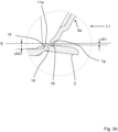
- Figure 4 shows a conductor connection terminal 1 with an insulating housing 19 in a side sectional view with a busbar component 2 arranged in the insulating housing 19.
- Two clamping springs 3a, 3b are arranged on the busbar component 2 at diametrically opposite ends.
- the clamping springs 3a, 3b have a contact leg 4a, 4b, which merges into a spring arch 5a, 5b and extends into a clamping leg 6a, 6b.
- the clamping legs 6a, 6b each have a spring clamping edge 7a, 7b, wherein the spring clamping edges 7a, 7b are connected to the Busbar component 2 forms a first clamping point for a first electrical conductor to be clamped and a second clamping point for a second electrical conductor to be clamped.
- the conductor connection terminal 1 has two actuating levers 20a, 20b, whereby each actuating lever 20a, 20b interacts with a clamping spring 3a, 3b, so that the actuating levers 20a, 20b are designed to deflect the clamping legs 6a, 6b.
- the clamping points for the electrical conductors can be opened and/or closed by the actuating levers.
- the conductor connection terminal 1 has a conductor stop 21, wherein the conductor stop 21 is arranged on the insulating housing 2.
- the conductor stop serves to position the first electrical conductor to be connected and the second electrical conductor to be connected, wherein the conductor stop 21 is arranged in the region of the recess 14 of the busbar component 2.
- the conductor stop 21 is guided through the recess 14 in the base section 12 of the busbar component 14.
- the insulating housing 19 is transparent at least in the region of the recess 14. By forming a transparent insulating housing, the insertion depth of the electrical conductors to be connected can be controlled, wherein the user can actively check through the insulating housing 19 whether the respective electrical conductor is positioned on the conductor stop 21.
- test opening 22 is arranged on the conductor connection terminal 1, wherein the test opening 22 extends from a surface of the insulating housing 19 through the insulating housing 19 to the busbar component 2.
- the test opening 22 extends transversely, in particular orthogonally to the first conductor insertion direction L1.
- the busbar component 2 can be contacted with external measuring devices, for example, through the test opening 22.
Landscapes
- Installation Of Bus-Bars (AREA)
- Connections Arranged To Contact A Plurality Of Conductors (AREA)
- Multi-Conductor Connections (AREA)
Applications Claiming Priority (1)
| Application Number | Priority Date | Filing Date | Title |
|---|---|---|---|
| DE202020100839.0U DE202020100839U1 (de) | 2020-02-17 | 2020-02-17 | Leiteranschlussklemme |
Publications (2)
| Publication Number | Publication Date |
|---|---|
| EP3866267A1 EP3866267A1 (de) | 2021-08-18 |
| EP3866267B1 true EP3866267B1 (de) | 2024-08-07 |
Family
ID=74666522
Family Applications (1)
| Application Number | Title | Priority Date | Filing Date |
|---|---|---|---|
| EP21157524.6A Active EP3866267B1 (de) | 2020-02-17 | 2021-02-17 | Leiteranschlussklemme |
Country Status (5)
| Country | Link |
|---|---|
| US (1) | US11329403B2 (https=) |
| EP (1) | EP3866267B1 (https=) |
| JP (1) | JP7749327B2 (https=) |
| CN (1) | CN113270741A (https=) |
| DE (2) | DE202020100839U1 (https=) |
Families Citing this family (6)
| Publication number | Priority date | Publication date | Assignee | Title |
|---|---|---|---|---|
| JP2021174693A (ja) * | 2020-04-27 | 2021-11-01 | 株式会社オートネットワーク技術研究所 | 中継コネクタ |
| DE102020120151A1 (de) * | 2020-07-30 | 2022-02-03 | WAGO Verwaltungsgesellschaft mit beschränkter Haftung | Verbindungsklemme zum Verbinden elektrischer Leiter |
| DE202022102833U1 (de) * | 2022-05-23 | 2023-08-25 | Electro Terminal Gmbh & Co Kg | Klemme mit Lösehebel und Drücker |
| CN220692414U (zh) * | 2022-06-06 | 2024-03-29 | 江门市创艺电器有限公司 | 一种连接端子 |
| CN115799853A (zh) * | 2022-12-16 | 2023-03-14 | 尤提乐电气有限公司 | 一种免焊接的互锁装配的夹线结构 |
| DE202025102468U1 (de) | 2025-05-06 | 2026-04-16 | Obo Bettermann Hungary Kft | Anschlusskontakt sowie Steckdose mit mehreren Anschlusskontakten |
Citations (3)
| Publication number | Priority date | Publication date | Assignee | Title |
|---|---|---|---|---|
| DE102014119421B4 (de) * | 2014-12-22 | 2017-02-02 | Wago Verwaltungsgesellschaft Mbh | Verbindungsklemme und Verfahren zur Montage einer Verbindungsklemme |
| DE102013101830B4 (de) * | 2013-01-08 | 2017-12-28 | Wago Verwaltungsgesellschaft Mbh | Elektrische Anschlussklemme und Verfahren zu dessen Montage |
| EP3460917A1 (en) * | 2017-09-20 | 2019-03-27 | Delphi Technologies, Inc. | Electrical connector |
Family Cites Families (13)
| Publication number | Priority date | Publication date | Assignee | Title |
|---|---|---|---|---|
| JPS52141184U (https=) * | 1976-04-21 | 1977-10-26 | ||
| JP2005235476A (ja) * | 2004-02-18 | 2005-09-02 | Smk Corp | 防水中継コネクタ |
| JP2006179337A (ja) * | 2004-12-22 | 2006-07-06 | Kawaguchi:Kk | 電線コネクタ |
| US7448901B2 (en) * | 2006-12-22 | 2008-11-11 | Tyco Electronics Corporation | Surface mount poke-in connector |
| DE102007050683B4 (de) * | 2007-10-22 | 2009-09-03 | Wago Verwaltungsgesellschaft Mbh | Leiteranschlussklemme |
| DE102013111574B4 (de) * | 2013-10-21 | 2017-01-12 | Wago Verwaltungsgesellschaft Mbh | Federkraftklemmanschluss und Steckverbinder |
| LU93039B1 (de) * | 2016-04-22 | 2017-10-27 | Phoenix Contact Gmbh & Co Kg Intellectual Property Licenses & Standards | Steckkontakt |
| CN107819226B (zh) | 2016-09-13 | 2020-01-14 | 进联电子科技(上海)有限公司 | 轨道端子的组合结构 |
| DE202016105702U1 (de) * | 2016-10-12 | 2018-01-15 | Wago Verwaltungsgesellschaft Mbh | Kontakteinsatz einer Leiteranschlussklemme und Leiteranschlussklemme |
| CN106505353B (zh) * | 2016-10-21 | 2019-07-26 | 中航光电科技股份有限公司 | 一种现场做线连接器 |
| CN207753189U (zh) | 2018-01-29 | 2018-08-21 | 余姚市信亿电子科技有限公司 | 导线快速连接器 |
| DE202018106242U1 (de) * | 2018-11-01 | 2020-02-14 | Wago Verwaltungsgesellschaft Mbh | Leiteranschlussklemme |
| DE102020104080C5 (de) * | 2020-02-17 | 2022-05-05 | WAGO Verwaltungsgesellschaft mit beschränkter Haftung | Leiteranschlussklemme und Verfahren zur Montage einer Leiteranschlussklemme |
-
2020
- 2020-02-17 DE DE202020100839.0U patent/DE202020100839U1/de active Active
-
2021
- 2021-02-07 CN CN202110175329.1A patent/CN113270741A/zh active Pending
- 2021-02-12 JP JP2021020437A patent/JP7749327B2/ja active Active
- 2021-02-16 US US17/176,877 patent/US11329403B2/en active Active
- 2021-02-17 EP EP21157524.6A patent/EP3866267B1/de active Active
- 2021-02-17 DE DE202021004452.3U patent/DE202021004452U1/de active Active
Patent Citations (3)
| Publication number | Priority date | Publication date | Assignee | Title |
|---|---|---|---|---|
| DE102013101830B4 (de) * | 2013-01-08 | 2017-12-28 | Wago Verwaltungsgesellschaft Mbh | Elektrische Anschlussklemme und Verfahren zu dessen Montage |
| DE102014119421B4 (de) * | 2014-12-22 | 2017-02-02 | Wago Verwaltungsgesellschaft Mbh | Verbindungsklemme und Verfahren zur Montage einer Verbindungsklemme |
| EP3460917A1 (en) * | 2017-09-20 | 2019-03-27 | Delphi Technologies, Inc. | Electrical connector |
Also Published As
| Publication number | Publication date |
|---|---|
| JP2021144931A (ja) | 2021-09-24 |
| US20210257753A1 (en) | 2021-08-19 |
| JP7749327B2 (ja) | 2025-10-06 |
| US11329403B2 (en) | 2022-05-10 |
| DE202020100839U1 (de) | 2021-05-25 |
| EP3866267A1 (de) | 2021-08-18 |
| DE202021004452U1 (de) | 2024-09-18 |
| CN113270741A (zh) | 2021-08-17 |
Similar Documents
| Publication | Publication Date | Title |
|---|---|---|
| EP3866267B1 (de) | Leiteranschlussklemme | |
| EP1657789B1 (de) | Anschlussvorrichtung zum Direktanschluss von Leiterenden und elektrisches Gerät mit einer derartigen Anschlussvorrichtung | |
| EP4224635B1 (de) | Leiteranschlussklemme | |
| EP2846408B1 (de) | Elektrische Anschlussklemme | |
| EP3118938B1 (de) | Steckverbinder | |
| WO2011047740A1 (de) | Federkraftanschlussklemme | |
| DE102018210233B4 (de) | Direktstecker und Direktsteckverbindung | |
| EP3490075A1 (de) | Set aus steckverbinder und halteelement sowie steckverbinder und halteelement hierzu | |
| DE202016100798U1 (de) | Federanschlussklemme | |
| EP3477792A1 (de) | Abgriffsteckverbinder und schutzerdungskontakt hierzu | |
| EP3866265B1 (de) | Federkraftklemmanschluss | |
| DE102012016281B4 (de) | Elektrische Verbindungsanordnung und deren Bauteile | |
| DE69607895T2 (de) | Elektrischer Verbinder mit zweistufiger Kontakhaltevorrichtung | |
| EP0865105B1 (de) | Steckbuchse bzw. elektrischer Steckverbinder mit Kontaktfeder und Steckbuchse als Anschlusskontakt | |
| DE102006001102B4 (de) | Verbindungseinrichtung zum Verbinden einer elektrischen Leitung mit einer Anschlusseinrichtung | |
| DE202017006317U1 (de) | Federkraftklemmanschluss für einen elektrischen Leiter | |
| EP4268327B1 (de) | Kontakteinsatz für eine leiteranschlussklemme | |
| EP4371189B1 (de) | Klemmkörper und verbindungsklemme für einen elektrischen leiter | |
| DE202017101632U1 (de) | Steckeranordnung und Verriegelungseinrichtung zur Verriegelung eines Gegensteckverbinders an einem Steckverbinder | |
| EP1923960B1 (de) | Flachsteckhülse | |
| LU503992B1 (de) | Reihenklemme mit Ausbruchfenster | |
| DE202014101570U1 (de) | Klemmfeder und Kontakteinheit | |
| EP3876362B1 (de) | Befestigungsklemme | |
| DE20106523U1 (de) | Reihenklemme mit Schneidkontakten und Anschlußvorrichtung | |
| DE102006020225B4 (de) | Reihenklemme mit einem Isoliergehäuse |
Legal Events
| Date | Code | Title | Description |
|---|---|---|---|
| REG | Reference to a national code |
Ref country code: DE Ref legal event code: R138 Ref document number: 202021004452 Country of ref document: DE Free format text: GERMAN DOCUMENT NUMBER IS 502021004636 |
|
| PUAI | Public reference made under article 153(3) epc to a published international application that has entered the european phase |
Free format text: ORIGINAL CODE: 0009012 |
|
| STAA | Information on the status of an ep patent application or granted ep patent |
Free format text: STATUS: THE APPLICATION HAS BEEN PUBLISHED |
|
| AK | Designated contracting states |
Kind code of ref document: A1 Designated state(s): AL AT BE BG CH CY CZ DE DK EE ES FI FR GB GR HR HU IE IS IT LI LT LU LV MC MK MT NL NO PL PT RO RS SE SI SK SM TR |
|
| STAA | Information on the status of an ep patent application or granted ep patent |
Free format text: STATUS: REQUEST FOR EXAMINATION WAS MADE |
|
| 17P | Request for examination filed |
Effective date: 20220126 |
|
| RBV | Designated contracting states (corrected) |
Designated state(s): AL AT BE BG CH CY CZ DE DK EE ES FI FR GB GR HR HU IE IS IT LI LT LU LV MC MK MT NL NO PL PT RO RS SE SI SK SM TR |
|
| STAA | Information on the status of an ep patent application or granted ep patent |
Free format text: STATUS: EXAMINATION IS IN PROGRESS |
|
| 17Q | First examination report despatched |
Effective date: 20230413 |
|
| GRAP | Despatch of communication of intention to grant a patent |
Free format text: ORIGINAL CODE: EPIDOSNIGR1 |
|
| STAA | Information on the status of an ep patent application or granted ep patent |
Free format text: STATUS: GRANT OF PATENT IS INTENDED |
|
| RIC1 | Information provided on ipc code assigned before grant |
Ipc: H01R 4/26 20060101ALN20231124BHEP Ipc: H01R 4/48 20060101AFI20231124BHEP |
|
| RIC1 | Information provided on ipc code assigned before grant |
Ipc: H01R 4/26 20060101ALN20231206BHEP Ipc: H01R 4/48 20060101AFI20231206BHEP |
|
| RIC1 | Information provided on ipc code assigned before grant |
Ipc: H01R 4/26 20060101ALN20231211BHEP Ipc: H01R 4/48 20060101AFI20231211BHEP |
|
| INTG | Intention to grant announced |
Effective date: 20240103 |
|
| GRAS | Grant fee paid |
Free format text: ORIGINAL CODE: EPIDOSNIGR3 |
|
| GRAJ | Information related to disapproval of communication of intention to grant by the applicant or resumption of examination proceedings by the epo deleted |
Free format text: ORIGINAL CODE: EPIDOSDIGR1 |
|
| GRAL | Information related to payment of fee for publishing/printing deleted |
Free format text: ORIGINAL CODE: EPIDOSDIGR3 |
|
| STAA | Information on the status of an ep patent application or granted ep patent |
Free format text: STATUS: EXAMINATION IS IN PROGRESS |
|
| GRAP | Despatch of communication of intention to grant a patent |
Free format text: ORIGINAL CODE: EPIDOSNIGR1 |
|
| STAA | Information on the status of an ep patent application or granted ep patent |
Free format text: STATUS: GRANT OF PATENT IS INTENDED |
|
| GRAJ | Information related to disapproval of communication of intention to grant by the applicant or resumption of examination proceedings by the epo deleted |
Free format text: ORIGINAL CODE: EPIDOSDIGR1 |
|
| GRAL | Information related to payment of fee for publishing/printing deleted |
Free format text: ORIGINAL CODE: EPIDOSDIGR3 |
|
| INTC | Intention to grant announced (deleted) | ||
| STAA | Information on the status of an ep patent application or granted ep patent |
Free format text: STATUS: EXAMINATION IS IN PROGRESS |
|
| RIC1 | Information provided on ipc code assigned before grant |
Ipc: H01R 4/26 20060101ALN20240507BHEP Ipc: H01R 4/48 20060101AFI20240507BHEP |
|
| INTG | Intention to grant announced |
Effective date: 20240524 |
|
| GRAP | Despatch of communication of intention to grant a patent |
Free format text: ORIGINAL CODE: EPIDOSNIGR1 |
|
| STAA | Information on the status of an ep patent application or granted ep patent |
Free format text: STATUS: GRANT OF PATENT IS INTENDED |
|
| GRAA | (expected) grant |
Free format text: ORIGINAL CODE: 0009210 |
|
| STAA | Information on the status of an ep patent application or granted ep patent |
Free format text: STATUS: THE PATENT HAS BEEN GRANTED |
|
| INTC | Intention to grant announced (deleted) | ||
| RIC1 | Information provided on ipc code assigned before grant |
Ipc: H01R 4/26 20060101ALN20240606BHEP Ipc: H01R 4/48 20060101AFI20240606BHEP |
|
| INTG | Intention to grant announced |
Effective date: 20240626 |
|
| AK | Designated contracting states |
Kind code of ref document: B1 Designated state(s): AL AT BE BG CH CY CZ DE DK EE ES FI FR GB GR HR HU IE IS IT LI LT LU LV MC MK MT NL NO PL PT RO RS SE SI SK SM TR |
|
| REG | Reference to a national code |
Ref country code: GB Ref legal event code: FG4D Free format text: NOT ENGLISH |
|
| REG | Reference to a national code |
Ref country code: CH Ref legal event code: EP |
|
| REG | Reference to a national code |
Ref country code: IE Ref legal event code: FG4D Free format text: LANGUAGE OF EP DOCUMENT: GERMAN |
|
| REG | Reference to a national code |
Ref country code: DE Ref legal event code: R096 Ref document number: 502021004636 Country of ref document: DE |
|
| REG | Reference to a national code |
Ref country code: LT Ref legal event code: MG9D |
|
| REG | Reference to a national code |
Ref country code: NL Ref legal event code: MP Effective date: 20240807 |
|
| PG25 | Lapsed in a contracting state [announced via postgrant information from national office to epo] |
Ref country code: NO Free format text: LAPSE BECAUSE OF FAILURE TO SUBMIT A TRANSLATION OF THE DESCRIPTION OR TO PAY THE FEE WITHIN THE PRESCRIBED TIME-LIMIT Effective date: 20241107 |
|
| PG25 | Lapsed in a contracting state [announced via postgrant information from national office to epo] |
Ref country code: GR Free format text: LAPSE BECAUSE OF FAILURE TO SUBMIT A TRANSLATION OF THE DESCRIPTION OR TO PAY THE FEE WITHIN THE PRESCRIBED TIME-LIMIT Effective date: 20241108 Ref country code: NL Free format text: LAPSE BECAUSE OF FAILURE TO SUBMIT A TRANSLATION OF THE DESCRIPTION OR TO PAY THE FEE WITHIN THE PRESCRIBED TIME-LIMIT Effective date: 20240807 Ref country code: FI Free format text: LAPSE BECAUSE OF FAILURE TO SUBMIT A TRANSLATION OF THE DESCRIPTION OR TO PAY THE FEE WITHIN THE PRESCRIBED TIME-LIMIT Effective date: 20240807 Ref country code: PL Free format text: LAPSE BECAUSE OF FAILURE TO SUBMIT A TRANSLATION OF THE DESCRIPTION OR TO PAY THE FEE WITHIN THE PRESCRIBED TIME-LIMIT Effective date: 20240807 Ref country code: PT Free format text: LAPSE BECAUSE OF FAILURE TO SUBMIT A TRANSLATION OF THE DESCRIPTION OR TO PAY THE FEE WITHIN THE PRESCRIBED TIME-LIMIT Effective date: 20241209 |
|
| PG25 | Lapsed in a contracting state [announced via postgrant information from national office to epo] |
Ref country code: BG Free format text: LAPSE BECAUSE OF FAILURE TO SUBMIT A TRANSLATION OF THE DESCRIPTION OR TO PAY THE FEE WITHIN THE PRESCRIBED TIME-LIMIT Effective date: 20240807 |
|
| PG25 | Lapsed in a contracting state [announced via postgrant information from national office to epo] |
Ref country code: LV Free format text: LAPSE BECAUSE OF FAILURE TO SUBMIT A TRANSLATION OF THE DESCRIPTION OR TO PAY THE FEE WITHIN THE PRESCRIBED TIME-LIMIT Effective date: 20240807 |
|
| PG25 | Lapsed in a contracting state [announced via postgrant information from national office to epo] |
Ref country code: IS Free format text: LAPSE BECAUSE OF FAILURE TO SUBMIT A TRANSLATION OF THE DESCRIPTION OR TO PAY THE FEE WITHIN THE PRESCRIBED TIME-LIMIT Effective date: 20241207 |
|
| PG25 | Lapsed in a contracting state [announced via postgrant information from national office to epo] |
Ref country code: HR Free format text: LAPSE BECAUSE OF FAILURE TO SUBMIT A TRANSLATION OF THE DESCRIPTION OR TO PAY THE FEE WITHIN THE PRESCRIBED TIME-LIMIT Effective date: 20240807 |
|
| PG25 | Lapsed in a contracting state [announced via postgrant information from national office to epo] |
Ref country code: RS Free format text: LAPSE BECAUSE OF FAILURE TO SUBMIT A TRANSLATION OF THE DESCRIPTION OR TO PAY THE FEE WITHIN THE PRESCRIBED TIME-LIMIT Effective date: 20241107 Ref country code: ES Free format text: LAPSE BECAUSE OF FAILURE TO SUBMIT A TRANSLATION OF THE DESCRIPTION OR TO PAY THE FEE WITHIN THE PRESCRIBED TIME-LIMIT Effective date: 20240807 |
|
| PG25 | Lapsed in a contracting state [announced via postgrant information from national office to epo] |
Ref country code: RS Free format text: LAPSE BECAUSE OF FAILURE TO SUBMIT A TRANSLATION OF THE DESCRIPTION OR TO PAY THE FEE WITHIN THE PRESCRIBED TIME-LIMIT Effective date: 20241107 Ref country code: PT Free format text: LAPSE BECAUSE OF FAILURE TO SUBMIT A TRANSLATION OF THE DESCRIPTION OR TO PAY THE FEE WITHIN THE PRESCRIBED TIME-LIMIT Effective date: 20241209 Ref country code: PL Free format text: LAPSE BECAUSE OF FAILURE TO SUBMIT A TRANSLATION OF THE DESCRIPTION OR TO PAY THE FEE WITHIN THE PRESCRIBED TIME-LIMIT Effective date: 20240807 Ref country code: NO Free format text: LAPSE BECAUSE OF FAILURE TO SUBMIT A TRANSLATION OF THE DESCRIPTION OR TO PAY THE FEE WITHIN THE PRESCRIBED TIME-LIMIT Effective date: 20241107 Ref country code: NL Free format text: LAPSE BECAUSE OF FAILURE TO SUBMIT A TRANSLATION OF THE DESCRIPTION OR TO PAY THE FEE WITHIN THE PRESCRIBED TIME-LIMIT Effective date: 20240807 Ref country code: LV Free format text: LAPSE BECAUSE OF FAILURE TO SUBMIT A TRANSLATION OF THE DESCRIPTION OR TO PAY THE FEE WITHIN THE PRESCRIBED TIME-LIMIT Effective date: 20240807 Ref country code: IS Free format text: LAPSE BECAUSE OF FAILURE TO SUBMIT A TRANSLATION OF THE DESCRIPTION OR TO PAY THE FEE WITHIN THE PRESCRIBED TIME-LIMIT Effective date: 20241207 Ref country code: HR Free format text: LAPSE BECAUSE OF FAILURE TO SUBMIT A TRANSLATION OF THE DESCRIPTION OR TO PAY THE FEE WITHIN THE PRESCRIBED TIME-LIMIT Effective date: 20240807 Ref country code: GR Free format text: LAPSE BECAUSE OF FAILURE TO SUBMIT A TRANSLATION OF THE DESCRIPTION OR TO PAY THE FEE WITHIN THE PRESCRIBED TIME-LIMIT Effective date: 20241108 Ref country code: FI Free format text: LAPSE BECAUSE OF FAILURE TO SUBMIT A TRANSLATION OF THE DESCRIPTION OR TO PAY THE FEE WITHIN THE PRESCRIBED TIME-LIMIT Effective date: 20240807 Ref country code: ES Free format text: LAPSE BECAUSE OF FAILURE TO SUBMIT A TRANSLATION OF THE DESCRIPTION OR TO PAY THE FEE WITHIN THE PRESCRIBED TIME-LIMIT Effective date: 20240807 Ref country code: BG Free format text: LAPSE BECAUSE OF FAILURE TO SUBMIT A TRANSLATION OF THE DESCRIPTION OR TO PAY THE FEE WITHIN THE PRESCRIBED TIME-LIMIT Effective date: 20240807 |
|
| PG25 | Lapsed in a contracting state [announced via postgrant information from national office to epo] |
Ref country code: DK Free format text: LAPSE BECAUSE OF FAILURE TO SUBMIT A TRANSLATION OF THE DESCRIPTION OR TO PAY THE FEE WITHIN THE PRESCRIBED TIME-LIMIT Effective date: 20240807 Ref country code: SM Free format text: LAPSE BECAUSE OF FAILURE TO SUBMIT A TRANSLATION OF THE DESCRIPTION OR TO PAY THE FEE WITHIN THE PRESCRIBED TIME-LIMIT Effective date: 20240807 |
|
| PG25 | Lapsed in a contracting state [announced via postgrant information from national office to epo] |
Ref country code: EE Free format text: LAPSE BECAUSE OF FAILURE TO SUBMIT A TRANSLATION OF THE DESCRIPTION OR TO PAY THE FEE WITHIN THE PRESCRIBED TIME-LIMIT Effective date: 20240807 |
|
| PGFP | Annual fee paid to national office [announced via postgrant information from national office to epo] |
Ref country code: AT Payment date: 20250417 Year of fee payment: 5 |
|
| PG25 | Lapsed in a contracting state [announced via postgrant information from national office to epo] |
Ref country code: CZ Free format text: LAPSE BECAUSE OF FAILURE TO SUBMIT A TRANSLATION OF THE DESCRIPTION OR TO PAY THE FEE WITHIN THE PRESCRIBED TIME-LIMIT Effective date: 20240807 |
|
| PG25 | Lapsed in a contracting state [announced via postgrant information from national office to epo] |
Ref country code: SK Free format text: LAPSE BECAUSE OF FAILURE TO SUBMIT A TRANSLATION OF THE DESCRIPTION OR TO PAY THE FEE WITHIN THE PRESCRIBED TIME-LIMIT Effective date: 20240807 |
|
| REG | Reference to a national code |
Ref country code: DE Ref legal event code: R097 Ref document number: 502021004636 Country of ref document: DE |
|
| PLBE | No opposition filed within time limit |
Free format text: ORIGINAL CODE: 0009261 |
|
| STAA | Information on the status of an ep patent application or granted ep patent |
Free format text: STATUS: NO OPPOSITION FILED WITHIN TIME LIMIT |
|
| 26N | No opposition filed |
Effective date: 20250508 |
|
| PG25 | Lapsed in a contracting state [announced via postgrant information from national office to epo] |
Ref country code: SE Free format text: LAPSE BECAUSE OF FAILURE TO SUBMIT A TRANSLATION OF THE DESCRIPTION OR TO PAY THE FEE WITHIN THE PRESCRIBED TIME-LIMIT Effective date: 20240807 |
|
| PG25 | Lapsed in a contracting state [announced via postgrant information from national office to epo] |
Ref country code: MC Free format text: LAPSE BECAUSE OF FAILURE TO SUBMIT A TRANSLATION OF THE DESCRIPTION OR TO PAY THE FEE WITHIN THE PRESCRIBED TIME-LIMIT Effective date: 20240807 |
|
| P01 | Opt-out of the competence of the unified patent court (upc) registered |
Free format text: CASE NUMBER: UPC_APP_2964_3866267/2025 Effective date: 20250811 |
|
| REG | Reference to a national code |
Ref country code: CH Ref legal event code: PL |
|
| PG25 | Lapsed in a contracting state [announced via postgrant information from national office to epo] |
Ref country code: LU Free format text: LAPSE BECAUSE OF NON-PAYMENT OF DUE FEES Effective date: 20250217 |
|
| PG25 | Lapsed in a contracting state [announced via postgrant information from national office to epo] |
Ref country code: CH Free format text: LAPSE BECAUSE OF NON-PAYMENT OF DUE FEES Effective date: 20250228 |
|
| GBPC | Gb: european patent ceased through non-payment of renewal fee |
Effective date: 20250217 |
|
| REG | Reference to a national code |
Ref country code: BE Ref legal event code: MM Effective date: 20250228 |
|
| PG25 | Lapsed in a contracting state [announced via postgrant information from national office to epo] |
Ref country code: GB Free format text: LAPSE BECAUSE OF NON-PAYMENT OF DUE FEES Effective date: 20250217 |
|
| PG25 | Lapsed in a contracting state [announced via postgrant information from national office to epo] |
Ref country code: FR Free format text: LAPSE BECAUSE OF NON-PAYMENT OF DUE FEES Effective date: 20250228 |
|
| PG25 | Lapsed in a contracting state [announced via postgrant information from national office to epo] |
Ref country code: BE Free format text: LAPSE BECAUSE OF NON-PAYMENT OF DUE FEES Effective date: 20250228 |
|
| PG25 | Lapsed in a contracting state [announced via postgrant information from national office to epo] |
Ref country code: IE Free format text: LAPSE BECAUSE OF NON-PAYMENT OF DUE FEES Effective date: 20250217 |
|
| PG25 | Lapsed in a contracting state [announced via postgrant information from national office to epo] |
Ref country code: IT Free format text: LAPSE BECAUSE OF FAILURE TO SUBMIT A TRANSLATION OF THE DESCRIPTION OR TO PAY THE FEE WITHIN THE PRESCRIBED TIME-LIMIT Effective date: 20240807 |
|
| PGFP | Annual fee paid to national office [announced via postgrant information from national office to epo] |
Ref country code: DE Payment date: 20260220 Year of fee payment: 6 |
|
| PG25 | Lapsed in a contracting state [announced via postgrant information from national office to epo] |
Ref country code: RO Free format text: LAPSE BECAUSE OF FAILURE TO SUBMIT A TRANSLATION OF THE DESCRIPTION OR TO PAY THE FEE WITHIN THE PRESCRIBED TIME-LIMIT Effective date: 20240807 |