EP3865811B1 - Magazin einer kanone - Google Patents
Magazin einer kanone Download PDFInfo
- Publication number
- EP3865811B1 EP3865811B1 EP21153287.4A EP21153287A EP3865811B1 EP 3865811 B1 EP3865811 B1 EP 3865811B1 EP 21153287 A EP21153287 A EP 21153287A EP 3865811 B1 EP3865811 B1 EP 3865811B1
- Authority
- EP
- European Patent Office
- Prior art keywords
- cartridge
- holding
- region
- magazine
- flap
- Prior art date
- Legal status (The legal status is an assumption and is not a legal conclusion. Google has not performed a legal analysis and makes no representation as to the accuracy of the status listed.)
- Active
Links
Images
Classifications
-
- F—MECHANICAL ENGINEERING; LIGHTING; HEATING; WEAPONS; BLASTING
- F42—AMMUNITION; BLASTING
- F42B—EXPLOSIVE CHARGES, e.g. FOR BLASTING, FIREWORKS, AMMUNITION
- F42B39/00—Packaging or storage of ammunition or explosive charges; Safety features thereof; Cartridge belts or bags
- F42B39/22—Locking of ammunition in transport containers
-
- F—MECHANICAL ENGINEERING; LIGHTING; HEATING; WEAPONS; BLASTING
- F41—WEAPONS
- F41A—FUNCTIONAL FEATURES OR DETAILS COMMON TO BOTH SMALLARMS AND ORDNANCE, e.g. CANNONS; MOUNTINGS FOR SMALLARMS OR ORDNANCE
- F41A9/00—Feeding or loading of ammunition; Magazines; Guiding means for the extracting of cartridges
- F41A9/01—Feeding of unbelted ammunition
- F41A9/06—Feeding of unbelted ammunition using cyclically moving conveyors, i.e. conveyors having ammunition pusher or carrier elements which are emptied or disengaged from the ammunition during the return stroke
- F41A9/09—Movable ammunition carriers or loading trays, e.g. for feeding from magazines
-
- F—MECHANICAL ENGINEERING; LIGHTING; HEATING; WEAPONS; BLASTING
- F41—WEAPONS
- F41A—FUNCTIONAL FEATURES OR DETAILS COMMON TO BOTH SMALLARMS AND ORDNANCE, e.g. CANNONS; MOUNTINGS FOR SMALLARMS OR ORDNANCE
- F41A9/00—Feeding or loading of ammunition; Magazines; Guiding means for the extracting of cartridges
- F41A9/61—Magazines
- F41A9/64—Magazines for unbelted ammunition
- F41A9/76—Magazines having an endless-chain conveyor
Definitions
- the invention relates to a magazine for a cannon, having the features of the preamble of patent claim 1.
- the magazines of armored vehicles have a bucket chain or a belt conveyor on which several containers, the so-called buckets, are arranged to hold cartridges.
- the containers are also known as ammunition loading containers.
- Magazines are also referred to below as ammunition feeders.
- cartridge and ammunition are used synonymously.
- Conventional cartridges have a case with a case diameter to hold a propellant charge.
- a projectile with a projectile diameter is connected to the case.
- the case diameter is larger than the projectile diameter.
- the cartridge is conical in the transition area.
- a magazine for a gun of an armored vehicle with a bucket chain is known.
- Several buckets for holding cartridges are arranged on the bucket chain.
- the containers have a cylindrical shape with two openings on the front, so that the cartridge can be fed to a removal point of the gun using a ram.
- Several openings are made in the containers, which are arranged axially and distributed over the circumference.
- Cartridges with a projectile and a casing can be fed and fixed, which have two different diameters, namely a larger casing diameter and a smaller projectile diameter.
- the cartridge is fixed to the outer circumference through the openings using several clamps.
- One clamp is on the projectile and pliers to the cartridge case. This protects the cartridge from shocks and vibrations.
- the DE 2 153 327 A shows a similar cylindrical ammunition carrier with a container for holding a cartridge, the container having a number of openings, with grippers arranged in the openings.
- the grippers are urged radially inwards against the projectile by actuating elements.
- the actuating elements are arranged on rods extending in the axial direction and are pre-tensioned by a spring, whereby the grippers deform inwards.
- a loading device with a container for holding a cartridge which has two supporting trays at the bottom on which the cartridge rests.
- the cartridge is fixed at the top with the help of two holding jaws, which are pivoted parallel to the axial direction of the cartridge.
- These holding jaws also only rest on a limited area of the cartridge in a holding position.
- the two holding jaws have a common pivoting mechanism for the simultaneous pivoting of the two holding jaws.
- the DE 34 09 018 A1 shows an ammunition loading container of an automatic loading device of a barrel weapon.
- the ammunition loading container has a semicircular cup on which the cartridge rests. The cup is offset several times so that a cartridge with different diameters is held securely over its entire length.
- the cartridge is supported in one area of a projectile head and one area of a case base.
- the cartridge is held in the cup with the help of two axially offset retaining clips.
- the retaining clips are opened to feed or remove the cartridge.
- the retaining clips only fix the cartridge in two small sections of the cartridge.
- One retaining clip is on the projectile head and one retaining clip is on the propellant case.
- the holding flap has a first region and an axially spaced second region, the first region being a first partially cylindrical region with a first radius, and the second region being a second partially cylindrical region with a second radius, the second radius being smaller than the first.
- a radial distance between the first area and an opposite bottom of the support shell is smaller than a radial distance between the second area and the opposite bottom of the support shell.
- the distance is measured in the radial direction as the minimum distance between the area of the holding flap and the inner surface of the support shell against which the cartridge rests, which is referred to here as the bottom.
- the ammunition can be held at the bullet head and the casing by closing a retaining flap.
- the ammunition can also be are supported radially by means of the retaining flaps, which means that pressure forces are distributed over a larger area. The risk of damage to the ammunition in the container before firing is therefore reduced.
- the partially cylindrical areas are designed as a type of constriction, i.e. they form a relatively short axial contact surface on the ammunition.
- the partially cylindrical surfaces extend over an axially longer area almost parallel to the outer peripheral surface of the ammunition, so that the contact surfaces are correspondingly large.
- the total contact surfaces of the at least one retaining flap are at least 35% of the surface of the cartridge. This further increases the protection of the cartridge against any impacts or shocks. It is also conceivable to achieve the size of the contact surface defined above if holes are made in the retaining flap for weight reasons.
- the retaining flap has a transition region which is formed between the first and the second region, wherein in the holding position between the transition region of the retaining flap and a transition region of the cartridge a third support surface is formed.
- the support surface between the retaining flap and the cartridge is further enlarged, so that the protection of the cartridge against impacts, vibrations or shocks is even more effective. Due to this transition area, cartridges with a complex shape can be transported safely.
- Cartridges are usually conical in the transition area between the casing and the projectile. In an advantageous embodiment of the invention, the transition area of the retaining flap is partially conical.
- the retaining flap conical in the transition area By also making the retaining flap conical in the transition area, it is ensured that a support surface is formed between the retaining flap and the cartridge in the holding position.
- the conicity fixes the cartridge in both a radial and an axial direction. In the partially cylindrical area, the axial fixation takes place only through friction and not additionally through positive locking.
- the carrier tray is advantageously designed at least partially, in particular over the entire length, in the shape of a hollow cylinder segment with an opening angle of less than 180°. It is possible to also support the cartridge in the area of the bullet head with an insert, or to form a holding rib on the carrier tray in the area of the bullet head. Due to this feature, the cartridge can be inserted into the carrier tray from above and also removed from the carrier tray upwards. Furthermore, the cartridge can be pushed in and out of the carrier tray in the axial direction of the cartridge. This provides great flexibility with regard to the use of handling devices that work together with the magazine.
- two retaining flaps are arranged mirror-symmetrically on the support shell, with the pivot axes of the two retaining flaps running parallel to a cartridge axis.
- Such an arrangement leads to a simple and therefore cost-effective construction of the retaining flaps and the associated pivot mechanisms.
- the torques to be transmitted by the pivot mechanisms are small because the projecting areas of the retaining flaps are short. Due to the symmetry, partially identical or at least similar components can also be used.
- a torsion spring is arranged on each of the retaining flaps to hold the retaining flap in the holding position.
- a torsion spring enables the retaining flap to be placed softly on the cartridge when the retaining flap is moved from the release position to the holding position. This process is carried out shortly after a new cartridge has been inserted into a container in the magazine. The soft placement prevents damage to the cartridge during this process.
- the torsion spring exerts light pressure on the cartridge from the retaining flap. This holds the cartridge securely in the container, i.e. it prevents the cartridge from being pushed out of the container in an undesirable manner when subjected to stress.
- the retaining flap has a total length that is greater than the length of the cartridge. Due to this feature, a support surface can be formed between the retaining flap and the cartridge, which extends over the entire length of the cartridge. This protects the cartridge from bending stresses. Since no area of the casing of the cartridge remains free opposite the retaining flap, no bending moments can arise.
- the first partially cylindrical area of the retaining flap has a length that is at least 20 to 30% of the total length of the retaining flap.
- the length of the first partially cylindrical area depends essentially on the cartridges to be transported. Typical lengths of the cases and the projectiles of the cartridges are in this range of 20 to 30% of the total length of the cartridge. This makes it possible to support the cartridge using the retaining flap over the entire length of the cartridge.
- the support shell is also adapted to the shape of the ammunition, i.e. that it is stepped in the area of the projectile head, or that a supporting insert is arranged, in particular fastened, in the support shell in the area of the projectile head.
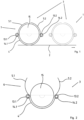
- FIG.1 is a schematic side view of an embodiment of a magazine 1 for a cannon.
- a plurality of containers 3 - the so-called cups - are arranged on a connecting means 2 - preferably in the form of a belt conveyor.
- the container 3 has a carrying tray 4 for receiving and conveying a cartridge 15.
- the connecting means 2 moves in the direction of the arrow so that the cartridge 15 is brought to a cannon, for example.
- the cartridge 15 lies in the carrying tray 4, which has the shape of a half-shell.
- the angular range of the cartridge 15, with which the cartridge 15 rests on the half-shell, is less than 180°.
- the container 3 also has two retaining flaps 5.1 and 5.2, which are pivotably arranged on the carrying tray 4.
- the retaining flap 5.1 is held on the carrying tray 4 by means of a hinge 13.1 and the retaining flap 5.2 is held on the carrying tray 4 by means of a hinge 13.2.
- the hinges 13.1 and 13.2 could, for example, be mounted using ball bearings.
- the two retaining flaps 5.1 and 5.2 are arranged mirror-symmetrically on two opposite sides of the cup 4. In Fig.1 the retaining flaps 5.1 and 5.2 are shown in a holding position 7. This is characterized by the fact that the retaining flaps 5.1 and 5.2 hold the cartridge 15 by resting on the cartridge 15 and are pressed against the cartridge 15 with a slight force.
- Fig.2 shows schematically a detail of the embodiment from Fig.1 with retaining flaps in a release position 6.
- the same reference numerals are used as for Fig.1 used. Since Fig.1 and Fig.2 in many respects similar, the description will be Fig.1 and only the changes are discussed below.
- Fig.2 shows only the container 3 here in a release position 6.
- the two retaining flaps 5.1 and 5.2 are pivoted outwards so that the cartridge 15 can be removed from the cup 3 from above. This happens, for example, in a transfer position of the container 3 to a cannon. In this release position 6, a cartridge 15 can still be fed into an empty container 3 from above. Due to the design of the carrying shell 4 as a half shell, it is also conceivable to push the cartridge 15 axially out of the cup 3 in the release position 6 of the container 3 or to push the cartridge 15 axially into an empty container 3.
- the two retaining flaps 5.1 and 5.2 are closed, i.e. they are moved from the release position 6 to the holding position 7. This is done using the torsion springs 14.1 and 14.2 and mechanisms not shown here. This closing preferably takes place automatically.
- the two mirror-symmetrically arranged retaining flaps 5.1 and 5.2 are moved simultaneously using such mechanisms and simultaneously hit the cartridge 15.
- the retaining flaps 5.1 and 5.2 rotate around an axis, which is formed by the two hinges 13.1 and 13.2. It is also conceivable to use two or more hinges per retaining flap 5.1 or 5.2.
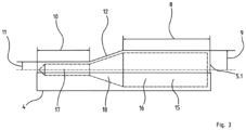
- Fig.3 is a schematic detail of the embodiment from Fig.1 in a side view perpendicular to the Fig.1
- the same reference numerals are used as for the previous figures. Since Fig.3 and the preceding figures are largely similar, the description is Fig.1 and only the changes are discussed below.
- the cartridge 15 has a cylindrical sleeve 16 for holding a propellant charge.
- a cylindrical projectile head 17 is connected to the sleeve 16 and is fired when the propellant charge is ignited.
- the sleeve 16 has a larger diameter than the projectile 17.
- the transition between the sleeve 16 and the projectile head 17 is formed by a cartridge cone 18.
- This cartridge cone 18 can be part of the sleeve 16 or part of the projectile head 17; the decisive factor is that there is a smooth transition between the sleeve 16 and the projectile head 17.
- Fig.3 further shows how the retaining flap 5.1 rests on the cartridge.
- Fig. 3 shows the container 3 in the holding position 7 with closed holding flaps 5.1 and 5.2.
- the holding flaps 5.1 and 5.2 have a sleeve area 8 with a sleeve area radius 9, whereby the sleeve area 8 rests on the sleeve 16 of the cartridge 15.
- the contact surface between the sleeve 16 and the holding flaps 5.1 and 5.2 is formed over the entire length of the sleeve 16.
- the retaining flaps 5.1 and 5.2 also have a projectile head area 10 with a projectile head area radius 11, whereby the projectile head area 10 rests on the projectile head 17 of the cartridge 15.
- the contact surface between the projectile head 17 and the retaining flaps 5.1 and 5.2 extends over almost the entire length of the projectile head 17. Only a short tip of the projectile head 17 does not touch the retaining flaps 5.1 and 5.2.
- the retaining flaps 5.1 and 5.2 also rest on the cartridge cone 18 of the cartridge 15.
- the retaining flaps 5.1 and 5.2 have a transition area 12 with which the cartridge is contacted.
- the retaining flaps 5.1 and 5.2 extend in the axial direction of the cartridge 15 over an area which is larger than the length of the cartridge 15.
- the cartridge 15 lies in the case area 8 on the support shell 4.
- the cartridge 15 is therefore only supported towards the support shell 4 by means of its case 16.
- the retaining flaps 5.1 and 5.2 also provide support via the other parts of the cartridge 15, it is nevertheless sufficiently protected from impacts and vibrations.
- the cartridge 15 can be supported in the front area.
- the described magazine 1 for a cannon is used in particular in automatic loaders or automatic ammunition feeders of armored vehicles.
Landscapes
- Engineering & Computer Science (AREA)
- General Engineering & Computer Science (AREA)
- Packaging Of Annular Or Rod-Shaped Articles, Wearing Apparel, Cassettes, Or The Like (AREA)
Description
- Die Erfindung betrifft ein Magazin für eine Kanone, mit den Merkmalen des Oberbegriffs des Patentanspruchs 1.
- Die Magazine z.B. gepanzerter Fahrzeuge weisen eine Becherkette oder einen Gurtförderer auf, an welchem mehrere Behälter, die sogenannten Becher, zur Aufnahme von Patronen angeordnet sind. Die Behälter werden ebenfalls als Munitionsladebehälter bezeichnet. Mit Hilfe der Becherkette oder des Gurtförderers werden die Patronen zur Ladeöffnung einer Kanone oder zu einem Zuführer einer Kanone befördert. Magazine werden im Folgenden auch als Munitionszuführung bezeichnet. Die Bezeichnungen Patrone und Munition werden synonym verwendet. Übliche Patronen weisen eine Hülse mit einem Hülsendurchmesser zur Aufnahme einer Treibladung auf. An die Hülse schließt ein Geschoss mit einem Geschossdurchmesser an. Dabei ist der Hülsendurchmesser größer als der Geschossdurchmesser. Im Übergangsbereich ist die Patrone konisch ausgeführt. Bei einem Schuss wird die Treibladung gezündet und das Geschoss durch ein Waffenrohr geschossen.
- Im Stand der Technik sind Halteklappen zum Fixieren der Munition in Form von Zangen, Haltebacken, Klammern und Greifern bekannt.
- Aus der
DE 30 31 203 C1 ist ein Magazin einer Kanone eines Panzerfahrzeuges mit einer Becherkette bekannt. Mehrere Becher zur Aufnahme von Patronen sind an der Becherkette angeordnet. Die Behälter weisen eine zylindrische Form mit zwei stirnseitigen Öffnungen auf, so dass die Patrone an einer Entnahmestelle der Kanone mittels eines Ansetzers zuführbar ist. In den Behältern sind mehrere Durchbrüche eingebracht, welche axial und über den Umfang verteilt angeordnet sind. Es sind Patronen mit einem Geschoss und einer Hülse förder- und fixierbar, welche zwei verschiedene Durchmesser, nämlich einen größeren Hülsen- und einen kleineren Geschossdurchmesser aufweisen. Durch die Durchbrüche hindurch wird die Patrone mithilfe von mehreren Zangen am Außenumfang fixiert. Dabei liegt eine Zange am Geschoss und einer Zange an der Hülse der Patrone an. So wird die Patrone vor Stößen und Vibrationen geschützt. - Die
DE 2 153 327 A zeigt einen ähnlichen zylindrischen Munitionsträger mit einem Behälter zur Aufnahme einer Patrone, wobei der Behälter mehrere Öffnungen aufweist, wobei in den Öffnungen Greifer angeordnet sind. Die Greifer werden durch Betätigungselemente nach radial innen gegen das Geschoss gedrängt. Die Betätigungselemente sind auf sich in axialer Richtung erstreckenden Stäben angeordnet und werden durch Feder vorgespannt, wodurch sich die Greifer nach innen verformen. - Aus der
DE 33 43 843 A1 ist eine Ladeeinrichtung mit einem Behälter zur Aufnahme einer Patrone bekannt, welcher zwei unten liegenden Tragschalen aufweist, auf welchen die Patrone aufliegt. Nach oben hin wird die Patrone mit Hilfe zweier Haltebacken fixiert, welche parallel zur Achsrichtung der Patrone schwenkbar gelagert sind. Auch diese Haltebacken liegen in einer Halteposition nur auf einem begrenzten Bereich der Patrone auf. Die beiden Haltebacken weisen einen gemeinsamen Schwenkmechanismus zur gleichzeitigen Schwenkung der beiden Haltebacken auf. - Die
DE 34 09 018 A1 zeigt einen Munitionsladebehälter einer automatischen Ladeeinrichtung einer Rohrwaffe. Der Munitionsladebehälter weist einen halbkreisbogenförmig ausgebildeten Becher auf, auf welchem die Patrone aufliegt. Der Becher ist mehrfach abgesetzt, so dass eine Patrone mit unterschiedlichen Durchmessern über ihren Gesamtlängenbereich stabil aufgenommen wird. Die Patrone wird dabei in einem Bereich eines Geschoßkopfes und einem Bereich eines Hülsenbodens abgestützt. Die Patrone wird mit Hilfe zweier axial versetzt angeordneter Halteklammern in dem Becher gehalten. Zur Zu- oder Abfuhr der Patrone werden die Halteklammern geöffnet. Auch hier fixieren die Halteklammern die Patrone nur in zwei kleinen Abschnitten der Patrone. Eine Halteklammer liegt am Geschosskopf und eine Halteklammer liegt an der Treibladungshülse an. - Alle vorgenannten Ausführungen eines Behälters zur Aufnahme einer Patrone in einem Magazin stützen bzw. halten die Patrone nur in einem kleinen Bereich. Insbesondere werden die Patronen von den beweglichen Teilen wie den Haltebacken, Greifern und Halteklammern nur über eine geringe Fläche kontaktiert. Der Bereich in welchem die Stempel bzw. Halteklappen die Patrone kontaktieren wird als Auflagefläche bezeichnet. Bei Stößen oder Vibrationen entstehen Drücke zwischen der Patrone und den Stempeln oder Halteklappen. Diese Drücke verteilen sich nur über diese begrenzten Auflageflächen, so dass relativ große Kräfte entstehen. Besonders empfindliche Patronen könnten somit durch besagte Stöße oder Vibrationen noch vor dem Abschuss beschädigt oder zerstört werden.
- Es ist somit die Aufgabe der Erfindung ein Magazin für eine Kanone mit einem Behälter zur Aufnahme von Patronen zu schaffen, welches auch empfindliche Patronen ausreichend und sicher vor Stößen und Vibrationen schützt.
- Die Aufgabe wird durch ein Magazin mit den Merkmalen des Patentanspruchs 1 gelöst, indem die Halteklappe einen ersten Bereich und einen axial beabstandeten zweiten Bereich aufweist, wobei der erste Bereich ein erster teilzylindrischer Bereich mit einem ersten Radius, und der zweite Bereich ein zweiter teilzylindrischer Bereich mit einem zweiten Radius ist, wobei der zweite Radius kleiner als der erste ist. Dies ermöglicht es, dass in der Halteposition zwischen dem ersten Bereich der Halteklappe und einem ersten Bereich der Patrone eine großflächige erste Auflagefläche ausgebildet ist, wobei in der Halteposition zwischen dem zweiten Bereich der Halteklappe und einem zweiten Bereich der Patrone eine großflächige zweite Auflagefläche ausbildet ist.
- In der Halteposition ist ein radialer Abstand zwischen dem ersten Bereich und einem gegenüberliegenden Boden der Tragschale geringer als ein radialer Abstand zwischen dem zweiten Bereich und dem gegenüberliegenden Boden der Tragschale. Der Abstand wird dabei jeweils in radialer Richtung als der minimale Abstand gemessen zwischen dem Bereich der Halteklappe und der Innenfläche der Tragschale an dem die Patrone anliegt, welcher hier als Boden bezeichnet wird.
- Dies ermöglicht es, dass durch Schließen einer Halteklappe die Munition bereits am Geschosskopf und an der Hülse gehalten werden kann. Die Munition kann ferner großflächiger radial mittels der Halteklappen abgestützt werden, wodurch Druckkräfte sich auf eine größere Fläche verteilen. Die Gefahr der Beschädigung der Munition im Behälter vor dem Abschuss ist daher verringert.
- Mittels dieser Merkmale ist eine besonders schonende Lagerung von Patronen in dem Behälter möglich. Die Halteklappe liegt in ihrer Halteposition mit der kompletten Auflagefläche des ersten Bereiches und des zweiten Bereiches auf der Patrone auf. Die Auflagefläche ist dadurch charakterisiert, dass an einer jeden Stelle der Auflagefläche ein Kontakt zwischen der Halteklappe und der Patrone besteht. Der Druck, welcher zwischen Patrone und Halteklappe wirkt, ist aufgrund der kompletten Auflagefläche her gering. Trotz des geringen Drucks, wird die Patrone sicher in dem Becher gehalten. So wird die Patrone besonders gut gegen Biegung, Stöße, Vibrationen oder Erschütterungen geschützt. Eine Beschädigung auch empfindlicher Patronen wird vermieden.
- Es ist denkbar, dass die teilzylindrischen Bereiche als eine Art Einschnürung ausgeführt sind, d.h. eine axial relativ kurze Auflagefläche an der Munition ausbilden. In bevorzugter Ausgestaltung erstrecken sich die teilzylindrischen Flächen jedoch über einen axial längeren Bereich nah parallel zur Außenumfangsfläche der Munition, so dass die Auflageflächen entsprechend groß sind.
- In einer Ausführungsform der Erfindung beträgt eine Summe der Auflageflächen der zumindest einen Halteklappe mindestens 35% der Oberfläche der Patrone. Dies erhöht weiter den Schutz der Patrone vor etwaigen Stößen oder Erschütterungen. Es ist auch denkbar die oben definierte Größe der Auflagefläche zu erreichen, wenn aus Gewichtsgründen Löcher in die Halteklappe eingebracht sind.
- In bevorzugter Ausgestaltung weist die Halteklappe einen Übergangsbereich auf, welcher zwischen dem ersten und dem zweiten Bereich ausgebildet ist, wobei in der Halteposition zwischen dem Übergangsbereich der Halteklappe und einem Übergangsbereich der Patrone eine dritte Auflagefläche ausbildet ist. Auf diese Weise wird die Auflagefläche zwischen Halteklappe und Patrone weiter vergrößert, so dass der Schutz der Patrone vor Stößen, Vibrationen oder Erschütterungen noch effektiver ist. Aufgrund dieses Übergangsbereiches sind Patronen sicher transportierbar, welche eine komplexe Form aufweisen. Üblicherweise sind Patronen in dem Übergangsbereich zwischen Hülse und Geschoss konisch ausgeführt. In einer vorteilhaften Ausführungsform der Erfindung ist der Übergangsbereich der Halteklappe teilkonisch ausgebildet. Durch eine ebenfalls konische Ausführung der Halteklappe im Übergangsbereich ist sichergestellt, dass sich in der Halteposition eine Auflagefläche zwischen Halteklappe und Patrone ausbildet. Durch die Konizität wird die Patrone sowohl in einer radialen wie auch in einer axialen Richtung fixiert. In den teilzylindrischen Bereich erfolgt die axiale Fixierung lediglich über Reibung und nicht zusätzlich über Formschluss.
- Vorteilhafterweise ist die Tragschale zumindest teilweise, insbesondere über die gesamte Länge hohlzylindersegmentförmig mit einem Öffnungswinkel kleiner als 180° ausgeführt. Es ist möglich, die Patrone im Geschosskopfbereich durch eine Einlage ebenfalls zu unterstützen, oder im Bereich des Geschosskopfes eine Halterippe an der Tragschale auszubilden. Es ist aufgrund dieses Merkmals die Patrone von oben in die Tragschale einlegbar und auch nach oben aus der Tragschale entnehmbar. Weiterhin ist ein hinaus- und hineinschieben der Patrone in die Tragschale in Achsrichtung der Patrone möglich. Es ist somit eine große Flexibilität bezüglich der Verwendung von Handhabungseinrichtungen gegeben, welche mit dem Magazin zusammenwirken.
- In einer vorteilhaften Ausführungsform der Erfindung sind zwei Halteklappen spiegelsymmetrisch an der Tragschale angeordnet, wobei die Schwenkachsen der beiden Halteklappen parallel zu einer Patronenachse verlaufen. Eine solche Anordnung führt zu einer einfachen und somit kostengünstigen Konstruktion der Halteklappen und der zugehörigen Schwenkmechanismen. Die von den Schwenkmechanismen zu übertragenen Drehmomente sind klein, da die auskragenden Bereiche der Halteklappen kurz sind. Aufgrund der Symmetrie können des Weiteren teilweise gleiche oder zumindest ähnliche Bauteile verwendet werden.
- In bevorzugter Ausgestaltung ist eine Drehfeder an jeder der Halteklappen angeordnet, um die Halteklappe in der Halteposition zu halten. Eine solche Drehfeder ermöglicht ein weiches Aufsetzen der Halteklappe auf der Patrone, wenn die Halteklappe von der Freigabe- in die Halteposition geführt wird. Dieser Vorgang wird durchgeführt, kurz nachdem eine neue Patrone in einen Behälter des Magazins eingelegt wurde. Durch das weiche Aufsetzten wird eine Beschädigung der Patrone bei diesem Vorgang vermieden. In der Halteposition selbst wird mittels der Drehfeder ein leichter Druck von der Halteklappe auf die Patrone ausgeübt. So wird die Patrone sicher in dem Behälter gehalten, d.h. es wird vermieden, dass die Patrone bei Belastungen unerwünscht aus dem Behälter hinausbefördert wird.
- In einer besonders bevorzugten Ausführungsform der Erfindung weist die Halteklappe eine Gesamtlänge auf, welche größer als die Länge der Patrone ist. Aufgrund dieses Merkmals ist eine Auflagefläche zwischen Halteklappe und Patrone ausbildbar, welche sich über die komplette Länge der Patrone erstreckt. So ist die Patrone vor Biegebelastungen geschützt. Da kein Mantelbereich der Patrone gegenüber der Halteklappe frei bleibt, können keine Biegemomente entstehen.
- Vorteilhafterweise weist der erste teilzylindrische Bereich der Halteklappe eine Länge auf, welche mindestens 20 bis 30% der Gesamtlänge der Halteklappe beträgt. Die Länge des ersten teilzylindrischen Bereichs hängt im Wesentlichen von den zu transportierenden Patronen ab. Übliche Längen der Hülsen und der Geschosse der Patronen liegen eben in diesem Bereich von 20 bis 30% der Gesamtlänge der Patrone. So ist eine Abstützung der Patrone mittels der Halteklappe über die gesamte Länge der Patrone möglich.
- Es ist möglich, dass die Tragschale ebenfalls an die Form der Munition angepasst ist, d.h. im Bereich des Geschosskopfes gestuft ausgebildet ist, oder dass innerhalb der Tragschale im Bereiches des Geschosskopfes ein unterstützender Einleger in der Tragschale angeordnet, insbesondere befestigt ist.
- Es gibt eine Vielzahl von Möglichkeiten, die Erfindung auszugestalten und weiterzubilden. Es darf zunächst auf die dem Patentanspruch 1 nachgeordneten Patentansprüche verwiesen werden. Im Folgenden wird nun eine bevorzugte Ausgestaltung der Erfindung anhand der Zeichnung und der dazugehörigen Beschreibung näher erläutert. In der Zeichnung zeigt:
-
Fig.1 schematisch ein Ausführungsbeispiel eines Magazins für eine Kanone in einer Seitenansicht im Schnitt, -
Fig.2 schematisch ein Detail des Ausführungsbeispiels ausFig.1 mit Halteklappen in einer Freigabeposition und -
Fig.3 schematisch ein Detail des Ausführungsbeispiels ausFig.1 in einer Seitenansicht senkrecht zu der ausFig.1 - In
Fig.1 ist schematisch ein Ausführungsbeispiel eines Magazins 1 für eine Kanone in einer Seitenansicht gezeigt. An einem Verbindungsmittel 2- vorzugsweise in Form eines Gurtförderer s - sind mehrere Behälter 3 - die sogenannten Becher - angeordnet. Der Behälter 3 weist eine Tragschale 4 zur Aufnahme und Förderung einer Patrone 15 auf. Bei Betrieb des Magazins 1 bewegt sich das Verbindungsmittel 2 in Richtung des Pfeiles, so dass die Patrone 15 zum Beispiel zu einer Kanone gebracht wird. Die Patrone 15 liegt in der Tragschale 4, welcher die Form einer Halbschale aufweist. Der Winkelbereich der Patrone 15, mit welchem die Patrone 15 auf der Halbschale aufliegt, beträgt weniger als 180°. Weiterhin weist der Behälter 3 zwei Halteklappen 5.1 und 5.2 auf, welche schwenkbar an der Tragschale 4 angeordnet sind. Die Halteklappe 5.1 ist mittels eines Scharniers 13.1 und die Halteklappe 5.2 ist mittels eines Scharniers 13.2 an der Tragschale 4 gehalten. Die Scharniere 13.1 und 13.2 könnten zum Beispiel mittels Kugellagern gelagert sein. Die beiden Halteklappen 5.1 und 5.2 sind an zwei gegenüberliegenden Seiten des Bechers 4 spiegelsymmetrisch angeordnet. InFig.1 sind die Halteklappen 5.1 und 5.2 in einer Halteposition 7 gezeigt. Diese ist dadurch charakterisiert, dass die Halteklappen 5.1 und 5.2 die Patrone 15 halten, indem Sie auf der Patrone 15 aufliegen und mit einer leichten Kraft gegen die Patrone 15 gedrückt werden. Diese Kräfte von den beiden Halteklappen 5.1 und 5.2 auf die Patrone 15 werden mit Hilfe von zwei Drehfedern 14.1 und 14.2 erzeugt, welche in die Scharniere 13.1 und 13.2 integriert sind. Die so erzeugten Kräfte verteilen sich auf einen großen Oberflächenbereich der Patrone 15, da zwei Auflageflächen zwischen den beiden Halteklappen 5.1 und 5.2 und der Patrone 15 entsprechend groß sind. Diese Auflageflächen entstehen durch einen Kontakt zwischen den beiden Halteklappen 5.1 und 5.2 und der Patrone 15 und erstrecken sich nahezu über die komplette obere Hälfte der Patrone 15. -
Fig.2 zeigt schematisch ein Detail des Ausführungsbeispiels ausFig.1 mit Halteklappen in einer Freigabeposition 6. Es werden die gleichen Bezugszeichen wie zuFig.1 verwendet. Da sichFig.1 und Fig.2 in weiten Teilen gleichen, wird auf die Beschreibung zuFig.1 verwiesen und im Folgenden nur auf die Änderungen eingegangen. -
Fig.2 zeigt ausschließlich den Behälter 3 hier in einer Freigabeposition 6. Die beiden Halteklappen 5.1 und 5.2 sind nach außen hin verschwenkt, so dass die Patrone 15 von oben aus dem Becher 3 herausnehmbar ist. Dies geschieht zum Beispiel in einer Übergabeposition des Behälters 3 zu einer Kanone. In dieser Freigabeposition 6 ist weiterhin eine Patrone 15 in einen leeren Behälter 3 von oben zuführbar. Aufgrund der Ausführung der Tragschale 4 als Halbschale ist es weiterhin denkbar, die Patrone 15 in der Freigabeposition 6 des Behälters 3 axial aus dem Becher 3 herauszuschieben bzw. die Patrone 15 in einen leeren Behälter 3 axial hineinzuschieben. - Nachdem eine Patrone 15 in die Tragschale 4 eingelegt wurde, werden die beiden Halteklappen 5.1 und 5.2 zugeklappt, d.h. sie werden von der Freigabeposition 6 in die Halteposition 7 überführt. Dies geschieht mithilfe der Drehfedern 14.1 und 14.2 sowie hier nicht gezeigter Mechaniken. Dieses Zuklappen erfolgt vorzugsweise automatisch. Die beiden spiegelsymmetrisch angeordneten Halteklappen 5.1 und 5.2 werden gleichzeitig mittels solcher Mechaniken bewegt und treffen gleichzeitig auf der Patrone 15 auf. Die Rotation der Halteklappen 5.1 und 5.2 erfolgt dabei um eine Achse, welche mittels der beiden Scharniere 13.1 und 13.2 gebildet werden. Es ist auch denkbar pro Halteklappe 5.1 bzw. 5.2 zwei oder mehrere Scharniere zu verwenden.
- In
Fig.3 ist schematisch ein Detail des Ausführungsbeispiels ausFig.1 in einer Seitenansicht senkrecht zu der ausFig.1 gezeigt. Es werden die gleichen Bezugszeichen wie zu den vorangehenden Figuren verwendet. Da sichFig.3 und die vorangehenden Figuren in weiten Teilen gleichen, wird auf die Beschreibung zuFig.1 verwiesen und im Folgenden nur auf die Änderungen eingegangen. - In der Ansicht aus
Fig.3 sind die verschiedenen Bereiche der Patrone 15 zu erkennen. Die Patrone 15 weist eine zylinderförmige Hülse 16 zur Aufnahme einer Treibladung auf. An die Hülse 16 schließt ein zylinderförmiges Geschosskopf 17 an, welches bei einer Zündung der Treibladung weggeschossen wird. Die Hülse 16 weist einen größeren Durchmesser auf als das Geschoss 17. Der Übergang zwischen der Hülse 16 und dem Geschosskopf 17 wird durch einen Patronenkonus 18 gebildet. Dieser Patronenkonus 18 kann Teil der Hülse 16 oder Teil des Geschosskopfes 17 sein, entscheidend ist, dass ein fließender Übergang zwischen der Hülse 16 und dem Geschosskopf 17 entsteht. -
Fig.3 stellt weiterhin dar, wie die Halteklappe 5.1 auf der Patrone aufliegt.Fig. 3 zeigt den Behälter 3 in der Halteposition 7 mit geschlossenen Halteklappen 5.1 und 5.2. Die Halteklappen 5.1 und 5.2 weisen einen Hülsenbereich 8 mit einem Hülsenbereichsradius 9 auf, wobei der Hülsenbereich 8 auf der Hülse 16 der Patrone 15 aufliegt. Die Auflagefläche zwischen der Hülse 16 und den Halteklappen 5.1 und 5.2 bildet sich über die komplette Länge der Hülse 16 aus. - Die Halteklappen 5.1 und 5.2 weisen weiterhin einen Geschosskopfbereich 10 mit einem Geschosskopfbereichsradius 11 auf, wobei der Geschosskopfbereich 10 auf dem Geschosskopf 17 der Patrone 15 aufliegt. Die Auflagefläche zwischen dem Geschosskopf 17und den Halteklappen 5.1 und 5.2 bildet sich über fast die komplette Länge des Geschosskopfes 17 aus. Lediglich eine kurze Spitze des Geschosskopfes 17 berührt die Halteklappen 5.1 und 5.2 nicht.
- Die Halteklappen 5.1 und 5.2 liegen ebenfalls auf dem Patronenkonus 18 der Patrone 15 auf. Dazu weisen die Halteklappen 5.1 und 5.2 einen Übergangsbereich 12 auf, mit welchem die Patrone kontaktiert wird. Die Halteklappen 5.1 und 5.2 erstrecken sich in Achsrichtung der Patrone 15 über einen Bereich, welcher größer als die Länge der Patrone 15 ist.
- Die Patrone 15 liegt in dem Hülsenbereich 8 auf der Tragschale 4. Zur Tragschale 4 hin wird die Patrone 15 somit lediglich mittels ihrer Hülse 16 abgestützt. Da zu den Halteklappen 5.1 und 5.2 aber eine Abstützung auch über die weiteren Teile der Patrone 15 erfolgt, ist sie dennoch ausreichend vor Stößen und Vibrationen geschützt. Es kann eine Abstützung der Patrone 15 im vorderen Bereich erfolgen.
- Das beschriebene Magazin 1 für eine Kanone kommt insbesondere in Automatikladern bzw. automatischen Munitionszuführungen von Panzerfahrzeugen zum Einsatz.
-
- 1
- Magazin
- 2
- Verbindungsmittel
- 3
- Behälter oder Becher
- 4
- Tragschale
- 5.1
- Halteklappe
- 5.2
- Halteklappe
- 6
- Freigabeposition
- 7
- Halteposition
- 8
- Hülsenbereich
- 9
- Hülsenbereichsradius
- 10
- Geschosskopfbereich
- 11
- Geschosskopfbereichsradius
- 12
- Übergangsbereich
- 13.1
- Scharnier
- 13.2
- Scharnier
- 14.1
- Drehfeder
- 14.2
- Drehfeder
- 15
- Patrone
- 16
- Hülse
- 17
- Geschosskopf
- 18
- Patronenkonus
Claims (10)
- Magazin (1) für eine Kanone, mit mehreren Behältern (3) zur Aufnahme jeweils einer Patrone (15), wobei die Behälter (3) mit einem Verbindungsmittel (2) miteinander verbunden sind, wobei zumindest ein Behälter (3) eine Tragschale (4) und zumindest eine Halteklappe (5.1, 5.2) aufweist, wobei die Halteklappe (5.1, 5.2) schwenkbar an der Tragschale (4) gehalten ist, wobei die Halteklappe (5.1, 5.2) zwischen einer Freigabe- (6) und einer Halteposition (7) hin- und her schwenkbar ist,
dadurch gekennzeichnet, dass
die Halteklappe (5.1, 5.2) einen ersten Bereich (8) und einen axial beabstandeten zweiten Bereich (10) aufweist, wobei der erste Bereich (8) ein erster teilzylindrischer Bereich (8) mit einem ersten Radius (9), und der zweite Bereich (10) ein zweiter teilzylindrischer Bereich (10) mit einem zweiten Radius (11) ist, wobei der zweite Radius (11) kleiner als der erste (9) ist. - Magazin nach Anspruch 1,
dadurch gekennzeichnet, dass
in der Halteposition (7) zwischen dem ersten Bereich der Halteklappe (8) und einem ersten Bereich der Patrone (16) eine erste Auflagefläche ausgebildet ist, wobei in der Halteposition (7) zwischen dem zweiten Bereich der Halteklappe (10) und einem zweiten Bereich der Patrone (17) eine zweite Auflagefläche ausbildet ist. - Magazin (1) nach Anspruch 2,
dadurch gekennzeichnet, dass
eine Summe der Auflageflächen der zumindest einen Halteklappe (5.1, 5.2) mindestens 35% der Oberfläche der Patrone (15) beträgt. - Magazin (1) nach Anspruch 3,
dadurch gekennzeichnet, dass
die Halteklappe (5.1, 5.2) einen Übergangsbereich (12) aufweist, welcher zwischen dem ersten (8) und dem zweiten Bereich (10) ausgebildet ist, wobei in der Halteposition (7) zwischen dem Übergangsbereich (12) der Halteklappe und einem Übergangsbereich der Patrone (18) eine dritte Auflagefläche ausgebildet ist. - Magazin (1) nach Anspruch 4,
dadurch gekennzeichnet, dass
der Übergangsbereich (12) der Halteklappe teilkonisch ausgeführt ist. - Magazin (1) nach einem der vorstehenden Ansprüche,
dadurch gekennzeichnet, dass
die Tragschale (4) zylindersegmentförmig mit einem Öffnungswinkel kleiner als 180° ausgebildet ist. - Magazin (1) nach einem der vorstehenden Ansprüche,
dadurch gekennzeichnet, dass
zwei Halteklappen (5.1, 5.2) spiegelsymmetrisch an der Tragschale (4) angeordnet sind, wobei die Schwenkachsen der beiden Halteklappen (5.1, 5.2) parallel zu einer Patronenachse verlaufen. - Magazin (1) nach einem der vorstehenden Ansprüche,
dadurch gekennzeichnet, dass
eine Drehfeder (14.1, 14.2) an der Halteklappe (5.1, 5.2) angeordnet ist, um die Halteklappe (5.1, 5.2) in der Halteposition (7) zu halten. - Magazin (1) nach einem der vorstehenden Ansprüche,
dadurch gekennzeichnet, dass
die Halteklappe (5.1, 5.2) eine Gesamtlänge aufweist, welche größer als die Länge der Patrone (15) ist. - Magazin (1) nach einem der vorstehenden Ansprüche,
dadurch gekennzeichnet, dass
der erste Bereich (8) der Halteklappe (5.1, 5.2) eine Länge aufweist, welche mindestens 20 bis 30% der Gesamtlänge der Halteklappe (5.1, 5.2) beträgt.
Applications Claiming Priority (1)
| Application Number | Priority Date | Filing Date | Title |
|---|---|---|---|
| DE102020103813.5A DE102020103813B4 (de) | 2020-02-13 | 2020-02-13 | Magazin einer Kanone |
Publications (2)
| Publication Number | Publication Date |
|---|---|
| EP3865811A1 EP3865811A1 (de) | 2021-08-18 |
| EP3865811B1 true EP3865811B1 (de) | 2024-12-04 |
Family
ID=74236077
Family Applications (1)
| Application Number | Title | Priority Date | Filing Date |
|---|---|---|---|
| EP21153287.4A Active EP3865811B1 (de) | 2020-02-13 | 2021-01-25 | Magazin einer kanone |
Country Status (5)
| Country | Link |
|---|---|
| EP (1) | EP3865811B1 (de) |
| DE (1) | DE102020103813B4 (de) |
| FI (1) | FI3865811T3 (de) |
| HU (1) | HUE071042T2 (de) |
| LT (1) | LT3865811T (de) |
Families Citing this family (2)
| Publication number | Priority date | Publication date | Assignee | Title |
|---|---|---|---|---|
| FR3079024B1 (fr) | 2018-03-15 | 2020-05-15 | Tiag Industries | Conteneur pour modules de poudre propulsive |
| DE102024101079A1 (de) * | 2024-01-15 | 2025-07-17 | Rheinmetall Landsysteme Gmbh | Munitionsladekiste und system |
Family Cites Families (14)
| Publication number | Priority date | Publication date | Assignee | Title |
|---|---|---|---|---|
| US3688639A (en) | 1971-01-28 | 1972-09-05 | Gen Motors Corp | Ammunition canister |
| FR2443041A1 (fr) | 1978-11-30 | 1980-06-27 | France Etat | Dispositif de chargement automatique d'un canon integre dans une tourelle de char |
| EP0022286B1 (de) | 1979-07-06 | 1982-11-03 | Werkzeugmaschinenfabrik Oerlikon-Bührle AG | Ladeautomat für ein Panzerfahrzeug |
| DE3031203C1 (de) | 1980-08-19 | 1985-07-25 | KUKA Wehrtechnik GmbH, 8900 Augsburg | Behaelter zur Aufnahme und Zufuehrung einer Patrone |
| DE3343843A1 (de) | 1983-12-03 | 1985-06-13 | Rheinmetall GmbH, 4000 Düsseldorf | Ladeeinrichtung einer rohrwaffe |
| DE3409018A1 (de) | 1984-03-13 | 1985-09-26 | Rheinmetall GmbH, 4000 Düsseldorf | Munitionsbehaelter einer automatischen ladeeinrichtung |
| DE3612208C2 (de) | 1986-04-11 | 1998-02-05 | Kuka Wehrtechnik Gmbh | Vorrichtung zum Laden einer Panzerwaffe |
| JPH0616313Y2 (ja) | 1986-04-24 | 1994-04-27 | 防衛庁技術研究本部長 | 給弾装置 |
| DE4126199C2 (de) | 1991-08-08 | 1994-06-23 | Rheinmetall Gmbh | Munitionsbehälter |
| US5675109A (en) | 1996-03-01 | 1997-10-07 | Lockheed Martin Corporation | Passive ammunition magazine for combat vehicles |
| US6679454B2 (en) | 2002-04-15 | 2004-01-20 | The Boeing Company | Radial sonobuoy launcher |
| SE534616C2 (sv) | 2009-10-21 | 2011-10-25 | Bae Systems Bofors Ab | Automatiserat laddningsmagasin |
| FR3059093B1 (fr) | 2016-11-21 | 2019-05-31 | Tiag Industries | Conteneur pour munition de gros calibre |
| FR3079024B1 (fr) | 2018-03-15 | 2020-05-15 | Tiag Industries | Conteneur pour modules de poudre propulsive |
-
2020
- 2020-02-13 DE DE102020103813.5A patent/DE102020103813B4/de active Active
-
2021
- 2021-01-25 HU HUE21153287A patent/HUE071042T2/hu unknown
- 2021-01-25 FI FIEP21153287.4T patent/FI3865811T3/fi active
- 2021-01-25 LT LTEP21153287.4T patent/LT3865811T/lt unknown
- 2021-01-25 EP EP21153287.4A patent/EP3865811B1/de active Active
Also Published As
| Publication number | Publication date |
|---|---|
| EP3865811A1 (de) | 2021-08-18 |
| FI3865811T3 (fi) | 2025-03-12 |
| LT3865811T (lt) | 2025-03-25 |
| HUE071042T2 (hu) | 2025-07-28 |
| DE102020103813B4 (de) | 2026-04-23 |
| DE102020103813A1 (de) | 2021-08-19 |
Similar Documents
| Publication | Publication Date | Title |
|---|---|---|
| EP0157111B1 (de) | Munitionsbehälter einer automatischen Ladeeinrichtung | |
| DE2501425C2 (de) | Geschoßzuführungsvorrichtung an einem waffentragenden Fahrzeug | |
| DE3635738C2 (de) | ||
| EP3865811A1 (de) | Magazin einer kanone | |
| DE102019106848A1 (de) | Treibladungsportioniereinrichtung mit einem expandierbaren Halteelement | |
| DE4126199C2 (de) | Munitionsbehälter | |
| DE69215653T2 (de) | Becher und Magazinförderer | |
| EP0557751B1 (de) | Panzerhaubitze mit schwenkbaren Ladearm und Kettenmagazin für die Munition | |
| CH666740A5 (de) | Blendenlafettierung fuer eine automatische rohrwaffe, insbesondere maschinenkanone. | |
| DE19748829C2 (de) | Verpackungsbehälter für großkalibrige Munition | |
| DE19514988C2 (de) | Verpackungsbehälter für großkalibrige Munition | |
| DE4135273C2 (de) | Ansetzerkopf mit integriertem Auszieher für Munition | |
| DE69223485T2 (de) | Munitionsmagazin, insbesondere für Kampfpanzer | |
| EP1020700A2 (de) | Vorrichtung zur berührungslosen Zündereinstellung für grosskalibrige Geschosse | |
| DE2153327A1 (de) | Munitionsträger | |
| DE3125406C2 (de) | ||
| WO2023285209A1 (de) | Zuführvorrichtung zum beladen und entladen eines radial öffnenden munitionsbechers für ein automatisches ladesystem eines geschützes | |
| DE69908707T2 (de) | Förderschale für modulare treibladung | |
| DE2623582C2 (de) | Raketengeschoß mit Ausklappleitwerk und Treibspiegel | |
| DE3343843C2 (de) | ||
| DE102017107442B4 (de) | Vorrichtung zum Laden einer Rohrwaffe mit Munitionskörpern | |
| EP4107465B1 (de) | Magazin | |
| DE68909211T2 (de) | Treibkäfig für Geschosse. | |
| EP1764576B1 (de) | Magazin für eine automatisch schiessende Waffe | |
| DE3902761C2 (de) |
Legal Events
| Date | Code | Title | Description |
|---|---|---|---|
| PUAI | Public reference made under article 153(3) epc to a published international application that has entered the european phase |
Free format text: ORIGINAL CODE: 0009012 |
|
| STAA | Information on the status of an ep patent application or granted ep patent |
Free format text: STATUS: THE APPLICATION HAS BEEN PUBLISHED |
|
| AK | Designated contracting states |
Kind code of ref document: A1 Designated state(s): AL AT BE BG CH CY CZ DE DK EE ES FI FR GB GR HR HU IE IS IT LI LT LU LV MC MK MT NL NO PL PT RO RS SE SI SK SM TR |
|
| STAA | Information on the status of an ep patent application or granted ep patent |
Free format text: STATUS: REQUEST FOR EXAMINATION WAS MADE |
|
| 17P | Request for examination filed |
Effective date: 20220218 |
|
| RBV | Designated contracting states (corrected) |
Designated state(s): AL AT BE BG CH CY CZ DE DK EE ES FI FR GB GR HR HU IE IS IT LI LT LU LV MC MK MT NL NO PL PT RO RS SE SI SK SM TR |
|
| STAA | Information on the status of an ep patent application or granted ep patent |
Free format text: STATUS: EXAMINATION IS IN PROGRESS |
|
| 17Q | First examination report despatched |
Effective date: 20230927 |
|
| GRAP | Despatch of communication of intention to grant a patent |
Free format text: ORIGINAL CODE: EPIDOSNIGR1 |
|
| STAA | Information on the status of an ep patent application or granted ep patent |
Free format text: STATUS: GRANT OF PATENT IS INTENDED |
|
| RIC1 | Information provided on ipc code assigned before grant |
Ipc: F41A 9/76 20060101ALI20240808BHEP Ipc: F41A 9/09 20060101ALI20240808BHEP Ipc: F42B 39/22 20060101AFI20240808BHEP |
|
| INTG | Intention to grant announced |
Effective date: 20240902 |
|
| GRAS | Grant fee paid |
Free format text: ORIGINAL CODE: EPIDOSNIGR3 |
|
| GRAA | (expected) grant |
Free format text: ORIGINAL CODE: 0009210 |
|
| STAA | Information on the status of an ep patent application or granted ep patent |
Free format text: STATUS: THE PATENT HAS BEEN GRANTED |
|
| AK | Designated contracting states |
Kind code of ref document: B1 Designated state(s): AL AT BE BG CH CY CZ DE DK EE ES FI FR GB GR HR HU IE IS IT LI LT LU LV MC MK MT NL NO PL PT RO RS SE SI SK SM TR |
|
| REG | Reference to a national code |
Ref country code: CH Ref legal event code: EP |
|
| REG | Reference to a national code |
Ref country code: DE Ref legal event code: R096 Ref document number: 502021005971 Country of ref document: DE |
|
| REG | Reference to a national code |
Ref country code: IE Ref legal event code: FG4D Free format text: LANGUAGE OF EP DOCUMENT: GERMAN |
|
| REG | Reference to a national code |
Ref country code: NL Ref legal event code: FP Ref country code: FI Ref legal event code: FGE |
|
| REG | Reference to a national code |
Ref country code: SE Ref legal event code: TRGR |
|
| PG25 | Lapsed in a contracting state [announced via postgrant information from national office to epo] |
Ref country code: HR Free format text: LAPSE BECAUSE OF FAILURE TO SUBMIT A TRANSLATION OF THE DESCRIPTION OR TO PAY THE FEE WITHIN THE PRESCRIBED TIME-LIMIT Effective date: 20241204 |
|
| PG25 | Lapsed in a contracting state [announced via postgrant information from national office to epo] |
Ref country code: BG Free format text: LAPSE BECAUSE OF FAILURE TO SUBMIT A TRANSLATION OF THE DESCRIPTION OR TO PAY THE FEE WITHIN THE PRESCRIBED TIME-LIMIT Effective date: 20241204 |
|
| PG25 | Lapsed in a contracting state [announced via postgrant information from national office to epo] |
Ref country code: ES Free format text: LAPSE BECAUSE OF FAILURE TO SUBMIT A TRANSLATION OF THE DESCRIPTION OR TO PAY THE FEE WITHIN THE PRESCRIBED TIME-LIMIT Effective date: 20241204 |
|
| PG25 | Lapsed in a contracting state [announced via postgrant information from national office to epo] |
Ref country code: NO Free format text: LAPSE BECAUSE OF FAILURE TO SUBMIT A TRANSLATION OF THE DESCRIPTION OR TO PAY THE FEE WITHIN THE PRESCRIBED TIME-LIMIT Effective date: 20250304 |
|
| PG25 | Lapsed in a contracting state [announced via postgrant information from national office to epo] |
Ref country code: LV Free format text: LAPSE BECAUSE OF FAILURE TO SUBMIT A TRANSLATION OF THE DESCRIPTION OR TO PAY THE FEE WITHIN THE PRESCRIBED TIME-LIMIT Effective date: 20241204 Ref country code: GR Free format text: LAPSE BECAUSE OF FAILURE TO SUBMIT A TRANSLATION OF THE DESCRIPTION OR TO PAY THE FEE WITHIN THE PRESCRIBED TIME-LIMIT Effective date: 20250305 |
|
| PGFP | Annual fee paid to national office [announced via postgrant information from national office to epo] |
Ref country code: AT Payment date: 20250417 Year of fee payment: 5 |
|
| PG25 | Lapsed in a contracting state [announced via postgrant information from national office to epo] |
Ref country code: RS Free format text: LAPSE BECAUSE OF FAILURE TO SUBMIT A TRANSLATION OF THE DESCRIPTION OR TO PAY THE FEE WITHIN THE PRESCRIBED TIME-LIMIT Effective date: 20250304 |
|
| PG25 | Lapsed in a contracting state [announced via postgrant information from national office to epo] |
Ref country code: SM Free format text: LAPSE BECAUSE OF FAILURE TO SUBMIT A TRANSLATION OF THE DESCRIPTION OR TO PAY THE FEE WITHIN THE PRESCRIBED TIME-LIMIT Effective date: 20241204 |
|
| PG25 | Lapsed in a contracting state [announced via postgrant information from national office to epo] |
Ref country code: PL Free format text: LAPSE BECAUSE OF FAILURE TO SUBMIT A TRANSLATION OF THE DESCRIPTION OR TO PAY THE FEE WITHIN THE PRESCRIBED TIME-LIMIT Effective date: 20241204 |
|
| PG25 | Lapsed in a contracting state [announced via postgrant information from national office to epo] |
Ref country code: IS Free format text: LAPSE BECAUSE OF FAILURE TO SUBMIT A TRANSLATION OF THE DESCRIPTION OR TO PAY THE FEE WITHIN THE PRESCRIBED TIME-LIMIT Effective date: 20250404 |
|
| PG25 | Lapsed in a contracting state [announced via postgrant information from national office to epo] |
Ref country code: PT Free format text: LAPSE BECAUSE OF FAILURE TO SUBMIT A TRANSLATION OF THE DESCRIPTION OR TO PAY THE FEE WITHIN THE PRESCRIBED TIME-LIMIT Effective date: 20250404 |
|
| PG25 | Lapsed in a contracting state [announced via postgrant information from national office to epo] |
Ref country code: EE Free format text: LAPSE BECAUSE OF FAILURE TO SUBMIT A TRANSLATION OF THE DESCRIPTION OR TO PAY THE FEE WITHIN THE PRESCRIBED TIME-LIMIT Effective date: 20241204 |
|
| PG25 | Lapsed in a contracting state [announced via postgrant information from national office to epo] |
Ref country code: RO Free format text: LAPSE BECAUSE OF FAILURE TO SUBMIT A TRANSLATION OF THE DESCRIPTION OR TO PAY THE FEE WITHIN THE PRESCRIBED TIME-LIMIT Effective date: 20241204 |
|
| PG25 | Lapsed in a contracting state [announced via postgrant information from national office to epo] |
Ref country code: SK Free format text: LAPSE BECAUSE OF FAILURE TO SUBMIT A TRANSLATION OF THE DESCRIPTION OR TO PAY THE FEE WITHIN THE PRESCRIBED TIME-LIMIT Effective date: 20241204 |
|
| PG25 | Lapsed in a contracting state [announced via postgrant information from national office to epo] |
Ref country code: CZ Free format text: LAPSE BECAUSE OF FAILURE TO SUBMIT A TRANSLATION OF THE DESCRIPTION OR TO PAY THE FEE WITHIN THE PRESCRIBED TIME-LIMIT Effective date: 20241204 |
|
| REG | Reference to a national code |
Ref country code: HU Ref legal event code: AG4A Ref document number: E071042 Country of ref document: HU |
|
| REG | Reference to a national code |
Ref country code: CH Ref legal event code: PL |
|
| REG | Reference to a national code |
Ref country code: DE Ref legal event code: R097 Ref document number: 502021005971 Country of ref document: DE |
|
| PG25 | Lapsed in a contracting state [announced via postgrant information from national office to epo] |
Ref country code: LU Free format text: LAPSE BECAUSE OF NON-PAYMENT OF DUE FEES Effective date: 20250125 Ref country code: MC Free format text: LAPSE BECAUSE OF FAILURE TO SUBMIT A TRANSLATION OF THE DESCRIPTION OR TO PAY THE FEE WITHIN THE PRESCRIBED TIME-LIMIT Effective date: 20241204 |
|
| PG25 | Lapsed in a contracting state [announced via postgrant information from national office to epo] |
Ref country code: DK Free format text: LAPSE BECAUSE OF FAILURE TO SUBMIT A TRANSLATION OF THE DESCRIPTION OR TO PAY THE FEE WITHIN THE PRESCRIBED TIME-LIMIT Effective date: 20241204 |
|
| PLBE | No opposition filed within time limit |
Free format text: ORIGINAL CODE: 0009261 |
|
| STAA | Information on the status of an ep patent application or granted ep patent |
Free format text: STATUS: NO OPPOSITION FILED WITHIN TIME LIMIT |
|
| PG25 | Lapsed in a contracting state [announced via postgrant information from national office to epo] |
Ref country code: CH Free format text: LAPSE BECAUSE OF NON-PAYMENT OF DUE FEES Effective date: 20250131 |
|
| 26N | No opposition filed |
Effective date: 20250905 |
|
| GBPC | Gb: european patent ceased through non-payment of renewal fee |
Effective date: 20250304 |
|
| PG25 | Lapsed in a contracting state [announced via postgrant information from national office to epo] |
Ref country code: GB Free format text: LAPSE BECAUSE OF NON-PAYMENT OF DUE FEES Effective date: 20250304 |
|
| PGFP | Annual fee paid to national office [announced via postgrant information from national office to epo] |
Ref country code: LT Payment date: 20251229 Year of fee payment: 6 |
|
| PG25 | Lapsed in a contracting state [announced via postgrant information from national office to epo] |
Ref country code: IE Free format text: LAPSE BECAUSE OF NON-PAYMENT OF DUE FEES Effective date: 20250125 |
|
| PGFP | Annual fee paid to national office [announced via postgrant information from national office to epo] |
Ref country code: NL Payment date: 20260121 Year of fee payment: 6 |
|
| PGFP | Annual fee paid to national office [announced via postgrant information from national office to epo] |
Ref country code: HU Payment date: 20260123 Year of fee payment: 6 |
|
| PGFP | Annual fee paid to national office [announced via postgrant information from national office to epo] |
Ref country code: SE Payment date: 20260121 Year of fee payment: 6 |
|
| PGFP | Annual fee paid to national office [announced via postgrant information from national office to epo] |
Ref country code: DE Payment date: 20260121 Year of fee payment: 6 |
|
| PGFP | Annual fee paid to national office [announced via postgrant information from national office to epo] |
Ref country code: FI Payment date: 20260129 Year of fee payment: 6 Ref country code: IT Payment date: 20260126 Year of fee payment: 6 Ref country code: BE Payment date: 20260121 Year of fee payment: 6 |
|
| PGFP | Annual fee paid to national office [announced via postgrant information from national office to epo] |
Ref country code: FR Payment date: 20260123 Year of fee payment: 6 |