EP3862673B1 - Kühlschrank - Google Patents
Kühlschrank Download PDFInfo
- Publication number
- EP3862673B1 EP3862673B1 EP19869400.2A EP19869400A EP3862673B1 EP 3862673 B1 EP3862673 B1 EP 3862673B1 EP 19869400 A EP19869400 A EP 19869400A EP 3862673 B1 EP3862673 B1 EP 3862673B1
- Authority
- EP
- European Patent Office
- Prior art keywords
- ice
- ice making
- tray
- heater
- water
- Prior art date
- Legal status (The legal status is an assumption and is not a legal conclusion. Google has not performed a legal analysis and makes no representation as to the accuracy of the status listed.)
- Active
Links
Images


Classifications
-
- F—MECHANICAL ENGINEERING; LIGHTING; HEATING; WEAPONS; BLASTING
- F25—REFRIGERATION OR COOLING; COMBINED HEATING AND REFRIGERATION SYSTEMS; HEAT PUMP SYSTEMS; MANUFACTURE OR STORAGE OF ICE; LIQUEFACTION SOLIDIFICATION OF GASES
- F25C—PRODUCING, WORKING OR HANDLING ICE
- F25C5/00—Working or handling ice
- F25C5/20—Distributing ice
- F25C5/22—Distributing ice particularly adapted for household refrigerators
-
- F—MECHANICAL ENGINEERING; LIGHTING; HEATING; WEAPONS; BLASTING
- F25—REFRIGERATION OR COOLING; COMBINED HEATING AND REFRIGERATION SYSTEMS; HEAT PUMP SYSTEMS; MANUFACTURE OR STORAGE OF ICE; LIQUEFACTION SOLIDIFICATION OF GASES
- F25C—PRODUCING, WORKING OR HANDLING ICE
- F25C1/00—Producing ice
- F25C1/18—Producing ice of a particular transparency or translucency, e.g. by injecting air
-
- F—MECHANICAL ENGINEERING; LIGHTING; HEATING; WEAPONS; BLASTING
- F25—REFRIGERATION OR COOLING; COMBINED HEATING AND REFRIGERATION SYSTEMS; HEAT PUMP SYSTEMS; MANUFACTURE OR STORAGE OF ICE; LIQUEFACTION SOLIDIFICATION OF GASES
- F25D—REFRIGERATORS; COLD ROOMS; ICE-BOXES; COOLING OR FREEZING APPARATUS NOT OTHERWISE PROVIDED FOR
- F25D11/00—Self-contained movable devices, e.g. domestic refrigerators
- F25D11/02—Self-contained movable devices, e.g. domestic refrigerators with cooling compartments at different temperatures
-
- F—MECHANICAL ENGINEERING; LIGHTING; HEATING; WEAPONS; BLASTING
- F25—REFRIGERATION OR COOLING; COMBINED HEATING AND REFRIGERATION SYSTEMS; HEAT PUMP SYSTEMS; MANUFACTURE OR STORAGE OF ICE; LIQUEFACTION SOLIDIFICATION OF GASES
- F25C—PRODUCING, WORKING OR HANDLING ICE
- F25C1/00—Producing ice
- F25C1/10—Producing ice by using rotating or otherwise moving moulds
-
- F—MECHANICAL ENGINEERING; LIGHTING; HEATING; WEAPONS; BLASTING
- F25—REFRIGERATION OR COOLING; COMBINED HEATING AND REFRIGERATION SYSTEMS; HEAT PUMP SYSTEMS; MANUFACTURE OR STORAGE OF ICE; LIQUEFACTION SOLIDIFICATION OF GASES
- F25C—PRODUCING, WORKING OR HANDLING ICE
- F25C1/00—Producing ice
- F25C1/22—Construction of moulds; Filling devices for moulds
- F25C1/24—Construction of moulds; Filling devices for moulds for refrigerators, e.g. freezing trays
-
- F—MECHANICAL ENGINEERING; LIGHTING; HEATING; WEAPONS; BLASTING
- F25—REFRIGERATION OR COOLING; COMBINED HEATING AND REFRIGERATION SYSTEMS; HEAT PUMP SYSTEMS; MANUFACTURE OR STORAGE OF ICE; LIQUEFACTION SOLIDIFICATION OF GASES
- F25C—PRODUCING, WORKING OR HANDLING ICE
- F25C5/00—Working or handling ice
- F25C5/02—Apparatus for disintegrating, removing or harvesting ice
- F25C5/04—Apparatus for disintegrating, removing or harvesting ice without the use of saws
- F25C5/08—Apparatus for disintegrating, removing or harvesting ice without the use of saws by heating bodies in contact with the ice
-
- F—MECHANICAL ENGINEERING; LIGHTING; HEATING; WEAPONS; BLASTING
- F25—REFRIGERATION OR COOLING; COMBINED HEATING AND REFRIGERATION SYSTEMS; HEAT PUMP SYSTEMS; MANUFACTURE OR STORAGE OF ICE; LIQUEFACTION SOLIDIFICATION OF GASES
- F25D—REFRIGERATORS; COLD ROOMS; ICE-BOXES; COOLING OR FREEZING APPARATUS NOT OTHERWISE PROVIDED FOR
- F25D11/00—Self-contained movable devices, e.g. domestic refrigerators
-
- F—MECHANICAL ENGINEERING; LIGHTING; HEATING; WEAPONS; BLASTING
- F25—REFRIGERATION OR COOLING; COMBINED HEATING AND REFRIGERATION SYSTEMS; HEAT PUMP SYSTEMS; MANUFACTURE OR STORAGE OF ICE; LIQUEFACTION SOLIDIFICATION OF GASES
- F25D—REFRIGERATORS; COLD ROOMS; ICE-BOXES; COOLING OR FREEZING APPARATUS NOT OTHERWISE PROVIDED FOR
- F25D23/00—General constructional features
- F25D23/006—General constructional features for mounting refrigerating machinery components
-
- F—MECHANICAL ENGINEERING; LIGHTING; HEATING; WEAPONS; BLASTING
- F25—REFRIGERATION OR COOLING; COMBINED HEATING AND REFRIGERATION SYSTEMS; HEAT PUMP SYSTEMS; MANUFACTURE OR STORAGE OF ICE; LIQUEFACTION SOLIDIFICATION OF GASES
- F25D—REFRIGERATORS; COLD ROOMS; ICE-BOXES; COOLING OR FREEZING APPARATUS NOT OTHERWISE PROVIDED FOR
- F25D23/00—General constructional features
- F25D23/06—Walls
- F25D23/062—Walls defining a cabinet
-
- F—MECHANICAL ENGINEERING; LIGHTING; HEATING; WEAPONS; BLASTING
- F25—REFRIGERATION OR COOLING; COMBINED HEATING AND REFRIGERATION SYSTEMS; HEAT PUMP SYSTEMS; MANUFACTURE OR STORAGE OF ICE; LIQUEFACTION SOLIDIFICATION OF GASES
- F25D—REFRIGERATORS; COLD ROOMS; ICE-BOXES; COOLING OR FREEZING APPARATUS NOT OTHERWISE PROVIDED FOR
- F25D23/00—General constructional features
- F25D23/12—Arrangements of compartments additional to cooling compartments; Combinations of refrigerators with other equipment, e.g. stove
- F25D23/126—Water cooler
-
- F—MECHANICAL ENGINEERING; LIGHTING; HEATING; WEAPONS; BLASTING
- F25—REFRIGERATION OR COOLING; COMBINED HEATING AND REFRIGERATION SYSTEMS; HEAT PUMP SYSTEMS; MANUFACTURE OR STORAGE OF ICE; LIQUEFACTION SOLIDIFICATION OF GASES
- F25D—REFRIGERATORS; COLD ROOMS; ICE-BOXES; COOLING OR FREEZING APPARATUS NOT OTHERWISE PROVIDED FOR
- F25D25/00—Charging, supporting, and discharging the articles to be cooled
- F25D25/02—Charging, supporting, and discharging the articles to be cooled by shelves
-
- F—MECHANICAL ENGINEERING; LIGHTING; HEATING; WEAPONS; BLASTING
- F25—REFRIGERATION OR COOLING; COMBINED HEATING AND REFRIGERATION SYSTEMS; HEAT PUMP SYSTEMS; MANUFACTURE OR STORAGE OF ICE; LIQUEFACTION SOLIDIFICATION OF GASES
- F25D—REFRIGERATORS; COLD ROOMS; ICE-BOXES; COOLING OR FREEZING APPARATUS NOT OTHERWISE PROVIDED FOR
- F25D29/00—Arrangement or mounting of control or safety devices
-
- F—MECHANICAL ENGINEERING; LIGHTING; HEATING; WEAPONS; BLASTING
- F25—REFRIGERATION OR COOLING; COMBINED HEATING AND REFRIGERATION SYSTEMS; HEAT PUMP SYSTEMS; MANUFACTURE OR STORAGE OF ICE; LIQUEFACTION SOLIDIFICATION OF GASES
- F25C—PRODUCING, WORKING OR HANDLING ICE
- F25C2400/00—Auxiliary features or devices for producing, working or handling ice
- F25C2400/10—Refrigerator units
-
- F—MECHANICAL ENGINEERING; LIGHTING; HEATING; WEAPONS; BLASTING
- F25—REFRIGERATION OR COOLING; COMBINED HEATING AND REFRIGERATION SYSTEMS; HEAT PUMP SYSTEMS; MANUFACTURE OR STORAGE OF ICE; LIQUEFACTION SOLIDIFICATION OF GASES
- F25C—PRODUCING, WORKING OR HANDLING ICE
- F25C2400/00—Auxiliary features or devices for producing, working or handling ice
- F25C2400/14—Water supply
-
- F—MECHANICAL ENGINEERING; LIGHTING; HEATING; WEAPONS; BLASTING
- F25—REFRIGERATION OR COOLING; COMBINED HEATING AND REFRIGERATION SYSTEMS; HEAT PUMP SYSTEMS; MANUFACTURE OR STORAGE OF ICE; LIQUEFACTION SOLIDIFICATION OF GASES
- F25C—PRODUCING, WORKING OR HANDLING ICE
- F25C2500/00—Problems to be solved
- F25C2500/02—Geometry problems
-
- F—MECHANICAL ENGINEERING; LIGHTING; HEATING; WEAPONS; BLASTING
- F25—REFRIGERATION OR COOLING; COMBINED HEATING AND REFRIGERATION SYSTEMS; HEAT PUMP SYSTEMS; MANUFACTURE OR STORAGE OF ICE; LIQUEFACTION SOLIDIFICATION OF GASES
- F25C—PRODUCING, WORKING OR HANDLING ICE
- F25C2600/00—Control issues
- F25C2600/02—Timing
-
- F—MECHANICAL ENGINEERING; LIGHTING; HEATING; WEAPONS; BLASTING
- F25—REFRIGERATION OR COOLING; COMBINED HEATING AND REFRIGERATION SYSTEMS; HEAT PUMP SYSTEMS; MANUFACTURE OR STORAGE OF ICE; LIQUEFACTION SOLIDIFICATION OF GASES
- F25C—PRODUCING, WORKING OR HANDLING ICE
- F25C2600/00—Control issues
- F25C2600/04—Control means
-
- F—MECHANICAL ENGINEERING; LIGHTING; HEATING; WEAPONS; BLASTING
- F25—REFRIGERATION OR COOLING; COMBINED HEATING AND REFRIGERATION SYSTEMS; HEAT PUMP SYSTEMS; MANUFACTURE OR STORAGE OF ICE; LIQUEFACTION SOLIDIFICATION OF GASES
- F25C—PRODUCING, WORKING OR HANDLING ICE
- F25C2700/00—Sensing or detecting of parameters; Sensors therefor
- F25C2700/12—Temperature of ice trays
-
- F—MECHANICAL ENGINEERING; LIGHTING; HEATING; WEAPONS; BLASTING
- F25—REFRIGERATION OR COOLING; COMBINED HEATING AND REFRIGERATION SYSTEMS; HEAT PUMP SYSTEMS; MANUFACTURE OR STORAGE OF ICE; LIQUEFACTION SOLIDIFICATION OF GASES
- F25D—REFRIGERATORS; COLD ROOMS; ICE-BOXES; COOLING OR FREEZING APPARATUS NOT OTHERWISE PROVIDED FOR
- F25D2400/00—General features of, or devices for refrigerators, cold rooms, ice-boxes, or for cooling or freezing apparatus not covered by any other subclass
- F25D2400/02—Refrigerators including a heater
Definitions
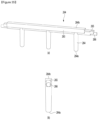
- the ice maker 200 may further include a shaft 440 (or a rotation shaft) that passes through the through-holes 282 and 404 together.
- a rotation arm 460 may be provided at each of both ends of the shaft 440.
- the shaft 440 may rotate by receiving rotational force from the driver 480.
- One end of the rotation arm 460 may be connected to one end of the spring 402, and thus, a position of the rotation arm 460 may move to an initial value by restoring force when the spring 402 is tensioned.
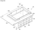
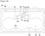
- the bracket 220 may be fixed to at least one surface of the storage chamber or to a cover member (to be described later) fixed to the storage chamber.
- the circumferential walls 303 spaced apart from each other in the Y-axis direction of FIG. 16 may include an extension wall 302e extending upward.
- the extension wall 302e may extend upward from a top surface of the circumferential wall 303.
- the first tray cover 300 may further include an upper wire guide part 310 guiding a wire connected to the ice separation heater 290, which will be described later.
- the upper wire guide part 310 may, for example, extend upward from the upper plate 301.
- the upper wire guide part 310 may include a first guide 312 and a second guide 314, which are spaced apart from each other.
- the first guide 312 and the second guide 314 may extend vertically upward from the upper plate 310.
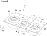
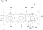
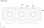
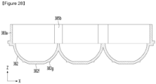
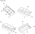
- the second tray 380 may define a second cell 381a which is another portion of the ice making cell 320a.
- the second tray 380 may include a second tray wall 381 defining a portion of the ice making cell 320a.
- the second tray 380 may define a plurality of second cells 381a.
- the plurality of second cells 381a may be arranged in a line.
- the plurality of second cells 381a may be arranged in an X-axis direction in FIG. 24 .
- the second tray wall 381 may define the plurality of second cells 381a.
- the second tray wall 381 may include a plurality of second cell walls 3811 which respectively define the plurality of second cells 381a.
- the two adjacent second cell walls 3811 may be connected to each other.
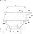
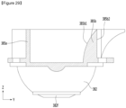
- the extension direction of at least a portion of the first part 384a may be the same as that of the second part 384b.
- the extension directions of the second part 384b and the third part 384c may be different from each other.
- the extension direction of the third part 384c may be different from that of the first part 384a.
- the third part 384a may have a constant curvature based on the Y-Z cutting surface. That is, the same curvature radius of the third part 384a may be constant in the longitudinal direction.
- the curvature of the second part 384b may be zero. When the second part 384b is not a straight line, the curvature of the second part 384b may be less than that of the third part 384a.
- the curvature radius of the second part 384b may be greater than that of the third part 384a.
- the third part 384c may also be described as including the first extension part 383a and the second extension part 383b extending in different directions with respect to the central line C1.
- a plurality of first coupling parts 361a may be provided on the wall facing the curved wall 363 of the vertical wall 361.
- the plurality of first coupling parts 361a may be spaced apart from each other in the X-axis direction of FIG. 30 .
- a first coupling groove 361b corresponding to each of the first coupling parts 361a may be provided.
- the first coupling groove 361b may be defined by recessing the vertical wall 361, and the first coupling part 361a may be provided in the recessed portion of the first coupling groove 361b.
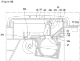
- a top surface 407a of the support body 407 may extend in the horizontal direction.
- the second tray supporter 400 may include a lower plate 401 that is stepped with the top surface 407a of the support body 40.
- the lower plate 401 may be disposed at a position higher than that of the top surface 407a of the support body 407.
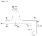
- the second tray supporter 400 may further include a link connection part 405a to which the pusher link 500 is coupled.
- the link connection part 405a may protrude from the vertical extension wall 405 in the X-axis direction.
- the link connection part 405a may be disposed on an area between the center line CL1 and the through-hole 404 with respect to FIG. 34 .
- a plurality of second heater coupling parts 409 coupled to the second heater case 420 may be further provided on the lower surface of the lower plate 401.
- the plurality of second heater coupling parts 409 may be arranged to be spaced apart from each other in the X-axis direction and/or the Y-axis direction.
- the first extension part 413a and the second extension part 413b may have different shapes with respect to the center line CL1.
- the first extension part 413a and the second extension part 413b may have shapes that are asymmetrical to each other with respect to the center line CL1.
- a length of the second extension part 413b may be greater than that of the first extension part 413a in the horizontal direction. That is, a length of the thermal conductivity of the second extension 413b is greater than that of the first extension part 413a.
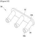
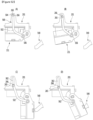
- FIG. 37 is a perspective view of a second pusher according to an embodiment.
- Part of the first region 214a may have the degree of heat transfer less than that of the other part of the first region 214a to reduce transfer of heat, which is transferred from the transparent ice heater 430 to the first region 314a, to the ice making cell 320a defined by the second region 214b.
- a portion of the first region 214a may have a degree of deformation resistance less than that of the other portion of the first region 214a and a degree of restoration greater than that of the other portion of the first region 214a.
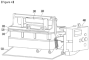
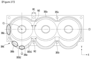
- the water supply part 240 may be disposed close to the first extension part 213a.
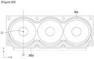
- the first tray assembly 301 may include a pair of guide slots 302, and the water supply part 240 may be disposed in a region between the pair of guide slots 302.
- a length of the guide slot 320 may be greater than the sum of a radius of the ice making cell 320a and a height of the auxiliary storage chamber 325.
- the water supply starts when the second tray 380 moves to the water supply position (S2).
- the controller 800 turns on the water supply valve 242, and when it is determined that a predetermined amount of water is supplied, the controller 800 may turn off the water supply valve 242.
- the controller 800 may turn off the water supply valve 242.
- the second portion 383 of the second tray 380 may surround the first tray 320.
- the second portion 383 of the second tray 380 may surround the second portion 323 of the first tray 320.
- the second portion 383 of the second tray 380 serves as a leakage prevention part. It is advantageous that a length of the leakage prevention part is provided as long as possible. This is because as the length of the leak prevention part increases, an amount of water leaking between the first and second tray assemblies is reduced.
- a length of the leakage prevention part defined by the second portion 383 may be greater than a distance from the center of the ice making cell 320a to the outer circumferential surface of the ice making cell 320a.
- the controller 800 may control the transparent ice heater 430 to be turned on in at least partial sections of the cold air supply part 900 supplying the cold air to the ice making cell 320a.
- the transparent ice heater 430 is turned on, since the heat of the transparent ice heater 430 is transferred to the ice making cell 320a, the ice making rate of the ice making cell 320a may be delayed.
- the ice making rate may be delayed so that the bubbles dissolved in the water inside the ice making cell 320a move from the portion at which ice is made toward the liquid water by the heat of the transparent ice heater 430 to make the transparent ice in the ice maker 200.
- the controller 800 may determine whether the turn-on condition of the transparent ice heater 430 is satisfied (S5). In this embodiment, the transparent ice heater 430 is not turned on immediately after the ice making is started, and the transparent ice heater 430 may be turned on only when the turn-on condition of the transparent ice heater 430 is satisfied (S6).
- the temperature of the ice in the ice making cell 320a is below zero.
- the temperature of the first tray 320 may be higher than the temperature of the ice in the ice making cell 320a.
- the temperature sensed by the second temperature sensor 700 may be below zero.
- the turn-on reference temperature may be set to the below-zero temperature.
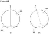
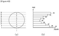
- FIG. 45 illustrates a unit height division of water and an output amount of transparent ice heater per unit height when the transparent ice heater is disposed as shown in FIG. 44(a) .
- the ice making rate in section E is the lowest, the ice making rate in the sections A and I is the fastest.
- the output of the transparent ice heater 430 may be gradually reduced in each section, or the output may be maintained in at least two sections.
- the output of the transparent ice heater 430 may increase from the minimum output to the end output.
- the end output may be equal to or different from the initial output.
- the output of the transparent ice heater 430 may incrementally increase in each section from the minimum output to the end output, or the output may be maintained in at least two sections.
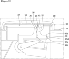
- FIG. 52 is a view illustrating an operation of a pusher link when the second tray assembly moves from the ice making position to the ice separation position.
- FIG. 52(a) illustrates the ice making position
- FIG. 52(b) illustrates the water supply position
- FIG. 52(c) illustrates the position at which the second tray contacts the second pusher
- FIG. 52(d) illustrates the ice separation position.
- the second edge 264b may be disposed outside the accommodation space 104.
- the second edge 264b may be disposed between the support surface 221d1 supporting the first tray assembly 201 in the bracket 220 and the first portion of the cover member 100.
- the second edge 264b may be lower than the top surface 221b 1 of the first fixing wall 221b of the bracket 220.
- the second edge 264b may be disposed outside the ice making cell 320a.
- the second edge 264b may be disposed outside the auxiliary storage chamber 325.
- the second edge 264b may be disposed higher than the support surface 221d1 of the support wall 221d. At the ice separation position, the second edge 264b may be higher than the through hole 241 of the water supply 240. At the iced position, the second edge 264b may be disposed higher than the lower end 241a of the first portion 241 of the water supply 240.
- Equation 1 and Table 1 are an equation and a table showing the relationship between the ice making amount and transparency.
- the refrigerator may include a mode for any one of transparencies determined by a combination of a1 and b1 or a combination of a2 and b2 described above.
- the refrigerator may include one or more modes for selecting transparency.
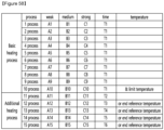
- the tenth process may be ended when the first set time T1 elapses and the temperature sensed by the second temperature sensor 700 reaches the limit temperature.
- the additional heating process may further include a process (a thirteenth process or a third additional process) of operating the transparent ice heater 430 with a set output A13 after the twelfth process.
- the thirteenth process may be performed when the twelfth process is performed for the third set time T3 but the temperature sensed by the second temperature sensor 700 does not reach the end reference temperature.
- the output C14 of the transparent ice heater 430 in the fourteenth process may be less than the output C13 of the transparent ice heater 430 in the thirteenth process.
- the output C14 of the transparent ice heater 430 in the fourteenth process when the target temperature of the freezing compartment 32 is strong may be equal to or different from the maximum output of the transparent ice heater 430 in the basic heating process when the target temperature of the freezing compartment 32 is medium.
- the output C15 of the transparent ice heater 430 in the fourteenth process may be less than the output C14 of the transparent ice heater 430 in the fourteenth process.
- the output C15 of the transparent ice heater 430 in the fifteenth process may be set to 1/2 of the output C14 of the transparent ice heater 430 in the fourteenth process.
- the additional heating process may include only the eleventh and twelfth processes, or may include only the thirteenth to fifteenth processes.
Landscapes
- Engineering & Computer Science (AREA)
- Physics & Mathematics (AREA)
- Mechanical Engineering (AREA)
- Thermal Sciences (AREA)
- General Engineering & Computer Science (AREA)
- Chemical & Material Sciences (AREA)
- Combustion & Propulsion (AREA)
- Production, Working, Storing, Or Distribution Of Ice (AREA)
- Devices That Are Associated With Refrigeration Equipment (AREA)
Claims (12)
- Kühlschrank (14), der Folgendes umfasst:eine Vorratskammer, die konfiguriert ist, Lebensmittel zu lagern;eine Kühlvorrichtung (900), die konfiguriert ist, der Vorratskammer Kälte zuzuführen;eine erste Einsatzanordnung (320), die konfiguriert ist, einen Abschnitt einer Eisbereitungszelle (200) zu definieren, die ein Raum ist, in dem Wasser durch die Kälte einer Phasenumwandlung in Eis unterworfen wird;eine zweite Einsatzanordnung (380), die konfiguriert ist, einen weiteren Abschnitt der Eisbereitungszelle (200) zu definieren, wobei die zweite Einsatzanordnung (380) mit einer Antriebsvorrichtung verbunden ist, so dass sie mit der ersten Einsatzanordnung (320) bei einem Eisbereitungsverfahren in Kontakt ist und von der ersten Einsatzanordnung (320) bei einem Eistrennverfahren beabstandet ist;eine Heizvorrichtung (430), die angrenzend an die erste Einsatzanordnung (320) und/oder die zweite Einsatzanordnung (380) angeordnet ist, undeine Steuerung (800), die konfiguriert ist, die Heizvorrichtung (430) zu steuern,wobei die Steuerung (800) die Heizvorrichtung (430) so steuert, dass sie in wenigstens einem Teilabschnitt eingeschaltet ist, während die Kühlvorrichtung (900) die Kälte zuführt, so dass Blasen, die im Wasser in der Eisbereitungszelle (200) gelöst sind, von einem Abschnitt, bei dem das Eis bereitet wird, zu dem Wasser bewegt werden, das sich in einem flüssigen Zustand befindet, um transparentes Eis zu bereiten,wobei die Steuerung (800) die Heizvorrichtung (430) so steuert, dass eine Eisbereitungsgeschwindigkeit des Wassers in der Eisbereitungszelle (200) in einem festgelegten Bereich gehalten wird, so dass sie niedriger als eine Eisbereitungsgeschwindigkeit ist, wenn die Eisbereitung in einem Zustand ausgeführt wird, in dem die Heizvorrichtung (430) ausgeschaltet ist,wobei das Verfahren zum Steuern der Heizvorrichtung (430) ein Basisheizverfahren und ein zusätzliches Heizverfahren, das nach dem Basisheizverfahren ausgeführt wird, umfasst,wobei in wenigstens einem Teilabschnitt des zusätzlichen Heizverfahrens die Steuerung (800) die Heizvorrichtung (430) so steuert, dass sie mit einer Wärmemenge betrieben wird, die kleiner oder gleich einer Wärmemenge der Heizvorrichtung (430) im Basisheizverfahren ist,wobei die Eisbereitungsmenge entsprechend der Eisbereitungsgeschwindigkeit innerhalb des festgelegten Bereichs größer oder gleich der Menge (Eisbereitungsmenge, wenn die Heizvorrichtung ausgeschaltet ist) × a1 (g/Tag) und kleiner oder gleich der Menge (Eisbereitungsmenge, wenn die Heizvorrichtung ausgeschaltet ist) × b 1 (g/Tag) ist, und wobeia1 0,25 oder mehr und 0,42 oder weniger beträgt, und b1 0,64 oder mehr und 0,91 oder weniger beträgt.
- Kühlschrank (14) nach Anspruch 1, wobei das Basisheizverfahren mehrere Verfahren umfasst, wobei die Steuerung (800) das Steuern so ausführt, dass sie von einem laufenden Verfahren zum nächsten Verfahren aus den mehreren Verfahren des Basisheizverfahrens fortschreitet, wenn eine festgelegte Zeit verstrichen ist oder wenn ein Wert, der durch einen Temperatursensor (700) gemessen wird, der konfiguriert ist, eine Temperatur von Wasser oder Eis in der Eisbereitungszelle (200) zu messen, einen Referenzwert erreicht, und
wobei ein letztes Verfahren des Basisheizverfahrens beendet ist, wenn der Wert, der durch diesen Temperatursensor (700) gemessen wird, den Referenzwert erreicht. - Kühlschrank (14) nach Anspruch 1, wobei das zusätzliche Heizverfahren mehrere Verfahren umfasst, wobei die Steuerung (800) das Steuern so ausführt, dass sie von einem laufenden Verfahren zu einem nächsten Verfahren aus den mehreren Verfahren des zusätzlichen Heizverfahrens fortschreitet, wenn eine festgelegte Zeit verstrichen ist oder wenn ein Wert, der durch den Temperatursensor (700) gemessen wird, der konfiguriert ist, eine Temperatur von Wasser oder Eis in der Eisbereitungszelle (200) zu messen, einen Referenzwert erreicht, und
wobei ein erstes Verfahren des zusätzlichen Heizverfahrens beendet ist, wenn eine festgelegte Zeit verstrichen ist. - Kühlschrank (14) nach Anspruch 1,wobei a1 0,29 oder mehr und 0,42 oder weniger beträgt, oder b1 0,64 oder mehr und 0,81 oder weniger beträgt, oderwobei a1 0,29 beträgt und b1 0,49 beträgt.
- Kühlschrank (14), der Folgendes umfasst:eine Vorratskammer, die konfiguriert ist, Lebensmittel zu lagern;eine Kühlvorrichtung (900), die konfiguriert ist, der Vorratskammer Kälte zuzuführen;einen ersten Temperatursensor (33), der konfiguriert ist, eine Temperatur in der Vorratskammer zu messen;eine erste Einsatzanordnung (320), die konfiguriert ist, einen Abschnitt einer Eisbereitungszelle (200) zu definieren, die ein Raum ist, in dem Wasser durch die Kälte einer Phasenumwandlung in Eis unterworfen wird;eine zweite Einsatzanordnung (380), die konfiguriert ist, einen weiteren Abschnitt der Eisbereitungszelle (200) zu definieren, wobei die zweite Einsatzanordnung (380) mit einer Antriebsvorrichtung verbunden ist, so dass sie mit der ersten Einsatzanordnung (320) bei einem Eisbereitungsverfahren in Kontakt ist und von der ersten Einsatzanordnung (320) bei einem Eistrennverfahren beabstandet ist;ein Wasserzufuhrteil, das konfiguriert ist, der Eisbereitungszelle (200) Wasser zuzuführen,einen zweiten Temperatursensor (700), der konfiguriert ist, eine Temperatur des Wassers oder des Eises in der Eisbereitungszelle zu messen;eine Heizvorrichtung (430), die angrenzend an die erste Einsatzanordnung (320) und/oder die zweite Einsatzanordnung (380) angeordnet ist, undeine Steuerung (800), die konfiguriert ist, die Heizvorrichtung (430) zu steuern,wobei die Steuerung (800) die Heizvorrichtung (430) so steuert, dass sie in wenigstens einem Teilabschnitt eingeschaltet ist, während die Kühlvorrichtung (900) die Kälte zuführt, so dass Blasen, die in dem Wasser in der Eisbereitungszelle (200) gelöst sind, von einem Abschnitt, bei dem das Eis bereitet wird, zu dem Wasser bewegt werden, das sich in einem flüssigen Zustand befindet, um transparentes Eis zu bereiten,wobei die Steuerung (800) die Kältemengenzufuhr der Kühlvorrichtung (900) und/oder die Wärmemenge der Heizvorrichtung (430) so steuert, dass sie sich entsprechend der höhenbezogenen Masse des Wassers in der Eisbereitungszelle (200) ändert, um eine Eisbereitungsgeschwindigkeit des Wassers in der Eisbereitungszelle in einem festgelegten Bereich zu halten, so dass sie niedriger als eine Eisbereitungsgeschwindigkeit ist, wenn die Eisbereitung in einem Zustand ausgeführt wird, in dem die Heizvorrichtung (430) ausgeschaltet ist,wobei die Eisbereitungsmenge entsprechend der Eisbereitungsgeschwindigkeit innerhalb des festgelegten Bereichs größer oder gleich der Menge (Eisbereitungsmenge, wenn die Heizvorrichtung ausgeschaltet ist) × a1 (g/Tag) und kleiner oder gleich der Menge (Eisbereitungsmenge, wenn die Heizvorrichtung ausgeschaltet ist) × b 1 (g/Tag) ist, und wobeia1 0,25 oder mehr und 0,42 oder weniger beträgt, und b1 0,64 oder mehr und 0,91 oder weniger beträgt.
- Kühlschrank (14) nach Anspruch 5, wobei die Steuerung (800) das Steuern so ausführt, dass die Kältemenge, die durch die Kühlvorrichtung (900) zugeführt wird, wenn die höhenbezogene Masse des Wassers in der Eisbereitungszelle (200) groß ist, größer als eine Kältemenge ist, die durch die Kühlvorrichtung (900) zugeführt wird, wenn die höhenbezogene Masse des Wassers in der Eisbereitungszelle (200) klein ist.
- Kühlschrank (14) nach Anspruch 5, wobei die Steuerung das Steuern so ausführt, dass die Wärmemenge, die durch die Heizvorrichtung zugeführt wird, wenn die höhenbezogene Masse des Wassers in der Eisbereitungszelle groß ist, kleiner als die Wärmemenge ist, die durch die Heizvorrichtung zugeführt wird, wenn die höhenbezogene Masse des Wassers in der Eisbereitungszelle klein ist.
- Kühlschrank (14) nach Anspruch 5,wobei a1 0,29 oder mehr und 0,42 oder weniger beträgt, oder b1 0,64 oder mehr und 0,81 oder weniger beträgt, oderwobei a1 0,29 beträgt und b1 0,49 beträgt.
- Kühlschrank (14), der Folgendes umfasst:eine Vorratskammer, die konfiguriert ist, Lebensmittel zu lagern;eine Kühlvorrichtung (900), die konfiguriert ist, der Vorratskammer Kälte zuzuführen;einen ersten Temperatursensor (33), der konfiguriert ist, eine Temperatur in der Vorratskammer zu messen;eine erste Einsatzanordnung (320), die konfiguriert ist, einen Abschnitt einer Eisbereitungszelle (200) zu definieren, die eine Raum ist, in dem Wasser durch die Kälte einer Phasenumwandlung in Eis unterworfen wird;eine zweite Einsatzanordnung (380), die konfiguriert ist, einen weiteren Abschnitt der Eisbereitungszelle (200) zu definieren, wobei die zweite Einsatzanordnung (380) mit einer Antriebsvorrichtung verbunden ist, so dass sie mit der ersten Einsatzanordnung (320) bei einem Eisbereitungsverfahren in Kontakt ist und von der ersten Einsatzanordnung (320) bei einem Eistrennverfahren beabstandet ist;ein Wasserzufuhrteil, das konfiguriert ist, der Eisbereitungszelle (200) Wasser zuzuführen,einen zweiten Temperatursensor (700), der konfiguriert ist, eine Temperatur des Wassers oder des Eises in der Eisbereitungszelle (200) zu messen;eine Heizvorrichtung (430), die angrenzend an die erste Einsatzanordnung (320) und/oder die zweite Einsatzanordnung (380) angeordnet ist, undeine Steuerung (800), die konfiguriert ist, die Heizvorrichtung (430) und die Antriebsvorrichtung zu steuern,wobei die Steuerung (800) die Kühlvorrichtung (900) so steuert, dass der Eisbereitungszelle (200) Kälte zugeführt wird, nachdem sich die zweite Einsatzanordnung (380) zu einer Eisbereitungsposition bewegt hat, wenn das Wasser der Eisbereitungszelle (200) vollständig zugeführt worden ist,wobei die Steuerung (800) die zweite Einsatzanordnung (380) so steuert, dass sich die zweite Einsatzanordnung (380) nach einer Bewegung zu einer Eistrennposition in einer Vorwärtsrichtung in einer Rückwärtsrichtung bewegt, um das Eis in der Eisbereitungszelle (200) herauszunehmen, wenn das Eis in der Eisbereitungszelle (200) vollständig bereitet ist,wobei die Steuerung (800) die zweite Einsatzanordnung (380) so steuert, dass die Zufuhr des Wassers beginnt, nachdem sich die zweite Einsatzanordnung (380) zu einer Wasserzufuhrposition in der Rückwärtsrichtung bewegt hat, wenn das Eis vollständig getrennt worden ist,wobei die Steuerung (800) die Heizvorrichtung (430) so steuert, dass sie in wenigstens einem Teilabschnitt eingeschaltet wird, während die Kühlvorrichtung (900) die Kälte zuführt, so dass Blasen, die im Wasser in der Eisbereitungszelle (200) gelöst sind, von einem Abschnitt, in dem das Eis bereitet wird, zu dem Wasser bewegt werden, das sich in einem flüssigen Zustand befindet, um transparentes Eis zu bereiten,wobei die Steuerung (800) die Heizvorrichtung (430) so steuert, dass dann, wenn eine Wärmeübertragungsmenge zwischen der Kälte in der Vorratskammer und dem Wasser der Eisbereitungszelle (200) zunimmt, die Wärmemenge der Heizvorrichtung (430) zunimmt, und wenn die Wärmeübertragungsmenge zwischen der Kälte in der Vorratskammer und dem Wasser der Eisbereitungszelle (200) abnimmt, die Wärmemenge der Heizvorrichtung (430) abnimmt, um eine Eisbereitungsgeschwindigkeit des Wassers in der Eisbereitungszelle (200) innerhalb eines festgelegten Bereichs zu halten, so dass sie kleiner als eine Eisbereitungsgeschwindigkeit ist, wenn die Eisbereitung in einem Zustand ausgeführt wird, in dem die Heizvorrichtung (430) ausgeschaltet ist,wobei die Eisbereitungsmenge entsprechend der Eisbereitungsgeschwindigkeit innerhalb des festgelegten Bereichs größer oder gleich der Menge (Eisbereitungsmenge, wenn die Heizvorrichtung ausgeschaltet ist) × a1 (g/Tag) und kleiner oder gleich der Menge (Eisbereitungsmenge, wenn die Heizvorrichtung ausgeschaltet ist) × b 1 (g/Tag) ist, und wobeia1 0,25 oder mehr und 0,42 oder weniger beträgt, und b1 0,64 oder mehr und 0,91 oder weniger beträgt.
- Kühlschrank (14) nach Anspruch 9,wobei a1 0,29 oder mehr und 0,42 oder weniger beträgt, oder b1 0,64 oder mehr und 0,81 oder weniger beträgt, oderwobei a1 0,35 oder mehr und 0,42 oder weniger beträgt, oder b1 0,64 oder mehr und 0,81 oder weniger beträgt, oderwobei a1 0,25 beträgt und b1 0,64 beträgt, oderwobei a1 0,29 beträgt und b1 0,57 beträgt, oderwobei a1 0,29 beträgt und b1 0,49 beträgt.
- Kühlschrank (14) nach einem der Ansprüche 1, 5 und 9, wobei die Steuerung (800) eine Eisbereitungsgeschwindigkeit (Y) auf der Basis einer Tabelle einer Eistransparenz und der Eisbereitungsgeschwindigkeit so steuert, dass sie geändert wird, wenn sich eine festgelegte Eistransparenz (X) ändert.
- Kühlschrank (14) nach Anspruch 11, der ferner einen Speicher umfasst, in dem Daten aufgezeichnet sind, wobei die Tabelle der Eistransparenz und der Eisbereitungsgeschwindigkeit vorab im Speicher gespeichert ist.
Priority Applications (2)
| Application Number | Priority Date | Filing Date | Title |
|---|---|---|---|
| EP23188915.5A EP4242558B1 (de) | 2018-10-02 | 2019-10-01 | Kühlschrank |
| EP25211390.7A EP4660561A3 (de) | 2018-10-02 | 2019-10-01 | Kühlschrank |
Applications Claiming Priority (7)
| Application Number | Priority Date | Filing Date | Title |
|---|---|---|---|
| KR1020180117785A KR102669631B1 (ko) | 2018-10-02 | 2018-10-02 | 제빙기 및 이를 포함하는 냉장고 |
| KR1020180117822A KR102731115B1 (ko) | 2018-10-02 | 2018-10-02 | 제빙기 및 이를 포함하는 냉장고 |
| KR1020180117821A KR102636442B1 (ko) | 2018-10-02 | 2018-10-02 | 제빙기 및 이를 포함하는 냉장고 |
| KR1020180117819A KR102709377B1 (ko) | 2018-10-02 | 2018-10-02 | 제빙기 및 이를 포함하는 냉장고 |
| KR1020180142117A KR102657068B1 (ko) | 2018-11-16 | 2018-11-16 | 아이스 메이커의 제어방법 |
| KR1020190081701A KR102685660B1 (ko) | 2019-07-06 | 2019-07-06 | 냉장고 |
| PCT/KR2019/012856 WO2020071746A1 (ko) | 2018-10-02 | 2019-10-01 | 냉장고 |
Related Child Applications (3)
| Application Number | Title | Priority Date | Filing Date |
|---|---|---|---|
| EP23188915.5A Division-Into EP4242558B1 (de) | 2018-10-02 | 2019-10-01 | Kühlschrank |
| EP23188915.5A Division EP4242558B1 (de) | 2018-10-02 | 2019-10-01 | Kühlschrank |
| EP25211390.7A Division EP4660561A3 (de) | 2018-10-02 | 2019-10-01 | Kühlschrank |
Publications (3)
| Publication Number | Publication Date |
|---|---|
| EP3862673A1 EP3862673A1 (de) | 2021-08-11 |
| EP3862673A4 EP3862673A4 (de) | 2022-08-03 |
| EP3862673B1 true EP3862673B1 (de) | 2023-09-06 |
Family
ID=70054882
Family Applications (3)
| Application Number | Title | Priority Date | Filing Date |
|---|---|---|---|
| EP25211390.7A Pending EP4660561A3 (de) | 2018-10-02 | 2019-10-01 | Kühlschrank |
| EP23188915.5A Active EP4242558B1 (de) | 2018-10-02 | 2019-10-01 | Kühlschrank |
| EP19869400.2A Active EP3862673B1 (de) | 2018-10-02 | 2019-10-01 | Kühlschrank |
Family Applications Before (2)
| Application Number | Title | Priority Date | Filing Date |
|---|---|---|---|
| EP25211390.7A Pending EP4660561A3 (de) | 2018-10-02 | 2019-10-01 | Kühlschrank |
| EP23188915.5A Active EP4242558B1 (de) | 2018-10-02 | 2019-10-01 | Kühlschrank |
Country Status (7)
| Country | Link |
|---|---|
| US (2) | US12111091B2 (de) |
| EP (3) | EP4660561A3 (de) |
| CN (5) | CN115289763B (de) |
| AU (3) | AU2019352421B2 (de) |
| ES (1) | ES3058563T3 (de) |
| RU (1) | RU2765876C1 (de) |
| WO (1) | WO2020071746A1 (de) |
Families Citing this family (1)
| Publication number | Priority date | Publication date | Assignee | Title |
|---|---|---|---|---|
| US20230027053A1 (en) * | 2021-07-21 | 2023-01-26 | Haier Us Appliance Solutions, Inc. | Clear ice making systems and methods |
Family Cites Families (62)
| Publication number | Priority date | Publication date | Assignee | Title |
|---|---|---|---|---|
| US3459005A (en) * | 1967-11-22 | 1969-08-05 | Borg Warner | Selective control for an ice maker |
| JPS6070543U (ja) | 1983-10-19 | 1985-05-18 | 日本電気株式会社 | 二枚重ねパツキン |
| JPH0670543B2 (ja) | 1988-01-12 | 1994-09-07 | 松下冷機株式会社 | 透明氷の製氷方法 |
| JPH0674936B2 (ja) * | 1989-01-23 | 1994-09-21 | 松下冷機株式会社 | 自動製氷装置 |
| JPH03158671A (ja) | 1989-11-16 | 1991-07-08 | Toshiba Corp | 製氷装置 |
| DE4012249A1 (de) * | 1990-04-14 | 1991-10-17 | Gaggenau Werke | Vorrichtung zur herstellung von klareisstuecken und ssteuerschaltung hierzu |
| JPH05203299A (ja) | 1992-01-23 | 1993-08-10 | Matsushita Refrig Co Ltd | 自動製氷装置 |
| JPH05203302A (ja) | 1992-01-30 | 1993-08-10 | Matsushita Refrig Co Ltd | 自動製氷装置 |
| JPH0670543A (ja) | 1992-08-19 | 1994-03-11 | Shindengen Electric Mfg Co Ltd | 直列共振コンバータ |
| JP2954455B2 (ja) * | 1993-06-29 | 1999-09-27 | シャープ株式会社 | 自動製氷装置 |
| JPH09269172A (ja) | 1996-03-29 | 1997-10-14 | Toshiba Corp | 製氷装置 |
| JP2001289544A (ja) | 2001-02-13 | 2001-10-19 | Sanyo Electric Co Ltd | 製氷装置及びそれを備えた冷凍冷蔵庫 |
| CA2476202C (en) * | 2002-02-11 | 2009-08-25 | The Trustees Of Dartmouth College | Systems and methods for modifying an ice-to-object interface |
| JP2002350019A (ja) | 2002-04-10 | 2002-12-04 | Matsushita Refrig Co Ltd | 透明氷の製造方法 |
| KR20040039090A (ko) | 2002-10-31 | 2004-05-10 | 삼성광주전자 주식회사 | 제빙기 |
| JP2005090814A (ja) | 2003-09-16 | 2005-04-07 | Matsushita Electric Ind Co Ltd | 噴射式製氷機 |
| KR100607640B1 (ko) | 2003-10-30 | 2006-08-02 | (주) 엘플러스닷컴 | 급속 제빙장치 |
| KR20050069319A (ko) | 2003-12-31 | 2005-07-05 | 삼성전자주식회사 | 냉장고용 자동 제빙장치 |
| US6964172B2 (en) * | 2004-02-24 | 2005-11-15 | Carrier Corporation | Adaptive defrost method |
| KR20050096336A (ko) | 2004-03-30 | 2005-10-06 | 삼성전자주식회사 | 냉장고 및 그 제어방법 |
| JP4657626B2 (ja) | 2004-05-12 | 2011-03-23 | 日本電産サーボ株式会社 | 自動製氷装置 |
| US7185508B2 (en) * | 2004-10-26 | 2007-03-06 | Whirlpool Corporation | Refrigerator with compact icemaker |
| WO2008004762A1 (en) | 2006-07-01 | 2008-01-10 | Lg Electronics, Inc. | Supercooling apparatus |
| DE102006061155A1 (de) | 2006-12-22 | 2008-06-26 | BSH Bosch und Siemens Hausgeräte GmbH | Kältegerät |
| JP2008275223A (ja) * | 2007-04-27 | 2008-11-13 | Hitachi Appliances Inc | 冷蔵庫 |
| KR20090019322A (ko) | 2007-08-20 | 2009-02-25 | 엘지전자 주식회사 | 제빙 장치 및 이를 적용한 냉장고 |
| KR101405959B1 (ko) | 2008-01-17 | 2014-06-12 | 엘지전자 주식회사 | 제빙장치 및 이를 포함하는 냉장고 |
| KR101500731B1 (ko) * | 2008-02-27 | 2015-03-09 | 엘지전자 주식회사 | 냉장고용 제빙 어셈블리의 제어 방법 |
| US20090211266A1 (en) * | 2008-02-27 | 2009-08-27 | Young Jin Kim | Method of controlling ice making assembly for refrigerator |
| KR101455392B1 (ko) * | 2008-02-27 | 2014-10-27 | 엘지전자 주식회사 | 냉장고용 제빙 어셈블리 및 제빙 어셈블리의 수위 감지방법 |
| US8434321B2 (en) * | 2008-02-27 | 2013-05-07 | Lg Electronics Inc. | Ice making assembly for refrigerator and method for controlling the same |
| KR101457691B1 (ko) | 2008-03-10 | 2014-11-03 | 엘지전자 주식회사 | 냉장고용 제빙 어셈블리의 제어 방법 |
| KR101474439B1 (ko) * | 2008-05-27 | 2014-12-19 | 엘지전자 주식회사 | 냉장고 제빙기의 만빙 감지 장치의 센서 히터 제어 방법 |
| KR101665545B1 (ko) | 2009-06-23 | 2016-10-14 | 삼성전자 주식회사 | 제빙유닛 및 이를 포함하는 냉장고 |
| JP4680311B2 (ja) | 2009-09-16 | 2011-05-11 | シャープ株式会社 | 冷凍冷蔵庫の製氷装置 |
| JP2011064371A (ja) | 2009-09-16 | 2011-03-31 | Sharp Corp | 冷凍冷蔵庫の製氷装置 |
| KR101643635B1 (ko) | 2009-10-07 | 2016-07-29 | 엘지전자 주식회사 | 제빙장치 및 이를 이용한 제빙방법 |
| US8769981B2 (en) | 2009-12-22 | 2014-07-08 | Lg Electronics Inc. | Refrigerator with ice maker and ice level sensor |
| KR20110081704A (ko) | 2010-01-08 | 2011-07-14 | 삼성전자주식회사 | 냉장고 및 냉장고의 제빙 시스템 |
| JP2011237077A (ja) * | 2010-05-07 | 2011-11-24 | Toshiba Corp | 自動製氷装置 |
| KR101658674B1 (ko) | 2010-07-02 | 2016-09-21 | 엘지전자 주식회사 | 얼음 저장 장치 및 그 제어 방법 |
| KR101709789B1 (ko) | 2010-07-28 | 2017-02-23 | 엘지전자 주식회사 | 제빙트레이 및 그것을 포함하는 냉장고 |
| KR102066415B1 (ko) * | 2010-12-02 | 2020-01-15 | 웅진코웨이 주식회사 | 얼음저장고 |
| US9127875B2 (en) * | 2011-02-07 | 2015-09-08 | Electrolux Home Products, Inc. | Variable power defrost heater |
| US9472828B2 (en) | 2011-04-22 | 2016-10-18 | Ube Industries, Ltd. | Nonaqueous electrolyte solution, electricity storage device using same, and trifluoromethylbenzene compound |
| JP5242740B2 (ja) | 2011-06-08 | 2013-07-24 | シャープ株式会社 | 製氷装置およびこれを備える冷凍冷蔵庫 |
| KR101890939B1 (ko) | 2011-07-15 | 2018-08-23 | 엘지전자 주식회사 | 아이스 메이커 |
| KR101968563B1 (ko) | 2011-07-15 | 2019-08-20 | 엘지전자 주식회사 | 아이스 메이커 |
| JP5746584B2 (ja) * | 2011-08-01 | 2015-07-08 | シャープ株式会社 | 製氷装置およびその制御方法 |
| KR101850918B1 (ko) * | 2011-10-04 | 2018-05-30 | 엘지전자 주식회사 | 아이스 메이커 및 이를 이용한 얼음 제조 방법 |
| KR101932076B1 (ko) | 2012-06-12 | 2018-12-24 | 엘지전자 주식회사 | 냉장고 |
| KR102130632B1 (ko) | 2013-01-02 | 2020-07-06 | 엘지전자 주식회사 | 아이스 메이커 |
| KR101981680B1 (ko) | 2013-10-16 | 2019-05-23 | 삼성전자주식회사 | 제빙 트레이 및 이를 갖는 냉장고 |
| KR20150146357A (ko) * | 2014-06-20 | 2015-12-31 | 주식회사 대창 | 제빙기 및 이를 구비하는 냉장고 |
| US20170089629A1 (en) * | 2014-06-20 | 2017-03-30 | Dae Chang Co., Ltd. | Ice maker, refrigerator comprising same, and method for controlling ice maker heater |
| KR101652585B1 (ko) | 2014-10-21 | 2016-08-30 | 엘지전자 주식회사 | 냉장고의 제어 방법 |
| CN205655582U (zh) | 2016-02-26 | 2016-10-19 | 合肥华凌股份有限公司 | 制取透明冰的门上制冰系统、冰箱 |
| KR102541390B1 (ko) | 2016-07-13 | 2023-06-09 | 삼성전자주식회사 | 제빙기 및 이를 갖는 냉장고 |
| KR20180080021A (ko) * | 2017-01-03 | 2018-07-11 | 삼성전자주식회사 | 제빙장치, 이를 구비한 냉장고 및 제빙방법 |
| KR102758884B1 (ko) | 2017-02-14 | 2025-01-24 | 삼성전자주식회사 | 냉장고 및 그 제어 방법 |
| KR20180100752A (ko) | 2017-03-02 | 2018-09-12 | 주식회사 대창 | 히팅모듈 및 이를 포함하는 제빙기, 비데, 정수기, 냉장고 |
| KR102432022B1 (ko) * | 2018-01-16 | 2022-08-12 | 삼성전자주식회사 | 제빙장치 |
-
2019
- 2019-10-01 CN CN202210946301.8A patent/CN115289763B/zh active Active
- 2019-10-01 EP EP25211390.7A patent/EP4660561A3/de active Pending
- 2019-10-01 ES ES23188915T patent/ES3058563T3/es active Active
- 2019-10-01 CN CN202210946300.3A patent/CN115289762B/zh active Active
- 2019-10-01 CN CN202210946306.0A patent/CN115289764B/zh active Active
- 2019-10-01 EP EP23188915.5A patent/EP4242558B1/de active Active
- 2019-10-01 AU AU2019352421A patent/AU2019352421B2/en active Active
- 2019-10-01 CN CN202210945279.5A patent/CN115289761B/zh active Active
- 2019-10-01 WO PCT/KR2019/012856 patent/WO2020071746A1/ko not_active Ceased
- 2019-10-01 RU RU2021112395A patent/RU2765876C1/ru active
- 2019-10-01 EP EP19869400.2A patent/EP3862673B1/de active Active
- 2019-10-01 CN CN201980065442.5A patent/CN112912675B/zh active Active
- 2019-10-01 US US17/282,304 patent/US12111091B2/en active Active
-
2023
- 2023-07-06 AU AU2023204359A patent/AU2023204359B2/en active Active
-
2024
- 2024-05-28 US US18/675,801 patent/US20240318889A1/en active Pending
-
2025
- 2025-12-11 AU AU2025279728A patent/AU2025279728A1/en active Pending
Also Published As
| Publication number | Publication date |
|---|---|
| CN115289764B (zh) | 2023-12-12 |
| CN112912675A (zh) | 2021-06-04 |
| CN112912675B (zh) | 2022-08-26 |
| EP3862673A4 (de) | 2022-08-03 |
| EP4242558C0 (de) | 2025-12-10 |
| AU2023204359A1 (en) | 2023-07-27 |
| CN115289763B (zh) | 2023-07-04 |
| US20240318889A1 (en) | 2024-09-26 |
| CN115289764A (zh) | 2022-11-04 |
| EP4242558A2 (de) | 2023-09-13 |
| EP4660561A3 (de) | 2026-02-18 |
| ES3058563T3 (en) | 2026-03-11 |
| US20210341209A1 (en) | 2021-11-04 |
| US12111091B2 (en) | 2024-10-08 |
| AU2019352421B2 (en) | 2023-04-06 |
| CN115289762B (zh) | 2023-07-14 |
| EP4660561A2 (de) | 2025-12-10 |
| RU2022101436A (ru) | 2022-02-10 |
| CN115289761B (zh) | 2023-11-14 |
| WO2020071746A1 (ko) | 2020-04-09 |
| AU2025279728A1 (en) | 2026-01-15 |
| CN115289763A (zh) | 2022-11-04 |
| EP4242558B1 (de) | 2025-12-10 |
| EP3862673A1 (de) | 2021-08-11 |
| CN115289761A (zh) | 2022-11-04 |
| EP4242558A3 (de) | 2023-11-15 |
| AU2023204359B2 (en) | 2025-09-11 |
| AU2019352421A1 (en) | 2021-05-27 |
| RU2765876C1 (ru) | 2022-02-04 |
| CN115289762A (zh) | 2022-11-04 |
Similar Documents
| Publication | Publication Date | Title |
|---|---|---|
| AU2026201351A1 (en) | Refrigerator | |
| EP3861262B1 (de) | Kühlschrank | |
| AU2023206157A1 (en) | Refrigerator | |
| AU2025283447A1 (en) | Refrigerator | |
| AU2025271159A1 (en) | Refrigerator | |
| AU2023204359B2 (en) | Refrigerator | |
| EP3862699A1 (de) | Kühlschrank | |
| EP3862670B1 (de) | Kühlschrank | |
| AU2023204603B2 (en) | Refrigerator | |
| EP3862666B1 (de) | Kühlschrank | |
| EP3862674A1 (de) | Kühlschrank | |
| EP3862664A1 (de) | Kühlschrank |
Legal Events
| Date | Code | Title | Description |
|---|---|---|---|
| STAA | Information on the status of an ep patent application or granted ep patent |
Free format text: STATUS: THE INTERNATIONAL PUBLICATION HAS BEEN MADE |
|
| PUAI | Public reference made under article 153(3) epc to a published international application that has entered the european phase |
Free format text: ORIGINAL CODE: 0009012 |
|
| STAA | Information on the status of an ep patent application or granted ep patent |
Free format text: STATUS: REQUEST FOR EXAMINATION WAS MADE |
|
| 17P | Request for examination filed |
Effective date: 20210423 |
|
| AK | Designated contracting states |
Kind code of ref document: A1 Designated state(s): AL AT BE BG CH CY CZ DE DK EE ES FI FR GB GR HR HU IE IS IT LI LT LU LV MC MK MT NL NO PL PT RO RS SE SI SK SM TR |
|
| DAV | Request for validation of the european patent (deleted) | ||
| DAX | Request for extension of the european patent (deleted) | ||
| REG | Reference to a national code |
Ref country code: DE Ref legal event code: R079 Free format text: PREVIOUS MAIN CLASS: F25D0011000000 Ipc: F25C0001180000 Ref document number: 602019037098 Country of ref document: DE |
|
| A4 | Supplementary search report drawn up and despatched |
Effective date: 20220705 |
|
| RIC1 | Information provided on ipc code assigned before grant |
Ipc: F25C 5/20 20180101ALI20220629BHEP Ipc: F25C 1/18 20060101AFI20220629BHEP |
|
| GRAP | Despatch of communication of intention to grant a patent |
Free format text: ORIGINAL CODE: EPIDOSNIGR1 |
|
| STAA | Information on the status of an ep patent application or granted ep patent |
Free format text: STATUS: GRANT OF PATENT IS INTENDED |
|
| INTG | Intention to grant announced |
Effective date: 20230322 |
|
| GRAS | Grant fee paid |
Free format text: ORIGINAL CODE: EPIDOSNIGR3 |
|
| GRAA | (expected) grant |
Free format text: ORIGINAL CODE: 0009210 |
|
| STAA | Information on the status of an ep patent application or granted ep patent |
Free format text: STATUS: THE PATENT HAS BEEN GRANTED |
|
| AK | Designated contracting states |
Kind code of ref document: B1 Designated state(s): AL AT BE BG CH CY CZ DE DK EE ES FI FR GB GR HR HU IE IS IT LI LT LU LV MC MK MT NL NO PL PT RO RS SE SI SK SM TR |
|
| REG | Reference to a national code |
Ref country code: GB Ref legal event code: FG4D |
|
| REG | Reference to a national code |
Ref country code: CH Ref legal event code: EP |
|
| REG | Reference to a national code |
Ref country code: IE Ref legal event code: FG4D |
|
| REG | Reference to a national code |
Ref country code: DE Ref legal event code: R096 Ref document number: 602019037098 Country of ref document: DE |
|
| REG | Reference to a national code |
Ref country code: LT Ref legal event code: MG9D |
|
| REG | Reference to a national code |
Ref country code: NL Ref legal event code: MP Effective date: 20230906 |
|
| PG25 | Lapsed in a contracting state [announced via postgrant information from national office to epo] |
Ref country code: GR Free format text: LAPSE BECAUSE OF FAILURE TO SUBMIT A TRANSLATION OF THE DESCRIPTION OR TO PAY THE FEE WITHIN THE PRESCRIBED TIME-LIMIT Effective date: 20231207 |
|
| PG25 | Lapsed in a contracting state [announced via postgrant information from national office to epo] |
Ref country code: SE Free format text: LAPSE BECAUSE OF FAILURE TO SUBMIT A TRANSLATION OF THE DESCRIPTION OR TO PAY THE FEE WITHIN THE PRESCRIBED TIME-LIMIT Effective date: 20230906 Ref country code: RS Free format text: LAPSE BECAUSE OF FAILURE TO SUBMIT A TRANSLATION OF THE DESCRIPTION OR TO PAY THE FEE WITHIN THE PRESCRIBED TIME-LIMIT Effective date: 20230906 Ref country code: NO Free format text: LAPSE BECAUSE OF FAILURE TO SUBMIT A TRANSLATION OF THE DESCRIPTION OR TO PAY THE FEE WITHIN THE PRESCRIBED TIME-LIMIT Effective date: 20231206 Ref country code: LV Free format text: LAPSE BECAUSE OF FAILURE TO SUBMIT A TRANSLATION OF THE DESCRIPTION OR TO PAY THE FEE WITHIN THE PRESCRIBED TIME-LIMIT Effective date: 20230906 Ref country code: LT Free format text: LAPSE BECAUSE OF FAILURE TO SUBMIT A TRANSLATION OF THE DESCRIPTION OR TO PAY THE FEE WITHIN THE PRESCRIBED TIME-LIMIT Effective date: 20230906 Ref country code: HR Free format text: LAPSE BECAUSE OF FAILURE TO SUBMIT A TRANSLATION OF THE DESCRIPTION OR TO PAY THE FEE WITHIN THE PRESCRIBED TIME-LIMIT Effective date: 20230906 Ref country code: GR Free format text: LAPSE BECAUSE OF FAILURE TO SUBMIT A TRANSLATION OF THE DESCRIPTION OR TO PAY THE FEE WITHIN THE PRESCRIBED TIME-LIMIT Effective date: 20231207 Ref country code: FI Free format text: LAPSE BECAUSE OF FAILURE TO SUBMIT A TRANSLATION OF THE DESCRIPTION OR TO PAY THE FEE WITHIN THE PRESCRIBED TIME-LIMIT Effective date: 20230906 |
|
| REG | Reference to a national code |
Ref country code: AT Ref legal event code: MK05 Ref document number: 1609033 Country of ref document: AT Kind code of ref document: T Effective date: 20230906 |
|
| PG25 | Lapsed in a contracting state [announced via postgrant information from national office to epo] |
Ref country code: NL Free format text: LAPSE BECAUSE OF FAILURE TO SUBMIT A TRANSLATION OF THE DESCRIPTION OR TO PAY THE FEE WITHIN THE PRESCRIBED TIME-LIMIT Effective date: 20230906 |
|
| PG25 | Lapsed in a contracting state [announced via postgrant information from national office to epo] |
Ref country code: IS Free format text: LAPSE BECAUSE OF FAILURE TO SUBMIT A TRANSLATION OF THE DESCRIPTION OR TO PAY THE FEE WITHIN THE PRESCRIBED TIME-LIMIT Effective date: 20240106 |
|
| PG25 | Lapsed in a contracting state [announced via postgrant information from national office to epo] |
Ref country code: AT Free format text: LAPSE BECAUSE OF FAILURE TO SUBMIT A TRANSLATION OF THE DESCRIPTION OR TO PAY THE FEE WITHIN THE PRESCRIBED TIME-LIMIT Effective date: 20230906 |
|
| PG25 | Lapsed in a contracting state [announced via postgrant information from national office to epo] |
Ref country code: ES Free format text: LAPSE BECAUSE OF FAILURE TO SUBMIT A TRANSLATION OF THE DESCRIPTION OR TO PAY THE FEE WITHIN THE PRESCRIBED TIME-LIMIT Effective date: 20230906 |
|
| PG25 | Lapsed in a contracting state [announced via postgrant information from national office to epo] |
Ref country code: SM Free format text: LAPSE BECAUSE OF FAILURE TO SUBMIT A TRANSLATION OF THE DESCRIPTION OR TO PAY THE FEE WITHIN THE PRESCRIBED TIME-LIMIT Effective date: 20230906 Ref country code: RO Free format text: LAPSE BECAUSE OF FAILURE TO SUBMIT A TRANSLATION OF THE DESCRIPTION OR TO PAY THE FEE WITHIN THE PRESCRIBED TIME-LIMIT Effective date: 20230906 Ref country code: IS Free format text: LAPSE BECAUSE OF FAILURE TO SUBMIT A TRANSLATION OF THE DESCRIPTION OR TO PAY THE FEE WITHIN THE PRESCRIBED TIME-LIMIT Effective date: 20240106 Ref country code: ES Free format text: LAPSE BECAUSE OF FAILURE TO SUBMIT A TRANSLATION OF THE DESCRIPTION OR TO PAY THE FEE WITHIN THE PRESCRIBED TIME-LIMIT Effective date: 20230906 Ref country code: EE Free format text: LAPSE BECAUSE OF FAILURE TO SUBMIT A TRANSLATION OF THE DESCRIPTION OR TO PAY THE FEE WITHIN THE PRESCRIBED TIME-LIMIT Effective date: 20230906 Ref country code: CZ Free format text: LAPSE BECAUSE OF FAILURE TO SUBMIT A TRANSLATION OF THE DESCRIPTION OR TO PAY THE FEE WITHIN THE PRESCRIBED TIME-LIMIT Effective date: 20230906 Ref country code: AT Free format text: LAPSE BECAUSE OF FAILURE TO SUBMIT A TRANSLATION OF THE DESCRIPTION OR TO PAY THE FEE WITHIN THE PRESCRIBED TIME-LIMIT Effective date: 20230906 Ref country code: PT Free format text: LAPSE BECAUSE OF FAILURE TO SUBMIT A TRANSLATION OF THE DESCRIPTION OR TO PAY THE FEE WITHIN THE PRESCRIBED TIME-LIMIT Effective date: 20240108 Ref country code: SK Free format text: LAPSE BECAUSE OF FAILURE TO SUBMIT A TRANSLATION OF THE DESCRIPTION OR TO PAY THE FEE WITHIN THE PRESCRIBED TIME-LIMIT Effective date: 20230906 |
|
| PG25 | Lapsed in a contracting state [announced via postgrant information from national office to epo] |
Ref country code: PL Free format text: LAPSE BECAUSE OF FAILURE TO SUBMIT A TRANSLATION OF THE DESCRIPTION OR TO PAY THE FEE WITHIN THE PRESCRIBED TIME-LIMIT Effective date: 20230906 |
|
| REG | Reference to a national code |
Ref country code: CH Ref legal event code: PL |
|
| REG | Reference to a national code |
Ref country code: DE Ref legal event code: R097 Ref document number: 602019037098 Country of ref document: DE |
|
| REG | Reference to a national code |
Ref country code: BE Ref legal event code: MM Effective date: 20231031 |
|
| PG25 | Lapsed in a contracting state [announced via postgrant information from national office to epo] |
Ref country code: LU Free format text: LAPSE BECAUSE OF NON-PAYMENT OF DUE FEES Effective date: 20231001 |
|
| PG25 | Lapsed in a contracting state [announced via postgrant information from national office to epo] |
Ref country code: LU Free format text: LAPSE BECAUSE OF NON-PAYMENT OF DUE FEES Effective date: 20231001 |
|
| PG25 | Lapsed in a contracting state [announced via postgrant information from national office to epo] |
Ref country code: MC Free format text: LAPSE BECAUSE OF FAILURE TO SUBMIT A TRANSLATION OF THE DESCRIPTION OR TO PAY THE FEE WITHIN THE PRESCRIBED TIME-LIMIT Effective date: 20230906 |
|
| PG25 | Lapsed in a contracting state [announced via postgrant information from national office to epo] |
Ref country code: DK Free format text: LAPSE BECAUSE OF FAILURE TO SUBMIT A TRANSLATION OF THE DESCRIPTION OR TO PAY THE FEE WITHIN THE PRESCRIBED TIME-LIMIT Effective date: 20230906 |
|
| PLBE | No opposition filed within time limit |
Free format text: ORIGINAL CODE: 0009261 |
|
| STAA | Information on the status of an ep patent application or granted ep patent |
Free format text: STATUS: NO OPPOSITION FILED WITHIN TIME LIMIT |
|
| PG25 | Lapsed in a contracting state [announced via postgrant information from national office to epo] |
Ref country code: CH Free format text: LAPSE BECAUSE OF NON-PAYMENT OF DUE FEES Effective date: 20231031 |
|
| PG25 | Lapsed in a contracting state [announced via postgrant information from national office to epo] |
Ref country code: MC Free format text: LAPSE BECAUSE OF FAILURE TO SUBMIT A TRANSLATION OF THE DESCRIPTION OR TO PAY THE FEE WITHIN THE PRESCRIBED TIME-LIMIT Effective date: 20230906 Ref country code: DK Free format text: LAPSE BECAUSE OF FAILURE TO SUBMIT A TRANSLATION OF THE DESCRIPTION OR TO PAY THE FEE WITHIN THE PRESCRIBED TIME-LIMIT Effective date: 20230906 Ref country code: CH Free format text: LAPSE BECAUSE OF NON-PAYMENT OF DUE FEES Effective date: 20231031 Ref country code: SI Free format text: LAPSE BECAUSE OF FAILURE TO SUBMIT A TRANSLATION OF THE DESCRIPTION OR TO PAY THE FEE WITHIN THE PRESCRIBED TIME-LIMIT Effective date: 20230906 |
|
| 26N | No opposition filed |
Effective date: 20240607 |
|
| PG25 | Lapsed in a contracting state [announced via postgrant information from national office to epo] |
Ref country code: BE Free format text: LAPSE BECAUSE OF NON-PAYMENT OF DUE FEES Effective date: 20231031 |
|
| PG25 | Lapsed in a contracting state [announced via postgrant information from national office to epo] |
Ref country code: IE Free format text: LAPSE BECAUSE OF NON-PAYMENT OF DUE FEES Effective date: 20231001 |
|
| PG25 | Lapsed in a contracting state [announced via postgrant information from national office to epo] |
Ref country code: IE Free format text: LAPSE BECAUSE OF NON-PAYMENT OF DUE FEES Effective date: 20231001 |
|
| PG25 | Lapsed in a contracting state [announced via postgrant information from national office to epo] |
Ref country code: BG Free format text: LAPSE BECAUSE OF FAILURE TO SUBMIT A TRANSLATION OF THE DESCRIPTION OR TO PAY THE FEE WITHIN THE PRESCRIBED TIME-LIMIT Effective date: 20230906 |
|
| PG25 | Lapsed in a contracting state [announced via postgrant information from national office to epo] |
Ref country code: BG Free format text: LAPSE BECAUSE OF FAILURE TO SUBMIT A TRANSLATION OF THE DESCRIPTION OR TO PAY THE FEE WITHIN THE PRESCRIBED TIME-LIMIT Effective date: 20230906 |
|
| PG25 | Lapsed in a contracting state [announced via postgrant information from national office to epo] |
Ref country code: CY Free format text: LAPSE BECAUSE OF FAILURE TO SUBMIT A TRANSLATION OF THE DESCRIPTION OR TO PAY THE FEE WITHIN THE PRESCRIBED TIME-LIMIT; INVALID AB INITIO Effective date: 20191001 |
|
| PG25 | Lapsed in a contracting state [announced via postgrant information from national office to epo] |
Ref country code: HU Free format text: LAPSE BECAUSE OF FAILURE TO SUBMIT A TRANSLATION OF THE DESCRIPTION OR TO PAY THE FEE WITHIN THE PRESCRIBED TIME-LIMIT; INVALID AB INITIO Effective date: 20191001 |
|
| PGFP | Annual fee paid to national office [announced via postgrant information from national office to epo] |
Ref country code: IT Payment date: 20250909 Year of fee payment: 7 |
|
| PGFP | Annual fee paid to national office [announced via postgrant information from national office to epo] |
Ref country code: GB Payment date: 20250909 Year of fee payment: 7 |
|
| PGFP | Annual fee paid to national office [announced via postgrant information from national office to epo] |
Ref country code: FR Payment date: 20250909 Year of fee payment: 7 |
|
| PG25 | Lapsed in a contracting state [announced via postgrant information from national office to epo] |
Ref country code: TR Free format text: LAPSE BECAUSE OF FAILURE TO SUBMIT A TRANSLATION OF THE DESCRIPTION OR TO PAY THE FEE WITHIN THE PRESCRIBED TIME-LIMIT Effective date: 20230906 |
|
| PGFP | Annual fee paid to national office [announced via postgrant information from national office to epo] |
Ref country code: DE Payment date: 20250908 Year of fee payment: 7 |