EP3852499B1 - Intelligente fahrzeuglampensteuervorrichtung - Google Patents
Intelligente fahrzeuglampensteuervorrichtung Download PDFInfo
- Publication number
- EP3852499B1 EP3852499B1 EP20205495.3A EP20205495A EP3852499B1 EP 3852499 B1 EP3852499 B1 EP 3852499B1 EP 20205495 A EP20205495 A EP 20205495A EP 3852499 B1 EP3852499 B1 EP 3852499B1
- Authority
- EP
- European Patent Office
- Prior art keywords
- lamplight
- control
- main
- light intensity
- control system
- Prior art date
- Legal status (The legal status is an assumption and is not a legal conclusion. Google has not performed a legal analysis and makes no representation as to the accuracy of the status listed.)
- Active
Links
Images

Classifications
-
- H—ELECTRICITY
- H05—ELECTRIC TECHNIQUES NOT OTHERWISE PROVIDED FOR
- H05B—ELECTRIC HEATING; ELECTRIC LIGHT SOURCES NOT OTHERWISE PROVIDED FOR; CIRCUIT ARRANGEMENTS FOR ELECTRIC LIGHT SOURCES, IN GENERAL
- H05B47/00—Circuit arrangements for operating light sources in general, i.e. where the type of light source is not relevant
- H05B47/10—Controlling the light source
- H05B47/105—Controlling the light source in response to determined parameters
- H05B47/11—Controlling the light source in response to determined parameters by determining the brightness or colour temperature of ambient light
-
- H—ELECTRICITY
- H05—ELECTRIC TECHNIQUES NOT OTHERWISE PROVIDED FOR
- H05B—ELECTRIC HEATING; ELECTRIC LIGHT SOURCES NOT OTHERWISE PROVIDED FOR; CIRCUIT ARRANGEMENTS FOR ELECTRIC LIGHT SOURCES, IN GENERAL
- H05B47/00—Circuit arrangements for operating light sources in general, i.e. where the type of light source is not relevant
- H05B47/10—Controlling the light source
- H05B47/175—Controlling the light source by remote control
- H05B47/19—Controlling the light source by remote control via wireless transmission
-
- B—PERFORMING OPERATIONS; TRANSPORTING
- B60—VEHICLES IN GENERAL
- B60Q—ARRANGEMENT OF SIGNALLING OR LIGHTING DEVICES, THE MOUNTING OR SUPPORTING THEREOF OR CIRCUITS THEREFOR, FOR VEHICLES IN GENERAL
- B60Q1/00—Arrangement of optical signalling or lighting devices, the mounting or supporting thereof or circuits therefor
- B60Q1/02—Arrangement of optical signalling or lighting devices, the mounting or supporting thereof or circuits therefor the devices being primarily intended to illuminate the way ahead or to illuminate other areas of way or environments
- B60Q1/04—Arrangement of optical signalling or lighting devices, the mounting or supporting thereof or circuits therefor the devices being primarily intended to illuminate the way ahead or to illuminate other areas of way or environments the devices being headlights
- B60Q1/06—Arrangement of optical signalling or lighting devices, the mounting or supporting thereof or circuits therefor the devices being primarily intended to illuminate the way ahead or to illuminate other areas of way or environments the devices being headlights adjustable, e.g. remotely-controlled from inside vehicle
- B60Q1/08—Arrangement of optical signalling or lighting devices, the mounting or supporting thereof or circuits therefor the devices being primarily intended to illuminate the way ahead or to illuminate other areas of way or environments the devices being headlights adjustable, e.g. remotely-controlled from inside vehicle automatically
- B60Q1/085—Arrangement of optical signalling or lighting devices, the mounting or supporting thereof or circuits therefor the devices being primarily intended to illuminate the way ahead or to illuminate other areas of way or environments the devices being headlights adjustable, e.g. remotely-controlled from inside vehicle automatically due to special conditions, e.g. adverse weather, type of road, badly illuminated road signs or potential dangers
-
- B—PERFORMING OPERATIONS; TRANSPORTING
- B60—VEHICLES IN GENERAL
- B60Q—ARRANGEMENT OF SIGNALLING OR LIGHTING DEVICES, THE MOUNTING OR SUPPORTING THEREOF OR CIRCUITS THEREFOR, FOR VEHICLES IN GENERAL
- B60Q1/00—Arrangement of optical signalling or lighting devices, the mounting or supporting thereof or circuits therefor
- B60Q1/02—Arrangement of optical signalling or lighting devices, the mounting or supporting thereof or circuits therefor the devices being primarily intended to illuminate the way ahead or to illuminate other areas of way or environments
- B60Q1/04—Arrangement of optical signalling or lighting devices, the mounting or supporting thereof or circuits therefor the devices being primarily intended to illuminate the way ahead or to illuminate other areas of way or environments the devices being headlights
- B60Q1/14—Arrangement of optical signalling or lighting devices, the mounting or supporting thereof or circuits therefor the devices being primarily intended to illuminate the way ahead or to illuminate other areas of way or environments the devices being headlights having dimming means
- B60Q1/1415—Dimming circuits
- B60Q1/1423—Automatic dimming circuits, i.e. switching between high beam and low beam due to change of ambient light or light level in road traffic
-
- H—ELECTRICITY
- H05—ELECTRIC TECHNIQUES NOT OTHERWISE PROVIDED FOR
- H05B—ELECTRIC HEATING; ELECTRIC LIGHT SOURCES NOT OTHERWISE PROVIDED FOR; CIRCUIT ARRANGEMENTS FOR ELECTRIC LIGHT SOURCES, IN GENERAL
- H05B47/00—Circuit arrangements for operating light sources in general, i.e. where the type of light source is not relevant
- H05B47/10—Controlling the light source
- H05B47/105—Controlling the light source in response to determined parameters
-
- B—PERFORMING OPERATIONS; TRANSPORTING
- B60—VEHICLES IN GENERAL
- B60Q—ARRANGEMENT OF SIGNALLING OR LIGHTING DEVICES, THE MOUNTING OR SUPPORTING THEREOF OR CIRCUITS THEREFOR, FOR VEHICLES IN GENERAL
- B60Q2300/00—Indexing codes for automatically adjustable headlamps or automatically dimmable headlamps
- B60Q2300/10—Indexing codes relating to particular vehicle conditions
- B60Q2300/11—Linear movements of the vehicle
- B60Q2300/112—Vehicle speed
-
- B—PERFORMING OPERATIONS; TRANSPORTING
- B60—VEHICLES IN GENERAL
- B60Q—ARRANGEMENT OF SIGNALLING OR LIGHTING DEVICES, THE MOUNTING OR SUPPORTING THEREOF OR CIRCUITS THEREFOR, FOR VEHICLES IN GENERAL
- B60Q2300/00—Indexing codes for automatically adjustable headlamps or automatically dimmable headlamps
- B60Q2300/30—Indexing codes relating to the vehicle environment
- B60Q2300/31—Atmospheric conditions
- B60Q2300/312—Adverse weather
-
- B—PERFORMING OPERATIONS; TRANSPORTING
- B60—VEHICLES IN GENERAL
- B60Q—ARRANGEMENT OF SIGNALLING OR LIGHTING DEVICES, THE MOUNTING OR SUPPORTING THEREOF OR CIRCUITS THEREFOR, FOR VEHICLES IN GENERAL
- B60Q2300/00—Indexing codes for automatically adjustable headlamps or automatically dimmable headlamps
- B60Q2300/30—Indexing codes relating to the vehicle environment
- B60Q2300/31—Atmospheric conditions
- B60Q2300/314—Ambient light
-
- B—PERFORMING OPERATIONS; TRANSPORTING
- B60—VEHICLES IN GENERAL
- B60Q—ARRANGEMENT OF SIGNALLING OR LIGHTING DEVICES, THE MOUNTING OR SUPPORTING THEREOF OR CIRCUITS THEREFOR, FOR VEHICLES IN GENERAL
- B60Q2300/00—Indexing codes for automatically adjustable headlamps or automatically dimmable headlamps
- B60Q2300/30—Indexing codes relating to the vehicle environment
- B60Q2300/32—Road surface or travel path
- B60Q2300/324—Road inclination, e.g. uphill or downhill
-
- Y—GENERAL TAGGING OF NEW TECHNOLOGICAL DEVELOPMENTS; GENERAL TAGGING OF CROSS-SECTIONAL TECHNOLOGIES SPANNING OVER SEVERAL SECTIONS OF THE IPC; TECHNICAL SUBJECTS COVERED BY FORMER USPC CROSS-REFERENCE ART COLLECTIONS [XRACs] AND DIGESTS
- Y02—TECHNOLOGIES OR APPLICATIONS FOR MITIGATION OR ADAPTATION AGAINST CLIMATE CHANGE
- Y02B—CLIMATE CHANGE MITIGATION TECHNOLOGIES RELATED TO BUILDINGS, e.g. HOUSING, HOUSE APPLIANCES OR RELATED END-USER APPLICATIONS
- Y02B20/00—Energy efficient lighting technologies, e.g. halogen lamps or gas discharge lamps
- Y02B20/40—Control techniques providing energy savings, e.g. smart controller or presence detection
Definitions
- the present invention relates to the technical field of intelligent control over cars, in particular to an intelligent car lamplight control device.
- the present invention also relates to the technical field of cars.
- US 2002/060522 A1 discloses a system for automatically controlling continuously variable headlamps on a controlled vehicle including an imaging system capable of determining lateral and elevational locations of headlamps from oncoming vehicles and tail lamps from leading vehicles.
- US 10 486 586 B1 discloses vehicle headlamps that are controlled based on weather condition.
- US 2015/246634 Al discloses an automatic vehicle exterior light control system including an optical sensor and a processor.
- CN 108 189 750 A discloses a wireless light control system for the situation of two cars approaching each other at night.
- the objective of the present invention is to overcome the above defects of the prior art by providing an intelligent car lamplight control device.
- an intelligent car lamplight control device which comprises:
- the ambient light intensity sensor includes a photosensitive diode configured to convert an induced light intensity into a voltage signal.
- the intelligent car lamplight control device further comprises a rain-fog detection sensor configured to automatically monitor a rain-fog state in an ambient environment and electrically connected to a digital input terminal of the main control MCU, wherein two parallel and spaced metal sheets are arranged on the rain-fog detection sensor; one said metal sheet is electrified, and the two metal sheets are configured to be conductive with each other to cause a voltage change in the rain-fog detection sensor when water is condensed between the two metal sheets; the rain-fog detection sensor is configured to transmit a rain-fog state signal to the main control MCU after detecting the voltage change; and the main control MCU is configured to transmit a lamplight color switching control command to the lamplight main-control system through the wireless transmitter to control the lamplight main-control system to switch white lamplight to yellow lamplight.
- a rain-fog detection sensor configured to automatically monitor a rain-fog state in an ambient environment and electrically connected to a digital input terminal of the main control MCU, wherein two parallel
- the speed sensor includes a 3D acceleration sensor IC configured to detect a gradient of a road where the car drives; and when determining, by analysis, that a gradient value of the driving road in a gradient signal transmitted from the speed sensor is greater than a preset value, the main control MCU is configured to transmit an angle adjustment control command to the lamplight main-control system through the wireless transmitter to control the lamplight main-control system to adjust a lamplight irradiation angle.
- a 3D acceleration sensor IC configured to detect a gradient of a road where the car drives; and when determining, by analysis, that a gradient value of the driving road in a gradient signal transmitted from the speed sensor is greater than a preset value, the main control MCU is configured to transmit an angle adjustment control command to the lamplight main-control system through the wireless transmitter to control the lamplight main-control system to adjust a lamplight irradiation angle.
- the wireless transmitter is configured to transmit data by means of a communication frequency band at a wireless common frequency of 315MHz-470MHz.
- the lamplight main-control system includes a left lamplight control system and a right lamplight control system which are in wireless transmission connection with the wireless transmitter.
- the right lamplight control system includes a right lamplight data processor, a right LED constant current source controller, and a right lamplight wireless receiver, wherein the right lamplight data processor is electrically connected to the right lamplight wireless receiver and the right LED constant current source controller, and the right lamplight wireless receiver is in wireless transmission connection with the wireless transmitter.
- the main control MCU is configured to simulate a light intensity value of the car lamp by means of a digital-to-analog conversion circuit arranged in the main control MCU and compare the light intensity value with the light intensity value in the light intensity signal transmitted from the ambient light intensity sensor.
- the invention fulfills intelligent control over a car lamp and can correctly use a high beam and a low beam to avoid violations or traffic accidents caused by improper use of the lamp, thus guaranteeing the safety and reliability.
- the present invention has the following beneficial effects:
- the disclosure has the following beneficial effects: According to the disclosure, the rain-fog detection sensor circuit can detect ambient rain-fog states, the ambient light intensity sensor circuit can detect a light intensity in an ambient environment, the speed sensor circuit can detect a car speed and a road gradient, the wireless transmitting circuit can wirelessly transmit the data to the car lamp control module, and the yellow-white lamp PWM control circuit switches long-range lamplight and short-range lamplight or switches white lamplight and yellow lamplight to provide a safe driving condition for drivers.
- an embodiment of the present invention provides an intelligent car lamplight control device, which comprises an ambient light intensity sensor 1, a speed sensor 2, a main control MCU3, a wireless transmitter 4, a lamplight main-control system 5, and the like. All components of this embodiment are expounded below in conjunction with the accompanying drawings.
- the ambient light intensity sensor 1 is used to automatically monitor the light intensity outside a car.
- the ambient light intensity sensor 1 includes a photosensitive diode 11 capable of converting an induced light intensity into a voltage signal.
- the speed sensor 2 is used to detect a driving speed of the car.
- the speed sensor 2 includes a 3D acceleration sensor IC capable of detecting the driving speed of the car and the gradient of a driving road ; and when determining, by analysis, that a gradient value of the driving road in a gradient signal transmitted from the speed sensor 2 is greater than 15°, the main control MCU3 transmits an angle adjustment control command to the lamplight main-control system 5 through the wireless transmitter 4 to control the lamplight main-control system 5 to adjust a lamplight irradiation angle.
- a reference value of the gradient of the driving road can be changed by users as actually needed, without being limited to this embodiment.
- the main control MCU3 is used to acquire a light intensity signal transmitted from the ambient light intensity sensor 1 and speed and gradient signals transmitted from the speed sensor 2, and has an analog input terminal electrically connected to the ambient light intensity sensor 1 as well as an 12C communication port electrically connected to the speed sensor 2.
- the main control MCU3 is able to simulate a light intensity value of a car lamp by means of a digital-to-analog conversion circuit arranged in the main control MCU3 and compare the light intensity value with a light intensity value in the light intensity signal transmitted from the ambient light intensity sensor 1, thus preventing the intelligent car lamplight control device from misjudging the lamplight of the car as the ambient light when the lamplight emitted by the car lamp is reflected by a wall, which may otherwise affect normal operation of the control device.
- the wireless transmitter 4 is used to wirelessly transmit control commands transmitted from the main control MCU3 to the lamplight main-control system 5, has an input terminal electrically connected to the main control MCU3, and is wirelessly connected to the lamplight main-control system 5.
- the lamplight main-control system 5 includes a left lamplight control system 51 and a right lamplight control system 52, wherein the left lamplight control system 51 includes a left lamplight data processor 511, a left LED constant current source controller 512, and a left lamplight wireless receiver 513; the left lamplight data processor 511 is electrically connected to the left lamplight wireless receiver 513 and the left LED constant current source controller 512, and the left lamplight wireless receiver 513 is in wireless transmission connection with the wireless transmitter 4; the right lamplight control system 52 includes a right lamplight data processor 521, a right LED constant current source controller 522, and a right lamplight wireless receiver 523; and the right lamplight data processor 521 is electrically connected to the right lamplight wireless receiver 523 and the right LED constant current source controller 522, and the right lamplight wireless receiver 523 is in wireless transmission connection with the wireless transmitter 4.
- the left lamplight control system 51 includes a left lamplight data processor 511, a left LED constant current source controller 512, and a left lamplight wireless receiver 513
- the ambient light intensity sensor 1 converts the light intensity induced by the ambient light intensity sensor 1 into the voltage signal; the main control MCU3 receives the voltage signal and converts the voltage signal into a digital signal (value), and then compares the digital signal with a light reference value preset by the users, and in this case, the digital signal is smaller than the light reference value; and afterwards, the main control MCU3 will transmit a control command to the lamplight main-control system 5 to control the lamplight main-control system 5 to turn on the car lamp.
- the speed sensor 2 detects speed data of the car, then the main control MCU3 reads the speed data and compares the speed data with a speed reference value present by the users, and in this case, the value of the speed data will be greater than the speed reference value; and afterwards, the main control MCU3 transmits a control command to the lamplight main-control system 5 to control the lamplight main-control system 5 to turn on a high beam.
- the main control MCU3 When passing by other cars at night, the ambient light intensity will gradually become low, the main control MCU3 receives a light intensity change signal transmitted from the ambient light intensity sensor 1 and then transmits a control command to the lamplight main-control system 5 through the wireless transmitter 4 to control the lamplight main-control system 5 to switch the high beam to a low beam.
- the main control MCU3 determines, by analysis, that the light intensity value in the light intensity signal transmitted from the ambient light intensity sensor 1 changes between a large value and a small value and that an average speed value transmitted from the speed sensor 2 is changed to be small from being large; and then, the main control MCU3 transmits a control command to the lamplight main-control system 5 through the wireless transmitter 4 to control the lamplight main-control system 5 to switch the high beam to the low beam.
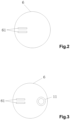
- the intelligent car lamplight control device further comprises a rain-fog detection sensor 6 used to automatically monitor the rain-fog state in an ambient environment and electrically connected to a digital input terminal of the main control MCU3, wherein two parallel and spaced metal sheets 61 are arranged on the rain-fog detection sensor 6; one metal sheet 61 is electrified, and when water is condensed between the two metal sheets 61, the two metal sheets 61 will be conductive with each other to cause a voltage change in the rain-fog detection sensor 6; the rain-fog detection sensor 6 can transmit a rain-fog state signal to the main control MCU3 after detecting the voltage change; and the main control MCU3 transmits a lamplight color switching control command to the lamplight main-control system 5 through the wireless transmitter 4 to control the lamplight main-control system 5 to switch white lamplight to yellow lamplight (turn on a fog lamp).
- a rain-fog detection sensor 6 used to automatically monitor the rain-fog state in an ambient environment and electrically connected
- the intelligent car lamplight control device in the above embodiments of the present invention is only exemplified by dividing above function modules.
- the above functions can be achieved by different function modules as required, that is, the internal structure of the system is divided into different function modules to achieve all or part of the functions described above.
- the intelligent car lamplight control device can monitor the light intensity in the ambient environment of the car and the car speed in real time to correspondingly control the car lamp according to these state data, and can correctly use the high beam and the low beam to fulfill intelligent control over the car lamp, thus avoiding violations or traffic accidents caused by improper use of the lamp, and guaranteeing the safety and reliability.
- the operating principle of rain-fog direction and control is as follows: When water is condensed on the two metal sheets, the voltage is transmitted from one metal sheet to the other metal sheet by means of the electrical conductivity of the water; when detecting the voltage, the rain-fog detection sensor circuit 71 transmits a signal to the MCU of the data processing circuit 75 for processing and then transmits the rain-fog state to the car lamp control module 8 every 20 seconds through the wireless transmitting circuit 74 by means of wireless encoding; and the yellow-white lamp PWM control circuit 81 switches white lamplight to yellow lamplight with higher power to penetrate through rain and fog.
- the principle of the rain-fog direction lies in that the rain-fog state is captured by means of the electrical conductivity of the water.
- the metal sheets are parallel, and are perpendicular to a driving direction to make sure that the condensate water on the metal sheets will not be blow away immediately during driving, which may otherwise cause a misjudgment.
- the rain and fog are determined by means of the electrical conductivity of the water, water condensation is guaranteed by the structural design of the parallel metal sheets, the rain-fog state and a sunny state are determined according to the on-off state of the metal sheets, and the color temperature of the lamplight is steplessly adjusted to 6500K from 2800K according to the rain-fog state.
- the operating principle of light intensity detection and control is as follows:
- the circuit provides a forward voltage for the photosensitive diode; when the light changes, the light intensity induced by the photosensitive diode is converted into the variable voltage signal input to an AD input port of the MCU of the data processing circuit 75 and then converted into a digital signal by the MCU, the MCU analyzes the state of ambient light through the acquired voltage signal and then transmits the state to the car lamp control module after encoding the state to be processed.
- the MCU provides data for the car lamp control module, and the car lamp control module controls a lamp control system to automatically turn on a lamp.
- the MCU determines the light state of an ambient environment in cooperation with a speed sensor; after the car leaves from the highway, the ambient light intensity sensor circuit transmits a signal to the car lamp control module when detecting a street lamp, and the car lamp control module automatically switches a high beam to a lower beam.
- a high beam is changed to be bright from being dim when an oncoming car appears; when detecting the oncoming car, the MCU transmits a data signal to the car lamp control module, and the car lamp control module changes the lamplight to the low beam to reduce the influence of long-range lamplight on drivers in passing-by cars, so that safe driving is achieved, and no influence will be caused to other car drivers.
- Whether light, reflected by an ambient wall, of the car is reflected light or ambient light is distinguished through circuit cooperation to reduce misjudgements.
- Lamps of the car are controlled by a 5KHz PWM; and when the reflected light is transmitted to the photosensitive diode, the circuit can restore a signal of the 5KHz PWM to determine whether the reflected light is lamplight of the car or the ambient light.
- the operating principle of speed detection and control is as follows:
- the 3D acceleration sensor chip is used, the MCU of the data processing circuit 75 reads data from the 3D acceleration sensor chip via the 12C communication port thereof.
- the MCU works out the speed of car during driving, the speed of the car in a static state, or a road gradient by means of the data.
- a driving speed or driving state is a necessary condition for turning on a car lamp.
- a 3D acceleration sensor sends information to the car lamp control module, the yellow-white lamp PWM control circuit automatically switches the low beam to the high beam to increase a visual range to guarantee safe driving.
- the yellow-white lamp PWM control circuit automatically adjusts a lamplight irradiation angle to make the road condition clear.
Landscapes
- Engineering & Computer Science (AREA)
- Computer Networks & Wireless Communication (AREA)
- Mechanical Engineering (AREA)
- Lighting Device Outwards From Vehicle And Optical Signal (AREA)
- Circuit Arrangement For Electric Light Sources In General (AREA)
Claims (9)
- Intelligente Fahrzeug-Lampenlicht-Steuervorrichtung, umfassend:einen Umgebungslicht-Intensitätssensor (1), der so konfiguriert ist, dass er automatisch eine Lichtintensität außerhalb eines Fahrzeugs überwacht;einen Geschwindigkeitssensor (2), der so konfiguriert ist, dass er eine Fahrgeschwindigkeit des Fahrzeugs erfasst;eine Hauptsteuereinheit MCU (3), die so konfiguriert ist, dass sie ein vom Umgebungslicht-Intensitätssensor übertragenes Lichtintensitätssignal und ein vom Geschwindigkeitssensor übertragenes Geschwindigkeitssignal erfasst,wobei die Hauptsteuereinheit MCU (3) so konfiguriert ist, dass, wenn durch Analyse festgestellt wird, dass ein Lichtintensitätswert im Lichtintensitätssignal kleiner als ein voreingestellter Wert ist oder von einem großen Wert zu einem kleinen Wert geändert wird und dann abwechselnd zwischen einem großen Wert und einem kleinen Wert wechselt, sie über einen drahtlosen Sender (4) einen Fahrzeuglampen-An-Aus-Steuerbefehl an ein Lampenlicht-Hauptsteuersystem (5) sendet, um so das Lampenlicht-Hauptsteuersystems (5) anzuweisen, eine Fahrzeuglampe anzuschalten;wobei die Hauptsteuereinheit MCU (3) so konfiguriert ist, dass, wenn erfasst wird, dass ein Geschwindigkeitswert im Geschwindigkeitssignal größer als ein voreingestellter Wert ist, sie über den drahtlosen Sender (4) einen Fernlicht/Abblendlicht-Umschaltsteuerbefehl an das Lampenlicht-Hauptsteuersystem (5) sendet, um so das Lampenlicht-Hauptsteuersystem (5) anzuweisen, ein Abblendlicht auf ein Fernlicht umzuschalten;dadurch gekennzeichnet, dass die Hauptsteuereinheit MCU (3) so konfiguriert ist, dass, wenn durch Analyse festgestellt wird, dass sich der Lichtintensitätswert von klein zu groß ändert oder sich abwechselnd zwischen einem großen Wert und einem kleinen Wert ändert und dass eine durchschnittliche Fahrgeschwindigkeit von hoch zu niedrig geändert wird, sie über den drahtlosen Sender (4) einen Fernlicht/Abblendlicht-Umschaltsteuerbefehl an das Lampenlicht-Hauptsteuersystem (5) sendet, um so das Lampenlicht-Hauptsteuersystem (5) anzuweisen, das Fernlicht auf das Abblendlicht umzuschalten; undwobei die intelligente Fahrzeug-Lampenlicht-Steuervorrichtung ferner umfasst:den drahtlosen Sender (4), der so konfiguriert ist, dass er die von der Hauptsteuereinheit MCU (3) gesendeten Steuerbefehle drahtlos an das Lampenlicht-Hauptsteuersystem (5) überträgt; unddas Lampenlicht-Hauptsteuersystem (5), das so konfiguriert ist, dass es die vom drahtlosen Sender (4) übertragenen Steuerbefehle empfängt und das Lampenlicht entsprechend den Steuerbefehlen steuert;wobei die Hauptsteuereinheit MCU (3) einen analogen Eingangsanschluss, der elektrisch mit dem Umgebungslicht-Intensitätssensor (1) verbunden ist, sowie einen 12C-Kommunikationsanschluss aufweist, der elektrisch mit dem Geschwindigkeitssensor (2) verbunden ist, und der drahtlose Sender (4) elektrisch mit der Hauptsteuereinheit MCU (3) verbunden ist und drahtlos mit dem Lampenlicht-Hauptsteuersystem (5) verbunden ist.
- Intelligente Fahrzeug-Lampenlicht-Steuervorrichtung nach Anspruch 1, wobei der Umgebungslicht-Intensitätssensor (1) eine lichtempfindliche Diode (11) umfasst, die so konfiguriert ist, dass sie eine induzierte Lichtintensität in ein Spannungssignal umwandelt.
- Intelligente Fahrzeug-Lampenlicht-Steuervorrichtung nach Anspruch 1, die ferner einen Regen-Nebel-Erkennungssensor (6) umfasst, der so konfiguriert ist, dass er einen Regen-Nebel-Zustand in einer Umgebung automatisch überwacht, und der elektrisch mit einem digitalen Eingangsanschluss der Hauptsteuereinheit MCU (3) verbunden ist, wobei zwei parallele und beabstandete Metallbleche (61) auf dem Regen-Nebel-Erkennungssensor (6) angeordnet sind; wobei eine der Metallplatten elektrifiziert ist und die beiden Metallplatten so konfiguriert sind, dass sie miteinander leitend sind, um eine Spannungsänderung im Regen-Nebel-Erkennungssensor (6) zu verursachen, wenn Wasser zwischen den beiden Metallplatten kondensiert; wobei der Regen-Nebel-Erkennungssensor (6) so konfiguriert ist, dass er ein Regen-Nebel-Zustandssignal an die Hauptsteuereinheit MCU (3) zu überträgt, nachdem die Spannungsänderung erfasst wurde; und wobei die Hauptsteuereinheit MCU (3) so konfiguriert ist, dass sie einen Befehl zum Umschalten der Lampenfarbe über den drahtlosen Sender (4) an das Lampenlicht-Hauptsteuersystem (5) sendet, um das Lampenlicht-Hauptsteuersystem (5) so zu steuern, dass es von weißem Lampenlicht auf gelbes Lampenlicht umschaltet.
- Intelligente Fahrzeug-Lampenlicht-Steuervorrichtung nach Anspruch 1, wobei der Geschwindigkeitssensor (2) einen 3D-Beschleunigungssensor IC enthält, der so konfiguriert ist, dass er ein Gefälle einer Straße, auf der das Auto fährt, erkennt, und bei der Bestimmung durch Analyse, dass ein Gefällewert der befahrenen Straße in einem vom Geschwindigkeitssensor (2) übertragenen Gefällesignal größer als ein voreingestellter Wert ist, die Hauptsteuereinheit MCU (3) so konfiguriert ist, dass sie einen Befehl zur Winkeleinstellung über den drahtlosen Sender (4) an das Lampenlicht-Hauptsteuersystem (5) sendet, um das Lampenlicht-Hauptsteuersystem (5) so zu steuern, dass es den Abstrahlwinkel der Fahrzeugbeleuchtung einstellt.
- Intelligente Fahrzeug-Lampenlicht-Steuervorrichtung nach Anspruch 1, wobei der drahtlose Sender (4) so konfiguriert ist, dass er Daten mittels eines Kommunikationsfrequenzbandes bei einer gemeinsamen drahtlosen Frequenz von 315 MHz bis 470 MHz überträgt.
- Intelligente Fahrzeug-Lampenlicht-Steuervorrichtung nach Anspruch 1, wobei das Lampenlicht-Hauptsteuersystem (5) ein linkes Lampenlicht-Steuersystem (51) und ein rechtes Lampenlicht-Steuersystem (52) umfasst, die in drahtloser Übertragungsverbindung mit dem drahtlosen Sender (4) stehen.
- Intelligente Fahrzeug-Lampenlicht-Steuervorrichtung nach Anspruch 6, wobei das linke Lampenlicht-Steuersystem (51) einen linken Lampenlicht-Datenprozessor (511), einen linken LED-Konstantstromquellen-Controller (512) und einen linken Lampenlicht-Drahtlosempfänger (513) umfasst, wobei der linke Lampenlicht-Datenprozessor (511) elektrisch mit dem linken Lampenlicht-Drahtlosempfänger (513) und dem linken LED-Konstantstromquellen-Controller (512) verbunden ist und der linke Lampenlicht-Drahtlosempfänger (513) in drahtloser Übertragungsverbindung mit dem drahtlosen Sender (4) steht.
- Intelligente Fahrzeug-Lampenlicht-Steuervorrichtung nach Anspruch 6, wobei das rechte Lampenlicht-Steuerungssystem (52) einen rechten Lampenlicht-Datenprozessor (521), einen rechten LED-Konstantstromquellen-Controller (522) und einen rechten Lampenlicht-Drahtlosempfänger (523) umfasst, wobei der rechte Lampenlicht-Datenprozessor (521) elektrisch mit dem rechten Lampenlicht-Drahtlosempfänger (523) und dem rechten LED-Konstantstromquellen-Controller (522) verbunden ist und der rechte Lampenlicht-Drahtlosempfänger (523) in drahtloser Übertragungsverbindung mit dem drahtlosen Sender (4) steht.
- Intelligente Fahrzeug-Lampenlicht-Steuervorrichtung nach Anspruch 1, wobei die Hauptsteuereinheit MCU (3) so konfiguriert ist, dass sie einen Lichtintensitätswert der Fahrzeuglampe mittels einer in der Hauptsteuereinheit MCU angeordneten Digital-Analog-Wandlerschaltung simuliert und den Lichtintensitätswert mit dem Lichtintensitätswert in dem vom Umgebungslicht-Intensitätssensor (1) übertragenen Lichtintensitätssignal vergleicht.
Applications Claiming Priority (2)
| Application Number | Priority Date | Filing Date | Title |
|---|---|---|---|
| CN202010046225.6A CN111169368B (zh) | 2020-01-16 | 2020-01-16 | 汽车灯光智能控制装置 |
| CN202020096646.5U CN211668338U (zh) | 2020-01-16 | 2020-01-16 | 一种玻璃钢风筒减震装置 |
Publications (2)
| Publication Number | Publication Date |
|---|---|
| EP3852499A1 EP3852499A1 (de) | 2021-07-21 |
| EP3852499B1 true EP3852499B1 (de) | 2025-01-08 |
Family
ID=76372378
Family Applications (1)
| Application Number | Title | Priority Date | Filing Date |
|---|---|---|---|
| EP20205495.3A Active EP3852499B1 (de) | 2020-01-16 | 2020-11-03 | Intelligente fahrzeuglampensteuervorrichtung |
Country Status (1)
| Country | Link |
|---|---|
| EP (1) | EP3852499B1 (de) |
Families Citing this family (7)
| Publication number | Priority date | Publication date | Assignee | Title |
|---|---|---|---|---|
| CN113784481A (zh) * | 2021-08-11 | 2021-12-10 | 深圳市智岩科技有限公司 | 车载灯光设备、方法、装置、设备、介质及车辆 |
| CN113891531A (zh) * | 2021-10-27 | 2022-01-04 | 杭州萧科节能科技有限公司 | 一种can智慧前照灯控制模块 |
| CN115399607A (zh) * | 2022-09-20 | 2022-11-29 | 重庆亿海腾模型科技有限公司 | 汽车模型尾灯360度旋转展示方法 |
| CN115734419B (zh) * | 2022-12-03 | 2023-06-23 | 广州汗马电子科技有限公司 | 一种汽车灯具亮度自动调节方法、系统、设备及存储介质 |
| CN117111516B (zh) * | 2023-09-07 | 2024-04-02 | 江苏日兴汽车配件有限公司 | 一种汽车室内灯智能控制系统及方法 |
| CN118510135A (zh) * | 2024-05-21 | 2024-08-16 | 广州威博智能科技股份有限公司 | 一种无线遥控控制的摩托车四路led车灯驱动电路 |
| CN119370012A (zh) * | 2024-12-04 | 2025-01-28 | 奇瑞汽车股份有限公司 | 一种可变模式近光灯控制系统及方法 |
Family Cites Families (4)
| Publication number | Priority date | Publication date | Assignee | Title |
|---|---|---|---|---|
| US6049171A (en) * | 1998-09-18 | 2000-04-11 | Gentex Corporation | Continuously variable headlamp control |
| US9586516B2 (en) * | 2014-02-28 | 2017-03-07 | Gentex Corporation | Headlight level control with residential detection mode |
| CN108189750A (zh) * | 2016-12-08 | 2018-06-22 | 湖南三维精工打印科技有限公司 | 无线双向汽车夜间会车远光灯智能控制系统 |
| US10486586B1 (en) * | 2018-08-20 | 2019-11-26 | Ford Global Technologies, Llc | Control of vehicle headlights based on weather conditions |
-
2020
- 2020-11-03 EP EP20205495.3A patent/EP3852499B1/de active Active
Also Published As
| Publication number | Publication date |
|---|---|
| EP3852499A1 (de) | 2021-07-21 |
Similar Documents
| Publication | Publication Date | Title |
|---|---|---|
| EP3852499B1 (de) | Intelligente fahrzeuglampensteuervorrichtung | |
| US11066007B1 (en) | Intelligent car lamplight control device | |
| KR102002019B1 (ko) | 도로 상황에 따라 가로등의 점등구간을 조절하는 도로 조명 제어시스템 | |
| KR101044224B1 (ko) | 차량감응 하이브리드가로등 제어 시스템 및 방법 | |
| CN105235583A (zh) | 一种汽车车灯光自动警示系统及控制方法 | |
| CN112406687A (zh) | 一种“人-车-路”协同的可编程矩阵式前照灯系统及方法 | |
| WO2018232906A1 (zh) | 一种智能路灯监控方法及装置 | |
| CN110316045B (zh) | 安全行车提醒设备、智能行车系统及方法 | |
| CN103273872A (zh) | 一种汽车远近光自动切换装置 | |
| US20250056672A1 (en) | Adaptive street lighting system | |
| CN103507697A (zh) | 车灯控制系统 | |
| CN105101563A (zh) | 一种汽车隧道安全行驶照明系统及照明控制方法 | |
| CN107613618A (zh) | 汽车远近光灯控制系统及方法 | |
| CN105946696A (zh) | 基于可见光通信技术的汽车远近光灯控制系统及方法 | |
| KR102004351B1 (ko) | 차량감응식 터널 조명 제어장치 | |
| CN205149636U (zh) | 一种夜间会车远近光灯自动转换装置 | |
| CN103929867A (zh) | 照明灯控制方法 | |
| CN115443494A (zh) | 用于自动确定交通信号设施的显示状态的方法和系统 | |
| CN212086550U (zh) | 汽车灯光控制装置 | |
| CN103228086A (zh) | 一种按需道路照明控制系统 | |
| CN117227619A (zh) | 一种实现智能转弯辅助照明的方法 | |
| CN206568968U (zh) | 一种自动调节车辆前照灯远近光系统 | |
| KR102273977B1 (ko) | 차량용 전조등의 색상 제어 시스템 | |
| CN205440107U (zh) | 一种汽车远近光灯自动切换的装置 | |
| CN211772994U (zh) | 一种可实现无线智能斑马线警示系统 |
Legal Events
| Date | Code | Title | Description |
|---|---|---|---|
| PUAI | Public reference made under article 153(3) epc to a published international application that has entered the european phase |
Free format text: ORIGINAL CODE: 0009012 |
|
| STAA | Information on the status of an ep patent application or granted ep patent |
Free format text: STATUS: THE APPLICATION HAS BEEN PUBLISHED |
|
| AK | Designated contracting states |
Kind code of ref document: A1 Designated state(s): AL AT BE BG CH CY CZ DE DK EE ES FI FR GB GR HR HU IE IS IT LI LT LU LV MC MK MT NL NO PL PT RO RS SE SI SK SM TR |
|
| STAA | Information on the status of an ep patent application or granted ep patent |
Free format text: STATUS: REQUEST FOR EXAMINATION WAS MADE |
|
| 17P | Request for examination filed |
Effective date: 20210727 |
|
| RBV | Designated contracting states (corrected) |
Designated state(s): AL AT BE BG CH CY CZ DE DK EE ES FI FR GB GR HR HU IE IS IT LI LT LU LV MC MK MT NL NO PL PT RO RS SE SI SK SM TR |
|
| RIC1 | Information provided on ipc code assigned before grant |
Ipc: B60Q 1/14 20060101ALI20221227BHEP Ipc: H05B 47/105 20200101ALI20221227BHEP Ipc: H05B 47/11 20200101AFI20221227BHEP |
|
| STAA | Information on the status of an ep patent application or granted ep patent |
Free format text: STATUS: EXAMINATION IS IN PROGRESS |
|
| 17Q | First examination report despatched |
Effective date: 20240228 |
|
| GRAP | Despatch of communication of intention to grant a patent |
Free format text: ORIGINAL CODE: EPIDOSNIGR1 |
|
| STAA | Information on the status of an ep patent application or granted ep patent |
Free format text: STATUS: GRANT OF PATENT IS INTENDED |
|
| GRAS | Grant fee paid |
Free format text: ORIGINAL CODE: EPIDOSNIGR3 |
|
| INTG | Intention to grant announced |
Effective date: 20240903 |
|
| P01 | Opt-out of the competence of the unified patent court (upc) registered |
Free format text: CASE NUMBER: APP_52122/2024 Effective date: 20240917 |
|
| GRAA | (expected) grant |
Free format text: ORIGINAL CODE: 0009210 |
|
| STAA | Information on the status of an ep patent application or granted ep patent |
Free format text: STATUS: THE PATENT HAS BEEN GRANTED |
|
| AK | Designated contracting states |
Kind code of ref document: B1 Designated state(s): AL AT BE BG CH CY CZ DE DK EE ES FI FR GB GR HR HU IE IS IT LI LT LU LV MC MK MT NL NO PL PT RO RS SE SI SK SM TR |
|
| REG | Reference to a national code |
Ref country code: GB Ref legal event code: FG4D |
|
| REG | Reference to a national code |
Ref country code: CH Ref legal event code: EP |
|
| REG | Reference to a national code |
Ref country code: DE Ref legal event code: R096 Ref document number: 602020044430 Country of ref document: DE |
|
| REG | Reference to a national code |
Ref country code: IE Ref legal event code: FG4D |
|
| REG | Reference to a national code |
Ref country code: LT Ref legal event code: MG9D |
|
| REG | Reference to a national code |
Ref country code: NL Ref legal event code: MP Effective date: 20250108 |
|
| REG | Reference to a national code |
Ref country code: AT Ref legal event code: MK05 Ref document number: 1759160 Country of ref document: AT Kind code of ref document: T Effective date: 20250108 |
|
| PG25 | Lapsed in a contracting state [announced via postgrant information from national office to epo] |
Ref country code: NL Free format text: LAPSE BECAUSE OF FAILURE TO SUBMIT A TRANSLATION OF THE DESCRIPTION OR TO PAY THE FEE WITHIN THE PRESCRIBED TIME-LIMIT Effective date: 20250108 |
|
| PG25 | Lapsed in a contracting state [announced via postgrant information from national office to epo] |
Ref country code: RS Free format text: LAPSE BECAUSE OF FAILURE TO SUBMIT A TRANSLATION OF THE DESCRIPTION OR TO PAY THE FEE WITHIN THE PRESCRIBED TIME-LIMIT Effective date: 20250408 |
|
| PG25 | Lapsed in a contracting state [announced via postgrant information from national office to epo] |
Ref country code: FI Free format text: LAPSE BECAUSE OF FAILURE TO SUBMIT A TRANSLATION OF THE DESCRIPTION OR TO PAY THE FEE WITHIN THE PRESCRIBED TIME-LIMIT Effective date: 20250108 |
|
| PG25 | Lapsed in a contracting state [announced via postgrant information from national office to epo] |
Ref country code: PL Free format text: LAPSE BECAUSE OF FAILURE TO SUBMIT A TRANSLATION OF THE DESCRIPTION OR TO PAY THE FEE WITHIN THE PRESCRIBED TIME-LIMIT Effective date: 20250108 |
|
| PG25 | Lapsed in a contracting state [announced via postgrant information from national office to epo] |
Ref country code: ES Free format text: LAPSE BECAUSE OF FAILURE TO SUBMIT A TRANSLATION OF THE DESCRIPTION OR TO PAY THE FEE WITHIN THE PRESCRIBED TIME-LIMIT Effective date: 20250108 |
|
| PG25 | Lapsed in a contracting state [announced via postgrant information from national office to epo] |
Ref country code: IS Free format text: LAPSE BECAUSE OF FAILURE TO SUBMIT A TRANSLATION OF THE DESCRIPTION OR TO PAY THE FEE WITHIN THE PRESCRIBED TIME-LIMIT Effective date: 20250508 Ref country code: NO Free format text: LAPSE BECAUSE OF FAILURE TO SUBMIT A TRANSLATION OF THE DESCRIPTION OR TO PAY THE FEE WITHIN THE PRESCRIBED TIME-LIMIT Effective date: 20250408 |
|
| PG25 | Lapsed in a contracting state [announced via postgrant information from national office to epo] |
Ref country code: HR Free format text: LAPSE BECAUSE OF FAILURE TO SUBMIT A TRANSLATION OF THE DESCRIPTION OR TO PAY THE FEE WITHIN THE PRESCRIBED TIME-LIMIT Effective date: 20250108 |
|
| PG25 | Lapsed in a contracting state [announced via postgrant information from national office to epo] |
Ref country code: PT Free format text: LAPSE BECAUSE OF FAILURE TO SUBMIT A TRANSLATION OF THE DESCRIPTION OR TO PAY THE FEE WITHIN THE PRESCRIBED TIME-LIMIT Effective date: 20250508 Ref country code: LV Free format text: LAPSE BECAUSE OF FAILURE TO SUBMIT A TRANSLATION OF THE DESCRIPTION OR TO PAY THE FEE WITHIN THE PRESCRIBED TIME-LIMIT Effective date: 20250108 |
|
| PG25 | Lapsed in a contracting state [announced via postgrant information from national office to epo] |
Ref country code: GR Free format text: LAPSE BECAUSE OF FAILURE TO SUBMIT A TRANSLATION OF THE DESCRIPTION OR TO PAY THE FEE WITHIN THE PRESCRIBED TIME-LIMIT Effective date: 20250409 Ref country code: BG Free format text: LAPSE BECAUSE OF FAILURE TO SUBMIT A TRANSLATION OF THE DESCRIPTION OR TO PAY THE FEE WITHIN THE PRESCRIBED TIME-LIMIT Effective date: 20250108 |
|
| PG25 | Lapsed in a contracting state [announced via postgrant information from national office to epo] |
Ref country code: AT Free format text: LAPSE BECAUSE OF FAILURE TO SUBMIT A TRANSLATION OF THE DESCRIPTION OR TO PAY THE FEE WITHIN THE PRESCRIBED TIME-LIMIT Effective date: 20250108 |
|
| PG25 | Lapsed in a contracting state [announced via postgrant information from national office to epo] |
Ref country code: SE Free format text: LAPSE BECAUSE OF FAILURE TO SUBMIT A TRANSLATION OF THE DESCRIPTION OR TO PAY THE FEE WITHIN THE PRESCRIBED TIME-LIMIT Effective date: 20250108 |
|
| PG25 | Lapsed in a contracting state [announced via postgrant information from national office to epo] |
Ref country code: SM Free format text: LAPSE BECAUSE OF FAILURE TO SUBMIT A TRANSLATION OF THE DESCRIPTION OR TO PAY THE FEE WITHIN THE PRESCRIBED TIME-LIMIT Effective date: 20250108 |
|
| REG | Reference to a national code |
Ref country code: DE Ref legal event code: R097 Ref document number: 602020044430 Country of ref document: DE |
|
| PG25 | Lapsed in a contracting state [announced via postgrant information from national office to epo] |
Ref country code: DK Free format text: LAPSE BECAUSE OF FAILURE TO SUBMIT A TRANSLATION OF THE DESCRIPTION OR TO PAY THE FEE WITHIN THE PRESCRIBED TIME-LIMIT Effective date: 20250108 |
|
| PG25 | Lapsed in a contracting state [announced via postgrant information from national office to epo] |
Ref country code: EE Free format text: LAPSE BECAUSE OF FAILURE TO SUBMIT A TRANSLATION OF THE DESCRIPTION OR TO PAY THE FEE WITHIN THE PRESCRIBED TIME-LIMIT Effective date: 20250108 Ref country code: CZ Free format text: LAPSE BECAUSE OF FAILURE TO SUBMIT A TRANSLATION OF THE DESCRIPTION OR TO PAY THE FEE WITHIN THE PRESCRIBED TIME-LIMIT Effective date: 20250108 |
|
| PG25 | Lapsed in a contracting state [announced via postgrant information from national office to epo] |
Ref country code: RO Free format text: LAPSE BECAUSE OF FAILURE TO SUBMIT A TRANSLATION OF THE DESCRIPTION OR TO PAY THE FEE WITHIN THE PRESCRIBED TIME-LIMIT Effective date: 20250108 |
|
| PG25 | Lapsed in a contracting state [announced via postgrant information from national office to epo] |
Ref country code: SK Free format text: LAPSE BECAUSE OF FAILURE TO SUBMIT A TRANSLATION OF THE DESCRIPTION OR TO PAY THE FEE WITHIN THE PRESCRIBED TIME-LIMIT Effective date: 20250108 |
|
| PLBE | No opposition filed within time limit |
Free format text: ORIGINAL CODE: 0009261 |
|
| STAA | Information on the status of an ep patent application or granted ep patent |
Free format text: STATUS: NO OPPOSITION FILED WITHIN TIME LIMIT |
|
| 26N | No opposition filed |
Effective date: 20251009 |
|
| PG25 | Lapsed in a contracting state [announced via postgrant information from national office to epo] |
Ref country code: IT Free format text: LAPSE BECAUSE OF FAILURE TO SUBMIT A TRANSLATION OF THE DESCRIPTION OR TO PAY THE FEE WITHIN THE PRESCRIBED TIME-LIMIT Effective date: 20250108 |