EP3852249B1 - Geformter motor - Google Patents
Geformter motor Download PDFInfo
- Publication number
- EP3852249B1 EP3852249B1 EP19860332.6A EP19860332A EP3852249B1 EP 3852249 B1 EP3852249 B1 EP 3852249B1 EP 19860332 A EP19860332 A EP 19860332A EP 3852249 B1 EP3852249 B1 EP 3852249B1
- Authority
- EP
- European Patent Office
- Prior art keywords
- opening
- mold resin
- molded motor
- metal member
- lead bush
- Prior art date
- Legal status (The legal status is an assumption and is not a legal conclusion. Google has not performed a legal analysis and makes no representation as to the accuracy of the status listed.)
- Active
Links
Images


Classifications
-
- H—ELECTRICITY
- H02—GENERATION; CONVERSION OR DISTRIBUTION OF ELECTRIC POWER
- H02K—DYNAMO-ELECTRIC MACHINES
- H02K5/00—Casings; Enclosures; Supports
- H02K5/04—Casings or enclosures characterised by the shape, form or construction thereof
- H02K5/15—Mounting arrangements for bearing-shields or end plates
-
- H—ELECTRICITY
- H02—GENERATION; CONVERSION OR DISTRIBUTION OF ELECTRIC POWER
- H02K—DYNAMO-ELECTRIC MACHINES
- H02K5/00—Casings; Enclosures; Supports
- H02K5/04—Casings or enclosures characterised by the shape, form or construction thereof
- H02K5/08—Insulating casings
-
- H—ELECTRICITY
- H02—GENERATION; CONVERSION OR DISTRIBUTION OF ELECTRIC POWER
- H02K—DYNAMO-ELECTRIC MACHINES
- H02K5/00—Casings; Enclosures; Supports
- H02K5/04—Casings or enclosures characterised by the shape, form or construction thereof
- H02K5/16—Means for supporting bearings, e.g. insulating supports or means for fitting bearings in the bearing-shields
- H02K5/173—Means for supporting bearings, e.g. insulating supports or means for fitting bearings in the bearing-shields using bearings with rolling contact, e.g. ball bearings
- H02K5/1732—Means for supporting bearings, e.g. insulating supports or means for fitting bearings in the bearing-shields using bearings with rolling contact, e.g. ball bearings radially supporting the rotary shaft at both ends of the rotor
-
- H—ELECTRICITY
- H02—GENERATION; CONVERSION OR DISTRIBUTION OF ELECTRIC POWER
- H02K—DYNAMO-ELECTRIC MACHINES
- H02K5/00—Casings; Enclosures; Supports
- H02K5/04—Casings or enclosures characterised by the shape, form or construction thereof
- H02K5/22—Auxiliary parts of casings not covered by groups H02K5/06-H02K5/20, e.g. shaped to form connection boxes or terminal boxes
- H02K5/225—Terminal boxes or connection arrangements
Definitions
- a molded motor in which a stator is covered with a mold resin is known (Patent Literature 1 (PTL 1)).
- PTL 1 Patent Literature 1
- a molded motor includes a stator, a rotor disposed inside the stator, a mold resin that covers the stator, and a printed circuit board to which coils included in the stator are connected.
- a plurality of lead wires connected to a printed circuit board are drawn out of the motor via a lead bush attached to an opening of a side wall portion made of a mold resin.
- JP 6 202173 B2 Another example of such a motor is disclosed in JP 6 202173 B2 .
- the wire diameter of the coil included in the stator is large (for example, ⁇ 0.3 mm or more), so that the coil is less likely to be disconnected even if the coil abnormally heats up. For this reason, there is a high possibility that a layer short circuit will occur in a high-output molded motor.
- the present disclosure has been made in order to solve such a problem, and an object of the present disclosure is to provide a molded motor that can suppress fire from spouting from the place where the lead bush in the mold resin is attached even when ignition occurs inside the mold resin due to abnormal heat generation or the like of the coil included in the stator.
- one aspect of the molded motor according to the present disclosure includes: a stator that includes a stator core and a coil wound around the stator core via an insulator; a rotor that is arranged to face the stator and includes a rotor core and a rotary shaft; a mold resin that includes a first opening and covers the stator; and a lead bush that is attached to the first opening and includes an insertion through-hole for drawing out an electric wire, wherein the lead bush includes a metal member including a second opening for drawing out the electric wire, the second opening being smaller than the first opening and larger than the insertion through-hole.
- another aspect of the molded motor according to the present disclosure includes: a stator that includes a stator core and a coil wound around the stator core via an insulator; a rotor that is arranged to face the stator and includes a rotor core and a rotary shaft; a mold resin that includes a first opening and covers the stator; and a lead bush made of a ceramic that is attached to the first opening and has an insertion through-hole for drawing out an electric wire, wherein the insertion through-hole is smaller than the first opening.
- each drawing is a schematic view and is not necessarily strictly illustrated. It should be noted that in each drawing, the same reference numerals are given to substantially the same configurations, and overlapping description will be omitted or simplified.
- FIG. 1 is a perspective view of molded motor 1 according to Embodiment 1.
- FIG. 2 is an exploded perspective view of molded motor 1.
- FIG. 3 is a cross-sectional view of molded motor 1.
- FIG. 4 is a cross-sectional view of molded motor 1 taken along line IV-IV in FIG. 34. It should be noted that in FIGS.
- a direction in which rotary shaft 21 included in rotor 20 extends is defined as axial direction X
- a direction that extends from shaft center C about shaft center C of rotary shaft 21 is defined as radial direction Y
- a circumferential direction centered on shaft center C is defined as circumferential direction Z.
- hatching is omitted for convenience of illustration of the core portion of stator core 11 and the core portion of rotor core 22 in order to make the drawing easy to see.
- molded motor 1 includes stator 10, rotor 20 arranged to face stator 10, mold resin 30 covering stator 10, and lead bush 40 attached to mold resin 30.
- Molded motor 1 further includes first bearing 51 and second bearing 52, first bracket 61 and second bracket 62, first metal cover 71 and second metal cover 72, and circuit board 80.
- mold resin 30 In molded motor 1, mold resin 30, first bracket 61, second bracket 62, and first metal cover 71 configure the outer shell of molded motor 1.
- Molded motor 1 in the present embodiment is a brushless motor without using a brush.
- molded motor 1 in the present embodiment is an inner rotor type motor in which rotor 20 is arranged inside stator 10. It should be noted that the present disclosure can also be applied to an outer rotor type motor in which the rotor is arranged outside the stator.
- Stator 10 (stational element) is arranged so as to surround rotor 20 via a small air gap between stator 10 and rotor 20.
- Stator 10 includes stator core 11, coil 12, and insulator 13.
- Stator core 11 is an annular iron core that generates a magnetic force for rotating rotor 20.
- stator core 11 is, for example, a stacked body in which a plurality of electromagnetic steel plates are stacked in the longitudinal direction (axial direction X) of rotary shaft 21 included in rotor 20. It should be noted that stator core 11 is not limited to the stacked body and may be a bulk body made of a magnetic material.
- stator core 11 includes yoke 11a formed in an annular shape so as to surround rotor 20, and a plurality of teeth 11b protruding from yoke 11a toward rotary shaft 21 in a convex shape.
- stator core 11 is provided with twelve teeth 11b.
- Yoke 11a is a back yoke formed outside each tooth 11b.
- yoke 11a is formed in an annular shape about shaft center C.
- the plurality of teeth 11b are arranged at equal intervals in circumferential direction Z, respectively, while forming slots 14 which are openings between them.
- extending portions 11b1 extending on both sides in circumferential direction Z are formed at the extending tip portions where each tooth 11b is extended.
- the inner peripheral surface located at the tip portion of tooth 11b including this extending portion 11b1 serves as a magnetic pole surface facing the outer peripheral surface of rotor 20. It should be noted that in two adjacent teeth 11b, a gap (slot opening) exists between extending portion 11b1 of one tooth 11b and extending portion 11b1 of the other tooth 11b.
- Coil 12 is a winding coil wound around stator core 11 via insulator 13. Specifically, as shown in FIG. 4 , coil 12 is wound around each of the plurality of teeth 11b included in stator core 11. In addition, as shown in FIG. 3 , each coil 12 includes coil end 12a protruding from stator core 11 to both sides of stator core 11 along the longitudinal direction (axial direction X) of rotary shaft 21. That is, coil end 12a is a portion of coil 12 that protrudes and sticks out from stator core 11 in axial direction X. It should be noted that 12 coils 12 are used in the present embodiment. Therefore, the number of slots of molded motor 1 is 12.
- circuit board 80 ends of each phase of coil 12 are connected by winding connection portions included in circuit board 80.
- pattern wirings for electrically connecting the plurality of coils 12 for each of the U-phase, V-phase, and W-phase are formed on circuit board 80, and the ends of coils 12 for each phase are electrically connected with pattern wirings of circuit board 80 by solder or the like.
- circuit board 80 includes an opening through which rotary shaft 21 is loosely inserted at a center portion, and has, for example, an annular shape (a donut shape), a fan shape (an arc shape), a C shape, or the like.
- each phase of coil 12 may be configured to use a connecting member made of a conductive material in addition to the configuration using the circuit board. It should be noted that the present disclosure can be applied to any structure as long as the lead wire is inserted inside the enclosure of the motor regardless of the specifications of the motor.
- insulator 13 is an insulating frame that covers stator core 11. Specifically, insulator 13 covers teeth 11b included in stator core 11, and is provided for each tooth 11b. Insulator 13 is made of, for example, an insulating resin material such as PBT.
- first metal cover 71 or second metal cover 72 may be provided, but by providing both first metal cover 71 and second metal cover 72, it is possible to reliably prevent fire from spouting to the outside of molded motor 1.
- molded motor 1 of the present embodiment even if ignition occurs inside mold resin 30 due to abnormal heat generation of the coil or the like, it is possible to suppress fire from spouting from the place where lead bush 40 is attached in mold resin 30 to the outside.
- metal member 41 is fixed to lead bush 40 so as to be positioned outside mold resin 30 in the present embodiment, but it is not limited thereto.
- metal member 41 may be fixed to lead bush 40 so as to be positioned inside mold resin 30, or may be fixed to lead bush 40 so as to be positioned at first opening 30a (middle side) formed in mold resin 30.
- positioning portion 41b included in metal member 41A functions as a fall prevention structure for metal member 41A. With this, it is possible to further suppress fire from spouting from first opening 30a.
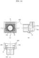
- metal member 41 of lead bush 40 is configured by one metal plate, but in molded motor 2 according to the present embodiment as shown in FIGS. 12 and 13 , metal member 41 included in lead bush 40B is configured by a plurality of metal plates. It should be noted that in the description of Embodiment 2 and the subsequent embodiments, the same components as those in Embodiment 1 will be designated by the same reference numerals and the description of each component will be incorporated.
- metal member 41 is configured by a plurality of metal plates covering first opening 30a formed in mold resin 30.
- the plurality of metal plates configuring metal member 41 are arranged so as to overlap each other. More specifically, the plurality of metal plates are arranged such that second opening 41a included in each of the plurality of metal plates overlap each other. It should be noted that metal member 41 is configured by two metal plates in the present embodiment.
- metal member 41 is configured by a plurality of metal plates in the present embodiment. That is, first opening 30a formed in mold resin 30 is closed by the metal plate having a double structure. With this, it is possible to further suppress fire from spouting from first opening 30a formed in mold resin 30 to the outside of mold resin 30.
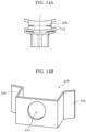
- both of the two metal plates configuring metal member 41 are flat, but the present invention is not limited thereto.
- one of the two metal plates configuring metal member 41 may be curved as in lead bush 40B shown in FIG. 14A . It should be noted that both of the two metal plates configuring metal member 41 may be curved.
- metal member 41B may have a positioning portion (hook portion) 41b for attaching metal member 41B to mold resin 30 similar to metal member 41A shown in FIG. 10 . That is, metal member 41B may have a fall prevention structure.
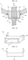
- FIG. 15 is a cross-sectional view showing the peripheral structure of mold resin 30 and lead bush 40C in molded motor 3 according to Embodiment 3.
- FIG. 16 is a perspective view of metal member 41C included in lead bush 40C used in molded motor 3
- FIG. 17 is a top view of metal member 41C.
- lead bush 40C is a connector type, and includes protruding portion 41c that protrudes outward from the side wall portion of mold resin 30.
- Insertion through-hole 40a formed in lead bush 40C in the present embodiment is a small hole for preventing electric wire 90 from moving.
- three electric wires 90 are inserted through lead bush 40C, three insertion through-holes 40a are provided. Electric wire 90 is inserted into each of insertion through-holes 40a. Electric wire 90 inserted into insertion through-hole 40a is held by lead bush 40C.
- metal member 41C of lead bush 40C in the present embodiment is a metal cover that covers the outer surface of protruding portion 41c included in lead bush 40C.
- the metal cover is made of, for example, iron or the like.
- Metal member 41C which is a metal cover, includes second opening 41a. As shown in FIGS. 16 and 17 , the shape of second opening 41a is rectangular in a front view seen in radial direction Y. Also in the present embodiment, second opening 41a is smaller than first opening 30a formed in mold resin 30 and larger than each insertion through-hole 40a included in lead bush 40C. Specifically, second opening 41a surrounds three insertion through-holes 40a included in lead bush 40C.
- positioning portion 41b included in metal member 41C functions as a fall prevention structure for metal member 41C, and thus it is possible to further suppress fire from spouting from first opening 30a.
- molded motor 3 has the same configuration as the molded motors 1 and 2 according to Embodiments 1 and 2 described above except for the above-described features.
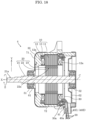
- FIG. 18 is a cross-sectional view of molded motor 4 according to Embodiment 4.
- FIG. 19 is a diagram showing molded motor 4 according to Embodiment 4 with lead bush 40D removed.
- FIGS. 20 and 21 are cross-sectional views showing the peripheral structure of mold resin 30 and lead bushes 40D and 40E in molded motor 4 according to Embodiment 4.
- molded motor 4 includes stator 10, rotor 20 arranged to face stator 10, mold resin 30 covering stator 10, and lead bush 40D made of a ceramic.
- Stator 10 includes stator core 11, coil 12, and insulator 13.
- Coil 12 is a winding coil wound around stator core 11 via insulator 13.
- Mold resin 30 includes first opening 30a. Lead bush 40D is attached to this first opening 30a.
- Lead bush 40D is a drawer portion for drawing out electric wire 90.
- Lead bush 40D is formed with an insertion through-hole 40a for drawing out electric wire 90.
- Insertion through-hole 40a is smaller than first opening 30a. That is, when insertion through-hole 40a formed in lead bush 40D is viewed from the front, that is, in radial direction Y intersecting with rotary shaft 21, the opening area of insertion through-hole 40a is smaller than the opening area of first opening 30a formed in mold resin 30.
- the entire circumference of the opening edge of insertion through-hole 40a formed in lead bush 40D is located inside the entire circumference of the opening edge of first opening 30a formed in mold resin 30.
- the opening width of first opening 30a is W11 and the opening width of insertion through-hole 40a is W13 as shown in FIG. 20 , the relationship of W13 ⁇ W11 is satisfied.
- lead bush 40E includes inner opening 40c and outer opening 40d for drawing out electric wires 90 as shown in FIG. 21 .
- Inner opening 40c is located inside molded motor 4 in lead bush 40E attached to mold resin 30.
- Outer opening 40d is located outside molded motor 4 in lead bush 40E attached to mold resin 30.
- insertion through-hole 40a formed in lead bush 40E includes inner opening 40c that is open to the inside of molded motor 4, that is, the rotary shaft 21 side, and outer opening 40d that is open to the outside of molded motor 4, that is, the opposite side to the side where rotary shaft 21 is located.
Landscapes
- Engineering & Computer Science (AREA)
- Power Engineering (AREA)
- Motor Or Generator Frames (AREA)
Claims (8)
- Ein gegossener Motor (1, 2, 3), umfassend:einen Stator (10), der einen Statorkern (11) und eine Spule (12) enthält, die über einen Isolator (13) um den Statorkern (11) gewickelt ist;einen Rotor (20), der so angeordnet ist, dass er dem Stator (10) gegenüberliegt, und einen Rotorkern (22) und eine Drehwelle (21) umfasst;ein Formharz (30), das eine erste Öffnung (30a) umfasst und den Stator (10) bedeckt; undeine Führungsbuchse (40, 40A, 40B, 40C, 40D, 40E), die an der ersten Öffnung (30a) befestigt ist und ein Einsteckdurchgangsloch (40a) zum Herausziehen eines elektrischen Drahtes (90) umfasst, dadurch gekennzeichnet, dassdie Führungsbuchse (40, 40A, 40B, 40C, 40D, 40E) ein Metallteil (41, 41A, 41B, 41C) mit einer zweiten Öffnung (41a) zum Herausziehen des elektrischen Drahtes (90) umfasst, wobei die zweite Öffnung (41a) kleiner als die erste Öffnung (30a) und größer als das Einsteckdurchgangsloch (40a) ist, wobei sich das Einsteckdurchgangsloch (40a) durch die zweite Öffnung (41a) erstreckt; wobeieine Außenform des Metallteils (41, 41A, 41B, 41C) die erste Öffnung (30a) abdeckt.
- Der gegossene Motor (1, 2) gemäß Anspruch 1, wobei
das Metallteil (41, 41A, 41B) in die Führungsbuchse (40, 40A, 40B, 40D, 40E) eingebettet ist. - Der gegossene Motor (1, 2, 3) gemäß Anspruch 2, wobei
das Metallteil (41, 41A, 41B, 41C) so angeordnet ist, dass eine Außenform des Metallteils (41, 41A, 41B, 41C) die erste Öffnung (30a) in einer Richtung abdeckt, die eine Längsrichtung der Drehwelle (21) schneidet. - Der gegossene Motor (2) gemäß Anspruch 3, wobeidas Metallteil (41) mehrere Metallplatten umfasst, die die erste Öffnung (30a) abdecken, unddie mehreren Metallplatten so angeordnet sind, dass die zweite Öffnung (41a), die in jeder der mehreren Metallplatten enthalten ist, sich gegenseitig überlappen.
- Der gegossene Motor (3) nach Anspruch 1, wobeidie Führungsbuchse (40C) einen vorstehenden Abschnitt (41c) aufweist, der das Einsteckdurchgangsloch (41a) aufweist und nach außen vorsteht, unddas Metallteil (41C) eine Metallabdeckung ist, die eine Außenfläche des vorstehenden Abschnitts (41c) abdeckt.
- Der gegossene Motor (1, 2, 3) nach einem der Ansprüche 1 bis 5, wobei
das Metallteil (41A, 41B, 41C) einen Positionierungsabschnitt (41b) zum Befestigen des Metallteils (41A, 41B, 41C) an dem Formharz (30) umfasst. - Der gegossene Motor (1, 2, 3, 4) gemäß einem der Ansprüche 1 bis 6, wobei
der Drahtdurchmesser der Spule (12) φ0,3 mm oder mehr beträgt. - Der gegossene Motor (1, 2, 3, 4) gemäß einem der Ansprüche 1 bis 8, wobeidie Spule (12) Spulenenden (12a) aufweist, die entlang einer Längsrichtung der Drehwelle (21) aus dem Statorkern (11) zu beiden Seiten des Statorkerns (11) herausragen, undjedes der Spulenenden (12a) mit einer Metallabdeckung (71, 72) bedeckt ist, die entlang einer Umfangsrichtung des Formharzes (30) vorgesehen ist.
Applications Claiming Priority (2)
| Application Number | Priority Date | Filing Date | Title |
|---|---|---|---|
| JP2018170912 | 2018-09-12 | ||
| PCT/JP2019/027258 WO2020054199A1 (ja) | 2018-09-12 | 2019-07-10 | モールドモータ |
Publications (4)
| Publication Number | Publication Date |
|---|---|
| EP3852249A1 EP3852249A1 (de) | 2021-07-21 |
| EP3852249A4 EP3852249A4 (de) | 2021-11-03 |
| EP3852249C0 EP3852249C0 (de) | 2025-07-02 |
| EP3852249B1 true EP3852249B1 (de) | 2025-07-02 |
Family
ID=69777112
Family Applications (1)
| Application Number | Title | Priority Date | Filing Date |
|---|---|---|---|
| EP19860332.6A Active EP3852249B1 (de) | 2018-09-12 | 2019-07-10 | Geformter motor |
Country Status (4)
| Country | Link |
|---|---|
| EP (1) | EP3852249B1 (de) |
| JP (1) | JP7445898B2 (de) |
| CN (1) | CN112166543B (de) |
| WO (1) | WO2020054199A1 (de) |
Families Citing this family (1)
| Publication number | Priority date | Publication date | Assignee | Title |
|---|---|---|---|---|
| WO2023231498A1 (zh) * | 2022-06-01 | 2023-12-07 | 威灵(芜湖)电机制造有限公司 | 电机及电器设备 |
Family Cites Families (21)
| Publication number | Priority date | Publication date | Assignee | Title |
|---|---|---|---|---|
| GB801224A (en) * | 1955-06-23 | 1958-09-10 | Plessey Co Ltd | Improvements in or relating to electric lamp or fuse holders |
| JPS534201U (de) * | 1976-06-30 | 1978-01-14 | ||
| JP3627874B2 (ja) * | 1995-07-03 | 2005-03-09 | 株式会社安川電機 | モールドモータの固定子およびその製造方法 |
| JP3948806B2 (ja) * | 1997-12-26 | 2007-07-25 | 三相電機株式会社 | ダイレクトドライブのシールレス電動ポンプの製造方法 |
| JPH11206059A (ja) * | 1998-01-13 | 1999-07-30 | Shibaura Mechatronics Corp | 真空モータ |
| JP2000120512A (ja) * | 1998-10-14 | 2000-04-25 | Toyota Motor Corp | スタータ |
| JP4761016B2 (ja) * | 2001-07-23 | 2011-08-31 | 独立行政法人 日本原子力研究開発機構 | 高耐放射線性材料で構成した減速機付きサーボモータ |
| JP2004143368A (ja) | 2002-10-28 | 2004-05-20 | Yaskawa Electric Corp | エポキシ樹脂組成物 |
| CN201038884Y (zh) * | 2007-04-11 | 2008-03-19 | 中山大洋电机股份有限公司 | 一种电机用引线护套 |
| JP2009112067A (ja) * | 2007-10-26 | 2009-05-21 | Nidec Shibaura Corp | モールドモータ |
| CN101419880B (zh) * | 2008-11-28 | 2011-04-13 | 匡法荣 | 三相电机热保护器 |
| CN102111033A (zh) * | 2011-01-19 | 2011-06-29 | 文登永柏微电机有限公司 | 空心杯圆柱型振动马达 |
| WO2012101976A1 (ja) | 2011-01-25 | 2012-08-02 | パナソニック株式会社 | モールド構造体およびモータ |
| JP2014039421A (ja) * | 2012-08-20 | 2014-02-27 | Mitsubishi Electric Corp | モールド電動機及び空気調和機 |
| JP6234034B2 (ja) * | 2013-02-20 | 2017-11-22 | 矢崎総業株式会社 | シールドコネクタ構造 |
| JP6175623B2 (ja) * | 2014-01-15 | 2017-08-09 | 多摩川精機株式会社 | リード線引出し構造及び方法 |
| US10478268B2 (en) * | 2014-07-31 | 2019-11-19 | Nakanishi Inc. | Electric motor and dental device |
| CN104467277A (zh) * | 2015-01-08 | 2015-03-25 | 张志雄 | 一种隔爆型盘式铜合金平皮带轮电机 |
| JP6202173B2 (ja) * | 2016-01-27 | 2017-09-27 | ダイキン工業株式会社 | モータ |
| US10985621B2 (en) * | 2017-02-28 | 2021-04-20 | Panasonic Intellectual Property Management Co., Ltd. | Molded motor |
| CN207835252U (zh) * | 2018-01-25 | 2018-09-07 | 常州宝罗电机有限公司 | 一种隔爆电机的出线结构 |
-
2019
- 2019-07-10 JP JP2020546720A patent/JP7445898B2/ja active Active
- 2019-07-10 WO PCT/JP2019/027258 patent/WO2020054199A1/ja not_active Ceased
- 2019-07-10 EP EP19860332.6A patent/EP3852249B1/de active Active
- 2019-07-10 CN CN201980035423.8A patent/CN112166543B/zh active Active
Also Published As
| Publication number | Publication date |
|---|---|
| CN112166543B (zh) | 2024-03-15 |
| CN112166543A (zh) | 2021-01-01 |
| JP7445898B2 (ja) | 2024-03-08 |
| WO2020054199A1 (ja) | 2020-03-19 |
| EP3852249A1 (de) | 2021-07-21 |
| JPWO2020054199A1 (ja) | 2021-08-30 |
| EP3852249A4 (de) | 2021-11-03 |
| EP3852249C0 (de) | 2025-07-02 |
Similar Documents
| Publication | Publication Date | Title |
|---|---|---|
| JP7489589B2 (ja) | モータ | |
| JP2019097261A (ja) | ブラシレスモータ | |
| EP4080742A1 (de) | Verfahren zur produktion eines gegossenen motors und gegossener motor | |
| EP3852249B1 (de) | Geformter motor | |
| JP7600566B2 (ja) | モータおよび送風装置 | |
| US12500485B2 (en) | Stator and rotary electric machine using same | |
| JP2000287403A (ja) | ブラシレスモータ | |
| EP3796526B1 (de) | Geformter motor | |
| JP5839959B2 (ja) | 制御モータ | |
| EP4002651B1 (de) | Geformter motor | |
| JP7542171B2 (ja) | モータ | |
| JP7281636B2 (ja) | モータおよび送風装置 | |
| JPWO2020255592A5 (de) | ||
| JP7357215B2 (ja) | モータ、電動工具用モータ及び電動工具 | |
| JP7357201B2 (ja) | モータ、電動工具用モータ及び電動工具 | |
| EP4625773A1 (de) | Stator und motor | |
| JP2019103205A (ja) | 回路基板、モータ、及びファンモータ | |
| JP7604810B2 (ja) | モータおよび送風装置 | |
| JP6858925B2 (ja) | 駆動回路搭載電動機 | |
| EP3657648B1 (de) | Elektromotor und lüftungsgebläse | |
| CN115333272A (zh) | 旋转电机 | |
| JP2018107855A (ja) | 電動機および換気扇 | |
| JP2022148885A (ja) | 回転機 |
Legal Events
| Date | Code | Title | Description |
|---|---|---|---|
| STAA | Information on the status of an ep patent application or granted ep patent |
Free format text: STATUS: THE INTERNATIONAL PUBLICATION HAS BEEN MADE |
|
| PUAI | Public reference made under article 153(3) epc to a published international application that has entered the european phase |
Free format text: ORIGINAL CODE: 0009012 |
|
| STAA | Information on the status of an ep patent application or granted ep patent |
Free format text: STATUS: REQUEST FOR EXAMINATION WAS MADE |
|
| 17P | Request for examination filed |
Effective date: 20210311 |
|
| AK | Designated contracting states |
Kind code of ref document: A1 Designated state(s): AL AT BE BG CH CY CZ DE DK EE ES FI FR GB GR HR HU IE IS IT LI LT LU LV MC MK MT NL NO PL PT RO RS SE SI SK SM TR |
|
| A4 | Supplementary search report drawn up and despatched |
Effective date: 20211004 |
|
| RIC1 | Information provided on ipc code assigned before grant |
Ipc: H02K 5/173 20060101ALI20210928BHEP Ipc: H02K 5/15 20060101ALI20210928BHEP Ipc: H02K 5/08 20060101ALI20210928BHEP Ipc: H02K 5/22 20060101AFI20210928BHEP |
|
| DAV | Request for validation of the european patent (deleted) | ||
| DAX | Request for extension of the european patent (deleted) | ||
| GRAP | Despatch of communication of intention to grant a patent |
Free format text: ORIGINAL CODE: EPIDOSNIGR1 |
|
| STAA | Information on the status of an ep patent application or granted ep patent |
Free format text: STATUS: GRANT OF PATENT IS INTENDED |
|
| INTG | Intention to grant announced |
Effective date: 20250204 |
|
| GRAS | Grant fee paid |
Free format text: ORIGINAL CODE: EPIDOSNIGR3 |
|
| GRAA | (expected) grant |
Free format text: ORIGINAL CODE: 0009210 |
|
| STAA | Information on the status of an ep patent application or granted ep patent |
Free format text: STATUS: THE PATENT HAS BEEN GRANTED |
|
| AK | Designated contracting states |
Kind code of ref document: B1 Designated state(s): AL AT BE BG CH CY CZ DE DK EE ES FI FR GB GR HR HU IE IS IT LI LT LU LV MC MK MT NL NO PL PT RO RS SE SI SK SM TR |
|
| REG | Reference to a national code |
Ref country code: GB Ref legal event code: FG4D |
|
| REG | Reference to a national code |
Ref country code: CH Ref legal event code: EP |
|
| REG | Reference to a national code |
Ref country code: DE Ref legal event code: R096 Ref document number: 602019072085 Country of ref document: DE |
|
| REG | Reference to a national code |
Ref country code: IE Ref legal event code: FG4D |
|
| U01 | Request for unitary effect filed |
Effective date: 20250730 |
|
| U07 | Unitary effect registered |
Designated state(s): AT BE BG DE DK EE FI FR IT LT LU LV MT NL PT RO SE SI Effective date: 20250805 |
|
| U20 | Renewal fee for the european patent with unitary effect paid |
Year of fee payment: 7 Effective date: 20250924 |
|
| PG25 | Lapsed in a contracting state [announced via postgrant information from national office to epo] |
Ref country code: IS Free format text: LAPSE BECAUSE OF FAILURE TO SUBMIT A TRANSLATION OF THE DESCRIPTION OR TO PAY THE FEE WITHIN THE PRESCRIBED TIME-LIMIT Effective date: 20251102 |
|
| PG25 | Lapsed in a contracting state [announced via postgrant information from national office to epo] |
Ref country code: NO Free format text: LAPSE BECAUSE OF FAILURE TO SUBMIT A TRANSLATION OF THE DESCRIPTION OR TO PAY THE FEE WITHIN THE PRESCRIBED TIME-LIMIT Effective date: 20251002 |
|
| PG25 | Lapsed in a contracting state [announced via postgrant information from national office to epo] |
Ref country code: HR Free format text: LAPSE BECAUSE OF FAILURE TO SUBMIT A TRANSLATION OF THE DESCRIPTION OR TO PAY THE FEE WITHIN THE PRESCRIBED TIME-LIMIT Effective date: 20250702 |
|
| PG25 | Lapsed in a contracting state [announced via postgrant information from national office to epo] |
Ref country code: GR Free format text: LAPSE BECAUSE OF FAILURE TO SUBMIT A TRANSLATION OF THE DESCRIPTION OR TO PAY THE FEE WITHIN THE PRESCRIBED TIME-LIMIT Effective date: 20251003 |
|
| PG25 | Lapsed in a contracting state [announced via postgrant information from national office to epo] |
Ref country code: CZ Free format text: LAPSE BECAUSE OF FAILURE TO SUBMIT A TRANSLATION OF THE DESCRIPTION OR TO PAY THE FEE WITHIN THE PRESCRIBED TIME-LIMIT Effective date: 20250702 |
|
| PG25 | Lapsed in a contracting state [announced via postgrant information from national office to epo] |
Ref country code: PL Free format text: LAPSE BECAUSE OF FAILURE TO SUBMIT A TRANSLATION OF THE DESCRIPTION OR TO PAY THE FEE WITHIN THE PRESCRIBED TIME-LIMIT Effective date: 20250702 |
|
| PG25 | Lapsed in a contracting state [announced via postgrant information from national office to epo] |
Ref country code: RS Free format text: LAPSE BECAUSE OF FAILURE TO SUBMIT A TRANSLATION OF THE DESCRIPTION OR TO PAY THE FEE WITHIN THE PRESCRIBED TIME-LIMIT Effective date: 20251002 |
|
| PG25 | Lapsed in a contracting state [announced via postgrant information from national office to epo] |
Ref country code: ES Free format text: LAPSE BECAUSE OF FAILURE TO SUBMIT A TRANSLATION OF THE DESCRIPTION OR TO PAY THE FEE WITHIN THE PRESCRIBED TIME-LIMIT Effective date: 20250702 |