EP3847321B1 - Autobetonpumpe - Google Patents
Autobetonpumpe Download PDFInfo
- Publication number
- EP3847321B1 EP3847321B1 EP19755333.2A EP19755333A EP3847321B1 EP 3847321 B1 EP3847321 B1 EP 3847321B1 EP 19755333 A EP19755333 A EP 19755333A EP 3847321 B1 EP3847321 B1 EP 3847321B1
- Authority
- EP
- European Patent Office
- Prior art keywords
- drive
- pump
- hydraulic
- liquid
- drive motor
- Prior art date
- Legal status (The legal status is an assumption and is not a legal conclusion. Google has not performed a legal analysis and makes no representation as to the accuracy of the status listed.)
- Active
Links
- 230000001360 synchronised effect Effects 0.000 claims description 115
- 238000002485 combustion reaction Methods 0.000 claims description 45
- 230000005611 electricity Effects 0.000 claims description 23
- 238000010276 construction Methods 0.000 claims description 11
- 238000005086 pumping Methods 0.000 description 9
- 238000001816 cooling Methods 0.000 description 8
- 238000011161 development Methods 0.000 description 6
- 230000018109 developmental process Effects 0.000 description 6
- 230000005540 biological transmission Effects 0.000 description 5
- 239000007788 liquid Substances 0.000 description 5
- 238000009434 installation Methods 0.000 description 4
- 238000006073 displacement reaction Methods 0.000 description 3
- 238000010586 diagram Methods 0.000 description 2
- 238000004146 energy storage Methods 0.000 description 2
- 239000012530 fluid Substances 0.000 description 2
- XLYOFNOQVPJJNP-UHFFFAOYSA-N water Substances O XLYOFNOQVPJJNP-UHFFFAOYSA-N 0.000 description 2
- 238000004378 air conditioning Methods 0.000 description 1
- 239000002826 coolant Substances 0.000 description 1
- 230000001419 dependent effect Effects 0.000 description 1
- 230000000694 effects Effects 0.000 description 1
- 238000005516 engineering process Methods 0.000 description 1
- 238000010248 power generation Methods 0.000 description 1
Images

Classifications
-
- B—PERFORMING OPERATIONS; TRANSPORTING
- B60—VEHICLES IN GENERAL
- B60P—VEHICLES ADAPTED FOR LOAD TRANSPORTATION OR TO TRANSPORT, TO CARRY, OR TO COMPRISE SPECIAL LOADS OR OBJECTS
- B60P3/00—Vehicles adapted to transport, to carry or to comprise special loads or objects
- B60P3/16—Vehicles adapted to transport, to carry or to comprise special loads or objects for carrying mixed concrete, e.g. having rotatable drums
-
- E—FIXED CONSTRUCTIONS
- E04—BUILDING
- E04G—SCAFFOLDING; FORMS; SHUTTERING; BUILDING IMPLEMENTS OR AIDS, OR THEIR USE; HANDLING BUILDING MATERIALS ON THE SITE; REPAIRING, BREAKING-UP OR OTHER WORK ON EXISTING BUILDINGS
- E04G21/00—Preparing, conveying, or working-up building materials or building elements in situ; Other devices or measures for constructional work
- E04G21/02—Conveying or working-up concrete or similar masses able to be heaped or cast
- E04G21/04—Devices for both conveying and distributing
- E04G21/0418—Devices for both conveying and distributing with distribution hose
- E04G21/0445—Devices for both conveying and distributing with distribution hose with booms
-
- E—FIXED CONSTRUCTIONS
- E04—BUILDING
- E04G—SCAFFOLDING; FORMS; SHUTTERING; BUILDING IMPLEMENTS OR AIDS, OR THEIR USE; HANDLING BUILDING MATERIALS ON THE SITE; REPAIRING, BREAKING-UP OR OTHER WORK ON EXISTING BUILDINGS
- E04G21/00—Preparing, conveying, or working-up building materials or building elements in situ; Other devices or measures for constructional work
- E04G21/02—Conveying or working-up concrete or similar masses able to be heaped or cast
- E04G21/04—Devices for both conveying and distributing
- E04G21/0418—Devices for both conveying and distributing with distribution hose
- E04G21/0436—Devices for both conveying and distributing with distribution hose on a mobile support, e.g. truck
-
- F—MECHANICAL ENGINEERING; LIGHTING; HEATING; WEAPONS; BLASTING
- F04—POSITIVE - DISPLACEMENT MACHINES FOR LIQUIDS; PUMPS FOR LIQUIDS OR ELASTIC FLUIDS
- F04B—POSITIVE-DISPLACEMENT MACHINES FOR LIQUIDS; PUMPS
- F04B15/00—Pumps adapted to handle specific fluids, e.g. by selection of specific materials for pumps or pump parts
- F04B15/02—Pumps adapted to handle specific fluids, e.g. by selection of specific materials for pumps or pump parts the fluids being viscous or non-homogeneous
-
- F—MECHANICAL ENGINEERING; LIGHTING; HEATING; WEAPONS; BLASTING
- F04—POSITIVE - DISPLACEMENT MACHINES FOR LIQUIDS; PUMPS FOR LIQUIDS OR ELASTIC FLUIDS
- F04B—POSITIVE-DISPLACEMENT MACHINES FOR LIQUIDS; PUMPS
- F04B17/00—Pumps characterised by combination with, or adaptation to, specific driving engines or motors
- F04B17/03—Pumps characterised by combination with, or adaptation to, specific driving engines or motors driven by electric motors
-
- F—MECHANICAL ENGINEERING; LIGHTING; HEATING; WEAPONS; BLASTING
- F04—POSITIVE - DISPLACEMENT MACHINES FOR LIQUIDS; PUMPS FOR LIQUIDS OR ELASTIC FLUIDS
- F04B—POSITIVE-DISPLACEMENT MACHINES FOR LIQUIDS; PUMPS
- F04B17/00—Pumps characterised by combination with, or adaptation to, specific driving engines or motors
- F04B17/05—Pumps characterised by combination with, or adaptation to, specific driving engines or motors driven by internal-combustion engines
-
- F—MECHANICAL ENGINEERING; LIGHTING; HEATING; WEAPONS; BLASTING
- F04—POSITIVE - DISPLACEMENT MACHINES FOR LIQUIDS; PUMPS FOR LIQUIDS OR ELASTIC FLUIDS
- F04B—POSITIVE-DISPLACEMENT MACHINES FOR LIQUIDS; PUMPS
- F04B17/00—Pumps characterised by combination with, or adaptation to, specific driving engines or motors
- F04B17/06—Mobile combinations
-
- F—MECHANICAL ENGINEERING; LIGHTING; HEATING; WEAPONS; BLASTING
- F04—POSITIVE - DISPLACEMENT MACHINES FOR LIQUIDS; PUMPS FOR LIQUIDS OR ELASTIC FLUIDS
- F04B—POSITIVE-DISPLACEMENT MACHINES FOR LIQUIDS; PUMPS
- F04B9/00—Piston machines or pumps characterised by the driving or driven means to or from their working members
- F04B9/08—Piston machines or pumps characterised by the driving or driven means to or from their working members the means being fluid
- F04B9/10—Piston machines or pumps characterised by the driving or driven means to or from their working members the means being fluid the fluid being liquid
Definitions
- the invention relates to a truck-mounted concrete pump.
- the EP 3 023 212 A1 by CIFA SPA or a CIFA YouTube video entitled "CIFA Hybrid Technology” discloses a vehicle for placing concrete, consisting of a moving means, for example a truck, provided with a main motor for moving the truck using a moving unit, a unit for placing concrete, equipped with a pumping device configured to deliver the concrete along a conduit.
- the vehicle includes an electrical power generation and supply unit configured to selectively power one or more of the truck's moving unit, the concrete placing unit, and the pumping device.
- the DE 10 2010 046 615 A1 a device for air conditioning a motor vehicle.
- the motor vehicle has at least one electric machine.
- the device comprises at least one fluid circuit.
- At least one heat exchanger, one pump and one thermal accumulator are arranged in the fluid circuit.
- the electric machine forms the thermal accumulator.
- electrical machine here includes all known machines by means of which mechanical energy can be generated from electrical energy, for example asynchronous machines, synchronous machines and direct current machines.
- EP 1 713 159 A1 a variable speed synchronous electric motor with a rotor immersed in a liquid especially for pumps.
- the U.S. 6,022,048 A a drive motor assembly module for a hybrid electric vehicle and the motor assembly module in combination with the hybrid electric vehicle. More specifically, the drive motor assembly module consists of a drive motor, a front engine mount bracket, one front chassis bracket, one chassis cross member, two rear engine mounts, two cross braces, two vertical channels and two engine module locator brackets. The entire module can be modularly assembled on a main assembly line prior to installation in the vehicle chassis. The mounting module engages the drive motor with the drive chassis through three-point mounts.
- the object of the invention is to provide a truck-mounted concrete pump which has improved properties.
- the truck-mounted concrete pump has a concrete pump system, a hydraulic drive pump system, an internal combustion drive motor system and a liquid-cooled, in particular water- or oil-cooled, synchronous drive motor.
- the concrete pump system is designed for, in particular, automatic conveying or for, in particular, automatic, pumping of concrete.
- the hydraulic drive pump system is designed to drive the concrete pump system, in particular automatically and/or hydraulically.
- the hydraulic drive pump system also includes a hydraulic pump drive shaft.
- the internal combustion engine system is designed to drive the hydraulic pump drive shaft of the hydraulic drive pump system, in particular automatically and/or mechanically.
- the liquid-cooled synchronous drive motor is designed for, in particular automatically and/or mechanically, driving the, in particular the same, hydraulic pump drive shaft of the hydraulic drive pump system.
- the liquid-cooled synchronous drive motor may be relatively small in volume and/or mass or weight.
- the liquid-cooled synchronous drive motor can enable the liquid-cooled synchronous drive motor and the internal combustion engine system to drive the, in particular the same, hydraulic pump drive shaft of the hydraulic drive pump system.
- the truck-mounted concrete pump can only have a single hydraulic drive pump system, in particular having only a single hydraulic pump drive shaft.
- the truck-mounted concrete pump may or may not have a plurality of hydraulic drive pump systems having a plurality of hydraulic pump drive shafts.
- the liquid-cooled synchronous drive motor can thus enable a relatively compact and/or relatively light design of the truck-mounted concrete pump, in particular with relatively few components.
- the truck-mounted concrete pump can enable effective work, in particular effective delivery of concrete, with relatively low or even zero exhaust gas emissions and/or with a relatively low noise level or loudness level.
- the truck-mounted concrete pump can thus be used on an inner-city construction site.
- the truck-mounted concrete pump can be referred to as a mobile, in particular self-propelled, concrete pump.
- the concrete pump system can have at least one piston pump, in particular a double piston pump, for the, in particular automatic, delivery of concrete.
- the hydraulic drive pump system has a number of hydraulic drive pumps for driving the concrete pump system, in particular automatically and/or hydraulically.
- the hydraulic pump drive shaft can be designed to drive the number of hydraulic drive pumps, in particular automatically and/or mechanically.
- the number of hydraulic drive pumps can be mechanically rigidly connected to the hydraulic pump drive shaft, in particular seated on the hydraulic pump drive shaft.
- the hydraulic drive pumping system may be different from the concrete pumping system.
- the internal combustion engine system can have one, in particular only a single, internal combustion engine, in particular a diesel engine, for, in particular automatically and/or mechanically, driving the hydraulic pump drive shaft of the hydraulic drive pump system.
- the internal combustion engine system may include a vehicle transmission. Further additionally or alternatively, the internal combustion engine system may be different than the hydraulic drive pump system.
- the liquid-cooled synchronous drive motor can have one synchronous motor, in particular only a single synchronous motor, for driving the hydraulic pump drive shaft of the hydraulic drive pump system, in particular automatically and/or mechanically exhibit.
- the synchronous motor can be with reluctance effect.
- the synchronous motor can be a single-phase or three-phase synchronous machine in motor operation, in which a constantly magnetized rotor (rotor) can be carried along synchronously by a moving magnetic rotary field in the stator.
- the liquid-cooled synchronous drive motor can have liquid cooling, in particular water or oil cooling, for or for cooling the synchronous motor.
- Liquid cooling can refer to a cooling system, in particular a cooling circuit system, in which the primary heat-dissipating coolant can be a liquid, in particular water or oil. Further additionally or alternatively, the liquid-cooled synchronous drive motor may be different from the internal combustion engine system and/or from the hydraulic drive pump system.
- the truck-mounted concrete pump can be designed so that, in particular at a point in time, either, in particular exclusively, the internal combustion engine system or, in particular exclusively, the liquid-cooled synchronous drive motor or, in particular simultaneously, the internal combustion engine system and the liquid-cooled synchronous drive motor can drive the hydraulic pump drive shaft of the hydraulic drive pump system /can.
- the truck-mounted concrete pump can be designed for, in particular automatic, switching or changing over between the combustion drive and/or the synchronous drive or electric operation and/or hybrid operation.
- the truck-mounted concrete pump can be referred to as a parallel hybrid truck-mounted concrete pump.
- the truck-mounted concrete pump has a structure and a vehicle frame, which is in particular different from the structure.
- the structure supports the concrete pump system.
- the vehicle frame supports the body.
- the liquid-cooled synchronous drive motor is partially spatially arranged between main longitudinal members of the bodywork and/or the vehicle frame. This enables optimal use of the installation space.
- the liquid-cooled synchronous drive motor may or need not be spatially arranged on the body or the body may or need not support the liquid-cooled synchronous drive motor.
- the liquid-cooled synchronous drive motor cannot or does not need to take up any space or area on the structure.
- the structure can be described as a platform, especially in the right or left area of the truck-mounted concrete pump.
- the vehicle frame can be referred to as a vehicle chassis.
- the vehicle frame can be a truck frame or the truck-mounted concrete pump can be mounted on a truck.
- the liquid-cooled synchronous drive motor may be spatially disposed entirely between main side rails of the bodywork and/or the vehicle frame or extend vertically downwards and/or upwards beyond the main side rails.
- the truck-mounted concrete pump has at least one travel drive axle.
- the internal combustion engine system is designed to drive the at least one travel drive axle, in particular automatically and/or mechanically.
- the internal combustion engine system can thus ensure both driving operation and pumping operation of the truck-mounted concrete pump.
- the truck-mounted concrete pump can be designed so that, in particular at a point in time, the internal combustion engine system can drive either, in particular exclusively, the at least one travel drive axle or, in particular exclusively, the hydraulic pump drive shaft of the hydraulic drive pump system.
- the truck-mounted concrete pump can be designed for, in particular automatic, switching or switching over between driving operation and pumping operation.
- the truck-mounted concrete pump has a transfer case.
- the transfer case is designed to, in particular at a point in time, connect the internal combustion engine system either with, in particular exclusively, the at least one travel drive axle or with, in particular exclusively, the hydraulic pump drive shaft of the hydraulic drive pump system, in particular automatically and/or mechanically.
- the hydraulic drive pump system has one, in particular the number of hydraulic drive pumps.
- the transfer case has a drive side and an opposite or opposite driven side.
- the internal combustion engine system and the liquid-cooled synchronous drive engine are spatially arranged, in particular completely, on the drive side.
- the number of hydraulic drive pumps, in particular all of them is spatially arranged on the output side. This enables optimal use of the installation space.
- no hydraulic drive pump can or needs to be spatially arranged on the drive side.
- the travel drive axle can be spatially arranged on the output side.
- the internal combustion engine system is mechanically connected to the transfer case, in particular by means of a cardan shaft, in particular exclusively by means of the cardan shaft. This allows for a relatively simple Connection, especially with relatively few components.
- the internal combustion engine system may not or need not be hydraulically connected to the transfer case.
- the liquid-cooled synchronous drive motor is connected to the hydraulic pump drive shaft of the hydraulic drive pump system through or via the transfer case, in particular through and/or mechanically, in particular flanged directly or directly to the transfer case.
- the transfer case to be used to distribute the mechanical energy of two drives, namely the internal combustion engine system and the liquid-cooled synchronous drive motor.
- the truck-mounted concrete pump can be designed for, in particular automatic, switching or changing over between the combustion drive and/or the synchronous drive and/or the hybrid operation by or via the transfer case.
- the hydraulic pump drive shaft of the hydraulic drive pump system can extend through the transfer case, in particular from the output side to the input side.
- the liquid-cooled synchronous drive motor can be flanged to the transfer case on the same side as the internal combustion engine system and/or on the drive side.
- the liquid-cooled synchronous drive motor is mechanically rigidly connected to the hydraulic pump drive shaft of the hydraulic drive pump system, in particular the liquid-cooled synchronous drive motor is seated on the hydraulic pump drive shaft.
- the liquid-cooled synchronous drive motor can be connected to the hydraulic pump drive shaft of the hydraulic drive pump system and/or to the internal combustion engine system without or need not be connected by or via a separable clutch or an overrunning clutch.
- the liquid-cooled synchronous drive motor can be designed for idle running or passive rotating, in particular in combustion drives.
- the liquid-cooled synchronous drive motor is designed for a rated electrical output of at least 60 kilowatts (kW), in particular at least 80 kW. Additionally or alternatively, the liquid-cooled synchronous drive motor has an electrical nominal power density of at least 0.4 kilowatts per kilogram (kW/kg), in particular at least 0.5 kW/kg. This can allow that the liquid-cooled synchronous drive motor can cover the full functionality of the truck-mounted concrete pump, in particular the hydraulic drive pump system and thus the concrete pump system, and can be designed for both full-load and part-load operation.
- the rated electrical power can designate a continuous output, with the continuous output of the liquid-cooled synchronous drive motor being the highest output that can be provided during normal operation without time restrictions and cannot impair the service life and safety of the liquid-cooled synchronous drive motor.
- the truck-mounted concrete pump has an electricity network connection.
- the electricity mains connection is electrically connected to the liquid-cooled synchronous drive motor, in particular by or via a, in particular electrical, converter or converter.
- the electricity mains connection is designed for electrical connection to an electrical building site mains connection, in particular a construction site power distribution box and/or a three-phase network. This enables the relatively high power requirement of the truck-mounted concrete pump, in particular the liquid-cooled synchronous drive motor, to be covered by or via the construction site current. If more power is required, the internal combustion engine system can be switched on.
- the electricity grid connection can be designed to deliver electrical power or electrical energy to the liquid-cooled synchronous drive motor.
- the electricity mains connection can have a mains plug, in particular a three-phase plug connector.
- the truck-mounted concrete pump in particular the electrical components, can be designed or designed in such a way that the pump operator can make the electrical connection himself, in particular can plug the mains plug into a corresponding socket or socket of the construction site mains connection. This can make it possible that an electrician does not need or has to be ordered separately for the electrical connection of the truck-mounted concrete pump.
- the truck-mounted concrete pump has an electrical energy store, in particular an accumulator.
- the electrical energy store is electrically connected to the liquid-cooled synchronous drive motor, in particular by or via a converter, in particular the and/or electric converter.
- the electrical energy store for delivering electrical power or electrical energy to the liquid-cooled Synchronous drive motor formed. This enables the truck-mounted concrete pump to be operated at least partially electrically if there is no electrical construction site mains connection. If more power is required, the internal combustion engine system can be switched on.
- the truck-mounted concrete pump can be designed to charge the electrical energy store by or via the liquid-cooled synchronous drive motor as a generator from the internal combustion engine system, in particular if the internal combustion engine system can supply more power or energy than the hydraulic drive pump system, in particular temporarily, requires.
- the electrical energy storage device is designed to receive from the liquid-cooled synchronous drive motor, in particular temporarily or at a first point in time, electrical power that is not required or in excess from or to the electricity grid connection, in particular through or via a converter, in particular the and/or electrical converter or converter, electrically connected and formed.
- the electrical energy accumulator is designed to deliver the electrical power or electrical energy required by the liquid-cooled synchronous drive motor, in particular temporarily or at a second point in time that differs from the first, in addition to the electrical power from the electricity grid connection.
- the electrical construction site network connection provides only a limited electrical power or is limited to a specific electrical power load.
- the truck-mounted concrete pump in particular the electrical energy store, makes it possible for the liquid-cooled synchronous drive motor to have at least temporarily or at times more electrical power available than is provided by the electrical construction site mains connection.
- the electricity network connection or the electrical construction site network connection and additionally the electrical energy storage device can cover a relatively high power requirement, particularly a brief, relatively high power requirement or a power peak, in particular at the same time.
- the electrical energy store can absorb the electrical power from the electricity grid connection that is not required. In other words: in the event of an overload, the electrical energy store can be tapped, and if there is a power reserve, the electrical energy store can be charged.
- the truck-mounted concrete pump has a concrete placing boom.
- the concrete placing boom is for distributing, in particular from the concrete pump system, funded or pumped concrete formed.
- the hydraulic drive pump system is designed to drive the concrete placing boom.
- Figures 1 to 4 show a truck-mounted concrete pump 1 according to the invention.
- the concrete pump system 2 is designed to deliver concrete.
- the hydraulic drive pump system 3 is designed to drive the concrete pump system 2 .
- the hydraulic drive pump system 3 has a hydraulic pump drive shaft 4 .
- the internal combustion engine system 5 is designed to drive the hydraulic pump drive shaft 4 of the hydraulic drive pump system 3 .
- the liquid-cooled synchronous drive motor 6 is designed to drive the hydraulic pump drive shaft 4 of the hydraulic drive pump system 3 .
- the concrete pump system 2 has at least one piston pump, in particular a double piston pump, for pumping concrete.
- the hydraulic drive pump system 3 has at least one drive cylinder 18, in particular two drive cylinders 18, and at least one drive piston, in particular two drive pistons, as shown in FIG 2 shown.
- the at least one drive piston is for driving the at least one piston pump educated.
- the hydraulic pump drive shaft 4 is designed to drive the at least one drive piston.
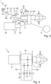
- the internal combustion engine system 5 has an internal combustion engine 22 for driving the hydraulic pump drive shaft 4 of the hydraulic drive pump system 3, as shown in FIG 3 shown.
- the internal combustion engine system 5 has a vehicle transmission 23 .
- the liquid-cooled synchronous drive motor 6 has a synchronous motor 24 for driving the hydraulic pump drive shaft 4 of the hydraulic drive pump system 3, as shown in FIG 2 shown.
- the liquid-cooled synchronous drive motor 6 has a liquid cooling system 25 for cooling the synchronous motor 24, as in FIG 3 shown.
- the truck-mounted concrete pump 2 has a concrete placing boom 16, as shown in 1 shown.
- the concrete placing boom 16 is designed for distributing delivered concrete.
- the hydraulic drive pump system 3 is designed to drive the concrete placing boom 16 .
- the truck-mounted concrete pump has a structure 7 and a vehicle frame 8, as in 2 shown.
- the structure 7 carries the concrete pump system 2.
- the vehicle frame 8 carries the structure 7.
- the liquid-cooled synchronous drive motor 6, in particular the synchronous motor 24, is spatially arranged between the main longitudinal beams 17 of the vehicle frame 8.
- the liquid-cooled synchronous drive motor may additionally or alternatively be spatially arranged between main side rails of the body.
- the structure 7 also carries the concrete placing boom 16. Furthermore, in the exemplary embodiment shown, the hydraulic pump drive shaft 4 of the hydraulic drive pump system 3 is spatially arranged between the main longitudinal beams 17 of the vehicle frame 8.
- the truck-mounted concrete pump 1 has at least one travel drive axle 9 .
- the internal combustion engine system 5, in particular the internal combustion engine 22, is designed to drive the at least one travel drive axle 9, as in 3 shown.
- the truck-mounted concrete pump 1 has two travel drive axles 9 .
- the truck-mounted concrete pump can only have one Have traction drive axle or at least three traction drive axles.
- the at least one travel drive axle 9 is a rear axle.
- the truck-mounted concrete pump 1 has a transfer case 10 .
- the transfer case 10 is designed to connect the internal combustion engine system 5 either to the at least one travel drive axle 9 or to the hydraulic pump drive shaft 4 of the hydraulic drive pump system 3, as shown in FIG 4 shown.
- the transfer case 10 is spatially arranged between the main longitudinal members 17 of the vehicle frame 8 .
- the internal combustion engine system 5, in particular the vehicle transmission 23, is mechanically connected to the transfer case 10, in particular by means of a cardan shaft 11.
- the hydraulic drive pump system 3 has a number of hydraulic drive pumps 12 .
- the transfer case 10 has an input side IS and an opposite output side OS.
- the internal combustion engine system 5, in particular the internal combustion engine 22 and the vehicle transmission 23, and the liquid-cooled synchronous drive motor 6, in particular the synchronous motor 24, are spatially arranged on the drive side IS.
- the number of hydraulic drive pumps 12 is spatially arranged on the output side OS, in particular directly flanged to the transfer case 10 .
- the hydraulic drive pump system 3 has four hydraulic drive pumps 12 .
- the hydraulic drive pump system may include only a single hydraulic drive pump, or two, three, or at least five hydraulic drive pumps.
- the at least one travel drive axle 9 is spatially arranged on the output side OS.
- the number of hydraulic drive pumps 12 is spatially arranged between the main side members 17 of the vehicle frame 8 .
- at least one of the number of hydraulic drive pumps may be spatially located on the drive side.
- the liquid-cooled synchronous drive motor in particular the synchronous motor, in particular with a through drive, can be arranged between the hydraulic drive pump arranged on the drive side and the transfer case.
- the number of hydraulic drive pumps 12 is designed to drive the concrete pump system 2, in particular the at least one drive piston.
- the hydraulic pump drive shaft 4 is designed to drive the number of hydraulic drive pumps 12 .
- the number of hydraulic drive pumps 12 is mechanically rigidly connected to the hydraulic pump drive shaft 4, in particular the number of hydraulic drive pumps 12 is seated on the hydraulic pump drive shaft 4.
- liquid-cooled synchronous drive motor 6, in particular the synchronous motor 24, is connected to the hydraulic pump drive shaft 4 of the hydraulic drive pump system 3 through the transfer case 10, in particular flanged directly to the transfer case 10.
- liquid-cooled synchronous drive motor 6, in particular the synchronous motor 24, is mechanically rigidly connected to the hydraulic pump drive shaft 4 of the hydraulic drive pump system 3, in particular the liquid-cooled synchronous drive motor 6, in particular the synchronous motor 24, is seated on the hydraulic pump drive shaft 4.
- the hydraulic pump drive shaft 4 of the hydraulic drive pump system 3 extends through the transfer case 10, in particular from the output side OS to the input side IS.
- liquid-cooled synchronous drive motor 6, in particular the synchronous motor 24, is designed to run idle.
- the liquid-cooled synchronous drive motor in particular the synchronous motor
- the liquid-cooled synchronous drive motor can be connected to the hydraulic pump drive shaft of the hydraulic drive pump system and/or to the internal combustion drive engine system via a separable clutch or a freewheel, in particular between the liquid-cooled synchronous drive motor, in particular the synchronous motor, and the transfer case the liquid-cooled synchronous drive motor, in particular the synchronous motor, cannot be designed to run idle.
- the liquid-cooled synchronous drive motor in particular the synchronous motor, can have, in particular be, a hollow shaft motor.
- the hollow shaft motor can sit on the cardan shaft and be designed to drive the cardan shaft.
- the liquid-cooled synchronous drive motor, in particular the Synchronous motor, in particular the hollow shaft motor be integrated into the vehicle transmission, if available.
- the engine system 5 can drive the hydraulic pump drive shaft 4 of the hydraulic drive pump system 3 .
- a shaft of the liquid-cooled synchronous drive motor 6, in particular the synchronous motor 24, can run idle.
- the liquid-cooled synchronous drive motor 6, in particular the synchronous motor 24, can also drive the hydraulic pump drive shaft 4 of the hydraulic drive pump system 3.
- the at least one travel drive axle 9 is decoupled.
- the internal combustion engine system 5 can drive the at least one travel drive axle 9 .
- the liquid-cooled synchronous drive motor 6, in particular the synchronous motor 24, can drive the hydraulic pump drive shaft 4 of the hydraulic drive pump system 3.
- the displacement shaft 26 and an in 4 upper shaft, in particular the hydraulic pump drive shaft 4, are decoupled.
- liquid-cooled synchronous drive motor 6, in particular the synchronous motor 24, is designed for a rated electrical power P6 of at least 60 kW, in particular at least 80 kW.
- the liquid-cooled synchronous drive motor 6, in particular the synchronous motor 24, has an electrical rated power density PD6 of at least 0.4 kW/kg, in particular at least 0.5 kW/kg.
- the truck-mounted concrete pump 1 has an electricity network connection 13 .
- the electricity mains connection 13 is electrically connected, in particular by a converter 19, to the liquid-cooled synchronous drive motor 6, in particular to the synchronous motor 24.
- the electricity grid connection 13 is designed for electrical connection to an electrical building site grid connection 14, in particular a three-phase grid.
- the electricity mains connection 13 has a mains plug 20 and a power cable 21 .
- the electricity grid connection 13 or the electrical construction site grid connection 14 feeds the liquid-cooled synchronous drive motor 6, in particular the synchronous motor 24, the converter 19 converts AC voltage to DC voltage to AC voltage.
- the truck-mounted concrete pump 1 has an electrical energy store 15 .
- the electrical energy store 15 is electrically connected, in particular by the converter 19, to the liquid-cooled synchronous drive motor 6, in particular to the synchronous motor 24.
- the electrical energy store 15 is designed to deliver electrical power P15 to the liquid-cooled synchronous drive motor 6 , in particular the synchronous motor 24 .
- the electrical energy store 15 feeds the liquid-cooled synchronous drive motor 6, in particular the synchronous motor 24, the converter 19 converts DC voltage to AC voltage.
- the electrical energy store 15 is electrically connected and designed to receive electrical power Pex that is not required by the liquid-cooled synchronous drive motor 6 , in particular the synchronous motor 24 , from the electricity network connection 13 , in particular through the converter 19 .
- the electrical energy store 15 is designed to deliver the electrical power P15 required by the liquid-cooled synchronous drive motor 6 , in particular the synchronous motor 24 , in addition to the electrical power Pin from the electricity network connection 13 .
- the electricity network connection 13 or the electrical construction site network connection 14 feeds or charges the electrical energy store 15, the converter 19 converts alternating voltage AC to direct voltage DC.
- the truck-mounted concrete pump 1 has the electricity network connection 13 and the electrical energy store 15 .
- the truck-mounted concrete pump may only have the electricity grid connection.
- the truck-mounted concrete pump cannot or does not have to have the electrical energy store.
- the truck-mounted concrete pump can be described as an accumulator-less parallel hybrid truck-mounted concrete pump.
- the invention provides an advantageous truck-mounted concrete pump which has improved properties.
- the truck-mounted concrete pump enables effective work with relatively low or even zero exhaust emissions and a relatively low noise level for the first time.
Landscapes
- Engineering & Computer Science (AREA)
- Mechanical Engineering (AREA)
- Architecture (AREA)
- General Engineering & Computer Science (AREA)
- Civil Engineering (AREA)
- Structural Engineering (AREA)
- Chemical & Material Sciences (AREA)
- Combustion & Propulsion (AREA)
- Health & Medical Sciences (AREA)
- Public Health (AREA)
- Transportation (AREA)
- Details Of Reciprocating Pumps (AREA)
- Auxiliary Drives, Propulsion Controls, And Safety Devices (AREA)
- Reciprocating Pumps (AREA)
- On-Site Construction Work That Accompanies The Preparation And Application Of Concrete (AREA)
- Electric Propulsion And Braking For Vehicles (AREA)
Description
- Die Erfindung bezieht sich auf eine Autobetonpumpe.
- Die
EP 3 023 212 A1 von CIFA S.P.A. bzw. ein Youtube-Video von CIFA mit Titel "CIFA Hybrid Technology" offenbart ein Fahrzeug zum Ausbringen von Beton, bestehend aus einem Bewegungsmittel, beispielsweise einem Lastwagen, versehen mit einem Hauptmotor zum Bewegen des Lastwagens unter Verwendung einer Bewegungseinheit, einer Einheit zum Ausbringen von Beton ausgestattet mit einer Pumpvorrichtung, die so konfiguriert ist, dass sie den Beton entlang einer Leitung fördert. Das Fahrzeug umfasst eine Einheit zum Erzeugen und Einspeisen von elektrischer Energie, die so konfiguriert ist, um wahlweise eine oder mehrere von entweder der Bewegungseinheit das Lastwagens, der Betonausbringeinheit und der Pumpvorrichtung zu speisen. - Des Weiteren offenbart die
DE 10 2010 046 615 A1 eine Vorrichtung zur Klimatisierung eines Kraftfahrzeugs. Das Kraftfahrzeug weist mindestens eine elektrische Maschine auf. Die Vorrichtung umfasst mindestens einen Fluidkreislauf. Im Fluidkreislauf sind mindestens ein Wärmetauscher, eine Pumpe und ein Thermospeicher angeordnet. Die elektrische Maschine bildet den Thermospeicher aus. Der Begriff "elektrische Maschine" umfasst hierbei alle bekannten Maschinen, mittels derer aus elektrischer Energie mechanische Energie erzeugbar ist, beispielsweise Asynchronmaschinen, Synchronmaschinen und Gleichstrommaschinen. - Außerdem offenbart die
EP 1 713 159 A1 einen Variable-Drehzahl-synchron-elektrischen-Motor mit einem Rotor getaucht in eine Flüssigkeit besonders für Pumpen. - Weiter offenbart die
CN 202 969 950 U eine Betonpumpvorrichtung mit Hybridantrieb. - Zudem offenbart die
US 6 022 048 A ein Antriebsmotor-Montagemodul für ein Hybrid-Elektrofahrzeug und das Motor-Montagemodul in Kombination mit dem Hybrid-Elektrofahrzeug. Mehr spezifisch besteht das Antriebsmotor-Montagemodul aus einem Antriebsmotor, einer vorderen Motorhalterungshalterung, einer vorderen Chassishalterung, einem Chassisquerträger, zwei hinteren Motorhalterungen, zwei Querstreben, zwei vertikalen Kanälen und zwei Motormodule Lokalisierungs-Halterungen. Das gesamte Modul kann vor dem Einbau in das Fahrzeugchassis auf einer Hauptmontagelinie modular zusammengebaut werden. Das Montagemodul bringt den Antriebsmotor durch Dreipunkthalterungen mit dem Fahrchassis in Eingriff. - Der Erfindung liegt als Aufgabe die Bereitstellung einer Autobetonpumpe zugrunde, die verbesserte Eigenschaften aufweist.
- Die Erfindung löst diese Aufgabe durch die Bereitstellung einer Autobetonpumpe mit den Merkmalen des Anspruchs 1. Vorteilhafte Weiterbildungen und/oder Ausgestaltungen der Erfindung sind in den abhängigen Ansprüchen beschrieben.
- Die erfindungsgemäße Autobetonpumpe weist ein Betonpumpsystem, ein Hydraulikantriebspumpsystem, ein Verbrennungsantriebsmotorsystem und einen flüssigkeitsgekühlten, insbesondere wasser- oder ölgekühlten, Synchronantriebsmotor auf. Das Betonpumpsystem ist zur, insbesondere automatischen, Förderung beziehungsweise zum, insbesondere automatischen, Pumpen von Beton ausgebildet. Das Hydraulikantriebspumpsystem ist zum, insbesondere automatischen und/oder hydraulischen, Antrieb des Betonpumpsystems ausgebildet. Des Weiteren weist das Hydraulikantriebspumpsystem eine Hydraulikpumpenantriebswelle auf. Das Verbrennungsantriebsmotorsystem ist zum, insbesondere automatischen und/oder mechanischen, Antrieb der Hydraulikpumpenantriebswelle des Hydraulikantriebspumpsystems ausgebildet. Der flüssigkeitsgekühlte Synchronantriebsmotor ist zum, insbesondere automatischen und/oder mechanischen, Antrieb der, insbesondere derselben, Hydraulikpumpenantriebswelle des Hydraulikantriebspumpsystems ausgebildet.
- Der flüssigkeitsgekühlte Synchronantriebsmotor kann ein relativ kleines Volumen und/oder eine relativ geringe Masse beziehungsweise ein relativ geringes Gewicht aufweisen. Somit kann der flüssigkeitsgekühlte Synchronantriebsmotor ermöglichen, dass der flüssigkeitsgekühlte Synchronantriebsmotor und das Verbrennungsantriebsmotorsystem die, insbesondere dieselbe, Hydraulikpumpenantriebswelle des Hydraulikantriebspumpsystems antreiben können. Insbesondere kann die Autobetonpumpe nur ein einziges Hydraulikantriebspumpsystem aufweisen, insbesondere aufweisend nur eine einzige Hydraulikpumpenantriebswelle. In anderen Worten: die Autobetonpumpe kann oder braucht nicht eine Mehrzahl von Hydraulikantriebspumpsystemen aufweisend eine Mehrzahl von Hydraulikpumpenantriebswellen aufweisen. Somit kann der flüssigkeitsgekühlte Synchronantriebsmotor eine relativ kompakte und/oder relativ leichte Bauweise der Autobetonpumpe, insbesondere mit relativ wenigen Komponenten, ermöglichen. Somit kann die Autobetonpumpe erstmalig ein effektives Arbeiten, insbesondere eine effektive Förderung von Beton, mit relativ geringer oder sogar mit Null Abgas-Emission und/oder mit relativ geringerem Geräuschpegel beziehungsweise Lautstärkepegel ermöglichen. Insbesondere kann somit die Autobetonpumpe auf einer innerstädtischen Baustelle eingesetzt werden.
- Insbesondere kann die Autobetonpumpe als fahrbare, insbesondere selbstfahrende, Betonpumpe bezeichnet werden.
- Zusätzlich oder alternativ kann das Betonpumpensystem mindestens eine Kolbenpumpe, insbesondere eine Doppelkolbenpumpe, zur, insbesondere automatischen, Förderung von Beton aufweisen.
- Weiter zusätzlich weist das Hydraulikantriebspumpsystem eine Anzahl von Hydraulikantriebspumpen zum, insbesondere automatischen und/oder hydraulischen, Antrieb des Betonpumpsystems auf.
- Die Hydraulikpumpenantriebswelle kann zum, insbesondere automatischen und/oder mechanischen, Antrieb der Anzahl von Hydraulikantriebspumpen ausgebildet sein. Insbesondere kann die Anzahl von Hydraulikantriebspumpen mit der Hydraulikpumpenantriebswelle mechanisch starr verbunden sein, insbesondere auf der Hydraulikpumpenantriebswelle sitzen. Zusätzlich oder alternativ kann das Hydraulikantriebspumpsystem von dem Betonpumpsystem verschieden sein.
- Weiter zusätzlich oder alternativ kann das Verbrennungsantriebsmotorsystem einen, insbesondere nur einen einzigen, Verbrennungsantriebsmotor, insbesondere einen Dieselmotor, zum, insbesondere automatischen und/oder mechanischen, Antrieb der Hydraulikpumpenantriebswelle des Hydraulikantriebspumpsystems aufweisen. Zusätzlich kann das Verbrennungsantriebsmotorsystem ein Fahrzeuggetriebe aufweisen. Weiter zusätzlich oder alternativ kann das Verbrennungsantriebsmotorsystem von dem Hydraulikantriebspumpsystem verschieden sein.
- Weiter zusätzlich oder alternativ kann der flüssigkeitsgekühlte Synchronantriebsmotor einen, insbesondere nur einen einzigen, Synchronmotor zum, insbesondere automatischen und/oder mechanischen, Antrieb der Hydraulikpumpenantriebswelle des Hydraulikantriebspumpsystems aufweisen. Insbesondere kann der Synchronmotor mit Reluktanzeffekt sein. Zusätzlich oder alternativ kann der Synchronmotor eine Einphasen- oder Drehstrom-Synchronmaschine im Motorbetrieb sein, bei der ein konstant magnetisierter Läufer (Rotor) synchron von einem bewegten magnetischen Drehfeld im Stator mitgenommen werden kann. Zusätzlich kann der flüssigkeitsgekühlte Synchronantriebsmotor eine Flüssigkeitskühlung, insbesondere eine Wasser- oder Ölkühlung, zu der beziehungsweise für die Kühlung des Synchronmotors aufweisen. Die Flüssigkeitskühlung kann ein Kühlsystem, insbesondere ein Kühlkreislaufsystem, bezeichnen, bei dem das primär wärmeabführende Kühlmittel eine Flüssigkeit, insbesondere Wasser oder Öl, sein kann. Weiter zusätzlich oder alternativ kann der flüssigkeitsgekühlte Synchronantriebsmotor von dem Verbrennungsantriebsmotorsystem und/oder von dem Hydraulikantriebspumpsystem verschieden sein.
- Weiter zusätzlich oder alternativ kann die Autobetonpumpe dazu ausgebildet sein, dass, insbesondere zu einem Zeitpunkt, entweder, insbesondere ausschließlich, das Verbrennungsantriebsmotorsystem oder, insbesondere ausschließlich, der flüssigkeitsgekühlte Synchronantriebsmotor oder, insbesondere gleichzeitig, das Verbrennungsantriebsmotorsystem und der flüssigkeitsgekühlte Synchronantriebsmotor die Hydraulikpumpenantriebswelle des Hydraulikantriebspumpsystems antreiben kann/können. Zusätzlich kann die Autobetonpumpe zum, insbesondere automatischen, Umschalten beziehungsweise Umstellen zwischen dem Verbrennungsantrieb und/oder dem Synchronantrieb beziehungsweise Elektrobetrieb und/oder dem Hybridbetrieb ausgebildet sein. Weiter zusätzlich oder alternativ kann die Autobetonpumpe als Parallel-Hybrid-Autobetonpumpe bezeichnet werden.
- Die Autobetonpumpe weist einen Aufbau und einen, insbesondere von dem Aufbau verschiedenen, Fahrzeugrahmen auf. Der Aufbau trägt das Betonpumpsystem. Der Fahrzeugrahmen trägt den Aufbau. Der flüssigkeitsgekühlte Synchronantriebsmotor ist teilweise zwischen Hauptlängsträgern des Aufbaus und/oder des Fahrzeugrahmens räumlich angeordnet. Dies ermöglicht eine optimale Nutzung des Bauraums. Anders formuliert: der flüssigkeitsgekühlte Synchronantriebsmotor kann oder braucht nicht auf dem Aufbau räumlich angeordnet sein beziehungsweise der Aufbau kann oder braucht nicht den flüssigkeitsgekühlten Synchronantriebsmotor tragen. Somit kann oder braucht der flüssigkeitsgekühlte Synchronantriebsmotor keinen Bauraum beziehungsweise keine Fläche auf dem Aufbau beanspruchen. Insbesondere kann der Aufbau als Pritsche, insbesondere im rechten oder linken Bereich der Autobetonpumpe, bezeichnet werden. Zusätzlich oder alternativ kann der Fahrzeugrahmen als Fahrzeugchassis bezeichnet werden. Weiter zusätzlich oder alternativ kann der Fahrzeugrahmen ein Lastkraftwagenrahmen sein beziehungsweise die Autobetonpumpe kann auf einem Lastkraftwagen aufgebaut sein. Weiter zusätzlich oder alternativ kann der flüssigkeitsgekühlte Synchronantriebsmotor vollständig zwischen Hauptlängsträgern des Aufbaus und/oder des Fahrzeugrahmens räumlich angeordnet sein oder in vertikaler Richtung nach unten und/oder nach oben über die Hauptlängsträger sich hinauserstrecken.
- Die Autobetonpumpe weist mindestens eine Fahrantriebsachse auf. Das Verbrennungsantriebsmotorsystem ist zum, insbesondere automatischen und/oder mechanischen, Antrieb der mindestens einen Fahrantriebsachse ausgebildet. Somit kann das Verbrennungsantriebsmotorsystem sowohl Fahrbetrieb als auch Pumpbetrieb der Autobetonpumpe gewährleisten. Insbesondere kann die Autobetonpumpe dazu ausgebildet sein, dass, insbesondere zu einem Zeitpunkt, das Verbrennungsantriebsmotorsystem entweder, insbesondere ausschließlich, die mindestens eine Fahrantriebsachse oder, insbesondere ausschließlich, die Hydraulikpumpenantriebswelle des Hydraulikantriebspumpsystems antreiben kann. Zusätzlich kann die Autobetonpumpe zum, insbesondere automatischen, Umschalten beziehungsweise Umstellen zwischen dem Fahrbetrieb und dem Pumpbetrieb ausgebildet sein.
- Die Autobetonpumpe weist ein Verteilergetriebe auf. Das Verteilergetriebe ist dazu ausgebildet, insbesondere zu einem Zeitpunkt, das Verbrennungsantriebsmotorsystem entweder mit, insbesondere ausschließlich, der mindestens einen Fahrantriebsachse oder mit, insbesondere ausschließlich, der Hydraulikpumpenantriebswelle des Hydraulikantriebspumpsystems, insbesondere automatisch und/oder mechanisch, zu verbinden.
- Das Hydraulikantriebspumpsystem weist eine, insbesondere die, Anzahl von Hydraulikantriebspumpen auf. Das Verteilergetriebe weist eine Antriebsseite und eine gegenüberliegende beziehungsweise abgewandte Abtriebsseite auf. Das Verbrennungsantriebsmotorsystem und der flüssigkeitsgekühlte Synchronantriebsmotor sind, insbesondere vollständig, auf der Antriebsseite räumlich angeordnet. Des Weiteren ist die Anzahl von Hydraulikantriebspumpen, insbesondere vollständig, auf der Abtriebsseite räumlich angeordnet. Dies ermöglicht eine optimale Nutzung des Bauraums. Insbesondere kann oder braucht keine Hydraulikantriebspumpe auf der Antriebsseite räumlich angeordnet sein. Zusätzlich oder alternativ kann die Fahrantriebsachse auf der Abtriebsseite räumlich angeordnet sein.
- In einer Ausgestaltung der Erfindung ist das Verbrennungsantriebsmotorsystem mit dem Verteilergetriebe mechanisch verbunden, insbesondere mittels einer Kardanwelle, insbesondere ausschließlich mittels der Kardanwelle. Dies ermöglicht eine relativ einfache Verbindung, insbesondere mit relativ wenigen Komponenten. Insbesondere kann oder braucht das Verbrennungsantriebsmotorsystem mit dem Verteilergetriebe nicht hydraulisch verbunden sein.
- In einer Ausgestaltung der Erfindung ist der flüssigkeitsgekühlte Synchronantriebsmotor mit der Hydraulikpumpenantriebswelle des Hydraulikantriebspumpsystems durch beziehungsweise über das Verteilergetriebe, insbesondere hindurch und/oder mechanisch, verbunden, insbesondere an das Verteilergetriebe direkt beziehungsweise unmittelbar angeflanscht. Dies ermöglicht das Verteilgetriebe zum Verteilen der mechanischen Energie zweier Antriebe, nämlich des Verbrennungsantriebsmotorsystems und des flüssigkeitsgekühlten Synchronantriebsmotors, zu nutzen. Insbesondere kann die Autobetonpumpe zum, insbesondere automatischen, Umschalten beziehungsweise Umstellen zwischen dem Verbrennungsantrieb und/oder dem Synchronantrieb und/oder dem Hybridbetrieb durch beziehungsweise über das Verteilergetriebe ausgebildet sein. Zusätzlich oder alternativ kann die Hydraulikpumpenantriebswelle des Hydraulikantriebspumpsystems sich durch das Verteilergetriebe hindurch, insbesondere von der Abtriebsseite zu der Antriebsseite, erstrecken. Weiter zusätzlich oder alternativ kann der flüssigkeitsgekühlte Synchronantriebsmotor auf der gleichen Seite wie das Verbrennungsantriebsmotorsystem und/oder auf der Antriebsseite an das Verteilergetriebe angeflanscht sein.
- In einer Weiterbildung der Erfindung ist der flüssigkeitsgekühlte Synchronantriebsmotor mit der Hydraulikpumpenantriebswelle des Hydraulikantriebspumpsystems mechanisch starr verbunden, insbesondere sitzt der flüssigkeitsgekühlte Synchronantriebsmotor auf der Hydraulikpumpenantriebswelle. Dies ermöglicht eine relativ einfache Verbindung, insbesondere mit relativ wenigen Komponenten. Insbesondere kann der flüssigkeitsgekühlte Synchronantriebsmotor ohne oder braucht nicht durch beziehungsweise über eine trennbare Kupplung oder einen Freilauf mit der Hydraulikpumpenantriebswelle des Hydraulikantriebspumpsystems und/oder mit dem Verbrennungsantriebsmotorsystem verbunden sein. Zusätzlich oder alternativ kann der flüssigkeitsgekühlte Synchronantriebsmotor zum leeren Mitlaufen beziehungsweise passiven Mitdrehen, insbesondere im Verbrennungsantrieb, ausgebildet sein.
- In einer Weiterbildung der Erfindung ist der flüssigkeitsgekühlte Synchronantriebsmotor für eine elektrische Nennleistung von mindestens 60 Kilowatt (kW), insbesondere von mindestens 80 kW, ausgebildet. Zusätzlich oder alternativ weist der flüssigkeitsgekühlte Synchronantriebsmotor eine elektrische Nennleistungsdichte von mindestens 0,4 Kilowatt pro Kilogramm (kW/kg), insbesondere von mindestens 0,5 kW/kg, auf. Dies kann ermöglichen, dass der flüssigkeitsgekühlte Synchronantriebsmotor die volle Funktionalität der Autobetonpumpe, insbesondere des Hydraulikantriebspumpsystems und somit des Betonpumpsystems, abdecken und sowohl für Vollast- als auch Teillastbetrieb ausgelegt sein kann. Insbesondere kann die elektrische Nennleistung eine Dauerleistung bezeichnen, wobei die Dauerleistung des flüssigkeitsgekühlten Synchronantriebsmotors die höchste Leistung sein kann, die bei einem bestimmungsgemäßen Betrieb ohne zeitliche Einschränkung erbracht werden und eine Lebensdauer und Sicherheit des flüssigkeitsgekühlte Synchronantriebsmotors nicht beeinträchtigen kann. Zusätzlich oder alternativ kann die elektrische Nennleistung durch beziehungsweise über P6 = √3 × I × U für Drehstrom (I: Strom, U: Spannung) definiert sein.
- In einer Weiterbildung der Erfindung weist die Autobetonpumpe einen Elektrizitätsnetzanschluss auf. Der Elektrizitätsnetzanschluss ist, insbesondere durch beziehungsweise über einen, insbesondere elektrischen, Konverter beziehungsweise Umsetzer, mit dem flüssigkeitsgekühlten Synchronantriebsmotor elektrisch verbunden. Des Weiteren ist der Elektrizitätsnetzanschluss zum elektrischen Anschluss an einen elektrischen Baustellennetzanschluss, insbesondere eines Baustromverteilerkastens und/oder eines Drehstromnetzes, ausgebildet. Dies ermöglicht den relativ hohen Leistungsbedarf der Autobetonpumpe, insbesondere des flüssigkeitsgekühlten Synchronantriebsmotors, durch beziehungsweise über den Baustellenstrom abzudecken. Wird mehr Leistung benötigt, kann das Verbrennungsantriebsmotorsystem zugeschaltet werden. Insbesondere kann der Elektrizitätsnetzanschluss zur Abgabe elektrischer Leistung beziehungsweise elektrischer Energie an den flüssigkeitsgekühlten Synchronantriebsmotor ausgebildet sein. Zusätzlich oder alternativ kann der Elektrizitätsnetzanschluss einen Netzstecker, insbesondere einen Drehstromsteckverbinder, aufweisen. Weiter zusätzlich oder alternativ kann die Autobetonpumpe, insbesondere können die elektrischen Komponenten, derart ausgebildet beziehungsweise konzipiert sein, dass der Pumpenfahrer selbst den elektrischen Anschluss herstellen kann, insbesondere den Netzstecker in eine korrespondierende Buchse beziehungsweise Dose des Baustellennetzanschlusses einstecken kann. Dies kann ermöglichen, dass nicht extra ein Elektriker zum elektrischen Anschluss der Autobetonpumpe bestellt werden braucht oder muss.
- In einer Weiterbildung der Erfindung weist die Autobetonpumpe einen elektrischen Energiespeicher, insbesondere einen Akkumulator, auf. Der elektrische Energiespeicher ist, insbesondere durch beziehungsweise über einen, insbesondere den und/oder elektrischen, Konverter beziehungsweise Umsetzer, mit dem flüssigkeitsgekühlten Synchronantriebsmotor elektrisch verbunden. Des Weiteren ist der elektrische Energiespeicher zur Abgabe elektrischer Leistung beziehungsweise elektrischer Energie an den flüssigkeitsgekühlten Synchronantriebsmotor ausgebildet. Dies ermöglicht die Autobetonpumpe bei NichtVorhandensein eines elektrischen Baustellennetzanschlusses mindestens teilweise elektrisch zu betreiben. Wird mehr Leistung benötigt, kann das Verbrennungsantriebsmotorsystem zugeschaltet werden. Insbesondere kann die Autobetonpumpe dazu ausgebildet sein, den elektrischen Energiespeicher durch beziehungsweise über den flüssigkeitsgekühlten Synchronantriebsmotor als Generator von dem Verbrennungsantriebsmotorsystem aufzuladen, insbesondere falls das Verbrennungsantriebsmotorsystem mehr Leistung beziehungsweise Energie liefern kann, als von dem Hydraulikantriebspumpsystem, insbesondere temporär, benötigt.
- In einer Ausgestaltung der Erfindung ist der elektrische Energiespeicher zur Aufnahme von dem flüssigkeitsgekühlten Synchronantriebsmotor, insbesondere temporär beziehungsweise zu einem ersten Zeitpunkt, nicht benötigter beziehungsweise überschüssiger elektrischer Leistung von beziehungsweise mit dem Elektrizitätsnetzanschluss, insbesondere durch beziehungsweise über einen, insbesondere den und/oder elektrischen, Konverter beziehungsweise Umsetzer, elektrisch verbunden und ausgebildet. Des Weiteren ist der elektrische Energiespeicher zur Abgabe von dem flüssigkeitsgekühlten Synchronantriebsmotor, insbesondere temporär beziehungsweise zu einem von dem ersten verschiedenen, zweiten Zeitpunkt, benötigter elektrischer Leistung beziehungsweise elektrischer Energie zusätzlich zur elektrischen Leistung von dem Elektrizitätsnetzanschluss ausgebildet. Typischerweise stellt der elektrische Baustellennetzanschluss nur eine begrenzte elektrische Leistung bereit beziehungsweise ist auf eine bestimmte elektrische Leistungsbelastung begrenzt. Die Autobetonpumpe, insbesondere der elektrische Energiespeicher, ermöglicht, dass dem flüssigkeitsgekühlten Synchronantriebsmotor mindestens temporär beziehungsweise zeitweise mehr elektrische Leistung zur Verfügung steht als von dem elektrischen Baustellennetzanschluss bereitgestellt. Insbesondere können einen, insbesondere kurzzeitigen, relativ hohen Leistungsbedarf beziehungsweise eine Leistungsspitze des flüssigkeitsgekühlten Synchronantriebsmotors der Elektrizitätsnetzanschluss beziehungsweise der elektrische Baustellennetzanschluss und zusätzlich der elektrische Energiespeicher decken, insbesondere gleichzeitig. Zu Zeitpunkten mit relativ geringem Leistungsbedarf kann der elektrische Energiespeicher die nicht benötigte elektrische Leistung des Elektrizitätsnetzanschlusses aufnehmen. In anderen Worten: bei Überlast kann der elektrische Energiespeicher angezapft werden, bei Leistungsreserve kann der elektrische Energiespeicher aufgeladen werden.
- In einer Weiterbildung der Erfindung weist die Autobetonpumpe einen Betonverteilermast auf. Der Betonverteilermast ist zur Verteilung von, insbesondere von dem Betonpumpsystem, gefördertem beziehungsweise gepumptem Beton ausgebildet. Das Hydraulikantriebspumpsystem ist zum Antrieb des Betonverteilermasts ausgebildet.
- Weitere Vorteile und Aspekte der Erfindung ergeben sich aus den Ansprüchen und aus der nachfolgenden Beschreibung von bevorzugten Ausführungsbeispielen der Erfindung, die nachfolgend anhand der Figuren erläutert sind. Dabei zeigen:
- Fig. 1
- eine Seitenansicht einer erfindungsgemäßen Autobetonpumpe,
- Fig. 2
- eine Draufsicht auf einen Aufbau und einen Fahrzeugrahmen in einem in
Fig. 1 gestrichelt markierten Einbaubereich der Autobetonpumpe derFig. 1 , - Fig. 3
- einen Schaltplan der Autobetonpumpe der
Fig. 1 , und - Fig. 4
- einen weiteren Schaltplan der Autobetonpumpe der
Fig. 1 . -
Fig. 1 bis 4 zeigen eine erfindungsgemäße Autobetonpumpe 1. Die Autobetonpumpe 1 weist ein Betonpumpsystem 2, ein Hydraulikantriebspumpsystem 3, ein Verbrennungsantriebsmotorsystem 5 und einen flüssigkeitsgekühlten Synchronantriebsmotor 6 auf. Das Betonpumpsystem 2 ist zur Förderung von Beton ausgebildet. Das Hydraulikantriebspumpsystem 3 ist zum Antrieb des Betonpumpsystems 2 ausgebildet. Des Weiteren weist das Hydraulikantriebspumpsystem 3 eine Hydraulikpumpenantriebswelle 4 auf. Das Verbrennungsantriebsmotorsystem 5 ist zum Antrieb der Hydraulikpumpenantriebswelle 4 des Hydraulikantriebspumpsystems 3 ausgebildet. Der flüssigkeitsgekühlte Synchronantriebsmotor 6 ist zum Antrieb der Hydraulikpumpenantriebswelle 4 des Hydraulikantriebspumpsystems 3 ausgebildet. - Im gezeigten Ausführungsbeispiel weist das Betonpumpensystem 2 mindestens eine Kolbenpumpe, insbesondere eine Doppelkolbenpumpe, zur Förderung von Beton auf. Außerdem weist im gezeigten Ausführungsbeispiel das Hydraulikantriebspumpsystem 3 mindestens einen Antriebszylinder 18, insbesondere zwei Antriebszylinder 18, und mindestens einen Antriebskolben, insbesondere zwei Antriebskolben, auf, wie in
Fig. 2 gezeigt. Der mindestens eine Antriebskolben ist zum Antrieb der mindestens einen Kolbenpumpe ausgebildet. Die Hydraulikpumpenantriebswelle 4 ist zum Antrieb des mindestens einen Antriebskolbens ausgebildet. - Weiter weist im gezeigten Ausführungsbeispiel das Verbrennungsantriebsmotorsystem 5 einen Verbrennungsantriebsmotor 22 zum Antrieb der Hydraulikpumpenantriebswelle 4 des Hydraulikantriebspumpsystems 3 auf, wie in
Fig. 3 gezeigt. Zusätzlich weist das Verbrennungsantriebsmotorsystem 5 ein Fahrzeuggetriebe 23 auf. - Zudem weist im gezeigten Ausführungsbeispiel der flüssigkeitsgekühlte Synchronantriebsmotor 6 einen Synchronmotor 24 zum Antrieb der Hydraulikpumpenantriebswelle 4 des Hydraulikantriebspumpsystems 3 auf, wie in
Fig. 2 gezeigt. Zusätzlich weist der flüssigkeitsgekühlte Synchronantriebsmotor 6 eine Flüssigkeitskühlung 25 zu der Kühlung des Synchronmotors 24 auf, wie inFig. 3 gezeigt. - Des Weiteren weist die Autobetonpumpe 2 einen Betonverteilermast 16 auf, wie in
Fig. 1 gezeigt. Der Betonverteilermast 16 ist zur Verteilung von gefördertem Beton ausgebildet. Das Hydraulikantriebspumpsystem 3 ist zum Antrieb des Betonverteilermasts 16 ausgebildet. - Außerdem weist die Autobetonpumpe einen Aufbau 7 und einen Fahrzeugrahmen 8 auf, wie in
Fig. 2 gezeigt. Der Aufbau 7 trägt das Betonpumpsystem 2. Der Fahrzeugrahmen 8 trägt den Aufbau 7. Im gezeigten Ausführungsbeispiel ist der flüssigkeitsgekühlte Synchronantriebsmotor 6, insbesondere der Synchronmotor 24, zwischen Hauptlängsträgern 17 des Fahrzeugrahmens 8 räumlich angeordnet. In alternativen Ausführungsbeispielen kann der flüssigkeitsgekühlte Synchronantriebsmotor zusätzlich oder alternativ zwischen Hauptlängsträgern des Aufbaus räumlich angeordnet sein. - Im gezeigten Ausführungsbeispiel trägt der Aufbau 7 zusätzlich den Betonverteilermast 16. Weiter ist im gezeigten Ausführungsbeispiel die Hydraulikpumpenantriebswelle 4 des Hydraulikantriebspumpsystems 3 zwischen den Hauptlängsträgern 17 des Fahrzeugrahmens 8 räumlich angeordnet.
- Zudem weist die Autobetonpumpe 1 mindestens eine Fahrantriebsachse 9 auf. Das Verbrennungsantriebsmotorsystem 5, insbesondere der Verbrennungsantriebsmotor 22, ist zum Antrieb der mindestens einen Fahrantriebsachse 9 ausgebildet, wie in
Fig. 3 gezeigt. - Im gezeigten Ausführungsbeispiel weist die Autobetonpumpe 1 zwei Fahrantriebsachsen 9 auf. In alternativen Ausführungsbeispielen kann die Autobetonpumpe nur eine einzige Fahrantriebsachse oder mindestens drei Fahrantriebsachsen aufweisen. Des Weiteren ist im gezeigten Ausführungsbeispiel die mindestens eine Fahrantriebsachse 9 eine Hinterachse.
- Außerdem weist die Autobetonpumpe 1 ein Verteilergetriebe 10 auf. Das Verteilergetriebe 10 ist dazu ausgebildet, das Verbrennungsantriebsmotorsystem 5 entweder mit der mindestens einen Fahrantriebsachse 9 oder mit der Hydraulikpumpenantriebswelle 4 des Hydraulikantriebspumpsystems 3 zu verbinden, wie in
Fig. 4 gezeigt. - Im gezeigten Ausführungsbeispiel ist das Verteilergetriebe 10 zwischen den Hauptlängsträgern 17 des Fahrzeugrahmens 8 räumlich angeordnet.
- Im Detail ist das Verbrennungsantriebsmotorsystem 5, insbesondere das Fahrzeuggetriebe 23, mit dem Verteilergetriebe 10 mechanisch verbunden, insbesondere mittels einer Kardanwelle 11.
- Weiter weist das Hydraulikantriebspumpsystem 3 eine Anzahl von Hydraulikantriebspumpen 12 auf. Das Verteilergetriebe 10 weist eine Antriebsseite IS und eine gegenüberliegende Abtriebsseite OS auf. Das Verbrennungsantriebsmotorsystem 5, insbesondere der Verbrennungsantriebsmotor 22 und das Fahrzeuggetriebe 23, und der flüssigkeitsgekühlte Synchronantriebsmotor 6, insbesondere der Synchronmotor 24, sind auf der Antriebsseite IS räumlich angeordnet. Zudem ist die Anzahl von Hydraulikantriebspumpen 12 auf der Abtriebsseite OS räumlich angeordnet, insbesondere an das Verteilergetriebe 10 direkt angeflanscht.
- Im gezeigten Ausführungsbeispiel weist das Hydraulikantriebspumpsystem 3 vier Hydraulikantriebspumpen 12 auf. In alternativen Ausführungsbeispielen kann das Hydraulikantriebspumpsystem nur eine einzige Hydraulikantriebspumpe oder zwei, drei oder mindestens fünf Hydraulikantriebspumpen aufweisen. Des Weiteren ist im gezeigten Ausführungsbeispiel die mindestens eine Fahrantriebsachse 9 auf der Abtriebsseite OS räumlich angeordnet. Außerdem ist im gezeigten Ausführungsbeispiel die Anzahl von Hydraulikantriebspumpen 12 zwischen den Hauptlängsträgern 17 des Fahrzeugrahmens 8 räumlich angeordnet. Weiter kann in alternativen Ausführungsbeispielen mindestens eine der Anzahl von Hydraulikantriebspumpen auf der Antriebsseite räumlich angeordnet sein. Insbesondere kann der flüssigkeitsgekühlte Synchronantriebsmotor, insbesondere der Synchronmotor, insbesondere mit einem Durchtrieb, zwischen der antriebsseitig angeordneten Hydraulikantriebspumpe und dem Verteilergetriebe angeordnet sein.
- Im Detail ist die Anzahl von Hydraulikantriebspumpen 12 zum Antrieb des Betonpumpsystems 2, insbesondere des mindestens einen Antriebskolbens, ausgebildet. Die Hydraulikpumpenantriebswelle 4 ist zum Antrieb der Anzahl von Hydraulikantriebspumpen 12 ausgebildet. Im gezeigten Ausführungsbeispiel ist die Anzahl von Hydraulikantriebspumpen 12 mit der Hydraulikpumpenantriebswelle 4 mechanisch starr verbunden, insbesondere sitzt die Anzahl von Hydraulikantriebspumpen 12 auf der Hydraulikpumpenantriebswelle 4.
- Zudem ist der flüssigkeitsgekühlte Synchronantriebsmotor 6, insbesondere der Synchronmotor 24, mit der Hydraulikpumpenantriebswelle 4 des Hydraulikantriebspumpsystems 3 durch das Verteilergetriebe 10 verbunden, insbesondere an das Verteilergetriebe 10 direkt angeflanscht.
- Des Weiteren ist der flüssigkeitsgekühlte Synchronantriebsmotor 6, insbesondere der Synchronmotor 24, mit der Hydraulikpumpenantriebswelle 4 des Hydraulikantriebspumpsystems 3 mechanisch starr verbunden, insbesondere sitzt der flüssigkeitsgekühlte Synchronantriebsmotor 6, insbesondere der Synchronmotor 24, auf der Hydraulikpumpenantriebswelle 4.
- Im Detail erstreckt die Hydraulikpumpenantriebswelle 4 des Hydraulikantriebspumpsystems 3 sich durch das Verteilergetriebe 10 hindurch, insbesondere von der Abtriebsseite OS zu der Antriebsseite IS.
- Außerdem ist der flüssigkeitsgekühlte Synchronantriebsmotor 6, insbesondere der Synchronmotor 24, zum leeren Mitlaufen ausgebildet.
- In alternativen Ausführungsbeispielen kann der flüssigkeitsgekühlte Synchronantriebsmotor, insbesondere der Synchronmotor, über eine trennbare Kupplung oder einen Freilauf, insbesondere zwischen dem flüssigkeitsgekühlten Synchronantriebsmotor, insbesondere dem Synchronmotor, und dem Verteilergetriebe, mit der Hydraulikpumpenantriebswelle des Hydraulikantriebspumpsystems und/oder mit dem Verbrennungsantriebsmotorsystem verbunden sein, insbesondere falls der flüssigkeitsgekühlte Synchronantriebsmotor, insbesondere der Synchronmotor, nicht zum leeren Mitlaufen ausgebildet sein kann.
- Zusätzlich oder alternativ kann in alternativen Ausführungsbeispielen der flüssigkeitsgekühlte Synchronantriebsmotor, insbesondere der Synchronmotor, einen Hohlwellenmotor aufweisen, insbesondere sein. Der Hohlwellenmotor kann auf der Kardanwelle sitzen und zum Antrieb der Kardanwelle ausgebildet sein. Weiter zusätzlich oder alternativ kann in alternativen Ausführungsbeispielen der flüssigkeitsgekühlte Synchronantriebsmotor, insbesondere der Synchronmotor, insbesondere der Hohlwellenmotor, in das Fahrzeuggetriebe, soweit vorhanden, integriert sein.
- Wenn im gezeigten Ausführungsbeispiel eine Verschiebewelle 26 des Verteilergetriebes 10 in
Fig. 4 nach links verschoben ist, kann das Verbrennungsantriebsmotorsystem 5 die Hydraulikpumpenantriebswelle 4 des Hydraulikantriebspumpsystems 3 antreiben. Eine Welle des flüssigkeitsgekühlten Synchronantriebsmotors 6, insbesondere des Synchronmotors 24, kann leer mitlaufen. Alternativ kann der flüssigkeitsgekühlte Synchronantriebsmotor 6, insbesondere der Synchronmotor 24, zusätzlich die Hydraulikpumpenantriebswelle 4 des Hydraulikantriebspumpsystems 3 antreiben. Die mindestens eine Fahrantriebsachse 9 ist entkoppelt. - Wenn im gezeigten Ausführungsbeispiel die Verschiebewelle 26 des Verteilergetriebes 10 in
Fig. 4 nach rechts verschoben ist, kann das Verbrennungsantriebsmotorsystem 5 die mindestens eine Fahrantriebsachse 9 antreiben. Der flüssigkeitsgekühlte Synchronantriebsmotor 6, insbesondere der Synchronmotor 24, kann die Hydraulikpumpenantriebswelle 4 des Hydraulikantriebspumpsystems 3 antreiben. Die Verschiebewelle 26 und eine inFig. 4 obere Welle, insbesondere die Hydraulikpumpenantriebswelle 4, sind entkoppelt. - Weiter ist der flüssigkeitsgekühlte Synchronantriebsmotor 6, insbesondere der Synchronmotor 24, für eine elektrische Nennleistung P6 von mindestens 60 kW, insbesondere von mindestens 80 kW, ausgebildet. Zusätzlich weist der flüssigkeitsgekühlte Synchronantriebsmotor 6, insbesondere der Synchronmotor 24, eine elektrische Nennleistungsdichte PD6 von mindestens 0,4 kW/kg, insbesondere von mindestens 0,5 kW/kg, auf.
- Zudem weist die Autobetonpumpe 1 einen Elektrizitätsnetzanschluss 13 auf. Der Elektrizitätsnetzanschluss 13 ist, insbesondere durch einen Konverter 19, mit dem flüssigkeitsgekühlten Synchronantriebsmotor 6, insbesondere mit dem Synchronmotor 24, elektrisch verbunden. Des Weiteren ist der Elektrizitätsnetzanschluss 13 zum elektrischen Anschluss an einen elektrischen Baustellennetzanschluss 14, insbesondere eines Drehstromnetzes, ausgebildet.
- Im Detail weist der Elektrizitätsnetzanschluss 13 einen Netzstecker 20 und ein Stromkabel 21 auf.
- Wenn im gezeigten Ausführungsbeispiel der Elektrizitätsnetzanschluss 13 beziehungsweise der elektrische Baustellennetzanschluss 14 den flüssigkeitsgekühlten Synchronantriebsmotor 6, insbesondere den Synchronmotor 24, speist, konvertiert der Konverter 19 Wechselspannung AC zu Gleichspannung DC zu Wechselspannung AC.
- Außerdem weist die Autobetonpumpe 1 einen elektrischen Energiespeicher 15 auf. Der elektrische Energiespeicher 15 ist, insbesondere durch den Konverter 19, mit dem flüssigkeitsgekühlten Synchronantriebsmotor 6, insbesondere mit dem Synchronmotor 24, elektrisch verbunden. Weiter ist der elektrische Energiespeicher 15 zur Abgabe elektrischer Leistung P15 an den flüssigkeitsgekühlten Synchronantriebsmotor 6, insbesondere den Synchronmotor 24, ausgebildet.
- Wenn im gezeigten Ausführungsbeispiel der elektrische Energiespeicher 15 den flüssigkeitsgekühlten Synchronantriebsmotor 6, insbesondere den Synchronmotor 24, speist, konvertiert der Konverter 19 Gleichspannung DC zu Wechselspannung AC.
- Im Detail ist der elektrische Energiespeicher 15 zur Aufnahme von dem flüssigkeitsgekühlten Synchronantriebsmotor 6, insbesondere dem Synchronmotor 24, nicht benötigter elektrischer Leistung Pex von dem Elektrizitätsnetzanschluss 13, insbesondere durch den Konverter 19, elektrisch verbunden und ausgebildet. Zudem ist der elektrische Energiespeicher 15 zur Abgabe von dem flüssigkeitsgekühlten Synchronantriebsmotor 6, insbesondere dem Synchronmotor 24, benötigter elektrischer Leistung P15 zusätzlich zur elektrischen Leistung Pin von dem Elektrizitätsnetzanschluss 13 ausgebildet.
- Wenn im gezeigten Ausführungsbeispiel der Elektrizitätsnetzanschluss 13 beziehungsweise der elektrische Baustellennetzanschluss 14 den elektrischen Energiespeicher 15 speist beziehungsweise auflädt, konvertiert der Konverter 19 Wechselspannung AC zu Gleichspannung DC.
- Im gezeigten Ausführungsbeispiel weist die Autobetonpumpe 1 den Elektrizitätsnetzanschluss 13 und den elektrischen Energiespeicher 15 auf. In alternativen Ausführungsbeispielen kann die Autobetonpumpe nur den Elektrizitätsnetzanschluss aufweisen. Anders formuliert: in alternativen Ausführungsbeispielen kann oder braucht die Autobetonpumpe den elektrischen Energiespeicher nicht aufweisen. Insbesondere kann die Autobetonpumpe als speicherlose Parallel-Hybrid-Autobetonpumpe bezeichnet werden.
- Wie die gezeigten und oben erläuterten Ausführungsbeispiele deutlich machen, stellt die Erfindung eine vorteilhafte Autobetonpumpe bereit, die verbesserte Eigenschaften aufweist. Insbesondere ermöglicht die Autobetonpumpe erstmalig ein effektives Arbeiten mit relativ geringer oder sogar mit Null Abgas-Emission und mit relativ geringerem Geräuschpegel.
Claims (9)
- Autobetonpumpe (1), wobei die Autobetonpumpe (1) aufweist:- ein Betonpumpsystem (2), wobei das Betonpumpsystem (2) zur Förderung von Beton ausgebildet ist,- ein Hydraulikantriebspumpsystem (3), wobei das Hydraulikantriebspumpsystem (3) zum Antrieb des Betonpumpsystems (2) ausgebildet ist und eine Hydraulikpumpenantriebswelle (4) aufweist,- ein Verbrennungsantriebsmotorsystem (5), wobei das Verbrennungsantriebsmotorsystem (5) zum Antrieb der Hydraulikpumpenantriebswelle (4) des Hydraulikantriebspumpsystems (3) ausgebildet ist,- einen flüssigkeitsgekühlten Synchronantriebsmotor (6), wobei der flüssigkeitsgekühlte Synchronantriebsmotor (6) zum Antrieb der Hydraulikpumpenantriebswelle (4) des Hydraulikantriebspumpsystems (3) ausgebildet ist,- einen Aufbau (7), wobei der Aufbau (7) das Betonpumpsystem (2) trägt,- einen Fahrzeugrahmen (8), wobei der Fahrzeugrahmen (8) den Aufbau (7) trägt,- wobei der flüssigkeitsgekühlte Synchronantriebsmotor (6) teilweise zwischen Hauptlängsträgern (17) des Aufbaus (7) und/oder des Fahrzeugrahmens (8) räumlich angeordnet ist,- mindestens eine Fahrantriebsachse (9), wobei das Verbrennungsantriebsmotorsystem (5) zum Antrieb der mindestens einen Fahrantriebsachse (9) ausgebildet ist, und- ein Verteilergetriebe (10), wobei das Verteilergetriebe (10) dazu ausgebildet ist, das Verbrennungsantriebsmotorsystem (5) entweder mit der mindestens einen Fahrantriebsachse (9) oder mit der Hydraulikpumpenantriebswelle (4) des Hydraulikantriebspumpsystems (3), insbesondere mechanisch, zu verbinden,- wobei das Hydraulikantriebspumpsystem (3) eine Anzahl von Hydraulikantriebspumpen (12) aufweist, und- wobei das Verteilergetriebe (10) eine Antriebsseite (IS) und eine gegenüberliegende Abtriebsseite (OS) aufweist, wobei das Verbrennungsantriebsmotorsystem (5) und der flüssigkeitsgekühlte Synchronantriebsmotor (6) auf der Antriebsseite (IS) räumlich angeordnet sind und die Anzahl von Hydraulikantriebspumpen (12) auf der Abtriebsseite (OS) räumlich angeordnet ist.
- Autobetonpumpe (1) nach Anspruch 1,- wobei das Verbrennungsantriebsmotorsystem (5) mit dem Verteilergetriebe (10) mechanisch verbunden ist, insbesondere mittels einer Kardanwelle (11).
- Autobetonpumpe (1) nach einem der vorhergehenden Ansprüche,- wobei der flüssigkeitsgekühlte Synchronantriebsmotor (6) mit der Hydraulikpumpenantriebswelle (4) des Hydraulikantriebspumpsystems (3) durch das Verteilergetriebe (10), insbesondere mechanisch, verbunden ist, insbesondere an das Verteilergetriebe (10) direkt angeflanscht ist.
- Autobetonpumpe (1) nach einem der vorhergehenden Ansprüche,- wobei der flüssigkeitsgekühlte Synchronantriebsmotor (6) mit der Hydraulikpumpenantriebswelle (4) des Hydraulikantriebspumpsystems (3) mechanisch starr verbunden ist, insbesondere auf der Hydraulikpumpenantriebswelle (4) sitzt.
- Autobetonpumpe (1) nach einem der vorhergehenden Ansprüche,- wobei der flüssigkeitsgekühlte Synchronantriebsmotor (6) für eine elektrische Nennleistung (P6) von mindestens 60 kW, insbesondere von mindestens 80 kW, ausgebildet ist, und/oder- wobei der flüssigkeitsgekühlte Synchronantriebsmotor (6) eine elektrische Nennleistungsdichte (PD6) von mindestens 0,4 kW/kg, insbesondere von mindestens 0,5 kW/kg, aufweist.
- Autobetonpumpe (1) nach einem der vorhergehenden Ansprüche, wobei die Autobetonpumpe (1) aufweist:- einen Elektrizitätsnetzanschluss (13), wobei der Elektrizitätsnetzanschluss (13), insbesondere durch einen Konverter (19), mit dem flüssigkeitsgekühlten Synchronantriebsmotor (6) elektrisch verbunden ist und zum elektrischen Anschluss an einen elektrischen Baustellennetzanschluss (14) ausgebildet ist.
- Autobetonpumpe (1) nach einem der vorhergehenden Ansprüche, wobei die Autobetonpumpe (1) aufweist:- einen elektrischen Energiespeicher (15), insbesondere einen Akkumulator, wobei der elektrische Energiespeicher (15), insbesondere durch einen Konverter (19), mit dem flüssigkeitsgekühlten Synchronantriebsmotor (6) elektrisch verbunden ist und zur Abgabe elektrischer Leistung (P15) an den flüssigkeitsgekühlten Synchronantriebsmotor (6) ausgebildet ist.
- Autobetonpumpe (1) nach Ansprüchen 6 und 7,- wobei der elektrische Energiespeicher (15) zur Aufnahme von dem flüssigkeitsgekühlten Synchronantriebsmotor (6) nicht benötigter elektrischer Leistung (Pex) von dem Elektrizitätsnetzanschluss (13) elektrisch verbunden und ausgebildet ist, und- wobei der elektrische Energiespeicher (15) zur Abgabe von dem flüssigkeitsgekühlten Synchronantriebsmotor (6) benötigter elektrischer Leistung (P15) zusätzlich zur elektrischen Leistung (Pin) von dem Elektrizitätsnetzanschluss (13) ausgebildet ist.
- Autobetonpumpe (1) nach einem der vorhergehenden Ansprüche, wobei die Autobetonpumpe (1) aufweist:- einen Betonverteilermast (16), wobei der Betonverteilermast (16) zur Verteilung von gefördertem Beton ausgebildet ist,- wobei das Hydraulikantriebspumpsystem (3) zum Antrieb des Betonverteilermasts (16) ausgebildet ist.
Priority Applications (2)
| Application Number | Priority Date | Filing Date | Title |
|---|---|---|---|
| EP23174445.9A EP4234846A3 (de) | 2018-09-04 | 2019-08-13 | Autobetonpumpe |
| EP23173875.8A EP4234845A3 (de) | 2018-09-04 | 2019-08-13 | Autobetonpumpe |
Applications Claiming Priority (2)
| Application Number | Priority Date | Filing Date | Title |
|---|---|---|---|
| DE102018214965.8A DE102018214965A1 (de) | 2018-09-04 | 2018-09-04 | Autobetonpumpe |
| PCT/EP2019/071675 WO2020048745A1 (de) | 2018-09-04 | 2019-08-13 | Autobetonpumpe |
Related Child Applications (2)
| Application Number | Title | Priority Date | Filing Date |
|---|---|---|---|
| EP23173875.8A Division EP4234845A3 (de) | 2018-09-04 | 2019-08-13 | Autobetonpumpe |
| EP23174445.9A Division EP4234846A3 (de) | 2018-09-04 | 2019-08-13 | Autobetonpumpe |
Publications (2)
| Publication Number | Publication Date |
|---|---|
| EP3847321A1 EP3847321A1 (de) | 2021-07-14 |
| EP3847321B1 true EP3847321B1 (de) | 2023-05-31 |
Family
ID=67660086
Family Applications (3)
| Application Number | Title | Priority Date | Filing Date |
|---|---|---|---|
| EP19755333.2A Active EP3847321B1 (de) | 2018-09-04 | 2019-08-13 | Autobetonpumpe |
| EP23174445.9A Pending EP4234846A3 (de) | 2018-09-04 | 2019-08-13 | Autobetonpumpe |
| EP23173875.8A Pending EP4234845A3 (de) | 2018-09-04 | 2019-08-13 | Autobetonpumpe |
Family Applications After (2)
| Application Number | Title | Priority Date | Filing Date |
|---|---|---|---|
| EP23174445.9A Pending EP4234846A3 (de) | 2018-09-04 | 2019-08-13 | Autobetonpumpe |
| EP23173875.8A Pending EP4234845A3 (de) | 2018-09-04 | 2019-08-13 | Autobetonpumpe |
Country Status (7)
| Country | Link |
|---|---|
| US (1) | US20210323463A1 (de) |
| EP (3) | EP3847321B1 (de) |
| JP (2) | JP7381587B2 (de) |
| KR (2) | KR102696050B1 (de) |
| CN (1) | CN112912577A (de) |
| DE (1) | DE102018214965A1 (de) |
| WO (1) | WO2020048745A1 (de) |
Families Citing this family (11)
| Publication number | Priority date | Publication date | Assignee | Title |
|---|---|---|---|---|
| DE202020101432U1 (de) | 2020-03-16 | 2021-06-17 | Liebherr-Mischtechnik Gmbh | Autobetonpumpe |
| DE102020121350A1 (de) | 2020-08-13 | 2022-02-17 | Schwing Gmbh | Autobetonpumpe |
| DE102020121360A1 (de) * | 2020-08-13 | 2022-02-17 | Schwing Gmbh | Autobetonpumpe |
| IT202100015947A1 (it) * | 2021-06-18 | 2022-12-18 | Cifa Spa | Macchina operatrice mobile e metodo di funzionamento di tale macchina operatrice mobile |
| DE102021119181B3 (de) | 2021-07-23 | 2022-08-18 | Schwing Gmbh | Zusatzaggregat und System zum elektrischen Antrieb einer Autobetonpumpe, und Autobetonpumpe |
| IT202100024436A1 (it) * | 2021-09-23 | 2023-03-23 | Cifa Spa | Macchina operatrice mobile ibrida e suo procedimento di funzionamento |
| DE102022103880A1 (de) | 2022-02-18 | 2023-08-24 | Schwing Gmbh | Zusatzaggregat und System zum elektrischen Antrieb einer Autobetonpumpe, und Autobetonpumpe |
| WO2024008566A1 (de) * | 2022-07-04 | 2024-01-11 | Schwing Gmbh | Elektrische antriebsvorrichtung für den elektrischen antrieb einer autobetonpumpe, autobetonpumpe und system zum antrieb einer autobetonpumpe |
| DE102022127899A1 (de) | 2022-07-04 | 2024-01-04 | Schwing Gmbh | Elektrische Antriebsvorrichtung für den elektrischen Antrieb einer Autobetonpumpe, Autobetonpumpe und System zum Antrieb einer Autobetonpumpe |
| DE102022210884A1 (de) * | 2022-10-14 | 2024-04-25 | Putzmeister Engineering Gmbh | Verfahren und System |
| DE102023104763A1 (de) | 2023-02-27 | 2024-08-29 | Schwing Gmbh | Betonpumpe |
Citations (11)
| Publication number | Priority date | Publication date | Assignee | Title |
|---|---|---|---|---|
| US6022048A (en) * | 1998-07-02 | 2000-02-08 | Navistar International Transportation Corp | Hybrid electric vehicle drive motor mounting module |
| JP2006136072A (ja) | 2004-11-04 | 2006-05-25 | Sumitomo (Shi) Construction Machinery Manufacturing Co Ltd | ハイブリッド式建設機械のバッテリ充電装置 |
| US20090018716A1 (en) | 2007-07-12 | 2009-01-15 | Joseph Mario Ambrosio | Parallel hybrid drive system utilizing power take off connection as transfer for a secondary energy source |
| CN201326277Y (zh) | 2008-12-05 | 2009-10-14 | 三一重工股份有限公司 | 一种混凝土泵送设备驱动装置及混凝土泵车和车载泵 |
| CN202131775U (zh) | 2011-05-27 | 2012-02-01 | 范伟林 | 混合动力混凝土泵车 |
| CN202969950U (zh) | 2012-11-20 | 2013-06-05 | 三一汽车制造有限公司 | 一种混合动力混凝土泵送设备 |
| CN104499718A (zh) | 2014-12-30 | 2015-04-08 | 株洲齿轮有限责任公司 | 一种车载泵及其动力装置 |
| CN204472590U (zh) | 2014-12-25 | 2015-07-15 | 包头市北工机械有限公司 | 一种电驱动混凝土输送泵车 |
| DE102015122591A1 (de) | 2015-12-22 | 2017-06-22 | Schwing Gmbh | Mobile Dickstoffpumpe mit Hydrauliktank |
| EP3246187A1 (de) | 2016-05-19 | 2017-11-22 | MAN Truck & Bus AG | Hybridantrieb für ein kraftfahrzeug, insbesondere für ein nutzfahrzeug |
| CN108382180A (zh) | 2018-04-19 | 2018-08-10 | 贵州大学 | 一种并联型油电混合动力车载式混凝土泵 |
Family Cites Families (19)
| Publication number | Priority date | Publication date | Assignee | Title |
|---|---|---|---|---|
| DE4041117A1 (de) * | 1990-12-21 | 1992-07-02 | Man Nutzfahrzeuge Ag | Hybridantrieb fuer fahrzeuge |
| JPH1037904A (ja) * | 1996-07-19 | 1998-02-13 | Daikin Ind Ltd | 油圧作業車 |
| DE19635200A1 (de) * | 1996-08-30 | 1998-03-05 | Putzmeister Ag | Fahrbare Dickstoffpumpe |
| JP2002315105A (ja) * | 2001-04-12 | 2002-10-25 | Komatsu Ltd | ホイールローダ |
| JP2003239852A (ja) | 2002-02-20 | 2003-08-27 | Tadano Ltd | 油圧ポンプ駆動装置 |
| DE102004028620B4 (de) * | 2004-06-12 | 2008-02-21 | Jungheinrich Ag | Antriebssystem für eine mobile Arbeitsmaschine mit angetriebenen Rädern, insbesondere ein Flurförderzeug |
| EP1713159A1 (de) * | 2005-04-11 | 2006-10-18 | Askoll Holding S.r.l. | Elektrischer Synchronmotor mit regelbarer Geschwindigkeit beinhaltend einen Nassläufer, insbesondere für Pumpen |
| DE102005035981A1 (de) * | 2005-07-28 | 2007-02-01 | Putzmeister Ag | Hydraulische Schaltungsanordnung, insbesondere für den Antrieb von Betonverteilermasten |
| NO334755B1 (no) * | 2008-12-08 | 2014-05-19 | Gjerdrum As Ing | Drivanordning for pumpe eller kompressor |
| JP5583984B2 (ja) | 2010-02-15 | 2014-09-03 | 極東開発工業株式会社 | コンクリートポンプ車両 |
| DE102010011859A1 (de) * | 2010-03-18 | 2013-01-17 | Eduard Hilberer | Verbrennungsmotor für ein Hybridfahrzeug mit einer Zusatzwelle durchgehend durch den Motorblock für einen Nebenverbraucherantrieb |
| FI125208B (fi) * | 2010-05-25 | 2015-07-15 | Sandvik Mining & Constr Oy | Kallionporauslaite ja menetelmä alamäkiajoon |
| DE102010031033A1 (de) * | 2010-07-07 | 2012-01-12 | Robert Bosch Gmbh | Vorrichtung sowie Fahrzeug oder Arbeitsmaschine |
| DE102010046615A1 (de) * | 2010-09-25 | 2012-03-29 | Volkswagen Ag | Verfahren und Vorrichtung zur Klimatisierung eines Kraftfahrzeugs |
| DE102012005299A1 (de) * | 2012-03-19 | 2013-09-19 | Eduard Hilberer | Nutzfahrzeug mit einem Hybridzapfwellensystem und Fronthydraulik mit Hydraulikmotor |
| US9850671B2 (en) * | 2014-11-24 | 2017-12-26 | Cifa Spa | Vehicle to project concrete |
| JP6519872B2 (ja) | 2015-10-20 | 2019-05-29 | ヤンマー株式会社 | トラクタの車体フレーム |
| US10830029B2 (en) * | 2017-05-11 | 2020-11-10 | Mgb Oilfield Solutions, Llc | Equipment, system and method for delivery of high pressure fluid |
| US10415556B2 (en) * | 2017-05-18 | 2019-09-17 | Neil Wilson | Pickup truck hydraulic concrete pump |
-
2018
- 2018-09-04 DE DE102018214965.8A patent/DE102018214965A1/de active Pending
-
2019
- 2019-08-13 JP JP2021536152A patent/JP7381587B2/ja active Active
- 2019-08-13 WO PCT/EP2019/071675 patent/WO2020048745A1/de unknown
- 2019-08-13 KR KR1020217009494A patent/KR102696050B1/ko active IP Right Grant
- 2019-08-13 EP EP19755333.2A patent/EP3847321B1/de active Active
- 2019-08-13 EP EP23174445.9A patent/EP4234846A3/de active Pending
- 2019-08-13 KR KR1020247026922A patent/KR20240126074A/ko active Application Filing
- 2019-08-13 CN CN201980057967.4A patent/CN112912577A/zh active Pending
- 2019-08-13 EP EP23173875.8A patent/EP4234845A3/de active Pending
- 2019-08-13 US US17/273,216 patent/US20210323463A1/en active Pending
-
2023
- 2023-11-02 JP JP2023188629A patent/JP2023184632A/ja active Pending
Patent Citations (11)
| Publication number | Priority date | Publication date | Assignee | Title |
|---|---|---|---|---|
| US6022048A (en) * | 1998-07-02 | 2000-02-08 | Navistar International Transportation Corp | Hybrid electric vehicle drive motor mounting module |
| JP2006136072A (ja) | 2004-11-04 | 2006-05-25 | Sumitomo (Shi) Construction Machinery Manufacturing Co Ltd | ハイブリッド式建設機械のバッテリ充電装置 |
| US20090018716A1 (en) | 2007-07-12 | 2009-01-15 | Joseph Mario Ambrosio | Parallel hybrid drive system utilizing power take off connection as transfer for a secondary energy source |
| CN201326277Y (zh) | 2008-12-05 | 2009-10-14 | 三一重工股份有限公司 | 一种混凝土泵送设备驱动装置及混凝土泵车和车载泵 |
| CN202131775U (zh) | 2011-05-27 | 2012-02-01 | 范伟林 | 混合动力混凝土泵车 |
| CN202969950U (zh) | 2012-11-20 | 2013-06-05 | 三一汽车制造有限公司 | 一种混合动力混凝土泵送设备 |
| CN204472590U (zh) | 2014-12-25 | 2015-07-15 | 包头市北工机械有限公司 | 一种电驱动混凝土输送泵车 |
| CN104499718A (zh) | 2014-12-30 | 2015-04-08 | 株洲齿轮有限责任公司 | 一种车载泵及其动力装置 |
| DE102015122591A1 (de) | 2015-12-22 | 2017-06-22 | Schwing Gmbh | Mobile Dickstoffpumpe mit Hydrauliktank |
| EP3246187A1 (de) | 2016-05-19 | 2017-11-22 | MAN Truck & Bus AG | Hybridantrieb für ein kraftfahrzeug, insbesondere für ein nutzfahrzeug |
| CN108382180A (zh) | 2018-04-19 | 2018-08-10 | 贵州大学 | 一种并联型油电混合动力车载式混凝土泵 |
Non-Patent Citations (1)
| Title |
|---|
| ANONYM: "Komponenten für hybride und vollelektrische Antriebssysteme - Baumüller stellt emissionsarme Antriebslösungen vor", 18 October 2017 (2017-10-18), XP093167864, Retrieved from the Internet <URL:https://kem.industrie.de/steuerungstechnik/baumueller-stellt-emissionsarme-antriebsloesungen-vor/> |
Also Published As
| Publication number | Publication date |
|---|---|
| WO2020048745A1 (de) | 2020-03-12 |
| DE102018214965A1 (de) | 2020-03-05 |
| KR102696050B1 (ko) | 2024-08-16 |
| JP2023184632A (ja) | 2023-12-28 |
| KR20240126074A (ko) | 2024-08-20 |
| EP4234846A3 (de) | 2023-10-04 |
| KR20210043704A (ko) | 2021-04-21 |
| JP2021536550A (ja) | 2021-12-27 |
| EP4234845A3 (de) | 2023-10-04 |
| EP4234845A2 (de) | 2023-08-30 |
| EP3847321A1 (de) | 2021-07-14 |
| JP7381587B2 (ja) | 2023-11-15 |
| EP4234846A2 (de) | 2023-08-30 |
| US20210323463A1 (en) | 2021-10-21 |
| CN112912577A (zh) | 2021-06-04 |
Similar Documents
| Publication | Publication Date | Title |
|---|---|---|
| EP3847321B1 (de) | Autobetonpumpe | |
| DE112007002339B4 (de) | Fahrzeugantriebsvorrichtung | |
| EP3428000B1 (de) | Vorrichtung zum laden mindestens einer batterie | |
| DE10202921B4 (de) | Hybrid-Baugeräte | |
| DE112006003015T5 (de) | Fahrzeugantriebsgerät | |
| EP3882461B1 (de) | Autobetonpumpe | |
| DE102004019108A1 (de) | Elektromotor- /Generatoreinrichtung für Kraftfahrzeuge | |
| DE102011001481A1 (de) | Antriebsstrangmodul, Montageverfahren sowie Kraftfahrzeug | |
| DE102020121360A1 (de) | Autobetonpumpe | |
| DE102013200019B4 (de) | Versorgung von elektrischen Traktionsmotoren eines Schienenfahrzeugs mit elektrischer Energie unter Verwendung einer Mehrzahl von Verbrennungsmotoren | |
| DE102021132301A1 (de) | Elektrofahrzeug | |
| DE69210730T2 (de) | Stromversorgungsvorrichtung für ein elektrisches Fahrzeug | |
| DE112013000246T5 (de) | Aufbau zum Montieren einer Dieseloxidationskatalysatorvorrichtung an einem Generatormotor | |
| WO2011072836A1 (de) | Mobile arbeitsmaschine mit integriertem starter generator | |
| DE112013000280T5 (de) | Aufbau zum Montieren einer Dieseloxidationskatalysatorvorrichtung an einem Generatormotor | |
| DE102011012724A1 (de) | Leistungselektronik für eine mobile Arbeitsmaschine, insbesondere Flurförderung | |
| DE102020129729A1 (de) | Elektrische Antriebseinheit für ein Fahrzeug | |
| DE102020116762A1 (de) | Antriebseinheit für eine Bau- und/oder Materialumschlagsmaschine | |
| DE19956526C1 (de) | Antriebsaggregat für ein Kraftfahrzeug mit einem mit einer elektrischen Maschine gekoppelten Hubkolben-Verbrennungsmotor | |
| DE102022127899A1 (de) | Elektrische Antriebsvorrichtung für den elektrischen Antrieb einer Autobetonpumpe, Autobetonpumpe und System zum Antrieb einer Autobetonpumpe | |
| EP3315346A1 (de) | Arbeitsgerät mit einem elektrischen antriebsmotor | |
| DE102022103880A1 (de) | Zusatzaggregat und System zum elektrischen Antrieb einer Autobetonpumpe, und Autobetonpumpe | |
| WO2024008566A1 (de) | Elektrische antriebsvorrichtung für den elektrischen antrieb einer autobetonpumpe, autobetonpumpe und system zum antrieb einer autobetonpumpe | |
| DE102021209309A1 (de) | Elektrische Vorrichtung | |
| EP4357541A1 (de) | Baumaschine und verfahren zum herstellen einer baumaschine |
Legal Events
| Date | Code | Title | Description |
|---|---|---|---|
| STAA | Information on the status of an ep patent application or granted ep patent |
Free format text: STATUS: UNKNOWN |
|
| STAA | Information on the status of an ep patent application or granted ep patent |
Free format text: STATUS: THE INTERNATIONAL PUBLICATION HAS BEEN MADE |
|
| PUAI | Public reference made under article 153(3) epc to a published international application that has entered the european phase |
Free format text: ORIGINAL CODE: 0009012 |
|
| STAA | Information on the status of an ep patent application or granted ep patent |
Free format text: STATUS: REQUEST FOR EXAMINATION WAS MADE |
|
| 17P | Request for examination filed |
Effective date: 20210226 |
|
| AK | Designated contracting states |
Kind code of ref document: A1 Designated state(s): AL AT BE BG CH CY CZ DE DK EE ES FI FR GB GR HR HU IE IS IT LI LT LU LV MC MK MT NL NO PL PT RO RS SE SI SK SM TR |
|
| DAV | Request for validation of the european patent (deleted) | ||
| DAX | Request for extension of the european patent (deleted) | ||
| TPAC | Observations filed by third parties |
Free format text: ORIGINAL CODE: EPIDOSNTIPA |
|
| STAA | Information on the status of an ep patent application or granted ep patent |
Free format text: STATUS: EXAMINATION IS IN PROGRESS |
|
| 17Q | First examination report despatched |
Effective date: 20220322 |
|
| TPAC | Observations filed by third parties |
Free format text: ORIGINAL CODE: EPIDOSNTIPA |
|
| GRAP | Despatch of communication of intention to grant a patent |
Free format text: ORIGINAL CODE: EPIDOSNIGR1 |
|
| STAA | Information on the status of an ep patent application or granted ep patent |
Free format text: STATUS: GRANT OF PATENT IS INTENDED |
|
| INTG | Intention to grant announced |
Effective date: 20221209 |
|
| GRAS | Grant fee paid |
Free format text: ORIGINAL CODE: EPIDOSNIGR3 |
|
| GRAA | (expected) grant |
Free format text: ORIGINAL CODE: 0009210 |
|
| STAA | Information on the status of an ep patent application or granted ep patent |
Free format text: STATUS: THE PATENT HAS BEEN GRANTED |
|
| AK | Designated contracting states |
Kind code of ref document: B1 Designated state(s): AL AT BE BG CH CY CZ DE DK EE ES FI FR GB GR HR HU IE IS IT LI LT LU LV MC MK MT NL NO PL PT RO RS SE SI SK SM TR |
|
| REG | Reference to a national code |
Ref country code: GB Ref legal event code: FG4D Free format text: NOT ENGLISH Ref country code: CH Ref legal event code: EP |
|
| REG | Reference to a national code |
Ref country code: AT Ref legal event code: REF Ref document number: 1570993 Country of ref document: AT Kind code of ref document: T Effective date: 20230615 Ref country code: DE Ref legal event code: R096 Ref document number: 502019007817 Country of ref document: DE |
|
| REG | Reference to a national code |
Ref country code: IE Ref legal event code: FG4D Free format text: LANGUAGE OF EP DOCUMENT: GERMAN |
|
| REG | Reference to a national code |
Ref country code: LT Ref legal event code: MG9D |
|
| REG | Reference to a national code |
Ref country code: NL Ref legal event code: MP Effective date: 20230531 |
|
| PG25 | Lapsed in a contracting state [announced via postgrant information from national office to epo] |
Ref country code: SE Free format text: LAPSE BECAUSE OF FAILURE TO SUBMIT A TRANSLATION OF THE DESCRIPTION OR TO PAY THE FEE WITHIN THE PRESCRIBED TIME-LIMIT Effective date: 20230531 Ref country code: NO Free format text: LAPSE BECAUSE OF FAILURE TO SUBMIT A TRANSLATION OF THE DESCRIPTION OR TO PAY THE FEE WITHIN THE PRESCRIBED TIME-LIMIT Effective date: 20230831 Ref country code: ES Free format text: LAPSE BECAUSE OF FAILURE TO SUBMIT A TRANSLATION OF THE DESCRIPTION OR TO PAY THE FEE WITHIN THE PRESCRIBED TIME-LIMIT Effective date: 20230531 |
|
| PGFP | Annual fee paid to national office [announced via postgrant information from national office to epo] |
Ref country code: TR Payment date: 20230809 Year of fee payment: 5 |
|
| PG25 | Lapsed in a contracting state [announced via postgrant information from national office to epo] |
Ref country code: RS Free format text: LAPSE BECAUSE OF FAILURE TO SUBMIT A TRANSLATION OF THE DESCRIPTION OR TO PAY THE FEE WITHIN THE PRESCRIBED TIME-LIMIT Effective date: 20230531 Ref country code: PL Free format text: LAPSE BECAUSE OF FAILURE TO SUBMIT A TRANSLATION OF THE DESCRIPTION OR TO PAY THE FEE WITHIN THE PRESCRIBED TIME-LIMIT Effective date: 20230531 Ref country code: NL Free format text: LAPSE BECAUSE OF FAILURE TO SUBMIT A TRANSLATION OF THE DESCRIPTION OR TO PAY THE FEE WITHIN THE PRESCRIBED TIME-LIMIT Effective date: 20230531 Ref country code: LV Free format text: LAPSE BECAUSE OF FAILURE TO SUBMIT A TRANSLATION OF THE DESCRIPTION OR TO PAY THE FEE WITHIN THE PRESCRIBED TIME-LIMIT Effective date: 20230531 Ref country code: LT Free format text: LAPSE BECAUSE OF FAILURE TO SUBMIT A TRANSLATION OF THE DESCRIPTION OR TO PAY THE FEE WITHIN THE PRESCRIBED TIME-LIMIT Effective date: 20230531 Ref country code: IS Free format text: LAPSE BECAUSE OF FAILURE TO SUBMIT A TRANSLATION OF THE DESCRIPTION OR TO PAY THE FEE WITHIN THE PRESCRIBED TIME-LIMIT Effective date: 20230930 Ref country code: HR Free format text: LAPSE BECAUSE OF FAILURE TO SUBMIT A TRANSLATION OF THE DESCRIPTION OR TO PAY THE FEE WITHIN THE PRESCRIBED TIME-LIMIT Effective date: 20230531 Ref country code: GR Free format text: LAPSE BECAUSE OF FAILURE TO SUBMIT A TRANSLATION OF THE DESCRIPTION OR TO PAY THE FEE WITHIN THE PRESCRIBED TIME-LIMIT Effective date: 20230901 |
|
| PGFP | Annual fee paid to national office [announced via postgrant information from national office to epo] |
Ref country code: DE Payment date: 20230824 Year of fee payment: 5 |
|
| PG25 | Lapsed in a contracting state [announced via postgrant information from national office to epo] |
Ref country code: FI Free format text: LAPSE BECAUSE OF FAILURE TO SUBMIT A TRANSLATION OF THE DESCRIPTION OR TO PAY THE FEE WITHIN THE PRESCRIBED TIME-LIMIT Effective date: 20230531 |
|
| PG25 | Lapsed in a contracting state [announced via postgrant information from national office to epo] |
Ref country code: SK Free format text: LAPSE BECAUSE OF FAILURE TO SUBMIT A TRANSLATION OF THE DESCRIPTION OR TO PAY THE FEE WITHIN THE PRESCRIBED TIME-LIMIT Effective date: 20230531 |
|
| PG25 | Lapsed in a contracting state [announced via postgrant information from national office to epo] |
Ref country code: SM Free format text: LAPSE BECAUSE OF FAILURE TO SUBMIT A TRANSLATION OF THE DESCRIPTION OR TO PAY THE FEE WITHIN THE PRESCRIBED TIME-LIMIT Effective date: 20230531 Ref country code: SK Free format text: LAPSE BECAUSE OF FAILURE TO SUBMIT A TRANSLATION OF THE DESCRIPTION OR TO PAY THE FEE WITHIN THE PRESCRIBED TIME-LIMIT Effective date: 20230531 Ref country code: RO Free format text: LAPSE BECAUSE OF FAILURE TO SUBMIT A TRANSLATION OF THE DESCRIPTION OR TO PAY THE FEE WITHIN THE PRESCRIBED TIME-LIMIT Effective date: 20230531 Ref country code: PT Free format text: LAPSE BECAUSE OF FAILURE TO SUBMIT A TRANSLATION OF THE DESCRIPTION OR TO PAY THE FEE WITHIN THE PRESCRIBED TIME-LIMIT Effective date: 20231002 Ref country code: EE Free format text: LAPSE BECAUSE OF FAILURE TO SUBMIT A TRANSLATION OF THE DESCRIPTION OR TO PAY THE FEE WITHIN THE PRESCRIBED TIME-LIMIT Effective date: 20230531 Ref country code: DK Free format text: LAPSE BECAUSE OF FAILURE TO SUBMIT A TRANSLATION OF THE DESCRIPTION OR TO PAY THE FEE WITHIN THE PRESCRIBED TIME-LIMIT Effective date: 20230531 Ref country code: CZ Free format text: LAPSE BECAUSE OF FAILURE TO SUBMIT A TRANSLATION OF THE DESCRIPTION OR TO PAY THE FEE WITHIN THE PRESCRIBED TIME-LIMIT Effective date: 20230531 |
|
| PGFP | Annual fee paid to national office [announced via postgrant information from national office to epo] |
Ref country code: IT Payment date: 20230929 Year of fee payment: 5 |
|
| REG | Reference to a national code |
Ref country code: DE Ref legal event code: R026 Ref document number: 502019007817 Country of ref document: DE |
|
| PLBI | Opposition filed |
Free format text: ORIGINAL CODE: 0009260 |
|
| PLAB | Opposition data, opponent's data or that of the opponent's representative modified |
Free format text: ORIGINAL CODE: 0009299OPPO |
|
| PG25 | Lapsed in a contracting state [announced via postgrant information from national office to epo] |
Ref country code: MC Free format text: LAPSE BECAUSE OF FAILURE TO SUBMIT A TRANSLATION OF THE DESCRIPTION OR TO PAY THE FEE WITHIN THE PRESCRIBED TIME-LIMIT Effective date: 20230531 |
|
| PLAX | Notice of opposition and request to file observation + time limit sent |
Free format text: ORIGINAL CODE: EPIDOSNOBS2 |
|
| REG | Reference to a national code |
Ref country code: CH Ref legal event code: PL |
|
| PG25 | Lapsed in a contracting state [announced via postgrant information from national office to epo] |
Ref country code: MC Free format text: LAPSE BECAUSE OF FAILURE TO SUBMIT A TRANSLATION OF THE DESCRIPTION OR TO PAY THE FEE WITHIN THE PRESCRIBED TIME-LIMIT Effective date: 20230531 |
|
| 26 | Opposition filed |
Opponent name: SCHWING GMBH Effective date: 20240228 |
|
| R26 | Opposition filed (corrected) |
Opponent name: SCHWING GMBH Effective date: 20240228 |
|
| PG25 | Lapsed in a contracting state [announced via postgrant information from national office to epo] |
Ref country code: LU Free format text: LAPSE BECAUSE OF NON-PAYMENT OF DUE FEES Effective date: 20230813 |
|
| GBPC | Gb: european patent ceased through non-payment of renewal fee |
Effective date: 20230831 |
|
| PG25 | Lapsed in a contracting state [announced via postgrant information from national office to epo] |
Ref country code: LU Free format text: LAPSE BECAUSE OF NON-PAYMENT OF DUE FEES Effective date: 20230813 Ref country code: CH Free format text: LAPSE BECAUSE OF NON-PAYMENT OF DUE FEES Effective date: 20230831 |
|
| PG25 | Lapsed in a contracting state [announced via postgrant information from national office to epo] |
Ref country code: SI Free format text: LAPSE BECAUSE OF FAILURE TO SUBMIT A TRANSLATION OF THE DESCRIPTION OR TO PAY THE FEE WITHIN THE PRESCRIBED TIME-LIMIT Effective date: 20230531 |
|
| REG | Reference to a national code |
Ref country code: BE Ref legal event code: MM Effective date: 20230831 |
|
| REG | Reference to a national code |
Ref country code: IE Ref legal event code: MM4A |
|
| PG25 | Lapsed in a contracting state [announced via postgrant information from national office to epo] |
Ref country code: SI Free format text: LAPSE BECAUSE OF FAILURE TO SUBMIT A TRANSLATION OF THE DESCRIPTION OR TO PAY THE FEE WITHIN THE PRESCRIBED TIME-LIMIT Effective date: 20230531 |
|
| PG25 | Lapsed in a contracting state [announced via postgrant information from national office to epo] |
Ref country code: IE Free format text: LAPSE BECAUSE OF NON-PAYMENT OF DUE FEES Effective date: 20230813 |
|
| PG25 | Lapsed in a contracting state [announced via postgrant information from national office to epo] |
Ref country code: GB Free format text: LAPSE BECAUSE OF NON-PAYMENT OF DUE FEES Effective date: 20230831 |
|
| PLBB | Reply of patent proprietor to notice(s) of opposition received |
Free format text: ORIGINAL CODE: EPIDOSNOBS3 |
|
| PG25 | Lapsed in a contracting state [announced via postgrant information from national office to epo] |
Ref country code: IE Free format text: LAPSE BECAUSE OF NON-PAYMENT OF DUE FEES Effective date: 20230813 Ref country code: GB Free format text: LAPSE BECAUSE OF NON-PAYMENT OF DUE FEES Effective date: 20230831 Ref country code: FR Free format text: LAPSE BECAUSE OF NON-PAYMENT OF DUE FEES Effective date: 20230831 |
|
| PG25 | Lapsed in a contracting state [announced via postgrant information from national office to epo] |
Ref country code: BE Free format text: LAPSE BECAUSE OF NON-PAYMENT OF DUE FEES Effective date: 20230831 |