EP3844830B1 - Kathode und elektrochemische vorrichtung - Google Patents
Kathode und elektrochemische vorrichtung Download PDFInfo
- Publication number
- EP3844830B1 EP3844830B1 EP20843081.9A EP20843081A EP3844830B1 EP 3844830 B1 EP3844830 B1 EP 3844830B1 EP 20843081 A EP20843081 A EP 20843081A EP 3844830 B1 EP3844830 B1 EP 3844830B1
- Authority
- EP
- European Patent Office
- Prior art keywords
- particle
- cathode
- layer
- lithium
- active material
- Prior art date
- Legal status (The legal status is an assumption and is not a legal conclusion. Google has not performed a legal analysis and makes no representation as to the accuracy of the status listed.)
- Active
Links
Images

Classifications
-
- H—ELECTRICITY
- H01—ELECTRIC ELEMENTS
- H01M—PROCESSES OR MEANS, e.g. BATTERIES, FOR THE DIRECT CONVERSION OF CHEMICAL ENERGY INTO ELECTRICAL ENERGY
- H01M4/00—Electrodes
- H01M4/02—Electrodes composed of, or comprising, active material
- H01M4/36—Selection of substances as active materials, active masses, active liquids
- H01M4/362—Composites
- H01M4/364—Composites as mixtures
-
- H—ELECTRICITY
- H01—ELECTRIC ELEMENTS
- H01M—PROCESSES OR MEANS, e.g. BATTERIES, FOR THE DIRECT CONVERSION OF CHEMICAL ENERGY INTO ELECTRICAL ENERGY
- H01M10/00—Secondary cells; Manufacture thereof
- H01M10/05—Accumulators with non-aqueous electrolyte
- H01M10/052—Li-accumulators
- H01M10/0525—Rocking-chair batteries, i.e. batteries with lithium insertion or intercalation in both electrodes; Lithium-ion batteries
-
- H—ELECTRICITY
- H01—ELECTRIC ELEMENTS
- H01M—PROCESSES OR MEANS, e.g. BATTERIES, FOR THE DIRECT CONVERSION OF CHEMICAL ENERGY INTO ELECTRICAL ENERGY
- H01M4/00—Electrodes
- H01M4/02—Electrodes composed of, or comprising, active material
- H01M4/13—Electrodes for accumulators with non-aqueous electrolyte, e.g. for lithium-accumulators; Processes of manufacture thereof
- H01M4/131—Electrodes based on mixed oxides or hydroxides, or on mixtures of oxides or hydroxides, e.g. LiCoOx
-
- H—ELECTRICITY
- H01—ELECTRIC ELEMENTS
- H01M—PROCESSES OR MEANS, e.g. BATTERIES, FOR THE DIRECT CONVERSION OF CHEMICAL ENERGY INTO ELECTRICAL ENERGY
- H01M4/00—Electrodes
- H01M4/02—Electrodes composed of, or comprising, active material
- H01M4/36—Selection of substances as active materials, active masses, active liquids
- H01M4/362—Composites
- H01M4/366—Composites as layered products
-
- H—ELECTRICITY
- H01—ELECTRIC ELEMENTS
- H01M—PROCESSES OR MEANS, e.g. BATTERIES, FOR THE DIRECT CONVERSION OF CHEMICAL ENERGY INTO ELECTRICAL ENERGY
- H01M4/00—Electrodes
- H01M4/02—Electrodes composed of, or comprising, active material
- H01M4/36—Selection of substances as active materials, active masses, active liquids
- H01M4/48—Selection of substances as active materials, active masses, active liquids of inorganic oxides or hydroxides
- H01M4/485—Selection of substances as active materials, active masses, active liquids of inorganic oxides or hydroxides of mixed oxides or hydroxides for inserting or intercalating light metals, e.g. LiTi2O4 or LiTi2OxFy
-
- H—ELECTRICITY
- H01—ELECTRIC ELEMENTS
- H01M—PROCESSES OR MEANS, e.g. BATTERIES, FOR THE DIRECT CONVERSION OF CHEMICAL ENERGY INTO ELECTRICAL ENERGY
- H01M4/00—Electrodes
- H01M4/02—Electrodes composed of, or comprising, active material
- H01M4/36—Selection of substances as active materials, active masses, active liquids
- H01M4/48—Selection of substances as active materials, active masses, active liquids of inorganic oxides or hydroxides
- H01M4/50—Selection of substances as active materials, active masses, active liquids of inorganic oxides or hydroxides of manganese
- H01M4/505—Selection of substances as active materials, active masses, active liquids of inorganic oxides or hydroxides of manganese of mixed oxides or hydroxides containing manganese for inserting or intercalating light metals, e.g. LiMn2O4 or LiMn2OxFy
-
- H—ELECTRICITY
- H01—ELECTRIC ELEMENTS
- H01M—PROCESSES OR MEANS, e.g. BATTERIES, FOR THE DIRECT CONVERSION OF CHEMICAL ENERGY INTO ELECTRICAL ENERGY
- H01M4/00—Electrodes
- H01M4/02—Electrodes composed of, or comprising, active material
- H01M4/36—Selection of substances as active materials, active masses, active liquids
- H01M4/48—Selection of substances as active materials, active masses, active liquids of inorganic oxides or hydroxides
- H01M4/52—Selection of substances as active materials, active masses, active liquids of inorganic oxides or hydroxides of nickel, cobalt or iron
- H01M4/525—Selection of substances as active materials, active masses, active liquids of inorganic oxides or hydroxides of nickel, cobalt or iron of mixed oxides or hydroxides containing iron, cobalt or nickel for inserting or intercalating light metals, e.g. LiNiO2, LiCoO2 or LiCoOxFy
-
- H—ELECTRICITY
- H01—ELECTRIC ELEMENTS
- H01M—PROCESSES OR MEANS, e.g. BATTERIES, FOR THE DIRECT CONVERSION OF CHEMICAL ENERGY INTO ELECTRICAL ENERGY
- H01M4/00—Electrodes
- H01M4/02—Electrodes composed of, or comprising, active material
- H01M2004/021—Physical characteristics, e.g. porosity, surface area
-
- H—ELECTRICITY
- H01—ELECTRIC ELEMENTS
- H01M—PROCESSES OR MEANS, e.g. BATTERIES, FOR THE DIRECT CONVERSION OF CHEMICAL ENERGY INTO ELECTRICAL ENERGY
- H01M4/00—Electrodes
- H01M4/02—Electrodes composed of, or comprising, active material
- H01M2004/026—Electrodes composed of, or comprising, active material characterised by the polarity
- H01M2004/028—Positive electrodes
-
- H—ELECTRICITY
- H01—ELECTRIC ELEMENTS
- H01M—PROCESSES OR MEANS, e.g. BATTERIES, FOR THE DIRECT CONVERSION OF CHEMICAL ENERGY INTO ELECTRICAL ENERGY
- H01M2220/00—Batteries for particular applications
- H01M2220/30—Batteries in portable systems, e.g. mobile phone, laptop
-
- Y—GENERAL TAGGING OF NEW TECHNOLOGICAL DEVELOPMENTS; GENERAL TAGGING OF CROSS-SECTIONAL TECHNOLOGIES SPANNING OVER SEVERAL SECTIONS OF THE IPC; TECHNICAL SUBJECTS COVERED BY FORMER USPC CROSS-REFERENCE ART COLLECTIONS [XRACs] AND DIGESTS
- Y02—TECHNOLOGIES OR APPLICATIONS FOR MITIGATION OR ADAPTATION AGAINST CLIMATE CHANGE
- Y02E—REDUCTION OF GREENHOUSE GAS [GHG] EMISSIONS, RELATED TO ENERGY GENERATION, TRANSMISSION OR DISTRIBUTION
- Y02E60/00—Enabling technologies; Technologies with a potential or indirect contribution to GHG emissions mitigation
- Y02E60/10—Energy storage using batteries
Definitions
- the present application relates to the field of energy storage, and in particular to a cathode and an electrochemical device.
- lithium-ion batteries used in mobile electronic devices mostly use lithium cobalt oxide as the cathode material.
- cobalt is a highly toxic, costly and a resource-constrained element, thus the development of low-cobalt cathode materials is an inevitable trend.
- High-nickel cathode materials have received wide attention due to their lower cobalt content, especially given higher actual capacity than lithium cobalt oxide.
- high-nickel cathode materials have high bulk density, and the particles easily break and produce gas under high compaction density, which limits the application thereof in high energy density batteries.
- the improvements to nickel-containing cathode materials in the prior art are primarily directed to low rate ( ⁇ 4 C) cycle performance. Furthermore, more attention has been paid to the safety issues of nickel-containing cathode materials. For example, the compaction density and the volumetric energy density of the cathode material are improved by performing grading or gradient shell treatment on the precursor, or directly doping and coating the secondary material of the cathode material, thereby improving the rate and cycle performance of the lithium-ion battery prepared therefrom.
- the cathode material modified by the above method is not suitable for a high power (for example, a charge and discharge of 4 C or above) lithium-ion battery.
- the present application provides a lithium-ion battery which can achieve high compaction density and reduced gas production of the cathode, thereby achieving high rate and long cycle performance.
- the present application provides a cathode including: a cathode current collector; and a cathode active material layer disposed on a surface of the cathode current collector, wherein the cathode active material layer includes a first particle and a second particle, the first particle including a secondary particle composed of a third particle, the third particle being a primary particle, the first particle having an average particle size of 5 ⁇ m to 20 ⁇ m, the third particle having an average particle size of 200 nm to 700 nm, the second particle includes a fourth particle and/or a secondary particle composed of the fourth particle, the fourth particle being a primary particle, the second particle having an average particle size of 3 ⁇ m to 5 ⁇ m, the fourth particle having an average particle size of 800 nm to 5 ⁇ m, the first particle being contained in a region close to the cathode current collector, and the second particle being contained in a region away from the cathode current collector.
- the cathode active material layer includes a first particle and a
- the cathode active material layer includes a first layer and a second layer, wherein the first layer includes the first particle, and the second layer includes the second particle.
- the amount of the second particle is decreased from the region away from the cathode current collector to the region close to the cathode current collector, and the amount of the first particle is increased from the region away from the cathode current collector to the region close to the cathode current collector.
- the first particle includes a secondary particle composed of 150 to 2000 third particles
- the second particle includes a secondary particle composed of 2 to 100 fourth particles.
- the thickness ratio of the second layer to the first layer is about 1:10 to about 1:1.
- the cathode active material layer further includes a conductive agent, wherein the content of the conductive agent in the region close to the cathode current collector is smaller than the content of the conductive agent in the region away from the cathode current collector.
- the first particle has a specific surface area of about 0.10 m 2 /g to about 1.50 m 2 /g
- the second particle has a specific surface area of about 0.30 m 2 /g to about 2.50 m 2 /g
- the ratio of the specific surface area of the second particle to the first particle is about 1:1 to about 5:1.
- a peak intensity ratio of the (003) diffraction peak of the X-ray diffraction of the second particle to the first particle is about 1.03 to about 1.6
- the half peak width difference of the (003) diffraction peak of the X-ray diffraction of the first particle and the second particle is about 0.002° to about 0.008°.
- the ratio of the average particle size of the first particle to the average particle size of the second particle is about 2:1 to about 10:1.
- the nickel content of the first lithium-containing transition metal oxide is greater than the nickel content of the second lithium-containing transition metal oxide.
- the second layer extends beyond the first layer.
- the present application provides an electrochemical device including an anode; a separator; an electrolyte; and any of the foregoing cathodes.
- the terms “approximately”, “substantially”, “essentially”, and “about” are used for describing and explaining a small variation. When used in combination with an event or circumstance, such terms may refer to an example in which the event or circumstance occurs precisely, or an example in which the event or circumstance occurs approximately.
- the term when being used in combination with a value, the term may refer to a variation range of less than or equal to ⁇ 10% of the value, for example, less than or equal to ⁇ 5%, less than or equal to ⁇ 4%, less than or equal to ⁇ 3%, less than or equal to ⁇ 2%, less than or equal to ⁇ 1%, less than or equal to ⁇ 0.5%, less than or equal to ⁇ 0.1%, or less than or equal to ⁇ 0.05%.
- the difference between two numerical values is less than or equal to ⁇ 10% of the average of the values (e.g., less than or equal to ⁇ 5%, less than or equal to ⁇ 4%, less than or equal to ⁇ 3%, less than or equal to ⁇ 2%, less than or equal to ⁇ 1%, less than or equal to ⁇ 0.5%, less than or equal to ⁇ 0.1%, or less than or equal to ⁇ 0.05%), the two values may be considered "substantially" the same.
- a quantity, a ratio, and/or other values may be presented in a range format in the present application. It should be appreciated that such range formats are for convenience and conciseness, and should be flexibly understood as including not only those values explicitly specified to the range constraints, but also to all individual values or sub-ranges within the ranges, such as in explicitly specifying each value and each sub-range.
- the present application provides a cathode including: a cathode current collector; and a cathode active material layer disposed on a surface of the cathode current collector, wherein the cathode active material layer includes a first particle and a second particle, the first particle includes a secondary particle composed of a third particle, the third particle is a primary particle, the first particle has an average particle size (the average particle size in the present application is Dv50, which means a particle size with which the volume cumulative frequency from the smaller particle size side reaches 50% in the volume-based particle size distribution) of 5 ⁇ m to 20 ⁇ m, the third particle has an average particle size of 200 nm to 700 nm, the second particle includes a fourth particle and/or a secondary particle composed of the fourth particle, the fourth particle is a primary particle, the second particle has an average particle size of 3 ⁇ m to 5 ⁇ m, the fourth particle has an average particle size of 800 nm to 5 ⁇ m, the first particle is contained in a region close to the ca
- the third particle may have an average particle size of about 300 nm to about 600 nm. In some embodiments, the third particle may have an average particle size of about 400 nm to about 500 nm. In some embodiments, the third particle may have an average particle size of about 300 nm, about 400 nm, about 500 nm, and about 600 nm.
- the fourth particle may have an average particle size of about 1 ⁇ m to about 5 ⁇ m. In some embodiments, the fourth particle may have an average particle size of about 1.2 ⁇ m to about 5 ⁇ m. In some embodiments, the fourth particle may have an average particle size of about 1.4 ⁇ m to about 5 ⁇ m. In some embodiments, the fourth particle may have an average particle size of about 1.6 ⁇ m to about 5 ⁇ m. In some embodiments, the fourth particle may have an average particle size of about 1.8 ⁇ m to about 5 ⁇ m. In some embodiments, the fourth particle may have an average particle size of about 2 ⁇ m to about 5 ⁇ m.
- the fourth particle may have an average particle size of about 2.2 ⁇ m to about 5 ⁇ m. In some embodiments, the fourth particle may have an average particle size of about 2.4 ⁇ m to about 5 ⁇ m. In some embodiments, the fourth particle may have an average particle size of about 2.6 ⁇ m to about 5 ⁇ m. In some embodiments, the fourth particle may have an average particle size of about 2.8 ⁇ m to about 5 ⁇ m. In some embodiments, the fourth particle may have an average particle size of from about 3 ⁇ m to about 5 ⁇ m. In some embodiments, the fourth particle may have an average particle size of about 3.2 ⁇ m to about 5 ⁇ m.
- the fourth particle may have an average particle size of about 3.4 ⁇ m to about 5 ⁇ m. In some embodiments, the fourth particle may have an average particle size of about 3.6 ⁇ m to about 5 ⁇ m. In some embodiments, the fourth particle may have an average particle size of about 3.8 ⁇ m to about 5 ⁇ m. In some embodiments, the fourth particle may have an average particle size of about 4 ⁇ m to about 5 ⁇ m. In some embodiments, the fourth particle may have an average particle size of about 4.2 ⁇ m to about 5 ⁇ m. In some embodiments, the fourth particle may have an average particle size of about 4.4 ⁇ m to about 5 ⁇ m.
- the fourth particle may have an average particle size of about 4.6 ⁇ m to about 5 ⁇ m. In some embodiments, the fourth particle may have an average particle size of about 900 nm, about 1 ⁇ m, about 1.5 ⁇ m, about 2 ⁇ m, about 3 ⁇ m, and about 4 ⁇ m. An excessively large fourth particle may cause deterioration of the kinetic performance of the cathode material, and an excessively small fourth particle may cause deterioration of structural stability of the cathode material.
- the amount of the second particle in the thickness direction of the cathode active material layer, is decreased from the region away from the cathode current collector to the region close to the cathode current collector. In some embodiments, the amount of the second particle is decreased in a linear curve along the direction described above. In some embodiments, the amount of the second particle is decreased in a non-linear curve along the direction described above. In some embodiments, the second particle is decreased in a parabolic profile, in a free fall to ball groove curve or in a step curve along the direction described above. In some embodiments, the second particle is decreased in a wavy curve along the direction described above.
- the amount of the first particle in the thickness direction of the cathode active material layer, is increased from the region away from the cathode current collector to the region close to the cathode current collector. In some embodiments, the amount of the first particle is increased in a linear curve along the direction described above. In some embodiments, the amount of the first particle is increased in a non-linear curve along the direction described above. In some embodiments, the first particle is increased in a parabolic profile, in a free fall to ball groove curve or in a step curve along the direction described above. In some embodiments, the first particle is increased in a wavy curve along the direction described above.
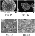
- Fig. 1A and Fig. 1B are scanning electron microscope (SEM) photographs of the first particle and the second particle of Embodiment 1, respectively.
- the first particle may be a spherical or ellipsoidal secondary particle formed by tightly bonding the third particles.
- the second particle may be an irregularly shaped secondary particle stacked by the fourth particles.
- the first particle can include about 150 to about 2000 third particles. In some embodiments, the first particle can include about 600 to about 1000 third particles. In some embodiments, the first particle can include about 700 to about 800 third particles. In some embodiments, the first particle can include about 200, about 500, about 800, about 1000, about 1500 third particles. The third particle has an average particle size of 200 nm to 700 nm.
- the second particle includes the secondary particle composed of 2 to 100 fourth particles. In some embodiments, the second particle can include about 20 to about 90 fourth particles. In some embodiments, the second particle can include about 30 to about 70 fourth particles. In some embodiments, the second particle can include about 40 to about 60 fourth particles. In some embodiments, the second particle can include about 10, about 20, about 30, about 40, about 50, about 80 fourth particles.
- the fourth particle may have an average particle size of about 800 nm to about 5 ⁇ m.
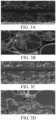
- the second particle is less susceptible to breakage during cycling (as shown in Fig. 2B ) as compared to the first particle which is prone to particle breakage during cycling (as shown in Fig. 2A ).
- the surface of the second particle is smoother than that of the first particle and is easy to slide, thereby improving the slippage between the particles and reducing the internal friction.
- the internal crystal structure of the second particle is less defective, and the stress caused by the lattice change is more easily released during the cycling, which in turn reduces particle breakage.
- the second particle can be filled in the gap of the first particle at the interface, thereby increasing the powder bulk density and reducing the rolling pressure while ensuring the same compaction density, so that the particle breakage is reduced during cold pressing.
- the cathode active material layer is provided such that the second particles are located in a region away from the cathode current collector and the first particles are located in a region close to the cathode current collector.
- the stability of the second particle during the cycle process in combination with the high kinetic performance of the first particle can be achieved, the particle breakage problem can be significantly improved during the cold pressing and cycling of the cathode without the loss of other properties (for example, energy density/DC resistance (DCR)/Rate, etc.), so that the gas production can be delayed during the cycling and the performance of large rate cycling can be improved.
- DCR energy density/DC resistance
- the cathode active material layer includes a first layer and a second layer, wherein the first layer includes the first particle and the second layer includes the second particle.
- the thickness ratio of the second layer to the first layer is 1:10 to 1:1.
- the second layer extends beyond the first layer.
- a peak intensity ratio of the (003) diffraction peak of the X-ray diffraction of the second particle to the first particle is about 1.03 to about 1.6
- the half peak width difference of the (003) diffraction peak of the X-ray diffraction of the first particle and the second particle is about 0.002° to about 0.008°.
- the peak intensity ratio of the (003) diffraction peak of the X-ray diffraction of the second particle to the first particle may be about 1.1 to about 1.5 or about 1.2 to about 1.3.
- the half peak width difference of the (003) diffraction peak of the X-ray diffraction of the first particle and the second particle may be about 0.003° to about 0.007°, about 0.004° to about 0.006°.
- the second particle has a significantly higher crystallinity than the first particle, and thus the peak intensity of the (003) diffraction peak of the X-ray diffraction of the second particle is higher than that of the first particle, and the half peak width of the second particle is narrower than that of the first particle.
- the difference in the peak intensity ratio and the half peak width difference of the (003) diffraction peak of the X-ray diffraction mainly depends on the difference in the mixing ratio of the second particle and the first particle. The higher the proportion of the second particle, the larger the peak intensity ratio of the (003) diffraction peak of the X-ray diffraction, and the larger the half peak width difference.
- the second particle has a large specific surface area (BET), a high DC resistance (DCR), and poor kinetic performance, so that a too large mixing ratio of the second particle would lower the compaction density of the cathode material, seriously affect the dynamic performance of the material, and deteriorate the rate performance, low temperature performance and high temperature performance of the materials, and a too small mixing ratio of the second particle would not achieve the effect of increasing the compaction density of the material and maintaining structural stability.
- BET specific surface area
- DCR high DC resistance
- the desired effect of the present application can be attained.
- the second particle has a molar percentage of Ni of about 30% to about 80%; and the first particle has a molar percentage of Ni of about 50% to about 90%; and the ratio of the molar percentage of Ni in the second particle to the molar percentage of Ni in the first particle is about 1:1 to about 1:3.
- the nickel content of the first lithium-containing transition metal oxide is greater than the nickel content of the second lithium-containing transition metal oxide.
- the nickel content in the second particle in the region away from the cathode current collector of the cathode active material layer is set to be smaller than the nickel content in the first particle in the region close to the cathode current collector, so that the structural stability of the cathode can be further improved, which is advantageous for the long cycle performance of the lithium-ion battery at a large rate.
- the cathode active material layer further includes a conductive agent.
- the conductive agent includes at least one selected from the group consisting of carbon black, carbon nanotube, graphene and derivatives thereof.
- the content of the conductive agent in the region close to the cathode current collector is smaller than the content in the region away from the cathode current collector.
- the content of the conductive agent in the second layer is greater than the content of conductive agent in the first layer.
- the content of the conductive agent in the second layer is about 2% to about 10% based on the total weight of the second layer
- the content of the conductive agent in the first layer is about 1% to about 5% based on the total weight of the first layer
- the ratio of the content of the conductive agent in the second layer to the content of the conductive agent in the first layer is about 1:1 to about 10:1.
- the content of the conductive agent in the active material layer in the region away from the cathode current collector of the cathode is set to be larger than the content of the conductive agent in the active material layer in the region close to the cathode current collector, that is, the amount of the conductive agent is increased for the characteristics of the second particle, the kinetic performance of the second particle can be improved, so that the cathode is more suitable for large rate discharge ( ⁇ 4C).
- the cathode active material layer further includes a binder.
- the binder includes at least one selected from the group consisting of polyvinylidene fluoride, vinylidene fluoride-hexafluoropropylene copolymer, polyamide, polyacrylonitrile, polyacrylate, polyacrylic acid, polyacrylate, sodium carboxymethylcellulose, polyvinyl pyrrolidone, polyvinyl ether, polymethyl methacrylate, polytetrafluoroethylene, polyhexafluoropropylene, butadiene styrene rubber, and epoxy resin.
- the second particle has an average particle size Dv50 that is less than the Dv50 of the first particle, and the second particle has a specific surface area that is greater than the specific surface area of the first particle.
- the ratio of the average particle size of the first particle to the average particle size of the second particle is about 2:1 to about 10:1.
- the second particle has a specific surface area of about 0.30 m 2 /g to about 2.50 m 2 /g, and the first particle has a specific surface area of about 0.1 m 2 /g to about 1.50 m 2 /g, and the ratio of the specific surface area of the second particle to the specific surface area of the first secondary particle is about 1:1 to about 5:1.
- the present application recognizes that the smaller the average particle size (Dv50) of the material, the greater the specific surface area (BET) and the better the kinetic performance. Therefore, the Dv50 of the second particles in the region away from the cathode current collector of the cathode active material layer is set to be smaller than the Dv50 of the first particles in the region close to the cathode current collector, and the specific surface area of the second particle in the region away from the cathode current collector is larger than the specific surface area of the first particle in the region close to the cathode current collector, so that the kinetic performance of the entire cathode active material layer can be remarkably improved, and the long cycling discharge performance of the cathode at a large rate ( ⁇ 4C) can be achieved.
- Dv50 average particle size
- BET specific surface area
- the present application further provides an electrochemical device including a cathode of the present application.
- the electrochemical device is a lithium-ion battery.
- the lithium-ion battery includes a cathode of the present application, an anode, a separator, and an electrolyte, wherein the anode includes an anode active material layer and an anode current collector.
- the cathode current collector of the cathode in some embodiments of the present application may be aluminum foil or nickel foil, and the anode current collector of the anode may be copper foil or nickel foil.
- the cathode current collectors and anode current collectors commonly used in the art may be used.
- the conductive agent and the binder of the anode active material layer are similar to the conductive agent and the binder of the cathode active material layer described above, and will not be described herein.
- the anode active material layer contains an anode active material including, but not limited to, a material selected from the group consisting of a carbon material, a metal compound, an oxide, a sulfide, a nitride of lithium such as LiN 3 , a lithium metal, a metal element and a semi-metal element forming an alloy together with lithium, a polymeric material, and a combination thereof.
- examples of the carbon materials may include low graphitized carbon, easily graphitizable carbon, artificial graphite, natural graphite, mesocarbon microbeads, soft carbon, hard carbon, pyrolytic carbon, coke, vitreous carbon, a sintered body of organic polymer compound, carbon fibers and activated carbon.
- the coke can include pitch coke, needle coke and petroleum coke.
- the organic polymer compound sintered body refers to a material obtained by calcining a polymer material such as phenol plastic or furan resin at an appropriate temperature to carbonize the polymer material, and some of these materials are classified into low graphitized carbon or easily graphitized carbon.
- examples of the polymer material may include polyacetylene and polypyrrole.
- anode active material a material whose charging and discharging voltages are close to those of lithium metal is selected. This is because if the charging and discharging voltages of the anode active material are lower, the battery can more easily have higher energy density.
- the anode active materials can be selected from carbon materials because their crystal structures are only slightly changed upon charging and discharging, so good cycle characteristics and large charging and discharging capacities can be obtained.
- graphite may be selected because it can provide a large electrochemical equivalent and a high energy density.
- the anode active material can include elemental lithium metals, metal elements and semi-metal elements capable of forming alloys together with lithium (Li), alloys and compounds thereof, etc.
- the anode material and the carbon material are used together because in this case, good cycle performance and high energy density can be obtained.
- the alloys used here also include alloys including one or more metal elements and one or more semi-metal elements.
- the alloy may be in a solid solution, a eutectic crystal (eutectic mixture), an intermetallic compound, and a mixture thereof.
- Examples of the metal elements and the semimetal elements may include tin (Sn), lead (Pb), aluminum (Al), indium (In), silicon (Si), zinc (Zn), antimony (Sb), bismuth (Bi), cadmium (Cd), magnesium (Mg), boron (B), gallium (Ga), germanium (Ge), arsenic (As), silver (Ag), zirconium (Zr), yttrium (Y), and hafnium (Hf).
- Examples of the above alloys and compounds may include a material having a chemical formula: Ma s Mb t Li u and a material having a chemical formula: Ma p Mc q Md r .
- Ma denotes at least one of a metal element and a semimetal element capable of forming an alloy with lithium
- Mb denotes at least one of the metal element and the semimetal element other than lithium and Ma
- Mc denotes at least one of the non-metallic elements
- Md represents at least one of the metal element and the semimetal element other than Ma
- s, t, u, p, q, and r satisfy s > 0, t > 0, u > 0, p > 0, q > 0, and r > o.
- an inorganic compound not including lithium (Li) such as Mn02, V 2 O 5 , V 6 O 13 , NiS, and MoS may be used in the anode active material layer.
- the separator of the present application includes, but is not limited to, at least one selected from polyethylene, polypropylene, polyethylene terephthalate, polyimide, and aramid fiber.
- the polyethylene includes at least one component selected from the group consisting of high-density polyethylene, low-density polyethylene and ultrahigh molecular weight polyethylene.
- polyethylene and polypropylene which have a good effect on preventing short circuits, can improve the stability of the lithium-ion battery by the shutdown effect.
- the separator surface may further include a porous layer.
- the porous layer is disposed on at least one surface of the separator.
- the porous layer includes inorganic particles and a binder.
- the inorganic particles are any one or combination of more than one selected from alumina (Al 2 O 3 ), silicon oxide (SiO 2 ), magnesium oxide (MgO), titanium oxide (TiO 2 ), hafnium oxide (HfO 2 ), tin oxide (SnO 2 ), cerium oxide (CeO 2 ), nickel oxide (NiO), zinc oxide (ZnO), calcium oxide (CaO), zirconium dioxide (ZrO 2 ), yttrium oxide (Y 2 O 3 ), silicon carbide (SiC), boehmite, aluminum hydroxide, magnesium hydroxide, calcium hydroxide, and barium sulfate.
- the porous layer can improve heat resistance, oxidation resistance and electrolytic solution wettability of the separator, and enhance the binding properties between the separator and the cathode or anode.
- the lithium-ion battery further includes an electrolyte that may be one or more of a gel electrolyte, a solid electrolyte, and an electrolytic solution, where the electrolytic solution contains a lithium salt and a nonaqueous solvent.
- an electrolyte that may be one or more of a gel electrolyte, a solid electrolyte, and an electrolytic solution, where the electrolytic solution contains a lithium salt and a nonaqueous solvent.
- the lithium salt is selected from one or more of LiPF 6 , LiBF 4 , LiAsF 6 , LiClO 4 , LiB(C 6 H 5 ) 4 , LiCH 3 SO 3 , LiCF 3 SO 3 , LiN(SO 2 CF 3 ) 2 , LiC(SO 2 CF 3 ) 3 , LiSiF 6 , LiBOB, and lithium difluoroborate.
- the lithium salt may be LiPF 6 , because it can provide high ionic conductivity and improve cycle performance.
- the non-aqueous solvent can be a carbonate compound, a carboxylate compound, an ether compound, other organic solvent or a combination thereof.
- the carbonate compound can be a chain carbonate compound, a cyclic carbonate compound, a fluorocarbonate compound or a combination thereof.
- the chain carbonate compound may be dimethyl carbonate (DMC), diethyl carbonate (DEC), dipropyl carbonate (DPC), methyl propyl carbonate (MPC), ethyl propyl carbonate (EPC), methyl ethyl carbonate (MEC), and a combination thereof.
- DMC dimethyl carbonate
- DEC diethyl carbonate
- DPC dipropyl carbonate
- MEC methyl propyl carbonate
- EPC ethyl propyl carbonate
- MEC methyl ethyl carbonate
- cyclic carbonate compound are ethylene carbonate (EC), propylene carbonate (PC), butylene carbonate (BC), vinyl ethylene carbonate (VEC), and a combination thereof.
- the fluorocarbonate compound may be fluoroethylene carbonate (FEC), 1,2-difluoroethylene carbonate, 1,1-difluoroethylene carbonate, 1,1,2-trifluoroethylene carbonate, 1,1,2,2-tetrafluoroethylene carbonate, 1-fluoro-2-methylethylene carbonate, 1-fluoro-1-methylethylene carbonate, 1,2-difluoro-1-methylethylene carbonate, 1,1,2-trifluoro-2-methylethylene carbonate, trifluoromethylethylene carbonate, and a combination thereof.
- FEC fluoroethylene carbonate
- carboxylate compound examples include methyl formate, methyl acetate, ethyl acetate, n-propyl acetate, t-butyl acetate, methyl propionate, ethyl propionate, propyl propionate, ⁇ -butyrolactone, decalactone, valerolactone, mevalonolactone, caprolactone, and a combination thereof.
- ether compound examples include dibutyl ether, tetraethylene glycol dimethyl ether, diethylene glycol dimetyyl ether, 1,2-dimethoxyethane, 1,2-diethoxyethane, ethoxymethoxyethane, 2-methyltetrahydrofuran, tetrahydrofuran, and a combination thereof.
- organic solvents examples include dimethyl sulfoxide, 1,2-dioxolane, sulfolane, methylsulfolane, 1,3-dimethyl-2-imidazolldone, N-methyl-2-pyrrolidone, formamide, dimethyl formamide, acetonitrile, trimethyl phosphate, triethyl phosphate, trioctyl phosphate, phosphate ester, and a combination thereof.
- Such electrochemical devices may include any device for an electrochemical reaction including but not limited to all kinds of primary batteries, secondary batteries, fuel cells, solar cells or capacitors.
- the electrochemical device is a lithium secondary battery, including a lithium metal secondary battery, a lithium-ion secondary battery, a lithium polymer secondary battery or a lithium ion polymer secondary battery.
- the present application further provides an electronic device that can be any device that uses the electrochemical device according to the present application.
- the electronic device include, but is not limited to: a notebook computer, a pen-input computer, a mobile computer, an e-book player, a portable phone, a portable fax machine, a portable copier, a portable printer, a head-mounted stereo headphone, a video recorder, an LCD TV, a portable cleaner, a portable CD player, a mini disc player, a transceiver, an electronic notebook, a calculator, a memory card, a portable recorder, a radio, a backup power source, a motor, a vehicle, a motorcycle, a motorized bicycle, a bicycle, a lighting apparatus, a toy, a game console, a clock, an electric tool, a flash light, a camera, a large battery for household use, or a lithium ion capacitor.
- lithium-ion battery of the present application will be described below by taking a lithium-ion battery as an example in combination with a specific preparation method and test for the prepared lithium-ion battery.
- preparation methods described in the present application are merely exemplary, and any other suitable preparation methods also fall within the protection scope of the present application.
- Example 1 describes a cathode including a first layer having a thickness of about 30 ⁇ m disposed on one surface of a current collector and a second layer having a thickness of about 7.5 ⁇ m disposed on the outside surface of the first layer; wherein the first layer includes a first particle LiNi 0.8 Co 0.09 Mn 0.09 Zr 0.01 Mg 0.01 O 2 , a carbon black conductive agent and a polyvinylidene fluoride binder, the contents of which are respectively about 97.7%, about 1.3% and about 1.0% based on the total weight of the first layer, the second layer includes a second particle LiNi 0.8 Co 0.09 Mn 0.09 Zr 0.01 Mg 0.01 O 2 , a carbon black conductive agent and a polyvinylidene fluoride binder, the contents of which are respectively about 96%, about 2.3%, and about 1.7% based on the total weight of the second layer; wherein the first particle has a Dv50 of about 8.1 ⁇ m and a specific surface area
- a method for preparing a lithium-ion battery is as follows:
- Copper foil was used as the anode current collector, and a layer of graphite slurry was uniformly coated on the surface of the copper foil.
- the slurry was a combination of about 97.7 wt% of artificial graphite, about 1.3 wt% of sodium carboxymethylcellulose (CMC), and about 1.0 wt% of styrene-butadiene rubber (SBR), which was dried at 85°C, and then subjected to cold pressing, cutting, and slitting, and dried under vacuum at 85°C for 4 hours to prepare the anode.
- CMC sodium carboxymethylcellulose
- SBR styrene-butadiene rubber
- EC ethylene carbonate
- DEC diethyl carbonate
- PC polypropylene carbonate
- PP propyl propionate
- VC vinylene carbonate
- a 12 ⁇ m polyethylene (PE) porous polymer film was used as the separator.
- the cathode, the separator, and the anode were stacked in order, so that the separator was between the cathode and anode to play the role of separating, and a wound electrode assembly was obtained by winding. After the electrode assembly was subjected to top side sealing, code spraying, vacuum drying, electrolyte injection and high-temperature standing, a formation and capacity test were performed to obtain the lithium-ion battery.
- Example 2 describes a cathode which differs from the cathode of Example 1 only in that the first particle in the first layer has a Dv50 of about 11.1 ⁇ m and a specific surface area of about 0.411 m 2 /g.
- Example 2 The preparation procedure of Example 2 is basically the same as the preparation procedure of Example 1, except that the first particle satisfying such Dv50 and specific surface area requirements was weighed in step (1) in the preparation of the cathode.
- Example 3 describes a cathode which differs from the cathode of Example 1 only in that the first particle in the first layer has a Dv50 of about 16.3 ⁇ m and a specific surface area of about 0.398 m 2 /g.
- Example 3 The preparation procedure of Example 3 is basically the same as the preparation procedure of Example 1, except that the first particle satisfying such Dv50 and specific surface area requirements was weighed in step (1) in the preparation of the cathode.
- Example 4 describes a cathode which differs from the cathode of Example 1 only in that the first particle in the first layer has a Dv50 of about 26.5 ⁇ m and a specific surface area of about 0.345 m 2 /g.
- Example 4 The preparation procedure of Example 4 is basically the same as the preparation procedure of Example 1, except that the first particle satisfying such Dv50 and specific surface area requirements was weighed in step (1) in the preparation of the cathode.
- Example 5 describes a cathode which differs from the cathode of Example 1 only in that the first particle in the first layer has a Dv50 of about 37.2 ⁇ m and a specific surface area of about 0.279 m 2 /g.
- Example 5 The preparation procedure of Example 5 is basically the same as the preparation procedure of Example 1, except that the first particle satisfying such Dv50 and specific surface area requirements was weighed in step (1) in the preparation of the cathode.
- Example 6 describes a cathode which differs from the cathode of Example 1 only in that the first particle in the first layer has a Dv50 of about 49.6 ⁇ m and a specific surface area of about 0.248 m 2 /g.
- Example 6 The preparation procedure of Example 6 is basically the same as the preparation procedure of Example 1, except that the first particle satisfying such Dv50 and specific surface area requirements was weighed in step (1) in the preparation of the cathode.
- Example 7 describes a cathode which differs from the cathode of Example 2 only in that the second particle in the second layer has a Dv50 of about 0.8 ⁇ m and a specific surface area of about 2.147 m 2 /g.
- Example 7 The preparation procedure of Example 7 is basically the same as the preparation procedure of Example 2, except that the second particle satisfying such Dv50 and specific surface area requirements was weighed in step (2) in the preparation of the cathode.
- Example 8 describes a cathode which differs from the cathode of Example 2 only in that the second particle in the second layer has a Dv50 of about 1.2 ⁇ m and a specific surface area of about 1.840 m 2 /g.
- Example 8 The preparation procedure of Example 8 is basically the same as the preparation procedure of Example 1, except that the second particle satisfying such Dv50 and specific surface area requirements was weighed in step (2) in the preparation of the cathode.
- Example 9 describes a cathode which differs from the cathode of Example 2 only in that the second particle in the second layer has a Dv50 of about 4.2 ⁇ m and a specific surface area of about 0.832 m 2 /g.
- Example 9 The preparation procedure of Example 9 is basically the same as the preparation procedure of Example 1, except that the second particle satisfying such Dv50 and specific surface area requirements was weighed in step (2) of preparation of the second layer slurry in the preparation of the cathode.
- Example 10 describes a cathode which differs from the cathode of Example 2 only in that the second particle in the second layer has a Dv50 of about 6.9 ⁇ m and a specific surface area of about 0.644 m 2 /g.
- Example 10 The preparation procedure of Example 10 is basically the same as the preparation procedure of Example 1, except that the second particle satisfying such Dv50 and specific surface area requirements was weighed in step (2) in the preparation of the cathode.
- Example 11 describes a cathode which differs from the cathode of Example 2 only in that the second particle in the second layer has a Dv50 of about 9.8 ⁇ m and a specific surface area of about 0.487 m 2 /g.
- Example 11 The preparation procedure of Example 11 is basically the same as the preparation procedure of Example 3, except that the second particle satisfying such Dv50 and specific surface area requirements was weighed in step (2) in the preparation of the cathode.
- Example 12 describes a cathode which differs from the cathode of Example 2 only in that the second particle in the second layer has a Dv50 of about 11.0 ⁇ m and a specific surface area of about 0.419 m 2 /g.
- Example 12 The preparation procedure of Example 12 is basically the same as the preparation procedure of Example 3, except that the second particle satisfying such Dv50 and specific surface area requirements was weighed in step (2) in the preparation of the cathode.
- Example 13 describes a cathode which differs from the cathode of Example 2 only in that the thicknesses of the first layer and the second layer are both about 18.75 ⁇ m, that is, the ratio of the thickness of the second layer to the thickness of the first layer is 1:1.
- the preparation procedure of Example 13 is basically the same as the preparation procedure in Example 2, except that the above-mentioned thickness requirements for the first layer and the second layer were achieved by controlling the coating step in step (3) in the preparation of the cathode.
- Example 14 describes a cathode which differs from the cathode of Example 2 only in that the thicknesses of the first layer is about 25.0 ⁇ m and the thicknesses of the second layer is about 12.50 ⁇ m, that is, the ratio of the thickness of the second layer to the thickness of the first layer is 1:2.
- the preparation procedure of Example 14 is basically the same as the preparation procedure in Example 2, except that the above-mentioned thickness requirements for the first layer and the second layer were achieved by controlling the coating step in step (3) in the preparation of the cathode.
- Example 15 describes a cathode which differs from the cathode of Example 2 only in that the thicknesses of the first layer is about 32.16 ⁇ m and the thicknesses of the second layer is about 5.36 ⁇ m, that is, the ratio of the thickness of the second layer to the thickness of the first layer is about 1:6.
- the preparation procedure of the cathode is basically the same as the preparation procedure in Example 3, except that the above-mentioned thickness requirements for the first layer and the second layer were achieved by controlling the coating step in step (3) in the preparation of the cathode.
- Example 16 describes a cathode which differs from the cathode of Example 2 only in that the thicknesses of the first layer is about 33.28 ⁇ m and the thicknesses of the second layer is about 4.16 ⁇ m, that is, the ratio of the thickness of the second layer to the thickness of the first layer is about 1:8.
- Example 16 The preparation procedure of Example 16 is basically the same as the preparation procedure in Example 2, except that the above-mentioned thickness requirements for the first layer and the second layer were achieved by controlling the coating step in step (3) in the preparation of the cathode.
- Example 17 describes a cathode which differs from the cathode of Example 2 only in that the thicknesses of the first layer is about 34.00 ⁇ m and the thicknesses of the second layer is about 3.40 ⁇ m, that is, the ratio of the thickness of the second layer to the thickness of the first layer is about 1:10.
- Example 17 The preparation procedure of Example 17 is basically the same as the preparation procedure in Example 2, except that the above-mentioned thickness requirements for the first layer and the second layer were achieved by controlling the coating step in step (3) in the preparation of the cathode.
- Example 18 describes a cathode which differs from the cathode of Example 2 only in that the active material of the second layer includes the second particles LiNi 0.6 Co 0.2 Mn 0.2 O 2 having a Dv50 of about 6.9 ⁇ m and a specific surface area of about 0.486 m 2 /g.
- Example 18 The preparation procedure of Example 18 is basically the same as the preparation procedure in Example 2, except that the second particle satisfying the above requirements was weighed in step (2) in the preparation of the cathode.
- Example 19 describes a cathode which differs from the cathode of Example 2 only in that the active material of the second layer includes the second particles LiNi 0.5 Co 0.2 Mn 0.3 O 2 having a Dv50 of about 6.9 ⁇ m and a specific surface area of about 0.486 m 2 /g.
- Example 19 The preparation procedure of Example 19 is basically the same as the preparation procedure in Example 2, except that the second particle satisfying the above requirements was weighed in step (2) in the preparation of the cathode.
- Example 20 describes a cathode which differs from the cathode of Example 2 only in that the active material of the first layer includes LiNi 0.6 Co 0.2 Mn 0.2 O 2 .
- Example 20 The preparation procedure of Example 20 is basically the same as the preparation procedure in Example 2, except that the first particle satisfying the above requirements was weighed in step (1) in the preparation of the cathode.
- Example 21 describes a cathode which differs from the cathode of Example 2 only in that the active material of the first layer includes LiNi 0.5 Co 0.2 Mn 0.3 O 2 .
- Example 21 The preparation procedure of Example 21 is basically the same as the preparation procedure in Example 2, except that the first particle satisfying the above requirements was weighed in step (1) in the preparation of the cathode.
- Example 22 describes a cathode which differs from the cathode of Example 2 only in that the content of the conductive agent in the first layer is adjusted to about 1.0%, and the content of the first particle is accordingly adjusted to about 98.0%, the content of the conductive agent in the second layer is adjusted to about 2.1%, and the content of the second particle is accordingly adjusted to about 96.2%.
- Example 22 The preparation procedure of Example 22 is substantially the same as the preparation procedure in Example 2, except that the contents of the active material (i.e., the first or second particle) and the conductive agent weighed in the steps (1) and (2) in the preparation of the cathode were adjusted to meet the above proportion requirements.
- the contents of the active material i.e., the first or second particle
- the conductive agent weighed in the steps (1) and (2) in the preparation of the cathode were adjusted to meet the above proportion requirements.
- Example 23 describes a cathode which differs from the cathode of Example 1 only in that the content of the conductive agent in the second layer is adjusted to about 2.1%, and the content of the second particle is accordingly adjusted to about 96.2%.
- Example 23 The preparation procedure of Example 23 is basically the same as the preparation procedure in Example 2, except that the contents of the second particle and the conductive agent weighed in step (2) in the preparation of the cathode were adjusted to meet the above proportion requirements.
- Example 24 describes a cathode which differs from the cathode of Example 2 only in that the content of the conductive agent in the first layer is adjusted to about 2.4%, and the content of the first particle is accordingly adjusted to about 96.6%, the content of the conductive agent in the second layer is adjusted to about 4.7%, and the content of the second particle is accordingly adjusted to about 93.6%.
- the preparation procedure of the cathode is substantially the same as the preparation procedure in Example 2, except that the contents of the active material (i.e., the first or second particle) and the conductive agent weighed in the steps (1) and (2) in the preparation of the cathode were adjusted to meet the above proportion requirements.
- Example 25 describes a cathode which differs from the cathode of Example 2 only in that the content of the conductive agent in the first layer is adjusted to about 3.7%, and the content of the first particle is accordingly adjusted to about 95.3%, the content of the conductive agent in the second layer is adjusted to about 6.3%, and the content of the second particle is accordingly adjusted to about 92.0%.
- Example 25 The preparation procedure of Example 25 is substantially the same as the preparation procedure in Example 2, except that the contents of the active material (i.e., the first or second particle) and the conductive agent weighed in the steps (1) and (2) in the preparation of the cathode were adjusted to meet the above proportion requirements.
- Example 26 describes a cathode which differs from the cathode of Example 2 only in that the content of the conductive agent in the first layer is adjusted to about 4.9%, and the content of the first particle is accordingly adjusted to about 94.1%, the content of the conductive agent in the second layer is adjusted to about 9.8%, and the content of the second particle is accordingly adjusted to about 88.5%.
- Example 26 The preparation procedure of Example 26 is substantially the same as the preparation procedure in Example 2, except that the contents of the active material (i.e., the first or second particle) and the conductive agent weighed in the steps (1) and (2) in the preparation of the cathode were adjusted to meet the above proportion requirements.
- the contents of the active material i.e., the first or second particle
- the conductive agent weighed in the steps (1) and (2) in the preparation of the cathode were adjusted to meet the above proportion requirements.
- Example 27 describes a cathode which differs from the cathode of Example 2 only in that the cathode active material layer has a 4-layer structure, and a first slurry coating layer, a second slurry coating layer, a first slurry coating layer, and a second slurry coating layer were disposed on the surface of the cathode current collector in order.
- Example 27 The preparation procedure of Example 27 is substantially the same as the preparation procedure in Example 2, except that the first layer slurry and the second layer slurry were alternately coated in step (3) in the preparation of the cathode to obtain the above cathode active material layer having a 4-layer structure.
- Example 28 describes a cathode which differs from the cathode of Example 2 only in that the cathode active material layer has a 6-layer structure, and a first slurry coating layer, a second slurry coating layer, a first slurry coating layer, a second slurry coating layer, a first slurry coating layer and a second slurry coating layer are disposed on the surface of the cathode current collector in order.
- Example 28 The preparation procedure of Example 28 is substantially the same as the preparation procedure in Example 2, except that the first layer slurry and the second layer slurry were alternately coated in step (3) in the preparation of the cathode to obtain the above cathode active material layer having a 6-layer structure.
- Example 29 describes a cathode which differs from the cathode of Example 2 only in that the first layer is formed by coating a slurry of a mixture of the first particle and the second particle, wherein the mass ratio of the first particle to the second particle is 9:1.
- Example 29 The preparation procedure of Example 29 is basically the same as the preparation procedure in Example 2, except that the active material weighed in step (1) in the preparation of the cathode was the first particle and the second particle satisfying the mass ratio of 9:1 to prepare the first slurry layer.
- Comparative Example 1 describes a cathode which differs from the cathode in Example 1 only in that the cathode of Comparative Example 1 only has the second layer in Example 1, and the thickness of the second layer is about 37.5 ⁇ m, the second particle contained therein has a Dv50 of about 2.3 ⁇ m and a specific surface area of about 1.040 m 2 /g, that is, the active material layer of the cathode of Comparative Example 1 only has the second particle.
- Comparative Example 1 The preparation procedure of Comparative Example 1 is substantially the same as that in Example 1, except that Comparative Example 1 did not have the steps associated with the first particle in Example 1.
- Comparative Example 2 describes a cathode which differs from the cathode of Example 1 only in that the cathode of Comparative Example 2 only has the first layer in Example 1, and the thickness of the first layer is about 37.5 ⁇ m, that is, the active material layer of the cathode of Comparative Example 2 only has the first particle.
- Comparative Example 2 The preparation procedure of Comparative Example 2 is substantially the same as that in Example 1, except that Comparative Example 2 did not have the steps associated with the second particle in Example 1.
- the present application uses a Malvern particle size tester to measure the particle size of the material: the material was dispersed in a dispersant (ethanol), and after 30 minutes of sonication, the sample was added to the Malvern particle size tester to start the test.
- Dv50 means a particle size with which the volume cumulative frequency from the smaller diameter side reaches 50% in the volume-based particle size distribution, that is, the average particle size.
- the present application measures the specific surface area of the material by the BET test method (Brunauer-Emmett-Teller, BET).
- Tri Star 11 surface analyzer was used, about 3 g to about 6 g of sample was loaded in a sample tube, then the sample was placed in a degassing station, heated and vacuumed, then the heating and vacuuming were stopped to lower the sample temperature to room temperature, the sample was removed to measure the weight of the sample and the sample tube, and then loaded into an analysis station for analysis, data processing and calculation.
- a scanning electron microscope is used for obtaining a morphological structure of a sample through mutual effect of an electron beam and the sample and by using secondary electron signal for imaging.
- An SEM used in the present application was JSM-6360LV SEM of JEOL Company and a matched X-ray energy spectrometer, which were used for analyzing the morphological structure and element distribution of the sample.
- the SEM image of a cross section of a pole piece refers to the cross-section pretreatment of the pole piece before the SEM testing.
- the pretreatment method in the present application is Cross Section Polisher (CP), which uses ion beam cutting to cut out the profile of the sample. Unlike general sample profile polishing, ion beam cutting avoids the effects of stresses caused by the polishing process. When shooting, the pole piece should be as flat as possible and parallel to the test bench.
- CP Cross Section Polisher
- the lithium-ion battery to be tested was allowed to stand at a test temperature of about 45°C for about 2 hours.
- the lithium-ion battery was charged at a constant current of about 2 C to about 4.2 V, then charged at a constant voltage of about 4.2 V to about 0.02 C, and allowed to stand for about 15 minutes; then the lithium-ion battery was discharged at a constant current of about 8 C to about 2.8 V, and allowed to stand for about 30 minutes.
- the above procedure was repeated 500 times to record the discharge capacity at this time.
- the thickness of the lithium-ion battery after 500 cycles was tested using a thickness measuring device, and the thickness variation after 500 cycles was recorded.
- Table 1 below shows in detail the expansion ratio and capacity retention ratio of the lithium-ion batteries of Examples 1-29 and Comparative Examples 1-2 after 500 cycles at about the rate of 8 C.
- Table 1 Expansion ratio Capacity retention ratio
- Example 1 9.0% 82.9%
- Example 2 9.0% 84.4%
- Example 3 8.1% 83.4%
- Example 4 8.7% 83.2%
- Example 5 9.2% 82.7%
- Example 6 9.6% 79.8%
- Example 7 8.2% 84.5%
- Example 9 8.3 % 84.1%
- Example 10 8.4% 84.3%
- Example 11 9.8% 80.2%
- Example 12 10.0% 79.9%
- Example 13 11.3%
- Example 14 10.4% 82.7%
- Example 15 12.6% 81.8%
- Example 16 16.2% 76.3%
- Example 17 18.7% 71.2%
- Example 18 7.7% 86.7%
- Example 19 7.5%
- Example 21 7.2% 89.2%
- Example 22 8.6% 80.
- Comparative Example 1 the measured expansion rate was relatively low due to the inability to charge and discharge effectively; and due to the characteristics of the second particle, the capacity retention rate dropped to 3% in the first cycle of discharge, and dropped to 0% after several cycles.
- the expansion ratios of the cathode plate in Example 1 before the cycle and after the SOOth cycle at about the rate of 8 C are significantly lower than that of the cathode in Comparative Example 2.
- the cathode in Example 1 has a lower expansion rate with cycling than the cathode in Comparative Example 2, and this tendency becomes more pronounced as the number of cycle increases. This is mainly because the second particle is not easy to break during the cycling, and the first particle has small polarization and good rate performance.
- the advantages of the two can be combined, the bulk density of the cathode material is increased, the particle breakage in the cold press overcharge is reduced, and the gas production during long cycle at large rate is reduced, thereby achieving the effect of a long cycle at a large rate.
- Examples 1-6 adjust the size of the Dv50 of the first particle, respectively. It can be seen from the analysis that the cycle expansion rate and the cycle capacity retention rate of the lithium-ion battery first improve and then decrease as the Dv50 of the first particle increases. This is mainly because as the Dv50 of the first particle increases, the specific surface area decreases correspondingly, and the kinetic performance deteriorates, however, when the Dv50 is too small, the side reaction increases. According to the study of the present application, when the first particle has a Dv50 between about 5 ⁇ m and about 20 ⁇ m, lithium-ion batteries can achieve optimal comprehensive performance between kinetic performance and side reactions.
- Example 2 and Examples 13-17 adjust the thickness ratio of the second layer to the first layer, respectively. It can be seen from the analysis that the cycle expansion ratio and the cycle capacity retention rate of the lithium-ion battery gradually improve as the thickness ratio of the second layer to the first layer decreases. This is mainly because the mixing ratio of the second particle to the first particle can be controlled by adjusting the thickness ratio of the first layer to the second layer. When the mixing ratio of the second particle to the first particle is proper, the second particle can be utilized to increase the compaction density of the material and maintain the structural stability of the material, and the excellent dynamic properties of the first particle can be utilized to improve the cycle life and cycle expansion rate of the lithium-ion battery at a large rate.
- Example 2 and Examples 18-19 adjust the molar percentage of Ni in the second layer, respectively. It can be seen from the analysis that the cycle expansion ratio and cycle capacity retention rate of the lithium-ion battery gradually improve as the Ni content decreases. This is mainly because with a lower Ni content, the better the thermal stability and the better the cycle performance.
- Example 2 and Examples 20-21 respectively adjust the molar percentage of Ni in the first layer, a similar conclusion can be obtained therefrom. Therefore, in some Examples, the nickel content of the second layer (i.e., the outermost layer) of the cathode is set to be smaller than the nickel content of the first layer (i.e., the inner layer) to further improve the structural stability of the outermost layer and improve the cycle life of the lithium-ion battery at a large rate.
- the molar percentage of Ni in the cathode active material of the outermost layer is about 30% to about 80%. In some Examples of the present application, the molar percentage of Ni in the lithium-containing transition metal oxide of the inner layer is about 50% to about 90%. In some Examples of the present application, the ratio of the weight of Ni in the cathode active material of the outermost layer to the weight of Ni in the lithium-containing transition metal oxide of the inner layer is about 1:1 to about 1:10.
- Example 2 and Examples 22-25 adjust the content of the conductive agent in the first layer and the second layer, respectively. It can be seen from the analysis that the cycle expansion rate and the cycle capacity retention rate of the lithium-ion battery gradually improve as the content of the conductive agent increases. This is mainly because as the content of the conductive agent increases, the kinetic performance is better, and the large-rate discharge is more favorable, thereby improving the cycle life of the lithium-ion battery at a large rate. However, as the content of the conductive agent further increases, the active material is reduced, and thus the energy density is lowered, and therefore, comprehensive consideration is required.
- the second particle has a large polarization and poor kinetic performance, and therefore, in some Examples, the cathode is designed such that the content of the conductive agent in the region close to the cathode current collector is less than the content of the conductive agent in the region away from the cathode current collector in order to improve the kinetic performance of the second particle, so that the cathode is more suitable for large-rate discharge ( ⁇ 4 C).
- Example 2 and Examples 27-28 are arrangements of different layers, wherein the cathode active material layer of Example 2 is a two-layer structure coated with a first slurry layer (which contains the first particle) and a second slurry layer (which contains the second particle).
- Example 27 is a 4-layer structure in which a first slurry layer and a second slurry layer are alternately coated
- Example 28 is a 6-layer structure in which a first slurry layer and a second slurry layer are alternately coated. It can be seen from the analysis that the multilayer alternating cathode active material layer formed by the first particle and the second particle can improve the cycle expansion ratio and the cycle capacity retention rate of the lithium-ion battery.
- the interface of the first particle/second particle increases as the number of alternating layers of the first particle/second particle increases, and at the interface, small particles can fill in the gaps around the large particles, thereby increasing the powder bulk density and reducing any rolling pressure while ensuring the same compaction density, so that particle breakage is reduced during cold pressing.
- Examples 2 and 29 respectively adjust the composition of the first layer, wherein the first layer of Example 2 is a single layer structure formed of the first particle, and the first layer of Example 29 is a single layer structure formed by the slurry of the mixture of the first particle and the second particle.
- the first coating to the first particle/second particle mixture can significantly improve the cycle expansion rate and the cycle capacity retention rate of the lithium-ion battery. This is mainly because in the first particle/second particle mixture, the first particle/second particle interface increases, and at the interface, small particles can fill in the gaps around the large particles, thereby increasing the powder bulk density and reducing any rolling pressure while ensuring the same compaction density, so that particle breakage is reduced during cold pressing.
- the mixing weight ratio of the first particle to the second particle is 9:1, but the present application is not limited thereto, and mixtures having other ratios have similar conclusions.
- the present application provides a simple and suitable method for the industrial production of preparing a cathode and an electrochemical device having high rate performance.
Landscapes
- Chemical & Material Sciences (AREA)
- Chemical Kinetics & Catalysis (AREA)
- Electrochemistry (AREA)
- General Chemical & Material Sciences (AREA)
- Inorganic Chemistry (AREA)
- Composite Materials (AREA)
- Engineering & Computer Science (AREA)
- Materials Engineering (AREA)
- Manufacturing & Machinery (AREA)
- Battery Electrode And Active Subsutance (AREA)
Claims (13)
- Kathode, dadurch gekennzeichnet, dass die Kathode umfasst:einen Kathodenstromkollektor; undeine Schicht aus kathodenaktivem Material, die auf einer Oberfläche des Kathodenstromkollektors angeordnet ist, wobei die Schicht aus kathodenaktivem Material ein erstes Partikel und ein zweites Partikel umfasst, wobei das erste Partikel ein erstes sekundäres Partikel umfasst, das aus einem dritten Partikel besteht, wobei das dritte Partikel ein erstes primäres Partikel ist, wobei das erste Partikel eine durchschnittliche Partikelgröße von 5 µm bis 20 µm aufweist, wobei das dritte Partikel eine durchschnittliche Partikelgröße von 200 nm bis 700 nm aufweist, wobei das zweite Partikel ein viertes Partikel und/oder ein aus dem vierten Partikel bestehendes zweites sekundäres Partikel umfasst, wobei das vierte Partikel ein zweites primäres Partikel ist, wobei das zweite Partikel eine durchschnittliche Partikelgröße von 3 µm bis 5 µm aufweist, wobei das vierte Partikel eine durchschnittliche Partikelgröße von 800 nm bis 5 µm aufweist,wobei die durchschnittlichen Partikelgrößen unter Verwendung eines Malvern-Partikelgrößenprüfgeräts nach 30 Minuten Beschallung eines zu prüfenden dispergierten Materials gemessen werden und einer Partikelgröße entsprechen, bei der die Volumen-Summenhäufigkeit von der Seite des kleineren Durchmessers 50 % in der volumenbezogenen Partikelgrößenverteilung erreicht,wobei ein Bereich, der das erste Partikel enthält, sich näher am Kathodenstromkollektor befindet als der Bereich, der das zweite Partikel enthält.
- Kathode nach Anspruch 1, wobei die Schicht aus kathodenaktivem Material eine erste Schicht und eine zweite Schicht umfasst, wobei die erste Schicht das erste Partikel umfasst und wobei die zweite Schicht das zweite Partikel umfasst.
- Kathode nach einem der Ansprüche 1 oder 2, wobei in einer Dickenrichtung der Schicht aus kathodenaktivem Material eine Konzentration des zweiten Partikels mit der abnehmenden Entfernung vom Kathodenstromkollektor abnimmt und eine Konzentration des ersten Partikels mit der abnehmenden Entfernung vom Kathodenstromkollektor zunimmt.
- Kathode nach einem der Ansprüche 1 bis 3, wobei das erste Partikel ein erstes sekundäres Partikel umfasst, das aus 150 bis 2000 dritten Partikeln besteht, und das zweite Partikel das zweite sekundäre Partikel umfasst, das aus 2 bis 100 vierten Partikeln besteht.
- Kathode nach Anspruch 2, wobei ein Dickenverhältnis der zweiten Schicht zur ersten Schicht 1:10 bis 1:1 beträgt.
- Kathode nach einem der Ansprüche 1 bis 5, wobei die Schicht aus kathodenaktivem Material weiter ein leitfähiges Mittel umfasst, wobei eine Konzentration des leitfähigen Mittels mit der abnehmenden Entfernung vom Kathodenstromkollektor abnimmt.
- Kathode nach einem der Ansprüche 1 bis 6, wobei das erste Partikel eine spezifische Oberfläche von 0,10 m2/g bis 1,50 m2/g aufweist und das zweite Partikel eine spezifische Oberfläche von 0,30 m2/g bis 2,50 m2/g aufweist, wobei ein Verhältnis der spezifischen Oberfläche des zweiten Partikels zur spezifischen Oberfläche des ersten Partikels 1:1 bis 5:1 beträgt, wobei die spezifische Oberfläche nach dem Brunauer-Emmett-Teller-Prüfverfahren gemessen wird.
- Kathode nach einem der Ansprüche 1 bis 7, wobei ein Spitzenintensitätsverhältnis der (003)-Beugungsspitze der Röntgenbeugung des zweiten Partikels zum ersten Partikel 1,03 bis 1,6 beträgt und eine Differenz der halben Spitzenbreite der (003)-Beugungsspitze der Röntgenbeugung des ersten Partikels und des zweiten Partikels 0,002° bis 0,008° beträgt.
- Kathode nach einem der Ansprüche 1 bis 8, wobei ein Verhältnis einer durchschnittlichen Partikelgröße des ersten Partikels zu einer durchschnittlichen Partikelgröße des zweiten Partikels 2:1 bis 10:1 beträgt.
- Kathode nach einem der Ansprüche 1 bis 9, wobei
das erste Partikel ein erstes lithiumhaltiges Übergangsmetalloxid ist, das eine chemische Formel LiαNixCoyM1zN1βO2 aufweist, wobei 0,95<a<1,05, 0,5<x<l, 0<y<0,4, 0<z<0,4, 0≤β≤0,05, und x+y+z+β=1, wobei M1 mindestens eines ist, ausgewählt aus der Gruppe bestehend aus Mn und Al, und N1 mindestens eines ist, ausgewählt aus der Gruppe bestehend aus Mg, Ti, Zr, Nb, Y, Cr, V, Ge, Mo und Sr; wobei das zweite Partikel ein zweites lithiumhaltiges Übergangsmetalloxid ist, das eine chemische Formel LinNiaCobM2cN2dO2 aufweist, wobei 0,95<n<1,05, 0,3<a<l, 0<b<0,4, 0<c<0,4, 0≤d≤0,02, und a+b+c+d=1, wobei M2 mindestens eines ist, ausgewählt aus der Gruppe bestehend aus Mn und Al; und N2 mindestens eines ist, ausgewählt aus der Gruppe bestehend aus Mg, Ti, Zr, Nb, Y, Cr, V, Ge, Mo und Sr. - Kathode nach Anspruch 10, wobei ein Nickelgehalt des ersten lithiumhaltigen Übergangsmetalloxids größer ist als ein Nickelgehalt des zweiten lithiumhaltigen Übergangsmetalloxids.
- Kathode nach Anspruch 2, wobei sich die zweite Schicht an einem Rand der Schicht aus kathodenaktivem Material über die erste Schicht hinaus erstreckt.
- Elektrochemische Vorrichtung, umfassend:eine Anode;einen Separator;einen Elektrolyten; unddie Kathode nach einem der Ansprüche 1 bis 12.
Applications Claiming Priority (2)
| Application Number | Priority Date | Filing Date | Title |
|---|---|---|---|
| CN201910655730.8A CN110429252B (zh) | 2019-07-19 | 2019-07-19 | 正极及电化学装置 |
| PCT/CN2020/091800 WO2021012768A1 (en) | 2019-07-19 | 2020-05-22 | Cathode and electrochemical device |
Publications (3)
| Publication Number | Publication Date |
|---|---|
| EP3844830A1 EP3844830A1 (de) | 2021-07-07 |
| EP3844830A4 EP3844830A4 (de) | 2022-06-08 |
| EP3844830B1 true EP3844830B1 (de) | 2024-09-18 |
Family
ID=68411197
Family Applications (1)
| Application Number | Title | Priority Date | Filing Date |
|---|---|---|---|
| EP20843081.9A Active EP3844830B1 (de) | 2019-07-19 | 2020-05-22 | Kathode und elektrochemische vorrichtung |
Country Status (10)
| Country | Link |
|---|---|
| US (1) | US12142753B2 (de) |
| EP (1) | EP3844830B1 (de) |
| JP (1) | JP7261881B2 (de) |
| CN (1) | CN110429252B (de) |
| DK (1) | DK3844830T3 (de) |
| ES (1) | ES3004581T3 (de) |
| FI (1) | FI3844830T3 (de) |
| HU (1) | HUE070067T2 (de) |
| PL (1) | PL3844830T3 (de) |
| WO (1) | WO2021012768A1 (de) |
Families Citing this family (29)
| Publication number | Priority date | Publication date | Assignee | Title |
|---|---|---|---|---|
| CN110429252B (zh) * | 2019-07-19 | 2020-11-27 | 宁德新能源科技有限公司 | 正极及电化学装置 |
| CN114402459B (zh) * | 2019-11-15 | 2024-07-12 | 日本汽车能源株式会社 | 锂离子二次电池用正极和锂离子二次电池 |
| KR20220098800A (ko) * | 2020-01-21 | 2022-07-12 | 닝더 엠프렉스 테크놀로지 리미티드 | 양극 물질과 이를 포함하는 전기화학 장치 및 전자 장치 |
| CN113193186B (zh) * | 2020-03-20 | 2025-05-30 | 宁德新能源科技有限公司 | 正极活性材料、电化学装置和电子装置 |
| WO2022051991A1 (zh) * | 2020-09-10 | 2022-03-17 | 宁德时代新能源科技股份有限公司 | 电极活性组合物及其制备方法及电极、电池和装置 |
| JP7213215B2 (ja) * | 2020-10-12 | 2023-01-26 | プライムプラネットエナジー&ソリューションズ株式会社 | 非水電解質二次電池 |
| CN112467078B (zh) * | 2020-11-30 | 2022-06-17 | 宁德新能源科技有限公司 | 电化学装置和电子装置 |
| CN114614106B (zh) * | 2020-12-17 | 2024-03-12 | 宁德新能源科技有限公司 | 电化学装置和电子装置 |
| KR102810334B1 (ko) * | 2021-01-08 | 2025-05-21 | 주식회사 엘지에너지솔루션 | 양극 및 이를 포함하는 리튬 이차전지 |
| CN117543003B (zh) * | 2021-01-13 | 2025-12-12 | 宁德新能源科技有限公司 | 正极材料、电化学装置以及用电设备 |
| JP7273869B2 (ja) * | 2021-01-21 | 2023-05-15 | プライムプラネットエナジー&ソリューションズ株式会社 | 非水電解質二次電池 |
| KR102711992B1 (ko) | 2021-01-29 | 2024-10-02 | 주식회사 엘지에너지솔루션 | 양극 및 이를 포함하는 리튬 이차전지 |
| JP7416734B2 (ja) | 2021-02-05 | 2024-01-17 | プライムプラネットエナジー&ソリューションズ株式会社 | 非水電解質二次電池 |
| JP7262500B2 (ja) * | 2021-03-18 | 2023-04-21 | プライムプラネットエナジー&ソリューションズ株式会社 | 正極および非水電解質二次電池 |
| JP7399904B2 (ja) * | 2021-03-31 | 2023-12-18 | プライムプラネットエナジー&ソリューションズ株式会社 | 正極およびこれを備える非水電解液二次電池 |
| JP7271595B2 (ja) * | 2021-04-09 | 2023-05-11 | プライムプラネットエナジー&ソリューションズ株式会社 | 正極およびこれを備える二次電池 |
| CN113363417A (zh) * | 2021-06-25 | 2021-09-07 | 东莞新能安科技有限公司 | 电化学装置和电子装置 |
| KR102933855B1 (ko) * | 2021-06-28 | 2026-03-03 | 주식회사 엘지에너지솔루션 | 리튬 이차 전지용 양극 및 이를 구비하는 리튬 이차 전지 |
| WO2023283960A1 (zh) * | 2021-07-16 | 2023-01-19 | 宁德时代新能源科技股份有限公司 | 正极极片、二次电池及其制备方法与包含该二次电池的电池模块、电池包和用电装置 |
| JP7443310B2 (ja) * | 2021-09-28 | 2024-03-05 | プライムプラネットエナジー&ソリューションズ株式会社 | 正極およびリチウムイオン二次電池 |
| KR102605558B1 (ko) * | 2022-01-07 | 2023-11-22 | 에스케이온 주식회사 | 리튬 이차 전지용 양극 및 이를 포함하는 리튬 이차 전지 |
| CN118679602A (zh) * | 2022-02-15 | 2024-09-20 | 株式会社Lg新能源 | 正极材料以及包含该正极材料的正极和锂二次电池 |
| KR20230168282A (ko) * | 2022-06-02 | 2023-12-13 | 컨템포러리 엠퍼렉스 테크놀로지 씨오., 리미티드 | 리튬 이온 전지용 양극판, 이를 포함하는 리튬 이온 전지 및 전기 장치 |
| CN114883521B (zh) * | 2022-06-29 | 2022-10-18 | 比亚迪股份有限公司 | 一种二次电池极片及其制备方法和二次电池 |
| US20260031325A1 (en) * | 2022-09-01 | 2026-01-29 | Vehicle Energy Japan Inc. | Lithium ion secondary battery positive electrode and lithium ion secondary battery |
| EP4579850A4 (de) * | 2022-12-31 | 2026-03-04 | Ningde Amperex Technology Ltd | Elektrochemische vorrichtung und elektronische vorrichtung damit |
| CN116646465A (zh) * | 2023-06-06 | 2023-08-25 | 浙江锂威能源科技有限公司 | 极片 |
| CN116799143A (zh) * | 2023-06-28 | 2023-09-22 | 宁波容百新能源科技股份有限公司 | 一种正极片和电池 |
| KR20260006959A (ko) * | 2024-07-05 | 2026-01-13 | 삼성에스디아이 주식회사 | 양극 및 이를 포함하는 리튬 이차 전지 |
Family Cites Families (16)
| Publication number | Priority date | Publication date | Assignee | Title |
|---|---|---|---|---|
| WO2005018027A1 (ja) | 2003-08-19 | 2005-02-24 | Seimi Chemical Co., Ltd. | リチウム二次電池用正極材料およびその製造方法 |
| JP4455008B2 (ja) * | 2003-10-28 | 2010-04-21 | 株式会社東芝 | 非水電解質二次電池 |
| JP2009026599A (ja) | 2007-07-19 | 2009-02-05 | Toyota Motor Corp | 正電極板、リチウムイオン二次電池、車両、および、電池搭載機器 |
| JP4972624B2 (ja) * | 2008-09-30 | 2012-07-11 | 日立ビークルエナジー株式会社 | リチウム二次電池用正極材料及びそれを用いたリチウム二次電池 |
| WO2011109815A1 (en) * | 2010-03-05 | 2011-09-09 | A123 Systems, Inc. | Design and fabrication of electrodes with gradients |
| US20170050864A1 (en) * | 2011-05-30 | 2017-02-23 | Sumitomo Metal Mining Co., Ltd. | Positive electrode active material for nonaqueous secondary batteries, method for producing same, and nonaqueous electrolyte secondary battery using positive electrode active material |
| JP5807749B2 (ja) | 2011-12-08 | 2015-11-10 | ソニー株式会社 | 非水電解液二次電池用正極、非水電解液二次電池、電池パック、電動車両、電力貯蔵システム、電動工具および電子機器 |
| CN102751485B (zh) | 2012-07-17 | 2015-09-16 | 中国电子科技集团公司第十八研究所 | 锂离子电池用复合正极材料的制备方法 |
| JP6136612B2 (ja) * | 2013-06-14 | 2017-05-31 | ソニー株式会社 | リチウムイオン二次電池用電極、リチウムイオン二次電池、電池パック、電動車両、電力貯蔵システム、電動工具および電子機器 |
| KR101619604B1 (ko) * | 2013-09-26 | 2016-05-10 | 주식회사 엘지화학 | 전극조립체 및 이차전지의 제조방법 |
| JP6531652B2 (ja) * | 2014-01-31 | 2019-06-19 | 三洋電機株式会社 | 非水電解質二次電池用負極 |
| CN103811744B (zh) | 2014-02-13 | 2016-09-21 | 北大先行科技产业有限公司 | 一种锂离子电池三元正极材料的制备方法 |
| CN105161710A (zh) | 2015-08-31 | 2015-12-16 | 宁波金和锂电材料有限公司 | 一种电池正极材料及其制备方法和锂离子电池 |
| JP6528666B2 (ja) * | 2015-12-09 | 2019-06-12 | 株式会社村田製作所 | 正極活物質、正極、電池、電池パック、電子機器、電動車両、蓄電装置および電力システム |
| KR102062689B1 (ko) | 2016-11-23 | 2020-01-06 | 주식회사 엘지화학 | 이차전지용 양극 및 이를 포함하는 리튬 이차전지 |
| CN110429252B (zh) | 2019-07-19 | 2020-11-27 | 宁德新能源科技有限公司 | 正极及电化学装置 |
-
2019
- 2019-07-19 CN CN201910655730.8A patent/CN110429252B/zh active Active
-
2020
- 2020-05-22 PL PL20843081.9T patent/PL3844830T3/pl unknown
- 2020-05-22 FI FIEP20843081.9T patent/FI3844830T3/fi active
- 2020-05-22 DK DK20843081.9T patent/DK3844830T3/da active
- 2020-05-22 WO PCT/CN2020/091800 patent/WO2021012768A1/en not_active Ceased
- 2020-05-22 HU HUE20843081A patent/HUE070067T2/hu unknown
- 2020-05-22 US US16/964,746 patent/US12142753B2/en active Active
- 2020-05-22 EP EP20843081.9A patent/EP3844830B1/de active Active
- 2020-05-22 JP JP2021530099A patent/JP7261881B2/ja active Active
- 2020-05-22 ES ES20843081T patent/ES3004581T3/es active Active
Also Published As
| Publication number | Publication date |
|---|---|
| JP2022515014A (ja) | 2022-02-17 |
| FI3844830T3 (fi) | 2024-11-28 |
| EP3844830A4 (de) | 2022-06-08 |
| WO2021012768A1 (en) | 2021-01-28 |
| PL3844830T3 (pl) | 2025-02-10 |
| ES3004581T3 (en) | 2025-03-12 |
| DK3844830T3 (da) | 2024-11-18 |
| JP7261881B2 (ja) | 2023-04-20 |
| US12142753B2 (en) | 2024-11-12 |
| CN110429252A (zh) | 2019-11-08 |
| US20210313563A1 (en) | 2021-10-07 |
| EP3844830A1 (de) | 2021-07-07 |
| HUE070067T2 (hu) | 2025-05-28 |
| CN110429252B (zh) | 2020-11-27 |
Similar Documents
| Publication | Publication Date | Title |
|---|---|---|
| EP3844830B1 (de) | Kathode und elektrochemische vorrichtung | |
| US20260031353A1 (en) | Negative electrode active material and preparation method thereof, secondary battery, and electronic device | |
| KR101787199B1 (ko) | 리튬 이차전지용 양극활물질, 이의 제조방법 및 이를 포함하는 리튬 이차전지 | |
| US20240162440A1 (en) | Negative electrode, electrochemical apparatus, and electronic apparatus | |
| CN115050923B (zh) | 电化学装置和电子装置 | |
| KR102849565B1 (ko) | 양극 활물질 및 이를 포함하는 리튬 이차전지 | |
| EP4123760A1 (de) | Negativelektrodenaktivmaterial, elektrochemische vorrichtung damit und elektronische vorrichtung | |
| EP3968415B1 (de) | Negativelektroden-aktivmaterial und elektrochemische vorrichtung sowie elektronische vorrichtung damit | |
| KR20160040116A (ko) | 리튬 이차전지용 양극활물질, 이의 제조방법 및 이를 포함하는 리튬 이차전지 | |
| KR20210096557A (ko) | 양극 물질과 상기 양극 물질을 포함하는 전기화학 장치 및 전자 장치 | |
| US11476456B2 (en) | Lithium cobalt-based positive electrode active material, preparation method thereof, positive electrode and secondary battery including the same | |
| EP3879600A1 (de) | Kathodenmaterial, elektrochemische vorrichtung und elektronische vorrichtung damit | |
| US20200227741A1 (en) | Cathode material and electrochemical device including cathode material | |
| CN113066961A (zh) | 负极极片、电化学装置和电子装置 | |
| CN113196524A (zh) | 负极材料、负极极片、电化学装置和电子装置 | |
| US20230246185A1 (en) | Positive electrode, electrochemical apparatus, and electronic apparatus | |
| WO2023122855A1 (zh) | 一种电化学装置和电子装置 | |
| EP4270532A1 (de) | Polstück für negative elektrode, elektrochemische vorrichtung damit und elektronische vorrichtung | |
| KR20200116869A (ko) | 음극 활물질, 이의 제조방법, 이를 포함하는 음극 및 이차전지 | |
| EP4485564A1 (de) | Negativelektrode und elektrochemische vorrichtung und elektronische vorrichtung damit | |
| EP4546453A1 (de) | Elektrochemische vorrichtung und elektronische vorrichtung damit | |
| US20250273664A1 (en) | Negative electrode plate, battery, and electric apparatus | |
| EP4546465A1 (de) | Elektrochemische vorrichtung und elektronische vorrichtung damit | |
| US20240347694A1 (en) | Electrochemical device and electronic device | |
| KR20250130563A (ko) | 양극 활물질 및 이를 포함하는 리튬 이차전지 |
Legal Events
| Date | Code | Title | Description |
|---|---|---|---|
| STAA | Information on the status of an ep patent application or granted ep patent |
Free format text: STATUS: THE INTERNATIONAL PUBLICATION HAS BEEN MADE |
|
| STAA | Information on the status of an ep patent application or granted ep patent |
Free format text: STATUS: REQUEST FOR EXAMINATION WAS MADE |
|
| PUAI | Public reference made under article 153(3) epc to a published international application that has entered the european phase |
Free format text: ORIGINAL CODE: 0009012 |
|
| 17P | Request for examination filed |
Effective date: 20210330 |
|
| AK | Designated contracting states |
Kind code of ref document: A1 Designated state(s): AL AT BE BG CH CY CZ DE DK EE ES FI FR GB GR HR HU IE IS IT LI LT LU LV MC MK MT NL NO PL PT RO RS SE SI SK SM TR |
|
| RAP3 | Party data changed (applicant data changed or rights of an application transferred) |
Owner name: NINGDE AMPEREX TECHNOLOGY LTD. |
|
| A4 | Supplementary search report drawn up and despatched |
Effective date: 20220511 |
|
| RIC1 | Information provided on ipc code assigned before grant |
Ipc: H01M 4/485 20100101ALI20220505BHEP Ipc: H01M 4/36 20060101AFI20220505BHEP |
|
| DAV | Request for validation of the european patent (deleted) | ||
| DAX | Request for extension of the european patent (deleted) | ||
| GRAP | Despatch of communication of intention to grant a patent |
Free format text: ORIGINAL CODE: EPIDOSNIGR1 |
|
| STAA | Information on the status of an ep patent application or granted ep patent |
Free format text: STATUS: GRANT OF PATENT IS INTENDED |
|
| INTG | Intention to grant announced |
Effective date: 20240419 |
|
| GRAS | Grant fee paid |
Free format text: ORIGINAL CODE: EPIDOSNIGR3 |
|
| GRAA | (expected) grant |
Free format text: ORIGINAL CODE: 0009210 |
|
| STAA | Information on the status of an ep patent application or granted ep patent |
Free format text: STATUS: THE PATENT HAS BEEN GRANTED |
|
| P01 | Opt-out of the competence of the unified patent court (upc) registered |
Free format text: CASE NUMBER: APP_44344/2024 Effective date: 20240730 |
|
| AK | Designated contracting states |
Kind code of ref document: B1 Designated state(s): AL AT BE BG CH CY CZ DE DK EE ES FI FR GB GR HR HU IE IS IT LI LT LU LV MC MK MT NL NO PL PT RO RS SE SI SK SM TR |
|
| REG | Reference to a national code |
Ref country code: GB Ref legal event code: FG4D |
|
| REG | Reference to a national code |
Ref country code: CH Ref legal event code: EP |
|
| REG | Reference to a national code |
Ref country code: IE Ref legal event code: FG4D |
|
| REG | Reference to a national code |
Ref country code: DE Ref legal event code: R096 Ref document number: 602020038087 Country of ref document: DE |
|
| P02 | Opt-out of the competence of the unified patent court (upc) changed |
Free format text: CASE NUMBER: APP_50980/2024 Effective date: 20240909 |
|
| REG | Reference to a national code |
Ref country code: DK Ref legal event code: T3 Effective date: 20241113 |
|
| REG | Reference to a national code |
Ref country code: NL Ref legal event code: FP |
|
| REG | Reference to a national code |
Ref country code: FI Ref legal event code: FGE |
|
| REG | Reference to a national code |
Ref country code: SE Ref legal event code: TRGR |
|
| REG | Reference to a national code |
Ref country code: LT Ref legal event code: MG9D |
|
| PG25 | Lapsed in a contracting state [announced via postgrant information from national office to epo] |
Ref country code: NO Free format text: LAPSE BECAUSE OF FAILURE TO SUBMIT A TRANSLATION OF THE DESCRIPTION OR TO PAY THE FEE WITHIN THE PRESCRIBED TIME-LIMIT Effective date: 20241218 |
|
| PG25 | Lapsed in a contracting state [announced via postgrant information from national office to epo] |
Ref country code: GR Free format text: LAPSE BECAUSE OF FAILURE TO SUBMIT A TRANSLATION OF THE DESCRIPTION OR TO PAY THE FEE WITHIN THE PRESCRIBED TIME-LIMIT Effective date: 20241219 |
|
| PG25 | Lapsed in a contracting state [announced via postgrant information from national office to epo] |
Ref country code: BG Free format text: LAPSE BECAUSE OF FAILURE TO SUBMIT A TRANSLATION OF THE DESCRIPTION OR TO PAY THE FEE WITHIN THE PRESCRIBED TIME-LIMIT Effective date: 20240918 |
|
| PG25 | Lapsed in a contracting state [announced via postgrant information from national office to epo] |
Ref country code: LV Free format text: LAPSE BECAUSE OF FAILURE TO SUBMIT A TRANSLATION OF THE DESCRIPTION OR TO PAY THE FEE WITHIN THE PRESCRIBED TIME-LIMIT Effective date: 20240918 |
|
| PG25 | Lapsed in a contracting state [announced via postgrant information from national office to epo] |
Ref country code: HR Free format text: LAPSE BECAUSE OF FAILURE TO SUBMIT A TRANSLATION OF THE DESCRIPTION OR TO PAY THE FEE WITHIN THE PRESCRIBED TIME-LIMIT Effective date: 20240918 |
|
| PG25 | Lapsed in a contracting state [announced via postgrant information from national office to epo] |
Ref country code: RS Free format text: LAPSE BECAUSE OF FAILURE TO SUBMIT A TRANSLATION OF THE DESCRIPTION OR TO PAY THE FEE WITHIN THE PRESCRIBED TIME-LIMIT Effective date: 20241218 |
|
| PG25 | Lapsed in a contracting state [announced via postgrant information from national office to epo] |
Ref country code: RS Free format text: LAPSE BECAUSE OF FAILURE TO SUBMIT A TRANSLATION OF THE DESCRIPTION OR TO PAY THE FEE WITHIN THE PRESCRIBED TIME-LIMIT Effective date: 20241218 Ref country code: NO Free format text: LAPSE BECAUSE OF FAILURE TO SUBMIT A TRANSLATION OF THE DESCRIPTION OR TO PAY THE FEE WITHIN THE PRESCRIBED TIME-LIMIT Effective date: 20241218 Ref country code: LV Free format text: LAPSE BECAUSE OF FAILURE TO SUBMIT A TRANSLATION OF THE DESCRIPTION OR TO PAY THE FEE WITHIN THE PRESCRIBED TIME-LIMIT Effective date: 20240918 Ref country code: HR Free format text: LAPSE BECAUSE OF FAILURE TO SUBMIT A TRANSLATION OF THE DESCRIPTION OR TO PAY THE FEE WITHIN THE PRESCRIBED TIME-LIMIT Effective date: 20240918 Ref country code: GR Free format text: LAPSE BECAUSE OF FAILURE TO SUBMIT A TRANSLATION OF THE DESCRIPTION OR TO PAY THE FEE WITHIN THE PRESCRIBED TIME-LIMIT Effective date: 20241219 Ref country code: BG Free format text: LAPSE BECAUSE OF FAILURE TO SUBMIT A TRANSLATION OF THE DESCRIPTION OR TO PAY THE FEE WITHIN THE PRESCRIBED TIME-LIMIT Effective date: 20240918 |
|
| REG | Reference to a national code |
Ref country code: AT Ref legal event code: MK05 Ref document number: 1725456 Country of ref document: AT Kind code of ref document: T Effective date: 20240918 |
|
| REG | Reference to a national code |
Ref country code: ES Ref legal event code: FG2A Ref document number: 3004581 Country of ref document: ES Kind code of ref document: T3 Effective date: 20250312 |
|
| PGFP | Annual fee paid to national office [announced via postgrant information from national office to epo] |
Ref country code: SE Payment date: 20250310 Year of fee payment: 6 |
|
| PG25 | Lapsed in a contracting state [announced via postgrant information from national office to epo] |
Ref country code: PT Free format text: LAPSE BECAUSE OF FAILURE TO SUBMIT A TRANSLATION OF THE DESCRIPTION OR TO PAY THE FEE WITHIN THE PRESCRIBED TIME-LIMIT Effective date: 20250120 Ref country code: IS Free format text: LAPSE BECAUSE OF FAILURE TO SUBMIT A TRANSLATION OF THE DESCRIPTION OR TO PAY THE FEE WITHIN THE PRESCRIBED TIME-LIMIT Effective date: 20250118 |
|
| PG25 | Lapsed in a contracting state [announced via postgrant information from national office to epo] |
Ref country code: SM Free format text: LAPSE BECAUSE OF FAILURE TO SUBMIT A TRANSLATION OF THE DESCRIPTION OR TO PAY THE FEE WITHIN THE PRESCRIBED TIME-LIMIT Effective date: 20240918 Ref country code: RO Free format text: LAPSE BECAUSE OF FAILURE TO SUBMIT A TRANSLATION OF THE DESCRIPTION OR TO PAY THE FEE WITHIN THE PRESCRIBED TIME-LIMIT Effective date: 20240918 |
|
| PG25 | Lapsed in a contracting state [announced via postgrant information from national office to epo] |
Ref country code: EE Free format text: LAPSE BECAUSE OF FAILURE TO SUBMIT A TRANSLATION OF THE DESCRIPTION OR TO PAY THE FEE WITHIN THE PRESCRIBED TIME-LIMIT Effective date: 20240918 Ref country code: AT Free format text: LAPSE BECAUSE OF FAILURE TO SUBMIT A TRANSLATION OF THE DESCRIPTION OR TO PAY THE FEE WITHIN THE PRESCRIBED TIME-LIMIT Effective date: 20240918 |
|
| PG25 | Lapsed in a contracting state [announced via postgrant information from national office to epo] |
Ref country code: CZ Free format text: LAPSE BECAUSE OF FAILURE TO SUBMIT A TRANSLATION OF THE DESCRIPTION OR TO PAY THE FEE WITHIN THE PRESCRIBED TIME-LIMIT Effective date: 20240918 |
|
| PGFP | Annual fee paid to national office [announced via postgrant information from national office to epo] |
Ref country code: PL Payment date: 20250319 Year of fee payment: 6 |
|
| PG25 | Lapsed in a contracting state [announced via postgrant information from national office to epo] |
Ref country code: SK Free format text: LAPSE BECAUSE OF FAILURE TO SUBMIT A TRANSLATION OF THE DESCRIPTION OR TO PAY THE FEE WITHIN THE PRESCRIBED TIME-LIMIT Effective date: 20240918 |
|
| PGFP | Annual fee paid to national office [announced via postgrant information from national office to epo] |
Ref country code: NL Payment date: 20250409 Year of fee payment: 6 |
|
| REG | Reference to a national code |
Ref country code: HU Ref legal event code: AG4A Ref document number: E070067 Country of ref document: HU |
|
| REG | Reference to a national code |
Ref country code: DE Ref legal event code: R097 Ref document number: 602020038087 Country of ref document: DE |
|
| PGFP | Annual fee paid to national office [announced via postgrant information from national office to epo] |
Ref country code: FI Payment date: 20250513 Year of fee payment: 6 |
|
| PGFP | Annual fee paid to national office [announced via postgrant information from national office to epo] |
Ref country code: DE Payment date: 20250325 Year of fee payment: 6 |
|
| PGFP | Annual fee paid to national office [announced via postgrant information from national office to epo] |
Ref country code: GB Payment date: 20250401 Year of fee payment: 6 Ref country code: DK Payment date: 20250516 Year of fee payment: 6 Ref country code: ES Payment date: 20250605 Year of fee payment: 6 |
|
| PGFP | Annual fee paid to national office [announced via postgrant information from national office to epo] |
Ref country code: HU Payment date: 20250429 Year of fee payment: 6 |
|
| PGFP | Annual fee paid to national office [announced via postgrant information from national office to epo] |
Ref country code: BE Payment date: 20250410 Year of fee payment: 6 Ref country code: IT Payment date: 20250422 Year of fee payment: 6 |
|
| PGFP | Annual fee paid to national office [announced via postgrant information from national office to epo] |
Ref country code: FR Payment date: 20250401 Year of fee payment: 6 |
|
| PGFP | Annual fee paid to national office [announced via postgrant information from national office to epo] |
Ref country code: CH Payment date: 20250601 Year of fee payment: 6 |
|
| PLBE | No opposition filed within time limit |
Free format text: ORIGINAL CODE: 0009261 |
|
| STAA | Information on the status of an ep patent application or granted ep patent |
Free format text: STATUS: NO OPPOSITION FILED WITHIN TIME LIMIT |
|
| 26N | No opposition filed |
Effective date: 20250619 |
|
| PG25 | Lapsed in a contracting state [announced via postgrant information from national office to epo] |
Ref country code: LU Free format text: LAPSE BECAUSE OF NON-PAYMENT OF DUE FEES Effective date: 20250522 |
|
| PG25 | Lapsed in a contracting state [announced via postgrant information from national office to epo] |
Ref country code: MC Free format text: LAPSE BECAUSE OF FAILURE TO SUBMIT A TRANSLATION OF THE DESCRIPTION OR TO PAY THE FEE WITHIN THE PRESCRIBED TIME-LIMIT Effective date: 20240918 |