EP3842368B1 - Vorrichtung zur blatthandhabung - Google Patents
Vorrichtung zur blatthandhabung Download PDFInfo
- Publication number
- EP3842368B1 EP3842368B1 EP20216499.2A EP20216499A EP3842368B1 EP 3842368 B1 EP3842368 B1 EP 3842368B1 EP 20216499 A EP20216499 A EP 20216499A EP 3842368 B1 EP3842368 B1 EP 3842368B1
- Authority
- EP
- European Patent Office
- Prior art keywords
- sheet
- unit
- handling apparatus
- transport path
- transport
- Prior art date
- Legal status (The legal status is an assumption and is not a legal conclusion. Google has not performed a legal analysis and makes no representation as to the accuracy of the status listed.)
- Active
Links
Images


Classifications
-
- G—PHYSICS
- G07—CHECKING-DEVICES
- G07D—HANDLING OF COINS OR VALUABLE PAPERS, e.g. TESTING, SORTING BY DENOMINATIONS, COUNTING, DISPENSING, CHANGING OR DEPOSITING
- G07D11/00—Devices accepting coins; Devices accepting, dispensing, sorting or counting valuable papers
- G07D11/10—Mechanical details
- G07D11/16—Handling of valuable papers
- G07D11/18—Diverting into different paths or containers
-
- B—PERFORMING OPERATIONS; TRANSPORTING
- B65—CONVEYING; PACKING; STORING; HANDLING THIN OR FILAMENTARY MATERIAL
- B65H—HANDLING THIN OR FILAMENTARY MATERIAL, e.g. SHEETS, WEBS, CABLES
- B65H29/00—Delivering or advancing articles from machines; Advancing articles to or into piles
- B65H29/006—Winding articles into rolls
-
- B—PERFORMING OPERATIONS; TRANSPORTING
- B65—CONVEYING; PACKING; STORING; HANDLING THIN OR FILAMENTARY MATERIAL
- B65H—HANDLING THIN OR FILAMENTARY MATERIAL, e.g. SHEETS, WEBS, CABLES
- B65H1/00—Supports or magazines for piles from which articles are to be separated
- B65H1/04—Supports or magazines for piles from which articles are to be separated adapted to support articles substantially horizontally, e.g. for separation from top of pile
- B65H1/06—Supports or magazines for piles from which articles are to be separated adapted to support articles substantially horizontally, e.g. for separation from top of pile for separation from bottom of pile
-
- B—PERFORMING OPERATIONS; TRANSPORTING
- B65—CONVEYING; PACKING; STORING; HANDLING THIN OR FILAMENTARY MATERIAL
- B65H—HANDLING THIN OR FILAMENTARY MATERIAL, e.g. SHEETS, WEBS, CABLES
- B65H29/00—Delivering or advancing articles from machines; Advancing articles to or into piles
- B65H29/52—Stationary guides or smoothers
-
- B—PERFORMING OPERATIONS; TRANSPORTING
- B65—CONVEYING; PACKING; STORING; HANDLING THIN OR FILAMENTARY MATERIAL
- B65H—HANDLING THIN OR FILAMENTARY MATERIAL, e.g. SHEETS, WEBS, CABLES
- B65H29/00—Delivering or advancing articles from machines; Advancing articles to or into piles
- B65H29/58—Article switches or diverters
-
- B—PERFORMING OPERATIONS; TRANSPORTING
- B65—CONVEYING; PACKING; STORING; HANDLING THIN OR FILAMENTARY MATERIAL
- B65H—HANDLING THIN OR FILAMENTARY MATERIAL, e.g. SHEETS, WEBS, CABLES
- B65H3/00—Separating articles from piles
- B65H3/02—Separating articles from piles using friction forces between articles and separator
- B65H3/06—Rollers or like rotary separators
- B65H3/063—Rollers or like rotary separators separating from the bottom of pile
-
- B—PERFORMING OPERATIONS; TRANSPORTING
- B65—CONVEYING; PACKING; STORING; HANDLING THIN OR FILAMENTARY MATERIAL
- B65H—HANDLING THIN OR FILAMENTARY MATERIAL, e.g. SHEETS, WEBS, CABLES
- B65H31/00—Pile receivers
- B65H31/02—Pile receivers with stationary end support against which pile accumulates
-
- B—PERFORMING OPERATIONS; TRANSPORTING
- B65—CONVEYING; PACKING; STORING; HANDLING THIN OR FILAMENTARY MATERIAL
- B65H—HANDLING THIN OR FILAMENTARY MATERIAL, e.g. SHEETS, WEBS, CABLES
- B65H31/00—Pile receivers
- B65H31/22—Pile receivers removable or interchangeable
-
- B—PERFORMING OPERATIONS; TRANSPORTING
- B65—CONVEYING; PACKING; STORING; HANDLING THIN OR FILAMENTARY MATERIAL
- B65H—HANDLING THIN OR FILAMENTARY MATERIAL, e.g. SHEETS, WEBS, CABLES
- B65H31/00—Pile receivers
- B65H31/24—Pile receivers multiple or compartmented, e.d. for alternate, programmed, or selective filling
-
- B—PERFORMING OPERATIONS; TRANSPORTING
- B65—CONVEYING; PACKING; STORING; HANDLING THIN OR FILAMENTARY MATERIAL
- B65H—HANDLING THIN OR FILAMENTARY MATERIAL, e.g. SHEETS, WEBS, CABLES
- B65H43/00—Use of control, checking, or safety devices, e.g. automatic devices comprising an element for sensing a variable
- B65H43/02—Use of control, checking, or safety devices, e.g. automatic devices comprising an element for sensing a variable detecting, or responding to, absence of articles
-
- B—PERFORMING OPERATIONS; TRANSPORTING
- B65—CONVEYING; PACKING; STORING; HANDLING THIN OR FILAMENTARY MATERIAL
- B65H—HANDLING THIN OR FILAMENTARY MATERIAL, e.g. SHEETS, WEBS, CABLES
- B65H43/00—Use of control, checking, or safety devices, e.g. automatic devices comprising an element for sensing a variable
- B65H43/08—Photoelectric devices
-
- B—PERFORMING OPERATIONS; TRANSPORTING
- B65—CONVEYING; PACKING; STORING; HANDLING THIN OR FILAMENTARY MATERIAL
- B65H—HANDLING THIN OR FILAMENTARY MATERIAL, e.g. SHEETS, WEBS, CABLES
- B65H5/00—Feeding articles separated from piles; Feeding articles to machines
- B65H5/06—Feeding articles separated from piles; Feeding articles to machines by rollers or balls, e.g. between rollers
- B65H5/062—Feeding articles separated from piles; Feeding articles to machines by rollers or balls, e.g. between rollers between rollers or balls
-
- B—PERFORMING OPERATIONS; TRANSPORTING
- B65—CONVEYING; PACKING; STORING; HANDLING THIN OR FILAMENTARY MATERIAL
- B65H—HANDLING THIN OR FILAMENTARY MATERIAL, e.g. SHEETS, WEBS, CABLES
- B65H5/00—Feeding articles separated from piles; Feeding articles to machines
- B65H5/26—Duplicate, alternate, selective, or coacting feeds
-
- G—PHYSICS
- G07—CHECKING-DEVICES
- G07D—HANDLING OF COINS OR VALUABLE PAPERS, e.g. TESTING, SORTING BY DENOMINATIONS, COUNTING, DISPENSING, CHANGING OR DEPOSITING
- G07D11/00—Devices accepting coins; Devices accepting, dispensing, sorting or counting valuable papers
- G07D11/10—Mechanical details
- G07D11/14—Inlet or outlet ports
-
- G—PHYSICS
- G07—CHECKING-DEVICES
- G07D—HANDLING OF COINS OR VALUABLE PAPERS, e.g. TESTING, SORTING BY DENOMINATIONS, COUNTING, DISPENSING, CHANGING OR DEPOSITING
- G07D11/00—Devices accepting coins; Devices accepting, dispensing, sorting or counting valuable papers
- G07D11/20—Controlling or monitoring the operation of devices; Data handling
- G07D11/30—Tracking or tracing valuable papers or cassettes
-
- G—PHYSICS
- G07—CHECKING-DEVICES
- G07D—HANDLING OF COINS OR VALUABLE PAPERS, e.g. TESTING, SORTING BY DENOMINATIONS, COUNTING, DISPENSING, CHANGING OR DEPOSITING
- G07D7/00—Testing specially adapted to determine the identity or genuineness of valuable papers or for segregating those which are unacceptable, e.g. banknotes that are alien to a currency
- G07D7/06—Testing specially adapted to determine the identity or genuineness of valuable papers or for segregating those which are unacceptable, e.g. banknotes that are alien to a currency using wave or particle radiation
-
- B—PERFORMING OPERATIONS; TRANSPORTING
- B65—CONVEYING; PACKING; STORING; HANDLING THIN OR FILAMENTARY MATERIAL
- B65H—HANDLING THIN OR FILAMENTARY MATERIAL, e.g. SHEETS, WEBS, CABLES
- B65H2301/00—Handling processes for sheets or webs
- B65H2301/40—Type of handling process
- B65H2301/41—Winding, unwinding
- B65H2301/419—Winding, unwinding from or to storage, i.e. the storage integrating winding or unwinding means
- B65H2301/4191—Winding, unwinding from or to storage, i.e. the storage integrating winding or unwinding means for handling articles of limited length, e.g. AO format, arranged at intervals from each other
- B65H2301/41912—Winding, unwinding from or to storage, i.e. the storage integrating winding or unwinding means for handling articles of limited length, e.g. AO format, arranged at intervals from each other between two belt like members
-
- B—PERFORMING OPERATIONS; TRANSPORTING
- B65—CONVEYING; PACKING; STORING; HANDLING THIN OR FILAMENTARY MATERIAL
- B65H—HANDLING THIN OR FILAMENTARY MATERIAL, e.g. SHEETS, WEBS, CABLES
- B65H2403/00—Power transmission; Driving means
- B65H2403/90—Machine drive
- B65H2403/94—Other features of machine drive
- B65H2403/942—Bidirectional powered handling device
-
- B—PERFORMING OPERATIONS; TRANSPORTING
- B65—CONVEYING; PACKING; STORING; HANDLING THIN OR FILAMENTARY MATERIAL
- B65H—HANDLING THIN OR FILAMENTARY MATERIAL, e.g. SHEETS, WEBS, CABLES
- B65H2404/00—Parts for transporting or guiding the handled material
- B65H2404/10—Rollers
- B65H2404/11—Details of cross-section or profile
- B65H2404/114—Built-up elements
- B65H2404/1141—Built-up elements covering a part of the periphery
-
- B—PERFORMING OPERATIONS; TRANSPORTING
- B65—CONVEYING; PACKING; STORING; HANDLING THIN OR FILAMENTARY MATERIAL
- B65H—HANDLING THIN OR FILAMENTARY MATERIAL, e.g. SHEETS, WEBS, CABLES
- B65H2404/00—Parts for transporting or guiding the handled material
- B65H2404/10—Rollers
- B65H2404/15—Roller assembly, particular roller arrangement
- B65H2404/153—Arrangements of rollers facing a transport surface
- B65H2404/1531—Arrangements of rollers facing a transport surface the transport surface being a cylinder
-
- B—PERFORMING OPERATIONS; TRANSPORTING
- B65—CONVEYING; PACKING; STORING; HANDLING THIN OR FILAMENTARY MATERIAL
- B65H—HANDLING THIN OR FILAMENTARY MATERIAL, e.g. SHEETS, WEBS, CABLES
- B65H2404/00—Parts for transporting or guiding the handled material
- B65H2404/10—Rollers
- B65H2404/15—Roller assembly, particular roller arrangement
- B65H2404/153—Arrangements of rollers facing a transport surface
- B65H2404/1532—Arrangements of rollers facing a transport surface the transport surface being a belt
-
- B—PERFORMING OPERATIONS; TRANSPORTING
- B65—CONVEYING; PACKING; STORING; HANDLING THIN OR FILAMENTARY MATERIAL
- B65H—HANDLING THIN OR FILAMENTARY MATERIAL, e.g. SHEETS, WEBS, CABLES
- B65H2404/00—Parts for transporting or guiding the handled material
- B65H2404/50—Surface of the elements in contact with the forwarded or guided material
- B65H2404/54—Surface including rotary elements, e.g. balls or rollers
-
- B—PERFORMING OPERATIONS; TRANSPORTING
- B65—CONVEYING; PACKING; STORING; HANDLING THIN OR FILAMENTARY MATERIAL
- B65H—HANDLING THIN OR FILAMENTARY MATERIAL, e.g. SHEETS, WEBS, CABLES
- B65H2404/00—Parts for transporting or guiding the handled material
- B65H2404/60—Other elements in face contact with handled material
- B65H2404/61—Longitudinally-extending strips, tubes, plates, or wires
- B65H2404/612—Longitudinally-extending strips, tubes, plates, or wires and shaped for curvilinear transport path
-
- B—PERFORMING OPERATIONS; TRANSPORTING
- B65—CONVEYING; PACKING; STORING; HANDLING THIN OR FILAMENTARY MATERIAL
- B65H—HANDLING THIN OR FILAMENTARY MATERIAL, e.g. SHEETS, WEBS, CABLES
- B65H2404/00—Parts for transporting or guiding the handled material
- B65H2404/60—Other elements in face contact with handled material
- B65H2404/63—Oscillating, pivoting around an axis parallel to face of material, e.g. diverting means
- B65H2404/632—Wedge member
-
- B—PERFORMING OPERATIONS; TRANSPORTING
- B65—CONVEYING; PACKING; STORING; HANDLING THIN OR FILAMENTARY MATERIAL
- B65H—HANDLING THIN OR FILAMENTARY MATERIAL, e.g. SHEETS, WEBS, CABLES
- B65H2405/00—Parts for holding the handled material
- B65H2405/30—Other features of supports for sheets
- B65H2405/32—Supports for sheets partially insertable - extractable, e.g. upon sliding movement, drawer
- B65H2405/324—Supports for sheets partially insertable - extractable, e.g. upon sliding movement, drawer between operative position and non operative position
-
- B—PERFORMING OPERATIONS; TRANSPORTING
- B65—CONVEYING; PACKING; STORING; HANDLING THIN OR FILAMENTARY MATERIAL
- B65H—HANDLING THIN OR FILAMENTARY MATERIAL, e.g. SHEETS, WEBS, CABLES
- B65H2405/00—Parts for holding the handled material
- B65H2405/30—Other features of supports for sheets
- B65H2405/33—Compartmented support
- B65H2405/331—Juxtaposed compartments
- B65H2405/3311—Juxtaposed compartments for storing articles horizontally or slightly inclined
- B65H2405/33115—Feed tray juxtaposed to discharge tray
-
- B—PERFORMING OPERATIONS; TRANSPORTING
- B65—CONVEYING; PACKING; STORING; HANDLING THIN OR FILAMENTARY MATERIAL
- B65H—HANDLING THIN OR FILAMENTARY MATERIAL, e.g. SHEETS, WEBS, CABLES
- B65H2553/00—Sensing or detecting means
- B65H2553/40—Sensing or detecting means using optical, e.g. photographic, elements
- B65H2553/41—Photoelectric detectors
- B65H2553/412—Photoelectric detectors in barrier arrangements, i.e. emitter facing a receptor element
-
- B—PERFORMING OPERATIONS; TRANSPORTING
- B65—CONVEYING; PACKING; STORING; HANDLING THIN OR FILAMENTARY MATERIAL
- B65H—HANDLING THIN OR FILAMENTARY MATERIAL, e.g. SHEETS, WEBS, CABLES
- B65H2701/00—Handled material; Storage means
- B65H2701/10—Handled articles or webs
- B65H2701/19—Specific article or web
- B65H2701/1912—Banknotes, bills and cheques or the like
-
- G—PHYSICS
- G07—CHECKING-DEVICES
- G07D—HANDLING OF COINS OR VALUABLE PAPERS, e.g. TESTING, SORTING BY DENOMINATIONS, COUNTING, DISPENSING, CHANGING OR DEPOSITING
- G07D2207/00—Paper-money testing devices
-
- G—PHYSICS
- G07—CHECKING-DEVICES
- G07D—HANDLING OF COINS OR VALUABLE PAPERS, e.g. TESTING, SORTING BY DENOMINATIONS, COUNTING, DISPENSING, CHANGING OR DEPOSITING
- G07D2211/00—Paper-money handling devices
Definitions
- a sheet handling apparatus includes an endless loop transport path provided inside a casing. Sheets are circulated both forward and backward along the loop transport path.
- the loop transport path is comprised of a combination of a large number of rollers, a plurality of belts, and a plurality of guides.
- the loop transport path includes a first path, a second path parallel to the first path, and two curved portions connecting the first path and the second path. Each of the curved portions includes a circumferential transport path.
- EP 1 873 726 A1 A prior art apparatus is known from EP 1 873 726 A1 .
- An apparatus in accordance with the present application will improve the transport of sheets in the curved portion.
- the banknote handling apparatus 1 may be shared by two tellers.
- the two tellers may be positioned on both right and left sides of the banknote handling apparatus 1.
- the teller who wants to use the banknote handling apparatus 1 operates an occupation switch 261 that will be described later.
- a right-left direction of the banknote handling apparatus 1 is a direction orthogonal to the front-rear direction.
- the banknote handling apparatus 1 may be installed in, for example, a back office of a retail store, in addition to a financial institution.
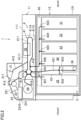
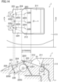
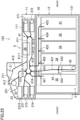
- FIG. 2 is a schematic view of an internal configuration of the banknote handling apparatus 1.
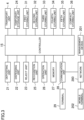
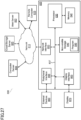
- FIG. 3 is a block diagram illustrating a configuration of the banknote handling apparatus 1.
- the banknote handling apparatus 1 handles loose notes.
- the banknote handling apparatus 1 includes an upper handling unit 11 and a lower safe unit 13.
- the handling unit 11 is comprised of an upper housing 111.
- a depositing unit 21, a dispensing unit 22, a reject unit 23, a temporary storage unit 24, a recognition unit 25, and an upper transport unit 41 are disposed in the upper housing 111.
- the upper transport unit 41 is a part of a transport unit 4.
- An operator can draw the upper housing 111, that is, a portion surrounded by a dot-dash line in FIG. 2 , out to the front. This drawable portion includes the depositing unit 21, the dispensing unit 22, the reject unit 23, the temporary storage unit 24, the recognition unit 25, and the upper transport unit 41.
- the safe unit 13 is comprised of a safe housing 131.
- a safe housing 131 In the safe housing 131, a plurality of storing units 31 to 35, a compact storing unit 36, a lower transport unit 42, and a second lower transport unit 43 are disposed.
- the lower transport unit 42 and the second lower transport unit 43 are a part of the transport unit 4.
- the safe housing 131 protects the storing units 31 to 35 and 36 at a security level equal to or higher than a predetermined level.
- the safe housing 131 is comprised of a metal board of a thickness equal to or higher than a predetermined thickness.
- the security level of the safe housing 131 is higher than that of the upper housing 111.
- the depositing unit 21 is a portion of the apparatus into which the banknotes to be deposited are inserted, for example, in a depositing process.
- the depositing unit 21 has an inlet 211.
- the inlet 211 opens upward at a front portion of the upper housing 111.
- the operator manually inserts the banknotes into the depositing unit 21 through the inlet 211.
- the depositing unit 21 is capable of holding a plurality of banknotes while the banknotes are stacked.
- the depositing unit 21 has a mechanism that takes the banknotes one by one into the banknote handling apparatus 1.
- the dispensing unit 22 is a portion of the apparatus to which banknotes fed from the storing unit are transported, for example, in a dispensing process.
- the dispensing unit 22 is capable of holding a plurality of banknotes while the banknotes are stacked.
- the dispensing unit 22 has an outlet 221.
- the outlet 221 opens upward at a position closer to the front than the inlet 211. The operator can manually remove the banknotes stacked in the dispensing unit 22 through the outlet 221.
- the outlet 221 may be provided with a shutter which opens and closes.
- the reject unit 23 is a portion of the apparatus to which banknotes rejected, for example, in a depositing process, are transported.
- the reject unit 23 is disposed in the front portion of the upper housing 111.
- the reject unit 23 is configured to hold a plurality of banknotes while the banknotes are stacked.
- the reject unit 23 has a second outlet 231.
- the second outlet 231 opens frontward at a front portion of the upper housing 111.
- the second outlet 231 is provided with a shutter 2310.
- the shutter 2310 is provided at a front surface of the upper housing 111, as shown in FIG. 1 . When the shutter 2310 opens, the operator can remove the banknotes stacked in the reject unit 23 through the second outlet 231.
- the recognition unit 25 is disposed in a first transport path 411 that will be described later.
- the recognition unit 23 is an imaging device, such as a camera or sensor.
- the recognition unit 25 recognizes at least whether each banknote being transported through the first transport path 411 is authentic or not, a denomination of each banknote, or whether each banknote is fit or unfit.
- the recognition unit 25 further acquires a serial number of each of the banknotes.
- the banknote handling apparatus 1 includes a first storing unit 31, a second storing unit 32, a third storing unit 33, a fourth storing unit 34, and a fifth storing unit 35.
- the first storing unit 31, the second storing unit 32, the third storing unit 33, the fourth storing unit 34, and the fifth storing unit 35 are aligned in the front-rear direction inside the safe housing 131.
- the storing units 31 to 35 and a compact storing unit 36, which will be described later, constitute a storage section 3.
- the first storing unit 31, the second storing unit 32, the third storing unit 33, and the fourth storing unit 34 store the banknotes of different denominations.
- the fifth storing unit 35 stores the banknotes that are not stored in the first storing unit 31, the second storing unit 32, the third storing unit 33, and the fourth storing unit 34.
- the fifth storing unit 35 may also store the banknotes to be collected from the banknote handling apparatus 1.
- the tenth transport path 422 connects the second lower transport unit 43 and the seventh transport path 417 with each other.
- the tenth transport path 422 transports the banknotes from the seventh transport path 417 toward the second lower transport unit 43 and from the second lower transport unit 43 toward the seventh transport path 417.
- the eleventh transport path 423 connects each of the first storing unit 31, the second storing unit 32, the third storing unit 33, and the fourth storing unit 34 with the eighth transport path 418.
- the eleventh transport path 423 transports banknotes from the eighth transport path 418 toward each of the storing units 31 to 34 and from each of the storing units 31 to 34 toward the eighth transport path 418. More specifically, the eleventh transport path 423 extends in the front-rear direction. An end of the eleventh transport path 423 is connected to the first storing unit 31.
- the eleventh transport path 423 includes three branches 424, 425, and 426.
- the branch 424 is connected to the second storing unit 32.
- the branch 425 is connected to the third storing unit 33.
- the branch 426 is connected to the fourth storing unit 34. Junctions of the branches 424, 425, and 426 are provided with diverters.
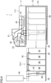
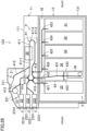
- FIG. 5 illustrates a banknote handling apparatus 101 according to a variation.
- configurations of a fourth storing unit 340 and a fifth storing unit 350 are different from those of the banknote handling apparatus 1 shown in FIG. 2 .
- the banknote handling apparatus 1 includes the controller 15.
- the depositing unit 21, the dispensing unit 22, the reject unit 23, the temporary storage unit 24, the recognition unit 25, the transport unit 4, the first storing unit 31, the second storing unit 32, the third storing unit 33, the fourth storing unit 34, the fifth storing unit 35, and the compact storing unit 36 are connected to the controller 15 so as to be capable of exchanging signals with the controller 15.
- the banknote handling apparatus 1 includes an operation unit 26 operated by an operator, a memory 27 for storing various data, and a communication unit 28 for establishing communication with a terminal 29.
- the operation unit 26, the memory 27, and the communication unit 28 are connected to the controller 15 so as to be capable of exchanging signals with the controller 15.
- the operation unit 26 includes occupation switches 261. As shown in FIG. 1 , the occupation switches 261 are provided on both right and left side portions of the upper housing 111 of the banknote handling apparatus 1.
- the occupation switch 261 is, for example, a touch switch.
- the operator e.g., a teller operates the terminal 29 to execute various processes performed by using the banknote handling apparatus 1.
- the banknote handling apparatus 1 stores banknotes in the storage units.
- the operator inserts the banknotes to be deposited into the depositing unit 21.
- the depositing unit 21 takes the banknotes one by one into the apparatus.
- the transport unit 4 transports the banknotes to the recognition unit 25.
- the recognition unit 25 recognizes the banknotes.
- the transport unit 4 transports the banknotes to the first storing unit 31, the second storing unit 32, the third storing unit 33, the fourth storing unit 34, the fifth storing unit 35, or the compact storing unit 36, in accordance with the recognition results of the recognition unit 25.
- the storing units 31 to 36 store the banknotes.
- the transport unit 4 transports the banknotes recognized by the recognition unit 25 as banknotes to be rejected to the reject unit 23.
- the timing sensor 4110 is provided to each of the upper path 4111 of the first transport path 411 and the lower path 4112 of the first transport path 411. More specifically, the first timing sensor 4110 is arranged approximately in the center portion of the upper path 4111 in the front-rear direction. The second timing sensor 4110 is arranged approximately in the center portion of the lower path 4112 in the front-rear direction. The timing sensors 4110 detect leading edges of the banknotes transported forward and backward along the upper path 4111 or the lower path 4112. The controller 15 determines the timing of moving the diverters provided in the upper transport unit 41, based on detection signals of the timing sensors 4110. Moving the diverters at an appropriate timing allows the banknotes being transported along the first transport path 411 to be transported to a predetermined destination.
- the timing sensors 4110 are comprised of optical sensors, specifically, reflective optical sensors.
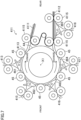
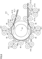
- the axis X1 extends in the right-left direction of the banknote handling apparatus 1.
- the driving roller 44 has a columnar or cylindrical shape with the axis X1 as a central axis. Approximately 3/4 of the outer peripheral surface of the driving roller 44 forms the transport path of the front curved portion 4113.
- the driven rollers 45 are disposed at intervals from each other along the outer peripheral surface of the driving roller 44. There are five driven rollers 45 in the example configuration of FIG. 7 . The five driven rollers 45 are disposed at even intervals from each other. Each of the driven rollers 45 abuts on the outer peripheral surface of the driving roller 44. Each of the driven rollers 45 has a diameter smaller than the diameter of the driving roller 44. Each of the driven rollers 45 is driven to rotate when the driving roller 44 rotates. Each of the driven rollers 45 has a rotational speed higher than the rotational speed of the driving roller 44.
- the driving roller 44 When the driving roller 44 rotates, the banknote interposed between the outer peripheral surface of the driving roller 44 and the driven rollers 45 is transported forward and backward.
- “forward” refers to the clockwise direction and "backward” refers to the counterclockwise direction.
- the driving roller 44 is an example of a second transport roller.
- the driving roller 44 rotates at a rotational speed of 441 rpm
- the driven roller 45 rotates at a rotational speed of 1910 rpm. Both rollers have a circumferential speed of 1600 mm/s.
- the diameter of the driving roller 44 is twice as long as the diameter of the driven roller 45, its rotational speed is half (1/2) of the rotational speed of the driven roller 45.
- the upper path 4111 of and the lower path 4112 of the first transport path 411 are provided with transport rollers 4115 for transporting the banknotes.
- a diameter of the transport roller 4115 is smaller than the diameter of the driving roller 44.
- the transport roller 4115 rotates at a rotational speed higher than the rotational speed of the driving roller 44.
- the banknote is transported at a constant speed.
- the controller 15 may change the rotational speed of the driving roller 44 and the rotational speed of the transport rollers 4115 based on the recognition results of the recognition unit 25. For example, if the recognition unit 25 recognizes an unfit note, the controller 15 may reduce the rotational speed of the driving roller 44 and the rotational speed of the transport roller 4115.
- the diverter 461 is provided at the connecting portion between the third transport path 413 and the front curved portion 4113.
- the diverter 462 is provided at the connecting portion between the fifth transport path 415 and the front curved portion 4113.
- the diverter 463 is provided at the connecting portion between the sixth transport path 416 and the front curved portion 4113.
- the diverter 464 is provided at the connecting portion between the seventh transport path 417 and the front curved portion 4113.
- Each of the diverters 461, 462, 463, and 464 are disposed between the driven rollers 45 that are adjacent in the circumferential direction.
- Each of the diverters 461 to 464 turns on an axis.
- the diverter 461 changes the transport direction of the banknote to three directions: a first forward direction from the front curved portion 4113 toward the third transport path 413; a second forward direction from the third transport path 413 toward the front curved portion 4113; and a third forward direction to transport the banknote along the front curved portion 4113.
- the diverter 461 changes the transport direction of the banknote to three directions: a first backward direction from the front curved portion 4113 toward the third transport path 413; a second backward direction from the third transport path 413 toward the front curved portion 4113; and a third backward direction to transport the banknote along the front curved portion 4113.
- the diverter 462 changes the transport direction of the banknote to three directions: a first forward direction from the front curved portion 4113 toward the fifth transport path 415; a second forward direction from the fifth transport path 415 toward the front curved portion 4113; and a third forward direction to transport the banknote along the front curved portion 4113.
- the diverter 462 changes the transport direction of the banknote to three directions: a first backward direction from the front curved portion 4113 toward the fifth transport path 415; a second backward direction from the fifth transport path 415 toward the front curved portion 4113; and a third backward direction to transport the banknote along the front curved portion 4113.
- the diverter 463 changes the transport direction of the banknote to three directions: a first forward direction from the front curved portion 4113 toward the sixth transport path 416; a second forward direction from the sixth transport path 416 toward the front curved portion 4113; and a third forward direction to transport the banknote along the front curved portion 4113.
- the diverter 463 changes the transport direction of the banknote to three directions: a first backward direction from the front curved portion 4113 toward the sixth transport path 416; a second backward direction from the sixth transport path 416 toward the front curved portion 4113; and a third backward direction to transport the banknote along the front curved portion 4113.
- the front curved portion 4113 configured as described above includes the driving roller 44.
- the driving roller 44 functions as both a roller and a guide of the curved portion having a known configuration.
- the front curved portion 4113 including the driving roller 44 has a smaller number of parts than that of a known configuration.
- the forward or reverse rotation of the driving roller 44 while the banknote is transported causes the inner peripheral portion of the front curved portion 4113 to rotate.
- jamming of banknotes is less likely to occur.
- Even if the front curved portion 4113 is provided with a plurality of three-way diverters 461 to 464, jamming of banknotes is less likely to occur in the front curved portion 4113 due to the rotation of the driving roller 44.
- the transportation of the banknote in the front curved portion 4113 is improved.
- timing sensors 4110 determining the driving timing of each of the diverters 461 to 464 of the front curved portion 4113 are disposed in the upper path 4111 and the lower path 4112. Since the timing sensors 4110 are not provided in the front curved portion 4113, the configuration of the front curved portion 4113 is simplified. The simplified configuration also contributes to reducing jamming of banknotes in the front curved portion 4113.
- the banknote Since the transportation of the banknote in the front curved portion 4113 is good, the banknote is stably transported to the dispensing unit 22 through the third transport path 413 or to the reject unit 23 through the fourth transport path 414.
- the banknote is stably transported to the temporary storage unit 24 through the fifth transport path 415 or to the fifth storing unit 35 through the sixth transport path 416.
- the banknote is stably transported to the second lower transport unit 43 through the seventh transport path 417.
- the banknote is stably transported to the upper storage 51 of the fifth storing unit 35 through the sixth transport path 416. Further, the banknote is stably transported through the seventh transport path 417 to the lower storage 52 of the fifth storing unit 35 or to the lower storage 52 of the fourth storing unit 34.
- Each of the diverters 461 to 465 transports the banknote to a predetermined destination by switching the transport direction of the banknote, based on the recognition results of the recognition unit 25.
- the transmissive optical sensor is a sensor that detects from a drop of the output voltage that a banknote has blocked an optical axis between the light emitter and the light receiver. With the paper powder and/or dust deposited on the light emitter and/or light receiver of the transmissive optical sensor, the output voltage in a state in which the banknote is not transported decreases.
- the transmissive optical sensor is capable of detecting the deposited amount of the paper powder and/or dust based on an output signal in a state in which the banknote is not transported.
- the first transport path 411 is provided with the transmissive optical sensor for detecting the deposited amount of paper powder and/or dust.
- the transmissive optical sensor 4116 is provided in the middle portion of the lower path 4112 in the front-rear direction. If paper powder and/or dust is deposited on the optical sensor 4116, it is assumed that paper powder and/or dust is deposited on other tracking sensors 419 and timing sensors 4110, as well.
- Step S2 the controller 15 determines whether the banknote handling apparatus 1 was reset. For example, if jamming of banknotes occurs, the banknote handling apparatus 1 is reset after the jam is removed. If the answer in Step S2 is YES, the process proceeds to Step S3. If the answer in Step S2 is NO, the process returns.
- Step S4 the controller 15 determines whether the deposited amount of paper powder and/or dust exceeds a predetermined value, based on the detection signal of the transmissive optical sensor 4116. Specifically, if the output voltage of the transmissive optical sensor 4116 in a state in which the banknote is not transported is equal to or lower than the predetermined value, the controller 15 may determine that the deposited amount exceeds the predetermined value because if the deposited amount of paper powder and/or dust increases, the amount of light that can be received in the light receiver of the transmissive optical sensor 4116, and hence the output voltage, decrease.
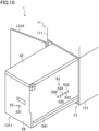
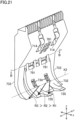
- FIG. 4 illustrates the banknote handling apparatus 1 with the fifth storing unit 31 taken out from the apparatus.
- the operator can also install the first to fifth storing units 31 to 35 in the banknote handling apparatus 1 and accommodate them in the safe housing 131.
- the operator may draw the first to fifth storing units 31 to 35 out of the safe housing 131 and take them out of the banknote handling apparatus 1 in the event, for example, that jamming of banknotes occurred in any one of the first to fifth storing units 31 to 35.
- the banknote handling apparatus 1 has a structure in which it is possible to install the first to fifth storing units 31 to 35 in positions other than the correct positions. In other words, it is possible to change positions of the first to fifth storing units 31 to 35 from one another in the safe housing 131.
- the first to fifth storing units 31 to 35 if installed at incorrect positions, may lead to inaccurate operation of the banknote handling apparatus 1.
- the first to fifth storing units 31 to 35 can be distinguished from each other based on, for example, the following points: (1) having a memory storing the serial number; (2) information, stored in the memory, about the denomination to be stored; (3) different attachments; and (4) a characteristic part attached.
- the controller 15 determines whether each of the storing units 31 to 35 is in the correct position, based on at least one of the points (1) to (4).
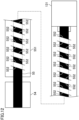
- the five LEDs 532 to 536 aligned in the front-rear direction correspond to the first to fifth storing units 31 to 35 aligned in the front-rear direction, respectively.
- the positions of the LEDs 532 to 536 in the front-rear direction correspond to the positions of the first to fifth storing units 31 to 35 in the front-rear direction.
- the LEDs 532 to 536 respectively indicate the installation states of the first to fifth storing units 31 to 35.
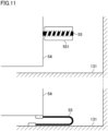
- the banknote handling apparatus 1 includes an occupation light 262.
- the occupation light 262 displays the state of occupation of the banknote handling apparatus 1.
- the occupation light 262 is provided at the front portion of the upper housing 111 of the banknote handling apparatus 1.
- the occupation light 262 is provided on each of both right and left side portions of the upper housing 111.
- the occupation light 262 extends from the upper side to the front side of the upper housing 111 and, as shown in FIG. 13 , has an inverted L-shape in a side view.
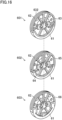
- FIG. 17 is an exploded view of the feed roller 601 of the first example configuration.
- FIGS. 16 and 17 are upside down to each other.
- the feed roller 601 is comprised of a rubber portion 61, a metal plate 62, and a resin portion 63.
- the metal plate 62 has approximately a C-shape.
- the resin portion 63 includes a hub 631, a rim 632, and a plurality of spokes 633.
- the spokes 633 connect the hub 631 and the rim 632.
- the hub 631 has a rotating shaft inserted therein.
- the rim 632 includes a groove 634 for the metal plate 62 to be inserted.
- a part of the outer peripheral surface of the rim 632 constitutes the outer peripheral surface of the feed roller 601. As shown in the upper drawing of FIG. 16 , this part is made of the resin rim 632 sandwiching the metal plate 62.
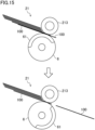
- the storing unit 7 includes a storing mechanism 700 and a frame 701 accommodating the storing mechanism 700.
- the storing mechanism 700 winds a banknote on a drum 73 together with tapes sandwiching the banknote therebetween.
- the banknote is wound onto the drum 73 such that the long edge of the banknote is parallel to the axis of the drum 73.
- the storing mechanism 700 includes a first reel 721, a second reel 722, and the drum 73.
- the movable guide 732 is biased in the counterclockwise direction in FIG. 20 by a biasing member (e.g., a spring).
- the movable guide 732 is biased in a direction bringing it closer to the drum 73.
- the movable guide 732 turns in the clockwise direction and in the counterclockwise direction, in accordance with the size of the diameter of the drum 73.
- the banknotes wound on the drum 73 are layered on each other in the radial direction of the drum 73. Since the layered banknotes are pressed to the drum 73 by the first tape 741 and the second tape 742, the diameter of the drum 73 is the smallest at the positions pressed by the first tape 741 and the second tape 742.
- the banknote is released from the restriction of the first tape 741 and the second tape 742 as it goes away from the positions where the banknote is pressed to the drum 73 by the first tape 741 and the second tape 742 toward the ends of the banknote in the direction of the axis X2 of the drum 73.
- the diameter of the drum 73 increases in size toward the axial ends of the axis X2.
- the banknote handling apparatus 1 is capable of executing various processes.
- the banknote handling apparatus 1 is shifted to the operation/standby mode 244 during the bank's working hours.
- the banknote handling apparatus 1 shifts to the sleep mode 242 when in the operation/standby mode 244 the operator long-presses the standby switch 82, or when in the operation/standby mode 244 a command to shift to the sleep mode is input from the management device 201, or when in the operation/standby mode 244 a command to shift to the sleep mode is input from the mobile terminal 202.
- the banknote handling apparatus 1 When the banknote handling apparatus 1 is in the eco mode 243, power is supplied to the controller 15, the memory 27, the communication unit 28, the operation unit 26, the recognition unit 25, and the storage section 3, as shown in the lower drawing in FIG. 24 . That is, power is supplied to the components other than driving portions in the banknote handling apparatus 1.
- This configuration achieves prompt shift from the eco mode 243 to the operation/standby mode 244. At the same time, it is possible to reduce the power consumption of the banknote handling apparatus 1.
- the banknote handling apparatus 1 shifts to the eco mode 243 when the banknote handling apparatus 1 is not used during the bank's working hours.
- the compact storing units 36, 371, 372, 373, and 374 are arranged in the upper housing 111 and in the safe housing 131. Using these compact storing units 36, 371, 372, 373, and 374 differently makes it possible that the banknote handling apparatus 102 executes various processes. This improves the usability of the banknote handling apparatus 102.
- a computer readable storage medium is not to be construed as being transitory signals per se, such as radio waves or other freely propagating electromagnetic waves, electromagnetic waves propagating through a waveguide or other transmission media (e.g., light pulses passing through a fiber-optic cable), or electrical signals transmitted through a wire.
- Computer readable program instructions described in this disclosure can be downloaded to an appropriate computing or processing device from a computer readable storage medium or to an external computer or external storage device via a global network (i.e., the Internet), a local area network, a wide area network and/or a wireless network.
- the network may include copper transmission wires, optical communication fibers, wireless transmission, routers, firewalls, switches, gateway computers and/or edge servers.
- a network adapter card or network interface in each computing or processing device may receive computer readable program instructions from the network and forward the computer readable program instructions for storage in a computer readable storage medium within the computing or processing device.
- Computer readable program instructions for carrying out operations of the present disclosure may include machine language instructions and/or microcode, which may be compiled or interpreted from source code written in any combination of one or more programming languages, including assembly language, Basic, Fortran, Java, Python, R, C, C++, C# or similar programming languages.
- the computer readable program instructions may execute entirely on a user's personal computer, notebook computer, tablet, or smartphone, entirely on a remote computer or computer server, or any combination of these computing devices.
- the remote computer or computer server may be connected to the user's device or devices through a computer network, including a local area network or a wide area network, or a global network (i.e., the Internet).
- the computer readable program instructions may also be loaded onto a computer, other programmable apparatus, or other device to cause a series of operational steps to be performed on the computer, other programmable apparatus or other device to produce a computer implemented process, such that the instructions which execute on the computer, other programmable apparatus, or other device implement the functions specified in the flow diagrams and block diagrams in the present disclosure.
- FIG. 27 is a functional block diagram illustrating a networked system 800 of one or more networked computers and servers, any one of which, or combinations of which may be the controller 15.
- the hardware and software environment illustrated in FIG. 27 may provide an exemplary platform for implementation of the software and/or methods according to the present disclosure.
- a networked system 800 may include, but is not limited to, computer 805, network 810, remote computer 815, web server 820, cloud storage server 825 and computer server 830. In some embodiments, multiple instances of one or more of the functional blocks illustrated in FIG. 27 may be employed.
- Computer 805 may be a personal computer (PC), a desktop computer, laptop computer, tablet computer, netbook computer, a personal digital assistant (PDA), a smart phone, or any other programmable electronic device capable of communicating with other devices on network 810.
- PC personal computer
- PDA personal digital assistant
- Computer 805 may include processor 835, bus 837, memory 840, non-volatile storage 845, network interface 850, peripheral interface 855 and display interface 865.
- processor 835 bus 837
- memory 840 non-volatile storage 845
- network interface 850 peripheral interface 855
- display interface 865 display interface 865.
- Processor 835 may be one or more single or multi-chip microprocessors, such as those designed and/or manufactured by Intel Corporation, Advanced Micro Devices, Inc. (AMD), Arm Holdings (Arm), Apple Computer, etc. Examples of microprocessors include Celeron, Pentium, Core i3, Core i5 and Core i7 from Intel Corporation; Opteron, Phenom, Athlon, Turion and Ryzen from AMD; and Cortex-A, Cortex-R and Cortex-M from Arm.
- Bus 837 may be a proprietary or industry standard high-speed parallel or serial peripheral interconnect bus, such as ISA, PCI, PCI Express (PCI-e), AGP, and the like.
- Memory 840 and non-volatile storage 845 may be computer-readable storage media.
- Non-volatile storage 845 may include one or more of the following: flexible disk, hard disk, solid-state drive (SSD), read-only memory (ROM), erasable programmable read-only memory (EPROM or Flash), compact disc (CD or CD-ROM), digital versatile disk (DVD) and memory card or stick.
- DRAM Dynamic Random Access Memory
- SRAM Static Random Access Memory
- Non-volatile storage 845 may include one or more of the following: flexible disk, hard disk, solid-state drive (SSD), read-only memory (ROM), erasable programmable read-only memory (EPROM or Flash), compact disc (CD or CD-ROM), digital versatile disk (DVD) and memory card or stick.
- Program 848 may be a collection of machine readable instructions and/or data that is stored in non-volatile storage 845 and is used to create, manage, and control certain software functions that are discussed in detail elsewhere in the present disclosure and illustrated in the drawings.
- memory 840 may be considerably faster than non-volatile storage 845.
- program 848 may be transferred from non-volatile storage 845 to memory 840 prior to execution by processor 835.
- Peripheral interface 855 may allow for input and output of data with other devices that may be connected locally with computer 805.
- peripheral interface 855 may provide a connection to external devices 860.
- External devices 860 may include devices such as a keyboard, a mouse, a keypad, a touch screen, and/or other suitable input devices.
- External devices 860 may also include portable computer-readable storage media such as, for example, thumb drives, portable optical or magnetic disks, and memory cards.
- Software and data used to practice embodiments of the present disclosure, for example, program 848, may be stored on such portable computer-readable storage media. In such embodiments, software may be loaded onto non-volatile storage 845 or, alternatively, directly into memory 840 via peripheral interface 855.
- Peripheral interface 855 may use an industry standard connection, such as RS-232 or Universal Serial Bus (USB), to connect with external devices 860.
- Display interface 865 may connect computer 805 to display 870.
- Display 870 may be used, in some embodiments, to present a command line or graphical user interface to a user of computer 805.
- Display interface 865 may connect to display 870 using one or more proprietary or industry standard connections, such as VGA, DVI, DisplayPort and HDMI.
- network interface 850 provides for communications with other computing and storage systems or devices external to computer 805.
- Software programs and data discussed herein may be downloaded from, for example, remote computer 815, web server 820, cloud storage server 825 and computer server 830 to non-volatile storage 845 through network interface 850 and network 810.
- the systems and methods described in this disclosure may be executed by one or more computers connected to computer 805 through network interface 850 and network 810.
- the systems and methods described in this disclosure may be executed by remote computer 815, computer server 830, or a combination of the interconnected computers on network 810.
- Data, datasets and/or databases employed in embodiments of the systems and methods described in this disclosure may be stored and or downloaded from remote computer 815, web server 820, cloud storage server 825 and computer server 830.
Landscapes
- Engineering & Computer Science (AREA)
- Mechanical Engineering (AREA)
- Physics & Mathematics (AREA)
- General Physics & Mathematics (AREA)
- Health & Medical Sciences (AREA)
- General Health & Medical Sciences (AREA)
- Toxicology (AREA)
- Separation, Sorting, Adjustment, Or Bending Of Sheets To Be Conveyed (AREA)
- Delivering By Means Of Belts And Rollers (AREA)
Claims (13)
- Vorrichtung zur Handhabung von Bögen (1, 101, 102, 103), umfassend:einen Transportpfad (411), der einen ersten Pfad (4111), einen zweiten Pfad (4112) und einen gekrümmten Abschnitt (4113), der den ersten Pfad (4111) und den zweiten Pfad (4112) verbindet, umfasst, wobei der Transportpfad (411) einen Bogen entlang des Transportpfads (411) in einer Vorwärtsrichtung oder einer Rückwärtsrichtung zirkulierend transportiert;einen Walzkörper (44, 47), der an dem gekrümmten Abschnitt (4113) angeordnet ist und sich im und gegen den Uhrzeigersinn dreht; undeine Vielzahl von Walzen (45), die dem Walzkörper (44, 47) gegenüberliegen und den Bogen zwischen den Walzen der Vielzahl von Walzen (45) und dem Walzkörper (44, 47) entlang des gekrümmten Abschnitts (4113) des Transportwegs (411) einklemmen, wobeider Rollkörper (44, 47) transportiert das Blech in Vorwärtsrichtung durch Drehung im Uhrzeigersinn und transportiert das Blech in Rückwärtsrichtung durch Drehung gegen den Uhrzeigersinn,die Vorrichtung zur Handhabung von Bögen (1, 101, 102, 103) ferner umfasst:mindestens einen ersten Zweig (413, 415, 416, 417), der mit dem gekrümmten Abschnitt (4113) verbunden ist; undeine Umlenkeinrichtung (461, 462, 463, 464), die eine Transportrichtung des Bogens ändert, wobei die Umlenkeinrichtung (461, 462, 463, 464) an einer ersten Verbindungsstelle vorgesehen ist, an der der erste Zweig (413, 415, 416, 417) angeschlossen ist, und die Vorrichtung dadurch gekennzeichnet ist, dasswenn der Bogen in Vorwärtsrichtung entlang des Transportweges (411) transportiert wird, ändert die Umlenkeinrichtung (461, 462, 463, 464) die Transportrichtung des Bogens in eine von drei Richtungen, einschließlich:eine erste Vorwärtsrichtung, in der der Bogen vom Transportweg (411) in Richtung der ersten Verzweigung (413, 415, 416, 417) transportiert wird;eine zweite Vorwärtsrichtung, in der der Bogen von der ersten Verzweigung (413, 415, 416, 417) zum Transportweg (411) transportiert wird; undeine dritte Vorwärtsrichtung, in der der Bogen entlang des Transportwegs (411) transportiert wird.
- Vorrichtung zur Handhabung von Bögen (1, 101, 102, 103) nach Anspruch 1, bei der, wenn der Bogen in Rückwärtsrichtung entlang des Transportwegs (411) transportiert wird, die Umlenkeinrichtung (461, 462, 463, 464) die Transportrichtung des Bogens in eine von drei Richtungen ändert, einschließlich:eine erste Rückwärtsrichtung, in der der Bogen vom Transportweg (411) in Richtung der ersten Verzweigung (413, 415, 416, 417) transportiert wird;eine zweite Rückwärtsrichtung, in der der Bogen von der ersten Verzweigung (413, 415, 416, 417) zum Transportweg (411) transportiert wird; undeine dritte Rückwärtsrichtung, in der der Bogen entlang des Transportweges (411) transportiert wird.
- Vorrichtung zur Handhabung von Bögen (1, 101, 102, 103) nach Anspruch 1 oder 2, bei der die erste Abzweigung (416, 417) mit einem ersten Speicher (35, 36, 340, 350) zum Speichern des Bogens verbunden ist.
- Vorrichtung zur Handhabung von Bögen (1, 101, 102, 103) nach Anspruch 3, bei derder erste Speicher (340, 350) ist in einen oberen Speicher (51) und einen unteren Speicher (52) unterteilt, undder erste Zweig (416, 417) mindestens einen zweiten mit dem oberen Speicher (51) verbundenen Zweig oder einen dritten mit dem unteren Speicher (52) verbundenen Zweig umfasst.
- Vorrichtung zur Handhabung von Bögen (1, 101, 102, 103) nach Anspruch 1 oder 2, bei der die erste Verzweigung mindestens eines der folgenden Elemente umfasst:einen zweiten Zweig (415), der mit einem Zwischenspeicher verbunden ist, der den Bogen aufnimmt, so dass der Bogen gespeichert und zugeführt wird,eine dritte Abzweigung (413), die mit einem Spender verbunden ist, der den Bogen an die Außenseite der Vorrichtung zur Handhabung von Bögen abgibt, odereine vierte Abzweigung (416), die mit einem oberen Speicher für die Speicherung des Bogens verbunden ist.
- Vorrichtung zur Handhabung von Bögen (1, 101, 102, 103) nach einem der Ansprüche 1 bis 5, bei dermindestens ein zweiter Zweig (418) mit dem zweiten Pfad (4112) verbunden ist, unddie Abzweigung (465) ist an einer zweiten Verzweigung vorgesehen, an der der zweite Zweig (418) angeschlossen ist.
- Vorrichtung zur Handhabung von Bögen (1, 101, 102, 103) nach Anspruch 6, bei der die zweite Abzweigung (418) mit einem zweiten Speicher (31, 32, 33, 34, 340) zum Speichern des Bogens verbunden ist.
- Vorrichtung zur Handhabung von Bögen (1, 101, 102, 103) nach einem der Ansprüche 1 bis 7, die ferner umfasst:einen Erkennungssensor (25), der am ersten Pfad (411) angeordnet ist und der Bogen erkennt, wobeidie Umlenkung (461, 462, 463, 464) die Transportrichtung des Bogens auf der Grundlage eines Erkennungsergebnisses des Erkennungssensors (25) ändert.
- Vorrichtung zur Handhabung von Bögen (1, 101, 102, 103) nach Anspruch 8, bei derder erste Weg (4111) und der zweite Weg (4112) eine erste Transportrolle (4115) zum Transportieren des Bogens enthalten, unddie erste Transportrolle (4115) einen Durchmesser hat, der kleiner ist als ein Durchmesser des Rollkörpers (44, 47).
- Vorrichtung zur Handhabung von Bögen (1, 101, 102, 103) nach einem der Ansprüche 1 bis 9, die ferner umfasst:einen Sensor (419, 4110), der am Transportweg (411) angeordnet ist und den Bogen erfasst, undeine Verarbeitungsschaltung (15), die die Umlenkeinrichtung (461, 462, 463, 464) auf der Grundlage eines Erfassungsergebnisses des Sensors (419, 4110) steuert.
- Vorrichtung zur Handhabung von Bögen (1, 101, 102, 103) nach einem der Ansprüche 1 bis 10, bei der der Walzkörper eine Transportwalze (44) ist, die den Bogen transportiert, wenn der Bogen zwischen einer Umfangsfläche des Walzkörpers und Walzen der Vielzahl von Walzen eingeschlossen ist.
- Vorrichtung zur Handhabung von Bögen (1, 101, 102, 103) nach einem der Ansprüche 1 bis 10, bei derder Walzkörper ist eine Riemenscheibe (47) mit einer Umfangsfläche, auf die ein Riemen (48) gewickelt ist, undder Bogen transportiert wird, während er zwischen dem Band (48) und den Rollen (45) der Vielzahl von Rollen (45) eingeklemmt ist.
- Vorrichtung zur Handhabung von Bögen (1, 101, 102, 103) nach einem der Ansprüche 1 bis 12, ferner umfassend
Verarbeitungsschaltungen, die so konfiguriert sind, dass sie den Rollkörper so steuern, dass er sich im oder gegen den Uhrzeigersinn dreht.
Applications Claiming Priority (1)
| Application Number | Priority Date | Filing Date | Title |
|---|---|---|---|
| JP2019237612A JP2021105894A (ja) | 2019-12-27 | 2019-12-27 | 紙葉類処理装置 |
Publications (2)
| Publication Number | Publication Date |
|---|---|
| EP3842368A1 EP3842368A1 (de) | 2021-06-30 |
| EP3842368B1 true EP3842368B1 (de) | 2024-07-03 |
Family
ID=73856819
Family Applications (1)
| Application Number | Title | Priority Date | Filing Date |
|---|---|---|---|
| EP20216499.2A Active EP3842368B1 (de) | 2019-12-27 | 2020-12-22 | Vorrichtung zur blatthandhabung |
Country Status (3)
| Country | Link |
|---|---|
| US (1) | US20210201616A1 (de) |
| EP (1) | EP3842368B1 (de) |
| JP (1) | JP2021105894A (de) |
Families Citing this family (2)
| Publication number | Priority date | Publication date | Assignee | Title |
|---|---|---|---|---|
| JP2022141119A (ja) * | 2021-03-15 | 2022-09-29 | グローリー株式会社 | 貨幣処理装置 |
| US20230401920A1 (en) * | 2022-06-13 | 2023-12-14 | Ncr Corporation | Compact reject bin |
Family Cites Families (23)
| Publication number | Priority date | Publication date | Assignee | Title |
|---|---|---|---|---|
| GB2280893A (en) * | 1993-08-11 | 1995-02-15 | Inter Innovation Ab | Sheet circulation module |
| US8297427B2 (en) * | 2005-03-29 | 2012-10-30 | Glory Ltd. | Banknote handling apparatus |
| JP5172257B2 (ja) * | 2007-09-12 | 2013-03-27 | グローリー株式会社 | 紙葉類分岐機構、紙葉類処理装置および紙葉類分岐方法 |
| JP2009249174A (ja) * | 2008-04-10 | 2009-10-29 | Oki Electric Ind Co Ltd | 紙葉類搬送切替え装置 |
| US7886965B2 (en) * | 2008-05-16 | 2011-02-15 | Ncr Corporation | Scaleable check processing module for a self-service check depositing terminal |
| JP5463748B2 (ja) * | 2009-06-16 | 2014-04-09 | 沖電気工業株式会社 | 媒体処理装置 |
| US9189909B2 (en) * | 2009-09-25 | 2015-11-17 | Glory Ltd. | Banknote handling apparatus |
| US9171416B2 (en) * | 2010-01-29 | 2015-10-27 | Glory Ltd. | Banknote handling apparatus and banknote handling method |
| US8424755B1 (en) * | 2010-09-02 | 2013-04-23 | Diebold Self-Service Systems Division Of Diebold, Incorporated | Banking apparatus operated responsive to data bearing records |
| JP5877518B2 (ja) * | 2010-12-08 | 2016-03-08 | 沖電気工業株式会社 | 紙幣搬送機構および紙幣入出金装置 |
| JP2012165836A (ja) * | 2011-02-10 | 2012-09-06 | Glory Ltd | 紙幣搬送システム |
| KR101581725B1 (ko) * | 2011-07-21 | 2016-01-21 | 노틸러스효성 주식회사 | 현금 및 수표 번들 입금기 |
| KR101258809B1 (ko) * | 2011-07-25 | 2013-04-26 | 노틸러스효성 주식회사 | 금융 자동화기기 및 그의 매체 정렬 방법 |
| JP5790450B2 (ja) * | 2011-11-30 | 2015-10-07 | 沖電気工業株式会社 | 紙幣処理装置 |
| JP6438642B2 (ja) * | 2012-12-20 | 2018-12-19 | 沖電気工業株式会社 | 紙葉類取扱装置 |
| JP6252056B2 (ja) * | 2013-09-13 | 2017-12-27 | 沖電気工業株式会社 | 紙幣入出金装置及び紙幣取引装置 |
| JP6206108B2 (ja) * | 2013-11-14 | 2017-10-04 | 沖電気工業株式会社 | 紙幣処理装置 |
| JP2016099677A (ja) * | 2014-11-18 | 2016-05-30 | グローリー株式会社 | 紙幣処理装置 |
| JP6380039B2 (ja) * | 2014-11-20 | 2018-08-29 | 沖電気工業株式会社 | 搬送路切替装置及び媒体取引装置 |
| JP2017027198A (ja) * | 2015-07-17 | 2017-02-02 | ローレルバンクマシン株式会社 | 紙葉類処理装置 |
| JP2017084036A (ja) * | 2015-10-27 | 2017-05-18 | ローレル精機株式会社 | 紙葉類処理装置及び仕切りカード |
| US10766727B2 (en) * | 2015-11-18 | 2020-09-08 | Glory Ltd. | Paper sheet processing device and paper sheet processing method |
| JP7035563B2 (ja) * | 2018-01-26 | 2022-03-15 | 沖電気工業株式会社 | 媒体処理装置及び自動取引装置 |
-
2019
- 2019-12-27 JP JP2019237612A patent/JP2021105894A/ja active Pending
-
2020
- 2020-12-22 EP EP20216499.2A patent/EP3842368B1/de active Active
- 2020-12-23 US US17/131,836 patent/US20210201616A1/en not_active Abandoned
Also Published As
| Publication number | Publication date |
|---|---|
| EP3842368A1 (de) | 2021-06-30 |
| US20210201616A1 (en) | 2021-07-01 |
| JP2021105894A (ja) | 2021-07-26 |
Similar Documents
| Publication | Publication Date | Title |
|---|---|---|
| AU2002328716B2 (en) | Banknote accumulator | |
| JP5704027B2 (ja) | 媒体処理装置及び媒体取引装置 | |
| US9546066B2 (en) | Medium storage and feed-out device and medium transaction apparatus | |
| AU2002328716A1 (en) | Banknote accumulator | |
| CN207601905U (zh) | 纸币收纳装置及纸币处理机 | |
| US9604812B2 (en) | Medium processing apparatus | |
| WO2011077876A1 (ja) | 自動取引装置 | |
| JP5976497B2 (ja) | 紙幣処理装置及び紙幣処理装置の制御方法 | |
| EP3842368B1 (de) | Vorrichtung zur blatthandhabung | |
| CN104282075B (zh) | 纸币处理装置 | |
| JP5935512B2 (ja) | 媒体処理装置及び媒体取引装置 | |
| JP2016081289A (ja) | 搬送方向切替装置、紙葉類取扱装置及び自動取引装置 | |
| CN104854629A (zh) | 介质处理装置和介质交易装置 | |
| KR101041205B1 (ko) | 반송 방향 전환 장치 및 지엽류 반송 장치 | |
| US20180257884A1 (en) | Paper sheet storing/feeding device | |
| EP3211608B1 (de) | Papierbogenverarbeitungsvorrichtung, papierbogenverarbeitungssystem und papierbogenverarbeitungsverfahren | |
| US12230090B2 (en) | Sheet storage device | |
| US11851299B2 (en) | Sheet storage device | |
| CN104812687B (zh) | 介质收纳送出装置及介质处理装置 | |
| JP5500267B2 (ja) | 自動取引装置 | |
| RU2749332C1 (ru) | Устройство обработки средств обращения и устройство транзакции средств обращения | |
| JP2018184289A (ja) | 媒体処理装置及び自動取引装置 | |
| JP6823450B2 (ja) | 紙幣識別収納装置 | |
| CN106204954A (zh) | 动力传递机构 | |
| JP2016157251A (ja) | 媒体収納庫及び媒体処理装置 |
Legal Events
| Date | Code | Title | Description |
|---|---|---|---|
| PUAI | Public reference made under article 153(3) epc to a published international application that has entered the european phase |
Free format text: ORIGINAL CODE: 0009012 |
|
| STAA | Information on the status of an ep patent application or granted ep patent |
Free format text: STATUS: REQUEST FOR EXAMINATION WAS MADE |
|
| 17P | Request for examination filed |
Effective date: 20201222 |
|
| AK | Designated contracting states |
Kind code of ref document: A1 Designated state(s): AL AT BE BG CH CY CZ DE DK EE ES FI FR GB GR HR HU IE IS IT LI LT LU LV MC MK MT NL NO PL PT RO RS SE SI SK SM TR |
|
| P01 | Opt-out of the competence of the unified patent court (upc) registered |
Effective date: 20230531 |
|
| STAA | Information on the status of an ep patent application or granted ep patent |
Free format text: STATUS: EXAMINATION IS IN PROGRESS |
|
| 17Q | First examination report despatched |
Effective date: 20231107 |
|
| GRAP | Despatch of communication of intention to grant a patent |
Free format text: ORIGINAL CODE: EPIDOSNIGR1 |
|
| STAA | Information on the status of an ep patent application or granted ep patent |
Free format text: STATUS: GRANT OF PATENT IS INTENDED |
|
| RIC1 | Information provided on ipc code assigned before grant |
Ipc: B65H 31/02 20060101ALI20240118BHEP Ipc: B65H 29/00 20060101ALI20240118BHEP Ipc: B65H 43/08 20060101ALI20240118BHEP Ipc: B65H 43/02 20060101ALI20240118BHEP Ipc: B65H 31/24 20060101ALI20240118BHEP Ipc: B65H 31/22 20060101ALI20240118BHEP Ipc: B65H 29/58 20060101ALI20240118BHEP Ipc: B65H 29/52 20060101ALI20240118BHEP Ipc: B65H 3/06 20060101ALI20240118BHEP Ipc: B65H 1/06 20060101ALI20240118BHEP Ipc: B65H 29/60 20060101ALI20240118BHEP Ipc: B65H 5/26 20060101ALI20240118BHEP Ipc: B65H 5/06 20060101AFI20240118BHEP |
|
| INTG | Intention to grant announced |
Effective date: 20240205 |
|
| GRAS | Grant fee paid |
Free format text: ORIGINAL CODE: EPIDOSNIGR3 |
|
| GRAA | (expected) grant |
Free format text: ORIGINAL CODE: 0009210 |
|
| STAA | Information on the status of an ep patent application or granted ep patent |
Free format text: STATUS: THE PATENT HAS BEEN GRANTED |
|
| AK | Designated contracting states |
Kind code of ref document: B1 Designated state(s): AL AT BE BG CH CY CZ DE DK EE ES FI FR GB GR HR HU IE IS IT LI LT LU LV MC MK MT NL NO PL PT RO RS SE SI SK SM TR |
|
| REG | Reference to a national code |
Ref country code: CH Ref legal event code: EP |
|
| REG | Reference to a national code |
Ref country code: DE Ref legal event code: R096 Ref document number: 602020033256 Country of ref document: DE |
|
| REG | Reference to a national code |
Ref country code: LT Ref legal event code: MG9D |
|
| REG | Reference to a national code |
Ref country code: NL Ref legal event code: MP Effective date: 20240703 |
|
| PG25 | Lapsed in a contracting state [announced via postgrant information from national office to epo] |
Ref country code: PT Free format text: LAPSE BECAUSE OF FAILURE TO SUBMIT A TRANSLATION OF THE DESCRIPTION OR TO PAY THE FEE WITHIN THE PRESCRIBED TIME-LIMIT Effective date: 20241104 |
|
| REG | Reference to a national code |
Ref country code: AT Ref legal event code: MK05 Ref document number: 1699638 Country of ref document: AT Kind code of ref document: T Effective date: 20240703 |
|
| PG25 | Lapsed in a contracting state [announced via postgrant information from national office to epo] |
Ref country code: NL Free format text: LAPSE BECAUSE OF FAILURE TO SUBMIT A TRANSLATION OF THE DESCRIPTION OR TO PAY THE FEE WITHIN THE PRESCRIBED TIME-LIMIT Effective date: 20240703 |
|
| PG25 | Lapsed in a contracting state [announced via postgrant information from national office to epo] |
Ref country code: PT Free format text: LAPSE BECAUSE OF FAILURE TO SUBMIT A TRANSLATION OF THE DESCRIPTION OR TO PAY THE FEE WITHIN THE PRESCRIBED TIME-LIMIT Effective date: 20241104 Ref country code: NL Free format text: LAPSE BECAUSE OF FAILURE TO SUBMIT A TRANSLATION OF THE DESCRIPTION OR TO PAY THE FEE WITHIN THE PRESCRIBED TIME-LIMIT Effective date: 20240703 |
|
| PG25 | Lapsed in a contracting state [announced via postgrant information from national office to epo] |
Ref country code: NO Free format text: LAPSE BECAUSE OF FAILURE TO SUBMIT A TRANSLATION OF THE DESCRIPTION OR TO PAY THE FEE WITHIN THE PRESCRIBED TIME-LIMIT Effective date: 20241003 |
|
| PG25 | Lapsed in a contracting state [announced via postgrant information from national office to epo] |
Ref country code: FI Free format text: LAPSE BECAUSE OF FAILURE TO SUBMIT A TRANSLATION OF THE DESCRIPTION OR TO PAY THE FEE WITHIN THE PRESCRIBED TIME-LIMIT Effective date: 20240703 Ref country code: GR Free format text: LAPSE BECAUSE OF FAILURE TO SUBMIT A TRANSLATION OF THE DESCRIPTION OR TO PAY THE FEE WITHIN THE PRESCRIBED TIME-LIMIT Effective date: 20241004 Ref country code: PL Free format text: LAPSE BECAUSE OF FAILURE TO SUBMIT A TRANSLATION OF THE DESCRIPTION OR TO PAY THE FEE WITHIN THE PRESCRIBED TIME-LIMIT Effective date: 20240703 |
|
| PG25 | Lapsed in a contracting state [announced via postgrant information from national office to epo] |
Ref country code: BG Free format text: LAPSE BECAUSE OF FAILURE TO SUBMIT A TRANSLATION OF THE DESCRIPTION OR TO PAY THE FEE WITHIN THE PRESCRIBED TIME-LIMIT Effective date: 20240703 |
|
| PG25 | Lapsed in a contracting state [announced via postgrant information from national office to epo] |
Ref country code: LV Free format text: LAPSE BECAUSE OF FAILURE TO SUBMIT A TRANSLATION OF THE DESCRIPTION OR TO PAY THE FEE WITHIN THE PRESCRIBED TIME-LIMIT Effective date: 20240703 |
|
| PG25 | Lapsed in a contracting state [announced via postgrant information from national office to epo] |
Ref country code: AT Free format text: LAPSE BECAUSE OF FAILURE TO SUBMIT A TRANSLATION OF THE DESCRIPTION OR TO PAY THE FEE WITHIN THE PRESCRIBED TIME-LIMIT Effective date: 20240703 Ref country code: IS Free format text: LAPSE BECAUSE OF FAILURE TO SUBMIT A TRANSLATION OF THE DESCRIPTION OR TO PAY THE FEE WITHIN THE PRESCRIBED TIME-LIMIT Effective date: 20241103 |
|
| PG25 | Lapsed in a contracting state [announced via postgrant information from national office to epo] |
Ref country code: CZ Free format text: LAPSE BECAUSE OF FAILURE TO SUBMIT A TRANSLATION OF THE DESCRIPTION OR TO PAY THE FEE WITHIN THE PRESCRIBED TIME-LIMIT Effective date: 20240703 Ref country code: HR Free format text: LAPSE BECAUSE OF FAILURE TO SUBMIT A TRANSLATION OF THE DESCRIPTION OR TO PAY THE FEE WITHIN THE PRESCRIBED TIME-LIMIT Effective date: 20240703 |
|
| PG25 | Lapsed in a contracting state [announced via postgrant information from national office to epo] |
Ref country code: ES Free format text: LAPSE BECAUSE OF FAILURE TO SUBMIT A TRANSLATION OF THE DESCRIPTION OR TO PAY THE FEE WITHIN THE PRESCRIBED TIME-LIMIT Effective date: 20240703 Ref country code: RS Free format text: LAPSE BECAUSE OF FAILURE TO SUBMIT A TRANSLATION OF THE DESCRIPTION OR TO PAY THE FEE WITHIN THE PRESCRIBED TIME-LIMIT Effective date: 20241003 |
|
| PG25 | Lapsed in a contracting state [announced via postgrant information from national office to epo] |
Ref country code: RS Free format text: LAPSE BECAUSE OF FAILURE TO SUBMIT A TRANSLATION OF THE DESCRIPTION OR TO PAY THE FEE WITHIN THE PRESCRIBED TIME-LIMIT Effective date: 20241003 Ref country code: PL Free format text: LAPSE BECAUSE OF FAILURE TO SUBMIT A TRANSLATION OF THE DESCRIPTION OR TO PAY THE FEE WITHIN THE PRESCRIBED TIME-LIMIT Effective date: 20240703 Ref country code: NO Free format text: LAPSE BECAUSE OF FAILURE TO SUBMIT A TRANSLATION OF THE DESCRIPTION OR TO PAY THE FEE WITHIN THE PRESCRIBED TIME-LIMIT Effective date: 20241003 Ref country code: LV Free format text: LAPSE BECAUSE OF FAILURE TO SUBMIT A TRANSLATION OF THE DESCRIPTION OR TO PAY THE FEE WITHIN THE PRESCRIBED TIME-LIMIT Effective date: 20240703 Ref country code: IS Free format text: LAPSE BECAUSE OF FAILURE TO SUBMIT A TRANSLATION OF THE DESCRIPTION OR TO PAY THE FEE WITHIN THE PRESCRIBED TIME-LIMIT Effective date: 20241103 Ref country code: HR Free format text: LAPSE BECAUSE OF FAILURE TO SUBMIT A TRANSLATION OF THE DESCRIPTION OR TO PAY THE FEE WITHIN THE PRESCRIBED TIME-LIMIT Effective date: 20240703 Ref country code: GR Free format text: LAPSE BECAUSE OF FAILURE TO SUBMIT A TRANSLATION OF THE DESCRIPTION OR TO PAY THE FEE WITHIN THE PRESCRIBED TIME-LIMIT Effective date: 20241004 Ref country code: FI Free format text: LAPSE BECAUSE OF FAILURE TO SUBMIT A TRANSLATION OF THE DESCRIPTION OR TO PAY THE FEE WITHIN THE PRESCRIBED TIME-LIMIT Effective date: 20240703 Ref country code: ES Free format text: LAPSE BECAUSE OF FAILURE TO SUBMIT A TRANSLATION OF THE DESCRIPTION OR TO PAY THE FEE WITHIN THE PRESCRIBED TIME-LIMIT Effective date: 20240703 Ref country code: CZ Free format text: LAPSE BECAUSE OF FAILURE TO SUBMIT A TRANSLATION OF THE DESCRIPTION OR TO PAY THE FEE WITHIN THE PRESCRIBED TIME-LIMIT Effective date: 20240703 Ref country code: BG Free format text: LAPSE BECAUSE OF FAILURE TO SUBMIT A TRANSLATION OF THE DESCRIPTION OR TO PAY THE FEE WITHIN THE PRESCRIBED TIME-LIMIT Effective date: 20240703 Ref country code: AT Free format text: LAPSE BECAUSE OF FAILURE TO SUBMIT A TRANSLATION OF THE DESCRIPTION OR TO PAY THE FEE WITHIN THE PRESCRIBED TIME-LIMIT Effective date: 20240703 |
|
| REG | Reference to a national code |
Ref country code: DE Ref legal event code: R097 Ref document number: 602020033256 Country of ref document: DE |
|
| PG25 | Lapsed in a contracting state [announced via postgrant information from national office to epo] |
Ref country code: DK Free format text: LAPSE BECAUSE OF FAILURE TO SUBMIT A TRANSLATION OF THE DESCRIPTION OR TO PAY THE FEE WITHIN THE PRESCRIBED TIME-LIMIT Effective date: 20240703 Ref country code: SM Free format text: LAPSE BECAUSE OF FAILURE TO SUBMIT A TRANSLATION OF THE DESCRIPTION OR TO PAY THE FEE WITHIN THE PRESCRIBED TIME-LIMIT Effective date: 20240703 Ref country code: RO Free format text: LAPSE BECAUSE OF FAILURE TO SUBMIT A TRANSLATION OF THE DESCRIPTION OR TO PAY THE FEE WITHIN THE PRESCRIBED TIME-LIMIT Effective date: 20240703 |
|
| PG25 | Lapsed in a contracting state [announced via postgrant information from national office to epo] |
Ref country code: EE Free format text: LAPSE BECAUSE OF FAILURE TO SUBMIT A TRANSLATION OF THE DESCRIPTION OR TO PAY THE FEE WITHIN THE PRESCRIBED TIME-LIMIT Effective date: 20240703 |
|
| PG25 | Lapsed in a contracting state [announced via postgrant information from national office to epo] |
Ref country code: SK Free format text: LAPSE BECAUSE OF FAILURE TO SUBMIT A TRANSLATION OF THE DESCRIPTION OR TO PAY THE FEE WITHIN THE PRESCRIBED TIME-LIMIT Effective date: 20240703 |
|
| PLBE | No opposition filed within time limit |
Free format text: ORIGINAL CODE: 0009261 |
|
| STAA | Information on the status of an ep patent application or granted ep patent |
Free format text: STATUS: NO OPPOSITION FILED WITHIN TIME LIMIT |
|
| 26N | No opposition filed |
Effective date: 20250404 |
|
| PG25 | Lapsed in a contracting state [announced via postgrant information from national office to epo] |
Ref country code: MC Free format text: LAPSE BECAUSE OF FAILURE TO SUBMIT A TRANSLATION OF THE DESCRIPTION OR TO PAY THE FEE WITHIN THE PRESCRIBED TIME-LIMIT Effective date: 20240703 |
|
| REG | Reference to a national code |
Ref country code: CH Ref legal event code: PL |
|
| PG25 | Lapsed in a contracting state [announced via postgrant information from national office to epo] |
Ref country code: LU Free format text: LAPSE BECAUSE OF NON-PAYMENT OF DUE FEES Effective date: 20241222 |
|
| PG25 | Lapsed in a contracting state [announced via postgrant information from national office to epo] |
Ref country code: SE Free format text: LAPSE BECAUSE OF FAILURE TO SUBMIT A TRANSLATION OF THE DESCRIPTION OR TO PAY THE FEE WITHIN THE PRESCRIBED TIME-LIMIT Effective date: 20240703 |
|
| REG | Reference to a national code |
Ref country code: BE Ref legal event code: MM Effective date: 20241231 |
|
| PG25 | Lapsed in a contracting state [announced via postgrant information from national office to epo] |
Ref country code: BE Free format text: LAPSE BECAUSE OF NON-PAYMENT OF DUE FEES Effective date: 20241231 |
|
| PG25 | Lapsed in a contracting state [announced via postgrant information from national office to epo] |
Ref country code: CH Free format text: LAPSE BECAUSE OF NON-PAYMENT OF DUE FEES Effective date: 20241231 |
|
| PG25 | Lapsed in a contracting state [announced via postgrant information from national office to epo] |
Ref country code: IE Free format text: LAPSE BECAUSE OF NON-PAYMENT OF DUE FEES Effective date: 20241222 |
|
| PGFP | Annual fee paid to national office [announced via postgrant information from national office to epo] |
Ref country code: DE Payment date: 20251211 Year of fee payment: 6 |
|
| PGFP | Annual fee paid to national office [announced via postgrant information from national office to epo] |
Ref country code: GB Payment date: 20251219 Year of fee payment: 6 |
|
| PGFP | Annual fee paid to national office [announced via postgrant information from national office to epo] |
Ref country code: IT Payment date: 20251223 Year of fee payment: 6 |
|
| PGFP | Annual fee paid to national office [announced via postgrant information from national office to epo] |
Ref country code: FR Payment date: 20251229 Year of fee payment: 6 |