EP3840109B1 - Batteriemodul mit pfad, durch den bei thermischem durchgehen das innen zugeführte kühlmittel fliessen kann, und batteriesatz und ess damit - Google Patents
Batteriemodul mit pfad, durch den bei thermischem durchgehen das innen zugeführte kühlmittel fliessen kann, und batteriesatz und ess damit Download PDFInfo
- Publication number
- EP3840109B1 EP3840109B1 EP20815309.8A EP20815309A EP3840109B1 EP 3840109 B1 EP3840109 B1 EP 3840109B1 EP 20815309 A EP20815309 A EP 20815309A EP 3840109 B1 EP3840109 B1 EP 3840109B1
- Authority
- EP
- European Patent Office
- Prior art keywords
- module
- battery
- air
- battery module
- coolant
- Prior art date
- Legal status (The legal status is an assumption and is not a legal conclusion. Google has not performed a legal analysis and makes no representation as to the accuracy of the status listed.)
- Active
Links
Images

Classifications
-
- H—ELECTRICITY
- H01—ELECTRIC ELEMENTS
- H01M—PROCESSES OR MEANS, e.g. BATTERIES, FOR THE DIRECT CONVERSION OF CHEMICAL ENERGY INTO ELECTRICAL ENERGY
- H01M50/00—Constructional details or processes of manufacture of the non-active parts of electrochemical cells other than fuel cells, e.g. hybrid cells
- H01M50/20—Mountings; Secondary casings or frames; Racks, modules or packs; Suspension devices; Shock absorbers; Transport or carrying devices; Holders
- H01M50/204—Racks, modules or packs for multiple batteries or multiple cells
- H01M50/207—Racks, modules or packs for multiple batteries or multiple cells characterised by their shape
- H01M50/209—Racks, modules or packs for multiple batteries or multiple cells characterised by their shape adapted for prismatic or rectangular cells
-
- H—ELECTRICITY
- H01—ELECTRIC ELEMENTS
- H01M—PROCESSES OR MEANS, e.g. BATTERIES, FOR THE DIRECT CONVERSION OF CHEMICAL ENERGY INTO ELECTRICAL ENERGY
- H01M10/00—Secondary cells; Manufacture thereof
- H01M10/42—Methods or arrangements for servicing or maintenance of secondary cells or secondary half-cells
- H01M10/48—Accumulators combined with arrangements for measuring, testing or indicating the condition of cells, e.g. the level or density of the electrolyte
- H01M10/486—Accumulators combined with arrangements for measuring, testing or indicating the condition of cells, e.g. the level or density of the electrolyte for measuring temperature
-
- H—ELECTRICITY
- H01—ELECTRIC ELEMENTS
- H01M—PROCESSES OR MEANS, e.g. BATTERIES, FOR THE DIRECT CONVERSION OF CHEMICAL ENERGY INTO ELECTRICAL ENERGY
- H01M10/00—Secondary cells; Manufacture thereof
- H01M10/60—Heating or cooling; Temperature control
- H01M10/61—Types of temperature control
- H01M10/613—Cooling or keeping cold
-
- H—ELECTRICITY
- H01—ELECTRIC ELEMENTS
- H01M—PROCESSES OR MEANS, e.g. BATTERIES, FOR THE DIRECT CONVERSION OF CHEMICAL ENERGY INTO ELECTRICAL ENERGY
- H01M10/00—Secondary cells; Manufacture thereof
- H01M10/60—Heating or cooling; Temperature control
- H01M10/62—Heating or cooling; Temperature control specially adapted for specific applications
- H01M10/627—Stationary installations, e.g. power plant buffering or backup power supplies
-
- H—ELECTRICITY
- H01—ELECTRIC ELEMENTS
- H01M—PROCESSES OR MEANS, e.g. BATTERIES, FOR THE DIRECT CONVERSION OF CHEMICAL ENERGY INTO ELECTRICAL ENERGY
- H01M10/00—Secondary cells; Manufacture thereof
- H01M10/60—Heating or cooling; Temperature control
- H01M10/63—Control systems
-
- H—ELECTRICITY
- H01—ELECTRIC ELEMENTS
- H01M—PROCESSES OR MEANS, e.g. BATTERIES, FOR THE DIRECT CONVERSION OF CHEMICAL ENERGY INTO ELECTRICAL ENERGY
- H01M10/00—Secondary cells; Manufacture thereof
- H01M10/60—Heating or cooling; Temperature control
- H01M10/65—Means for temperature control structurally associated with the cells
- H01M10/655—Solid structures for heat exchange or heat conduction
- H01M10/6554—Rods or plates
- H01M10/6555—Rods or plates arranged between the cells
-
- H—ELECTRICITY
- H01—ELECTRIC ELEMENTS
- H01M—PROCESSES OR MEANS, e.g. BATTERIES, FOR THE DIRECT CONVERSION OF CHEMICAL ENERGY INTO ELECTRICAL ENERGY
- H01M10/00—Secondary cells; Manufacture thereof
- H01M10/60—Heating or cooling; Temperature control
- H01M10/65—Means for temperature control structurally associated with the cells
- H01M10/655—Solid structures for heat exchange or heat conduction
- H01M10/6556—Solid parts with flow channel passages or pipes for heat exchange
- H01M10/6557—Solid parts with flow channel passages or pipes for heat exchange arranged between the cells
-
- H—ELECTRICITY
- H01—ELECTRIC ELEMENTS
- H01M—PROCESSES OR MEANS, e.g. BATTERIES, FOR THE DIRECT CONVERSION OF CHEMICAL ENERGY INTO ELECTRICAL ENERGY
- H01M10/00—Secondary cells; Manufacture thereof
- H01M10/60—Heating or cooling; Temperature control
- H01M10/65—Means for temperature control structurally associated with the cells
- H01M10/656—Means for temperature control structurally associated with the cells characterised by the type of heat-exchange fluid
- H01M10/6561—Gases
- H01M10/6563—Gases with forced flow, e.g. by blowers
-
- H—ELECTRICITY
- H01—ELECTRIC ELEMENTS
- H01M—PROCESSES OR MEANS, e.g. BATTERIES, FOR THE DIRECT CONVERSION OF CHEMICAL ENERGY INTO ELECTRICAL ENERGY
- H01M10/00—Secondary cells; Manufacture thereof
- H01M10/60—Heating or cooling; Temperature control
- H01M10/65—Means for temperature control structurally associated with the cells
- H01M10/656—Means for temperature control structurally associated with the cells characterised by the type of heat-exchange fluid
- H01M10/6567—Liquids
-
- H—ELECTRICITY
- H01—ELECTRIC ELEMENTS
- H01M—PROCESSES OR MEANS, e.g. BATTERIES, FOR THE DIRECT CONVERSION OF CHEMICAL ENERGY INTO ELECTRICAL ENERGY
- H01M50/00—Constructional details or processes of manufacture of the non-active parts of electrochemical cells other than fuel cells, e.g. hybrid cells
- H01M50/20—Mountings; Secondary casings or frames; Racks, modules or packs; Suspension devices; Shock absorbers; Transport or carrying devices; Holders
- H01M50/233—Mountings; Secondary casings or frames; Racks, modules or packs; Suspension devices; Shock absorbers; Transport or carrying devices; Holders characterised by physical properties of casings or racks, e.g. dimensions
- H01M50/24—Mountings; Secondary casings or frames; Racks, modules or packs; Suspension devices; Shock absorbers; Transport or carrying devices; Holders characterised by physical properties of casings or racks, e.g. dimensions adapted for protecting batteries from their environment, e.g. from corrosion
-
- H—ELECTRICITY
- H01—ELECTRIC ELEMENTS
- H01M—PROCESSES OR MEANS, e.g. BATTERIES, FOR THE DIRECT CONVERSION OF CHEMICAL ENERGY INTO ELECTRICAL ENERGY
- H01M50/00—Constructional details or processes of manufacture of the non-active parts of electrochemical cells other than fuel cells, e.g. hybrid cells
- H01M50/20—Mountings; Secondary casings or frames; Racks, modules or packs; Suspension devices; Shock absorbers; Transport or carrying devices; Holders
- H01M50/233—Mountings; Secondary casings or frames; Racks, modules or packs; Suspension devices; Shock absorbers; Transport or carrying devices; Holders characterised by physical properties of casings or racks, e.g. dimensions
- H01M50/242—Mountings; Secondary casings or frames; Racks, modules or packs; Suspension devices; Shock absorbers; Transport or carrying devices; Holders characterised by physical properties of casings or racks, e.g. dimensions adapted for protecting batteries against vibrations, collision impact or swelling
-
- A—HUMAN NECESSITIES
- A62—LIFE-SAVING; FIRE-FIGHTING
- A62C—FIRE-FIGHTING
- A62C2/00—Fire prevention or containment
- A62C2/06—Physical fire-barriers
-
- A—HUMAN NECESSITIES
- A62—LIFE-SAVING; FIRE-FIGHTING
- A62C—FIRE-FIGHTING
- A62C3/00—Fire prevention, containment or extinguishing specially adapted for particular objects or places
- A62C3/16—Fire prevention, containment or extinguishing specially adapted for particular objects or places in electrical installations, e.g. cableways
-
- H—ELECTRICITY
- H01—ELECTRIC ELEMENTS
- H01M—PROCESSES OR MEANS, e.g. BATTERIES, FOR THE DIRECT CONVERSION OF CHEMICAL ENERGY INTO ELECTRICAL ENERGY
- H01M2200/00—Safety devices for primary or secondary batteries
- H01M2200/10—Temperature sensitive devices
-
- H—ELECTRICITY
- H01—ELECTRIC ELEMENTS
- H01M—PROCESSES OR MEANS, e.g. BATTERIES, FOR THE DIRECT CONVERSION OF CHEMICAL ENERGY INTO ELECTRICAL ENERGY
- H01M2220/00—Batteries for particular applications
- H01M2220/10—Batteries in stationary systems, e.g. emergency power source in plant
-
- Y—GENERAL TAGGING OF NEW TECHNOLOGICAL DEVELOPMENTS; GENERAL TAGGING OF CROSS-SECTIONAL TECHNOLOGIES SPANNING OVER SEVERAL SECTIONS OF THE IPC; TECHNICAL SUBJECTS COVERED BY FORMER USPC CROSS-REFERENCE ART COLLECTIONS [XRACs] AND DIGESTS
- Y02—TECHNOLOGIES OR APPLICATIONS FOR MITIGATION OR ADAPTATION AGAINST CLIMATE CHANGE
- Y02E—REDUCTION OF GREENHOUSE GAS [GHG] EMISSIONS, RELATED TO ENERGY GENERATION, TRANSMISSION OR DISTRIBUTION
- Y02E60/00—Enabling technologies; Technologies with a potential or indirect contribution to GHG emissions mitigation
- Y02E60/10—Energy storage using batteries
Definitions
- the present disclosure relates to an air-cooled battery module having a path through which a water coolant introduced therein may flow when a thermal runaway phenomenon occurs, a battery pack and an energy storage system (ESS) including the air-cooled battery module, and more specifically, to an air-cooled battery module having a structure in which a coolant introduced therein may smoothly move between unit modules adjacent to each other when water is injected into a battery module at which a thermal runaway phenomenon occurs, and a battery pack and an ESS including the air-cooled battery module.
- ESS energy storage system
- a thermal runaway phenomenon occurs in some battery cells as described above, safety issues may be generated.
- the flame If a flame or the like is generated due to the thermal runaway phenomenon occurring in some battery cells, the flame rapidly raises the temperature of adjacent battery cells, and thus the thermal runaway phenomenon may be propagated to adjacent cells within a short time.
- a cell stack accommodated inside the battery module has a structure in which a pad for securing a space capable of absorbing swelling is interposed between every adjacent unit modules, using a certain number of battery cells as one unit module.
- a battery module adopting an air-cooled structure has an air channel through which a coolant leaks without staying inside even though the coolant is introduced to lower the temperature inside the battery module and extinguish the flame.
- a battery pack having a structure capable of blocking the air channel when a coolant is introduced into a battery module where a thermal runaway phenomenon has occurred.
- the present disclosure is designed to solve the problems of the related art, and therefore the present disclosure is directed to preventing a flame from spreading greatly by rapidly lowering the temperature inside an air-cooled battery module when the flame is generated in some battery cells in the air-cooled battery module due to a thermal runaway phenomenon.
- an air-cooled battery module comprising: a unit module stack formed by stacking a plurality of unit modules, each unit module having a plurality of battery cells stacked on each other; a swelling absorption pad interposed between the unit modules adjacent to each other; and a module housing configured to accommodate the unit module stack and the swelling absorption pad, wherein the swelling absorption pad has a water coolant channel formed to extend along a longitudinal direction thereof.
- the air-cooled battery module includes an air inlet formed through the module housing at one side of the unit module stack in a stacking direction; and an air outlet formed through the module housing at the other side of the unit module stack in the stacking direction.
- the air-cooled battery module further includes an expansion pad disposed inside the air inlet and the air outlet and configured to expand due to the contact with a water coolant introduced into the air-cooled battery module to close the air inlet and the air outlet.
- the coolant channel may include an input port provided to one side of the swelling absorption pad in the longitudinal direction; an output port provided to the other side of the swelling absorption pad in the longitudinal direction; and a cooling portion configured to connect the input port and the output port to each other and having a greater sectional area than the input port and the output port.
- the coolant channel may be open such that a water coolant flowing through the coolant channel directly contacts a pair of battery cells in contact with the swelling absorption pad.
- the input port may be located higher than the output port.
- the air-cooled battery module may include a pair of bus bar frames respectively coupled to one side and the other side of the unit module stack in a width direction.
- the air inlet and the air outlet may be formed at locations corresponding an empty space formed between the bus bar frame and the module housing.
- the air-cooled battery module may include a water coolant tube insert hole formed through the module housing from one side or the other side of the unit module stack in the stacking direction to communicate with an empty space formed between the bus bar frame and the module housing.
- a battery pack according to an embodiment of the present disclosure includes a plurality of air-cooled battery modules according to an embodiment of the present disclosure as described above.
- An energy storage system (ESS) includes a plurality of air-cooled battery modules according to an embodiment of the present disclosure as described above.
- the present disclosure when a flame is generated in some battery cells inside the air-cooled battery module due to a thermal runaway phenomenon, it is possible to prevent the flame from spreading further by lowering the temperature inside the battery module quickly. That is, it is possible to quickly lower the temperature inside the battery module by solving the problem that a coolant is not able to flow smoothly between adjacent unit modules due to a pad when the coolant is introduced into the air-cooled battery module having a structure in which the pad for absorbing swelling is interposed between adjacent unit modules.
- a water coolant when a water coolant is introduced into the air-cooled battery module where a thermal runaway phenomenon occurs, it is possible to effectively prevent the thermal runaway phenomenon from propagating by adopting a structure in which the air channel for cooling is blocked so that the coolant stays inside the battery module.
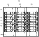
- an energy storage system includes a plurality of battery packs 100 according to an embodiment of the present disclosure.
- the battery pack 100 includes a pack housing 110, battery modules 120, a water tank 130, a controller 140, a coolant tube 150 and a sensor 160.
- the pack housing 110 is an approximately rectangular frame that defines the appearance of the battery pack 100, and has a space formed therein so that the plurality of battery modules 120, the water tank 130, the controller 140, the coolant tube 150 and the sensor 160 may be installed therein.
- the battery module 120 is provided in plural, and the plurality of battery modules 120 are vertically stacked in the pack housing 110 to form a single module stack. The specific structure of the battery module 120 will be described later in detail with reference to FIGS. 4 to 10 .
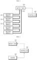
- the water tank 130 is provided inside the pack housing 110 and stores a water coolant that is to be supplied to the battery module 120 when a thermal runaway phenomenon occurs at the battery module 120.
- the water tank 130 may be disposed above the module stack for quick and smooth supply of coolant. In this case, even though a separate coolant pump is not used, the coolant may be rapidly supplied into the battery module 120 by free fall and water pressure of the coolant. Of course, a separate coolant pump may also be applied to the water tank 130 to supply the coolant more quickly and smoothly.
- the controller 140 may be connected to the sensor 160 and the water tank 130 and output a control signal to open the water tank 130 according to the sensing signal of the sensor 160.
- the controller 140 may additionally perform a function as a battery management system (BMS) that is connected to each battery module 120 to manage charging and discharging thereof, in addition to the above function.
- BMS battery management system
- the controller 140 outputs a control signal to open the water tank 130 when detecting gas or a temperature rise above a reference value inside the battery pack 100 due to a thermal runaway phenomenon occurring in at least one of the plurality of battery modules 120, and allows the coolant to be supplied into the battery module 120 accordingly.
- the coolant is sequentially supplied from a battery module 120 located at a relatively upper portion to a battery module 120 located at a relatively lower portion.
- the flame in the battery modules 120 is extinguished and also the battery modules 120 are cooled, thereby preventing the thermal runaway phenomenon from spreading throughout the battery pack 100.
- the coolant tube 150 connects the water tank 130 and the battery module 120 to each other, and functions as a passage for carrying the coolant supplied from the water tank 130 to the battery module 120. To perform this function, one end of the coolant tube 150 is connected to the water tank 130, and the other end of the coolant tube 150 is branched by the number of the battery modules 120 and connected to the plurality of battery modules 120, respectively.
- the sensor 160 detects a temperature rise and/or a gas ejection and transmits a detection signal to the controller 140.
- the sensor 160 may be a temperature sensor or a gas detection sensor, or a combination of the temperature sensor and the gas detection sensor.
- the sensor 160 is installed inside the pack housing 110 to detect temperature rise or gas generation inside the battery pack 100.
- the sensor 160 may be attached to an inner side or outer side of each of the plurality of battery modules 120 to quickly sense the temperature of the battery module 120 and/or gas generated from the battery module 120.
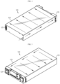
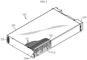
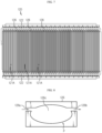
- the battery module 120 may be implemented to include a plurality of battery cells 121, a bus bar frame 122, a module housing 123, an air inlet 124, an air outlet 125 and an expansion pad 127.
- the battery module 120 may further include a swelling absorption pad 126 in addition to the above components.
- the battery cell 121 is provided in plural, and the plurality of battery cells 121 are stacked to form one unit module 121A. Also, a plurality of unit modules 121A are stacked to form a single unit module stack. As the battery cell 121, for example, a pouchtype battery cell may be applied.
- the battery cell 121 includes a pair of electrode leads 121a respectively drawn out at both sides thereof in a longitudinal direction.
- the bus bar frame 122 is provided in a pair, and the pair of bus bar frames 122 cover one side and the other side of the unit module stack in a width direction.
- the electrode lead of the battery cell 121 is drawn through a slit formed at the bus bar frame 122, and is bent and fixed by welding or the like onto the bus bar frame 122. That is, the plurality of battery cells 121 may be electrically connected by the bus bar frame 122.
- the module housing 123 has a substantially rectangular parallelepiped shape, and accommodates the unit module stack therein.
- the air inlet 124 and the air outlet 125 are formed at one side and the other side of the module housing 123 in the longitudinal direction.
- the air inlet 124 is formed at one side of the module stack in the stacking direction, namely at one side of the battery module 120 in the longitudinal direction and has a hole shape formed through the module housing 123.
- the air outlet 125 is formed at the other side of the module stack in the stacking direction, namely at the other side of the battery module 120 in the longitudinal direction and is has a hole shape formed through the module housing 123.
- the air inlet 124 and the air outlet 125 are located at diagonally opposite sides along the longitudinal direction of the battery module 120.
- an empty space is formed between the bus bar frame 122 and the module housing 123. That is, the empty space in which air for cooling the battery cell 121 flows is formed between one of six surfaces of the module housing 123 facing one side and the other side of the battery cell 121 in the longitudinal direction and the bus bar frame 122. The empty space is formed at each of both sides of the battery module 120 in the width direction.
- the air inlet 124 is formed at a location corresponding to the empty space formed at one side of the battery module 120 in the width direction
- the air outlet 125 is formed at a location corresponding to the empty space formed at the other side of the battery module 120 in the width direction.
- the air introduced therein through the air inlet 124 cools the battery cell 121 while moving from the empty space formed at one side of the battery module 120 in the width direction to the empty space formed at the other side of the battery module 120 in the width direction, and then goes out of the battery module 120 through the air outlet 125. That is, the battery module 120 corresponds to an air-cooled battery module.
- the coolant tube 150 passes through the module housing 123 from one side or the other side of the module stack in the stacking direction and communicates with the empty space formed between the bus bar frame 122 and the module housing 123.
- a coolant tube insert hole 123a into which the coolant tube 150 may be inserted is formed at a surface among six surfaces of the module housing 123, where the air inlet 124 or the air outlet 125 is formed.
- the coolant tube insert hole 123a communicates with the empty space, and the coolant tube 150 is inserted into the battery module 120 through the coolant tube insert hole 123a.
- the coolant tube insert hole 123a may be formed at a side opposite to the air inlet 124 or the air outlet 125 along the width direction of the battery module 120.
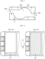
- the coolant introduced into the battery module 120 through the coolant tube 150 flows from the empty space formed at one side of the battery module 120 in the width direction to the empty space formed at the other side of the battery module 120 in the width direction to fill the inside of the battery module 120, as is shown in FIGS. 4 and 5 .
- the battery module 120 may include a swelling absorption pad 126 interposed between unit modules 121A of the module stack.
- the swelling absorption pad 126 may include, for example, materials such as silicon, graphite, expanded polypropylene (EPP), expanded polystylene (EPS), and the like, and has elasticity to absorb volume expansion of the battery cell 121 caused by swelling.
- the swelling absorption pad 126 includes a coolant channel P that provides a path through which the coolants may flow, so that the coolant may cool the battery cell 121 while passing between unit modules 121A adjacent to each other.
- the coolant channel P includes an input port 126a formed at one side of the swelling absorption pad 126 in the longitudinal direction, an output port 126b formed at the other side of the swelling absorption pad 126 in the longitudinal direction, and a cooling portion 126c connecting the input port 126a and the output port 126b to each other.
- the coolant channel P is open so that the coolant flowing through the coolant channel P directly contacts the pair of battery cells 121 in contact with the swelling absorption pad 126.
- the coolant flowing into the empty space formed at one side of the battery module 120 in the width direction sequentially passes through the input port 126a, the cooling portion 126c and the output port 126b, and moves to the empty space formed at the other side of the battery module 120 in the width direction to come into contact with the battery cell 121, thereby cooling the battery cell 121.
- the cooling portion 126c has a greater sectional area than the input port 126a and the output port 126b so that the coolant entering between the battery cells 121 adjacent to each other through the input port 126a may stay as long as possible.
- the coolant introduced through the input port 126a has a slow flow rate in the cooling portion 126c and has sufficient time to contact the battery cell 121. After completely exchanging heat with the battery cell 121, the coolant exits through the output port 126b.
- the input port 126a may be located higher than the output port 126b. If the input port 126a may be located higher than the output port 126b as described above, the coolant may flow more smoothly, thereby improving the cooling efficiency.
- the expansion pad 127 is disposed inside the air inlet 124 and the air outlet 125, and has a size smaller than the opened area of the air inlet 124 and the air outlet 125.
- the expansion pad 127 preferably has a size of less than 30% compared to the opened area of the air inlet 124 and air outlet 125 so that the air may flow through the air inlet 124 and the air outlet 125 smoothly when the battery module 120 is normally used.
- the expansion pad 127 is expanded by contacting the coolant introduced into the battery module 120 to close the air inlet 124 and the air outlet 125.
- the expansion pad 126 contains a resin that exhibits a very large expansion rate when absorbing moisture, for example a resin that increases in volume by at least two times or more compared to the initial volume when a sufficient amount of moisture is provided thereto.
- a resin used for the expansion pad 127 a polyester staple fiber is mentioned, for example.
- the expansion pad 127 By applying the expansion pad 127, when a thermal runaway phenomenon occurs in at least some battery modules 120 and thus a coolant is introduced into the battery modules 120, the air inlet 124 and the air outlet 125 are closed. If the air inlet 124 and the air outlet 125 are closed as above, the coolant introduced into the battery module 120 does not escape to the outside but stays inside the battery modules 120, thereby quickly resolving the thermal runaway phenomenon occurring in the battery modules 120.
- the battery pack according to another embodiment of the present disclosure is different from the battery pack 100 according to an embodiment of the present disclosure described above only in the point that a valve 170 is installed inside the coolant tube 150, and other components are substantially the same.
- the valve 170 is provided in plural as much as the number of the plurality of battery modules 120, and the valves 170 are respectively installed adjacent to the plurality of battery modules 120 to individually allow or block the flow of coolant flowing into the plurality of battery modules 120.
- At least one sensor 160 is provided for each battery module 120.
- the sensor 160 is provided for every battery module 120, it is possible to input the coolant only to some battery modules 120 in which a thermal runaway phenomenon occurs.
- the controller 140 determines that a thermal runaway phenomenon occurs in the battery modules 120 to which the sensors 160 sending the detection signal are attached, and opens the valves 170 installed adjacent to the battery modules 120 where the thermal runaway phenomenon occurs among the plurality of valves 170 so that the coolant may be put thereto.
Landscapes
- Chemical & Material Sciences (AREA)
- Chemical Kinetics & Catalysis (AREA)
- Electrochemistry (AREA)
- General Chemical & Material Sciences (AREA)
- Engineering & Computer Science (AREA)
- Manufacturing & Machinery (AREA)
- Automation & Control Theory (AREA)
- Secondary Cells (AREA)
- Battery Mounting, Suspending (AREA)
- Connection Of Batteries Or Terminals (AREA)
Claims (10)
- Luftgekühltes Batteriemodul (120), umfassend:einen Einheitsmodulstapel, welcher durch ein Stapeln einer Mehrzahl von Einheitsmodulen (121A) gebildet ist, wobei jedes Einheitsmodul (121A) eine Mehrzahl von Batteriezellen (121) aufweist, welche aneinander gestapelt sind,ein Anschwellabsorptionskissen (126), welches zwischen den einander benachbarten Einheitsmodulen (121A) eingefügt ist; undein Modulgehäuse (123), welches dazu eingerichtet ist, den Einheitsmodulstapel und das Anschwellabsorptionskissen (126) aufzunehmen,wobei das Anschwellabsorptionskissen (126) einen Wasserkühlmittelkanal (P) aufweist, welcher derart gebildet ist, dass er sich entlang einer longitudinalen Richtung davon erstreckt,wobei das luftgekühlte Batteriemodul (120) umfasst:einen Lufteinlass (124), welcher in der Stapelrichtung an einer Seite des Einheitsmodulstapels durch das Modulgehäuse (123) gebildet ist; undeinen Luftauslass (125), welcher in der Stapelrichtung an der anderen Seite des Einheitsmodulstapels durch das Modulgehäuse (123) gebildet ist,wobei das luftgekühlte Batteriemodul (120) ein Ausdehnungskissen (127) umfasst, welches innerhalb des Lufteinlasses (124) und des Luftauslasses (125) angeordnet ist und dazu eingerichtet ist, sich aufgrund des Kontakts mit einem in das luftgekühlte Batteriemodul (120) eingeleiteten Wasserkühlmittel auszudehnen, um den Lufteinlass (124) und den Luftauslass (125) zu schließen.
- Luftgekühltes Batteriemodul (120) nach Anspruch 1,
wobei der Kühlmittelkanal (P) umfasst:eine Einlassöffnung (126a), welche in der longitudinalen Richtung an einer Seite des Anschwellabsorptionskissens (126) bereitgestellt ist;eine Auslassöffnung (126b), welche in der longitudinalen Richtung an der anderen Seite des Anschwellabsorptionskissens (126) bereitgestellt ist; undeinen Kühlabschnitt (126c), welcher dazu eingerichtet ist, die Einlassöffnung (126a) und die Auslassöffnung (126b) miteinander zu verbinden, und welcher eine größere Querschnittsfläche aufweist als die Einlassöffnung (126a) und die Auslassöffnung (126b). - Luftgekühltes Batteriemodul (120) nach Anspruch 1,
wobei der Kühlmittelkanal (P) offen ist, so dass ein Wasserkühlmittel, welches durch den Kühlmittelkanal (P) strömt, ein Paar von Batteriezellen (121) in Kontakt mit dem Anschwellabsorptionskissen (126) direkt kontaktiert. - Luftgekühltes Batteriemodul (120) nach Anspruch 2,
wobei die Einlassöffnung (126a) höher angeordnet ist als die Auslassöffnung (126b). - Luftgekühltes Batteriemodul (120) nach Anspruch 1,
wobei das Batteriemodul (120) ein Paar von Sammelschienenrahmen (122) umfasst, welche in einer Breitenrichtung mit einer Seite bzw. der anderen Seite des Einheitsmodulstapels gekoppelt sind. - Luftgekühltes Batteriemodul (120) nach Anspruch 5,
wobei der Lufteinlass (124) und der Luftauslass (125) an Stellen gebildet sind, welche einem leeren Raum entsprechen, welcher zwischen dem Sammelschienenrahmen (122) und dem Modulgehäuse (123) gebildet ist. - Luftgekühltes Batteriemodul (120) nach Anspruch 5,
wobei das luftgekühlte Batteriemodul (120) ein Wasserkühlmittelrohreinsetzloch (123a) umfasst, welches in der Stapelrichtung von einer Seite oder der anderen Seite des Einheitsmodulstapels durch das Modulgehäuse (123) gebildet ist, um mit einem leeren Raum zu kommunizieren, welcher zwischen dem Sammelschienenrahmen (122) und dem Modulgehäuse (123) gebildet ist. - Batteriepack (100), umfassend:ein Packgehäuse (110);eine Mehrzahl von luftgekühlten Batteriemodulen (120) nach einem der vorhergehenden Ansprüche 1 bis 7, welche in dem Packgehäuse (110) gestapelt sind;einen Wassertank (130), welcher oberhalb eines Modulstapels angeordnet ist, der die Mehrzahl von Batteriemodulen (120) umfasst;ein Kühlmittelrohr (150), welches dazu eingerichtet ist, den Wassertank (130) und die Batteriemodule (120) miteinander zu verbinden;wenigstens einen Sensor (160), welcher innerhalb des Packgehäuses (110) installiert ist, um ein Phänomen eines thermischen Durchgehens zu detektieren, welches in wenigstens einem Teil der Mehrzahl von luftgekühlten Batteriemodulen (120) auftritt; undeine Steuereinrichtung (140), welche dazu eingerichtet ist, ein Steuersignal zum Einleiten eines Wasserkühlmittels in das Batteriemodul (120) durch das Kühlmittelrohr (150) auszugeben, wenn ein Phänomen eines thermischen Durchgehens durch den Sensor (160) detektiert wird.
- Batteriepack (100) nach Anspruch 8,wobei der Batteriepack (100) eine Mehrzahl von Ventilen (170) umfasst, welche in dem Kühlmittelrohr (150) installiert sind, unddie Mehrzahl von Ventilen (170) jeweils benachbart zu der Mehrzahl von Batteriemodulen (120) des Modulstapels installiert ist, um die Strömung von in die Mehrzahl von Batteriemodulen (120) eingeführtem Kühlmittel individuell zu erlauben oder zu blockieren.
- Energiespeichersystem (ESS), umfassend eine Mehrzahl von Batteriepacks (100) nach einem der Ansprüche 8 bis 9.
Priority Applications (2)
| Application Number | Priority Date | Filing Date | Title |
|---|---|---|---|
| EP24194326.5A EP4438135A3 (de) | 2019-05-30 | 2020-04-01 | Batteriemodul mit pfad, durch den bei thermischem durchgehen das intern gespeiste kühlmittel fliessen kann, und batteriepack und ess damit |
| EP23206723.1A EP4292674A3 (de) | 2019-05-30 | 2020-04-01 | Batteriemodul mit pfad, durch den bei thermischem durchgehen das intern gespeiste kühlmittel fliessen kann, und batteriepack und ess damit |
Applications Claiming Priority (3)
| Application Number | Priority Date | Filing Date | Title |
|---|---|---|---|
| KR1020190063999A KR102380444B1 (ko) | 2019-05-30 | 2019-05-30 | 열 폭주 현상 발생 시 내부로 투입된 냉각수가 흐를 수 있는 경로를 갖는 배터리 모듈, 이를 포함하는 배터리 팩 및 ess |
| KR1020190068053A KR102380446B1 (ko) | 2019-06-10 | 2019-06-10 | 열 폭주 현상 발생 시 냉각수가 배터리 모듈의 내부로 투입될 수 있는 구조를 갖는 배터리 팩 및 이를 포함하는 ess |
| PCT/KR2020/004477 WO2020242035A1 (ko) | 2019-05-30 | 2020-04-01 | 열 폭주 현상 발생 시 내부로 투입된 냉각수가 흐를 수 있는 경로를 갖는 배터리 모듈, 이를 포함하는 배터리 팩 및 ess |
Related Child Applications (3)
| Application Number | Title | Priority Date | Filing Date |
|---|---|---|---|
| EP24194326.5A Division EP4438135A3 (de) | 2019-05-30 | 2020-04-01 | Batteriemodul mit pfad, durch den bei thermischem durchgehen das intern gespeiste kühlmittel fliessen kann, und batteriepack und ess damit |
| EP23206723.1A Division EP4292674A3 (de) | 2019-05-30 | 2020-04-01 | Batteriemodul mit pfad, durch den bei thermischem durchgehen das intern gespeiste kühlmittel fliessen kann, und batteriepack und ess damit |
| EP23206723.1A Division-Into EP4292674A3 (de) | 2019-05-30 | 2020-04-01 | Batteriemodul mit pfad, durch den bei thermischem durchgehen das intern gespeiste kühlmittel fliessen kann, und batteriepack und ess damit |
Publications (3)
| Publication Number | Publication Date |
|---|---|
| EP3840109A1 EP3840109A1 (de) | 2021-06-23 |
| EP3840109A4 EP3840109A4 (de) | 2022-03-16 |
| EP3840109B1 true EP3840109B1 (de) | 2024-08-14 |
Family
ID=73506659
Family Applications (3)
| Application Number | Title | Priority Date | Filing Date |
|---|---|---|---|
| EP20815309.8A Active EP3840109B1 (de) | 2019-05-30 | 2020-04-01 | Batteriemodul mit pfad, durch den bei thermischem durchgehen das innen zugeführte kühlmittel fliessen kann, und batteriesatz und ess damit |
| EP23206723.1A Withdrawn EP4292674A3 (de) | 2019-05-30 | 2020-04-01 | Batteriemodul mit pfad, durch den bei thermischem durchgehen das intern gespeiste kühlmittel fliessen kann, und batteriepack und ess damit |
| EP24194326.5A Pending EP4438135A3 (de) | 2019-05-30 | 2020-04-01 | Batteriemodul mit pfad, durch den bei thermischem durchgehen das intern gespeiste kühlmittel fliessen kann, und batteriepack und ess damit |
Family Applications After (2)
| Application Number | Title | Priority Date | Filing Date |
|---|---|---|---|
| EP23206723.1A Withdrawn EP4292674A3 (de) | 2019-05-30 | 2020-04-01 | Batteriemodul mit pfad, durch den bei thermischem durchgehen das intern gespeiste kühlmittel fliessen kann, und batteriepack und ess damit |
| EP24194326.5A Pending EP4438135A3 (de) | 2019-05-30 | 2020-04-01 | Batteriemodul mit pfad, durch den bei thermischem durchgehen das intern gespeiste kühlmittel fliessen kann, und batteriepack und ess damit |
Country Status (10)
| Country | Link |
|---|---|
| US (1) | US11450908B2 (de) |
| EP (3) | EP3840109B1 (de) |
| JP (1) | JP7179150B2 (de) |
| CN (2) | CN112018287B (de) |
| AU (1) | AU2020282883B2 (de) |
| DE (3) | DE202020006097U1 (de) |
| ES (1) | ES2986734T3 (de) |
| HU (1) | HUE068258T2 (de) |
| PL (1) | PL3840109T3 (de) |
| WO (1) | WO2020242035A1 (de) |
Families Citing this family (12)
| Publication number | Priority date | Publication date | Assignee | Title |
|---|---|---|---|---|
| WO2020242035A1 (ko) | 2019-05-30 | 2020-12-03 | 주식회사 엘지화학 | 열 폭주 현상 발생 시 내부로 투입된 냉각수가 흐를 수 있는 경로를 갖는 배터리 모듈, 이를 포함하는 배터리 팩 및 ess |
| KR102791885B1 (ko) | 2019-07-08 | 2025-04-04 | 주식회사 엘지에너지솔루션 | 열 폭주 현상 발생 시 냉각수가 내부로 투입될 수 있는 구조를 갖는 배터리 모듈, 이를 포함하는 배터리 팩 및 에너지저장장치 |
| DE102019216050A1 (de) * | 2019-10-17 | 2021-04-22 | Kautex Textron Gmbh & Co. Kg | Gehäusevorrichtung für Traktionsbatterie mit fluidbasierter Kühlung mit Verdampfungsvorrichtung mit Mikrokanälen |
| KR102882553B1 (ko) * | 2020-02-27 | 2025-11-06 | 주식회사 엘지에너지솔루션 | 신속한 냉각이 가능한 구조를 갖는 배터리 모듈 및 이를 포함하는 ess |
| EP3998673A1 (de) * | 2021-02-19 | 2022-05-18 | Lilium eAircraft GmbH | Batteriemodul |
| CN115692911B (zh) * | 2021-07-30 | 2023-10-20 | 宁德时代新能源科技股份有限公司 | 电池和用电装置 |
| CN113572186A (zh) * | 2021-08-19 | 2021-10-29 | 厦门海辰新能源科技有限公司 | 储能系统 |
| KR102856932B1 (ko) * | 2022-02-08 | 2025-09-05 | 주식회사 엘지에너지솔루션 | 배터리 랙 및 이를 포함하는 전력 저장 장치 |
| WO2023171950A1 (ko) * | 2022-03-10 | 2023-09-14 | 주식회사 엘지에너지솔루션 | 냉각 시스템을 포함하는 디바이스 |
| KR20230172055A (ko) * | 2022-06-14 | 2023-12-22 | 주식회사 엘지에너지솔루션 | 화재 안전성을 개선한 배터리 팩 |
| WO2024133146A2 (en) * | 2022-12-22 | 2024-06-27 | Polarium Energy Solutions Ab | Energy storage system comprising a cooling system |
| EP4709490A1 (de) * | 2023-07-14 | 2026-03-18 | Tyco Fire Products LP | Mehrzonenschnittstellenmodul für brandunterdrückungssystem |
Family Cites Families (46)
| Publication number | Priority date | Publication date | Assignee | Title |
|---|---|---|---|---|
| KR950015887A (ko) | 1993-11-08 | 1995-06-17 | 조백제 | 관로 관구마개 |
| JP3451142B2 (ja) | 1994-11-18 | 2003-09-29 | 本田技研工業株式会社 | 温度制御機構を備えたバッテリ組立体 |
| JPH10208781A (ja) | 1997-01-20 | 1998-08-07 | Mitsubishi Motors Corp | バッテリ冷却装置 |
| JP2000048867A (ja) * | 1998-07-31 | 2000-02-18 | Toyota Motor Corp | 組電池 |
| KR100369068B1 (ko) * | 1999-04-16 | 2003-01-24 | 삼성에스디아이 주식회사 | 원통형 2차 전지 |
| EP1111215B1 (de) | 1999-12-21 | 2004-09-08 | Ford Global Technologies, Inc. | Thermostateinheit für einen Kühlkreislauf |
| JP2003346922A (ja) | 2002-05-28 | 2003-12-05 | Mitsubishi Heavy Ind Ltd | 蓄電装置の温度調整装置及びその方法並びに蓄電装置 |
| JP5632402B2 (ja) | 2004-11-30 | 2014-11-26 | 日本電気株式会社 | フィルム外装電気デバイス集合体 |
| JP4661895B2 (ja) | 2008-04-02 | 2011-03-30 | 株式会社デンソー | 電池冷却装置 |
| KR20110024954A (ko) | 2009-09-03 | 2011-03-09 | 삼성전자주식회사 | 냉각용 유로를 갖는 이차 전지 모듈 |
| JP2011096465A (ja) | 2009-10-28 | 2011-05-12 | Tokyo R & D Co Ltd | 冷却板及びバッテリーシステム |
| EP2369657B1 (de) * | 2010-03-23 | 2014-12-24 | Jones, William E. M. | Batteriewässerungssystem |
| JP2012104225A (ja) | 2010-11-05 | 2012-05-31 | Kawasaki Heavy Ind Ltd | 電池モジュール、電池モジュールの製造方法および電池用スペーサ |
| JP2013048082A (ja) | 2011-07-25 | 2013-03-07 | Gs Yuasa Corp | 鉛蓄電池 |
| JP5182444B2 (ja) | 2011-07-28 | 2013-04-17 | 株式会社豊田自動織機 | 電池用温調機構 |
| JP5772428B2 (ja) | 2011-09-15 | 2015-09-02 | 日産自動車株式会社 | 二次電池の冷却装置 |
| KR20130033597A (ko) | 2011-09-27 | 2013-04-04 | 에스케이이노베이션 주식회사 | 이차 전지 모듈 |
| JP5856472B2 (ja) | 2011-12-22 | 2016-02-09 | 積水化学工業株式会社 | 蓄電池の設置構造 |
| JP2013161635A (ja) | 2012-02-03 | 2013-08-19 | Toyota Industries Corp | 端子接続部材、端子接続部材の製造方法及び蓄電装置並びに移動体 |
| KR101255250B1 (ko) * | 2012-03-23 | 2013-04-16 | 삼성에스디아이 주식회사 | 전지 모듈 |
| JP2014060012A (ja) | 2012-09-14 | 2014-04-03 | Nissan Motor Co Ltd | 積層構造電池 |
| JP2014127403A (ja) | 2012-12-27 | 2014-07-07 | Mitsubishi Heavy Ind Ltd | 電池モジュール |
| JP2014216248A (ja) | 2013-04-26 | 2014-11-17 | 三菱自動車工業株式会社 | バッテリケース |
| TWI489674B (zh) * | 2014-01-13 | 2015-06-21 | 新普科技股份有限公司 | 散熱件及其組成之電池模組 |
| US9322328B2 (en) | 2014-03-14 | 2016-04-26 | Chung-Shan Institute Of Science And Technology, Armaments Bureau, M.N.D | Internal cooling passage structure for rotary engine |
| JP2015220177A (ja) | 2014-05-20 | 2015-12-07 | 株式会社Gsユアサ | 蓄電装置 |
| JP2016002419A (ja) | 2014-06-19 | 2016-01-12 | Necエンジニアリング株式会社 | 蓄電装置の消火システム、及び蓄電装置の消火方法 |
| KR20160069807A (ko) * | 2014-12-09 | 2016-06-17 | 삼성에스디아이 주식회사 | 전지 모듈 |
| JP2018113097A (ja) | 2015-05-21 | 2018-07-19 | パナソニックIpマネジメント株式会社 | 組電池 |
| KR102553028B1 (ko) | 2016-01-12 | 2023-07-06 | 삼성전자주식회사 | 모듈의 균일한 냉각을 위한 배터리 팩 및 이의 냉각 방법 |
| US10326171B2 (en) * | 2016-03-24 | 2019-06-18 | Flow-Rite Controls, Ltd. | Intelligent monitoring systems for liquid electrolyte batteries |
| KR102256604B1 (ko) | 2016-05-31 | 2021-05-26 | 주식회사 엘지에너지솔루션 | 배터리 모듈, 이러한 배터리 모듈을 포함하는 배터리 팩 및 이러한 배터리 팩을 포함하는 자동차 |
| JP6540628B2 (ja) | 2016-07-29 | 2019-07-10 | 株式会社デンソー | 電池パック |
| JP6779079B2 (ja) | 2016-09-26 | 2020-11-04 | 日本ドライケミカル株式会社 | 二次電池の熱暴走抑止システム |
| DE102016219284A1 (de) | 2016-10-05 | 2018-04-05 | Bayerische Motoren Werke Aktiengesellschaft | Elektrischer Energiespeicher mit einer Notkühleinrichtung |
| EP3316344B1 (de) | 2016-11-01 | 2018-09-26 | Samsung SDI Co., Ltd. | Batteriemodul |
| KR20180056219A (ko) | 2016-11-18 | 2018-05-28 | 삼성전자주식회사 | 스페이서 및 이를 포함하는 배터리 어셈블리 |
| KR102155330B1 (ko) | 2016-11-29 | 2020-09-11 | 주식회사 엘지화학 | 공냉식 배터리 모듈 |
| KR102663216B1 (ko) * | 2016-12-13 | 2024-05-02 | 현대자동차주식회사 | 배터리 구조 |
| JP2018133134A (ja) | 2017-02-13 | 2018-08-23 | 三菱自動車工業株式会社 | 二次電池冷却機構 |
| SE540767C2 (en) | 2017-03-06 | 2018-11-06 | Scania Cv Ab | A thermostat device for a cooling system |
| KR101780775B1 (ko) * | 2017-03-17 | 2017-10-10 | 주식회사 광운기술 | 점검 및 유지보수가 용이한 케이블 트레이용 차열 차염 부재 |
| KR102437707B1 (ko) | 2017-04-07 | 2022-08-29 | 현대자동차주식회사 | 차량용 배터리 화재 진화 시스템 및 제어방법 |
| KR102000621B1 (ko) | 2017-11-30 | 2019-07-16 | 코멧테크놀로지스코리아 주식회사 | Rf전력분배장치 및 rf전력분배방법 |
| KR20190068053A (ko) | 2017-12-08 | 2019-06-18 | 주식회사 피코그램 | Ro필터용 정수 량 확인 및 농축수 배출량 조절밸브 |
| WO2020242035A1 (ko) | 2019-05-30 | 2020-12-03 | 주식회사 엘지화학 | 열 폭주 현상 발생 시 내부로 투입된 냉각수가 흐를 수 있는 경로를 갖는 배터리 모듈, 이를 포함하는 배터리 팩 및 ess |
-
2020
- 2020-04-01 WO PCT/KR2020/004477 patent/WO2020242035A1/ko not_active Ceased
- 2020-04-01 DE DE202020006097.6U patent/DE202020006097U1/de active Active
- 2020-04-01 DE DE202020006013.5U patent/DE202020006013U1/de active Active
- 2020-04-01 US US16/972,839 patent/US11450908B2/en active Active
- 2020-04-01 HU HUE20815309A patent/HUE068258T2/hu unknown
- 2020-04-01 PL PL20815309.8T patent/PL3840109T3/pl unknown
- 2020-04-01 EP EP20815309.8A patent/EP3840109B1/de active Active
- 2020-04-01 ES ES20815309T patent/ES2986734T3/es active Active
- 2020-04-01 EP EP23206723.1A patent/EP4292674A3/de not_active Withdrawn
- 2020-04-01 EP EP24194326.5A patent/EP4438135A3/de active Pending
- 2020-04-01 JP JP2021500621A patent/JP7179150B2/ja active Active
- 2020-04-01 DE DE202020006102.6U patent/DE202020006102U1/de active Active
- 2020-04-01 AU AU2020282883A patent/AU2020282883B2/en active Active
- 2020-05-29 CN CN202010474828.6A patent/CN112018287B/zh active Active
- 2020-05-29 CN CN202020961677.2U patent/CN212967883U/zh active Active
Also Published As
| Publication number | Publication date |
|---|---|
| DE202020006102U1 (de) | 2025-03-07 |
| PL3840109T3 (pl) | 2024-11-04 |
| JP7179150B2 (ja) | 2022-11-28 |
| EP4292674A2 (de) | 2023-12-20 |
| AU2020282883B2 (en) | 2025-09-04 |
| EP4438135A3 (de) | 2025-01-15 |
| JP2021530090A (ja) | 2021-11-04 |
| DE202020006013U1 (de) | 2024-03-19 |
| EP4438135A2 (de) | 2024-10-02 |
| ES2986734T3 (es) | 2024-11-12 |
| DE202020006097U1 (de) | 2025-02-26 |
| US20210249712A1 (en) | 2021-08-12 |
| WO2020242035A1 (ko) | 2020-12-03 |
| CN112018287A (zh) | 2020-12-01 |
| US11450908B2 (en) | 2022-09-20 |
| CN112018287B (zh) | 2023-12-15 |
| EP3840109A1 (de) | 2021-06-23 |
| CN212967883U (zh) | 2021-04-13 |
| AU2020282883A1 (en) | 2021-04-29 |
| EP3840109A4 (de) | 2022-03-16 |
| EP4292674A3 (de) | 2024-03-20 |
| HUE068258T2 (hu) | 2024-12-28 |
Similar Documents
| Publication | Publication Date | Title |
|---|---|---|
| EP3840109B1 (de) | Batteriemodul mit pfad, durch den bei thermischem durchgehen das innen zugeführte kühlmittel fliessen kann, und batteriesatz und ess damit | |
| EP4027435B1 (de) | Batteriepack mit einer struktur, die bei auftreten eines thermischen durchgehens das einleiten von kühlwasser in das batteriemodul ermöglicht, sowie ein energiespeichersystem, das dieses umfasst | |
| EP3955371B1 (de) | Ess mit superabsorbierender folie | |
| KR102791885B1 (ko) | 열 폭주 현상 발생 시 냉각수가 내부로 투입될 수 있는 구조를 갖는 배터리 모듈, 이를 포함하는 배터리 팩 및 에너지저장장치 | |
| US12294109B2 (en) | Battery module having structure capable of delaying outflow of fire-fighting water injected therein in case of fire, and battery rack and energy storage device comprising same | |
| KR102380446B1 (ko) | 열 폭주 현상 발생 시 냉각수가 배터리 모듈의 내부로 투입될 수 있는 구조를 갖는 배터리 팩 및 이를 포함하는 ess | |
| KR102882553B1 (ko) | 신속한 냉각이 가능한 구조를 갖는 배터리 모듈 및 이를 포함하는 ess | |
| KR102380444B1 (ko) | 열 폭주 현상 발생 시 내부로 투입된 냉각수가 흐를 수 있는 경로를 갖는 배터리 모듈, 이를 포함하는 배터리 팩 및 ess | |
| KR102886572B1 (ko) | 스프링클러의 신속한 동작이 가능한 구조를 갖는 배터리 모듈 및 이를 포함하는 ess | |
| JP7345628B2 (ja) | 迅速に冷却可能な構造を有するバッテリーモジュール及びそれを含むエネルギー貯蔵システム | |
| JP2026502191A (ja) | バッテリアセンブリおよびこれを含むバッテリパック |
Legal Events
| Date | Code | Title | Description |
|---|---|---|---|
| REG | Reference to a national code |
Ref country code: DE Ref legal event code: R138 Ref document number: 202020006013 Country of ref document: DE Free format text: GERMAN DOCUMENT NUMBER IS 602020035885 |
|
| STAA | Information on the status of an ep patent application or granted ep patent |
Free format text: STATUS: THE INTERNATIONAL PUBLICATION HAS BEEN MADE |
|
| PUAI | Public reference made under article 153(3) epc to a published international application that has entered the european phase |
Free format text: ORIGINAL CODE: 0009012 |
|
| STAA | Information on the status of an ep patent application or granted ep patent |
Free format text: STATUS: REQUEST FOR EXAMINATION WAS MADE |
|
| 17P | Request for examination filed |
Effective date: 20210315 |
|
| AK | Designated contracting states |
Kind code of ref document: A1 Designated state(s): AL AT BE BG CH CY CZ DE DK EE ES FI FR GB GR HR HU IE IS IT LI LT LU LV MC MK MT NL NO PL PT RO RS SE SI SK SM TR |
|
| RIC1 | Information provided on ipc code assigned before grant |
Ipc: A62C 3/16 20060101ALI20211029BHEP Ipc: A62C 2/06 20060101ALI20211029BHEP Ipc: H01M 10/48 20060101ALI20211029BHEP Ipc: H01M 10/63 20140101ALI20211029BHEP Ipc: H01M 10/613 20140101ALI20211029BHEP Ipc: H01M 10/6567 20140101ALI20211029BHEP Ipc: H01M 10/6557 20140101ALI20211029BHEP Ipc: H01M 10/6555 20140101ALI20211029BHEP Ipc: H01M 10/42 20060101ALI20211029BHEP Ipc: H01M 50/242 20210101ALI20211029BHEP Ipc: H01M 50/209 20210101AFI20211029BHEP |
|
| RAP1 | Party data changed (applicant data changed or rights of an application transferred) |
Owner name: LG ENERGY SOLUTION LTD. |
|
| REG | Reference to a national code |
Ref legal event code: R079 Ipc: H01M0050209000 Ref country code: DE Ref legal event code: R079 Ref document number: 602020035885 Country of ref document: DE Free format text: PREVIOUS MAIN CLASS: H01M0010656700 Ipc: H01M0050209000 |
|
| A4 | Supplementary search report drawn up and despatched |
Effective date: 20220215 |
|
| RIC1 | Information provided on ipc code assigned before grant |
Ipc: A62C 3/16 20060101ALI20220209BHEP Ipc: A62C 2/06 20060101ALI20220209BHEP Ipc: H01M 10/48 20060101ALI20220209BHEP Ipc: H01M 10/63 20140101ALI20220209BHEP Ipc: H01M 10/613 20140101ALI20220209BHEP Ipc: H01M 10/6567 20140101ALI20220209BHEP Ipc: H01M 10/6557 20140101ALI20220209BHEP Ipc: H01M 10/6555 20140101ALI20220209BHEP Ipc: H01M 10/42 20060101ALI20220209BHEP Ipc: H01M 50/242 20210101ALI20220209BHEP Ipc: H01M 50/209 20210101AFI20220209BHEP |
|
| RAP3 | Party data changed (applicant data changed or rights of an application transferred) |
Owner name: LG ENERGY SOLUTION, LTD. |
|
| DAV | Request for validation of the european patent (deleted) | ||
| DAX | Request for extension of the european patent (deleted) | ||
| STAA | Information on the status of an ep patent application or granted ep patent |
Free format text: STATUS: EXAMINATION IS IN PROGRESS |
|
| 17Q | First examination report despatched |
Effective date: 20231026 |
|
| GRAP | Despatch of communication of intention to grant a patent |
Free format text: ORIGINAL CODE: EPIDOSNIGR1 |
|
| STAA | Information on the status of an ep patent application or granted ep patent |
Free format text: STATUS: GRANT OF PATENT IS INTENDED |
|
| INTG | Intention to grant announced |
Effective date: 20240508 |
|
| GRAS | Grant fee paid |
Free format text: ORIGINAL CODE: EPIDOSNIGR3 |
|
| GRAA | (expected) grant |
Free format text: ORIGINAL CODE: 0009210 |
|
| STAA | Information on the status of an ep patent application or granted ep patent |
Free format text: STATUS: THE PATENT HAS BEEN GRANTED |
|
| P01 | Opt-out of the competence of the unified patent court (upc) registered |
Free format text: CASE NUMBER: APP_33835/2024 Effective date: 20240606 |
|
| AK | Designated contracting states |
Kind code of ref document: B1 Designated state(s): AL AT BE BG CH CY CZ DE DK EE ES FI FR GB GR HR HU IE IS IT LI LT LU LV MC MK MT NL NO PL PT RO RS SE SI SK SM TR |
|
| REG | Reference to a national code |
Ref country code: GB Ref legal event code: FG4D |
|
| REG | Reference to a national code |
Ref country code: CH Ref legal event code: EP |
|
| REG | Reference to a national code |
Ref country code: DE Ref legal event code: R096 Ref document number: 602020035885 Country of ref document: DE |
|
| REG | Reference to a national code |
Ref country code: IE Ref legal event code: FG4D |
|
| REG | Reference to a national code |
Ref country code: NL Ref legal event code: FP |
|
| REG | Reference to a national code |
Ref country code: SE Ref legal event code: TRGR |
|
| REG | Reference to a national code |
Ref country code: ES Ref legal event code: FG2A Ref document number: 2986734 Country of ref document: ES Kind code of ref document: T3 Effective date: 20241112 |
|
| REG | Reference to a national code |
Ref country code: LT Ref legal event code: MG9D |
|
| REG | Reference to a national code |
Ref country code: HU Ref legal event code: AG4A Ref document number: E068258 Country of ref document: HU |
|
| PG25 | Lapsed in a contracting state [announced via postgrant information from national office to epo] |
Ref country code: NO Free format text: LAPSE BECAUSE OF FAILURE TO SUBMIT A TRANSLATION OF THE DESCRIPTION OR TO PAY THE FEE WITHIN THE PRESCRIBED TIME-LIMIT Effective date: 20241114 |
|
| REG | Reference to a national code |
Ref country code: AT Ref legal event code: MK05 Ref document number: 1714152 Country of ref document: AT Kind code of ref document: T Effective date: 20240814 |
|
| PG25 | Lapsed in a contracting state [announced via postgrant information from national office to epo] |
Ref country code: FI Free format text: LAPSE BECAUSE OF FAILURE TO SUBMIT A TRANSLATION OF THE DESCRIPTION OR TO PAY THE FEE WITHIN THE PRESCRIBED TIME-LIMIT Effective date: 20240814 Ref country code: GR Free format text: LAPSE BECAUSE OF FAILURE TO SUBMIT A TRANSLATION OF THE DESCRIPTION OR TO PAY THE FEE WITHIN THE PRESCRIBED TIME-LIMIT Effective date: 20241115 Ref country code: PT Free format text: LAPSE BECAUSE OF FAILURE TO SUBMIT A TRANSLATION OF THE DESCRIPTION OR TO PAY THE FEE WITHIN THE PRESCRIBED TIME-LIMIT Effective date: 20241216 |
|
| PG25 | Lapsed in a contracting state [announced via postgrant information from national office to epo] |
Ref country code: BG Free format text: LAPSE BECAUSE OF FAILURE TO SUBMIT A TRANSLATION OF THE DESCRIPTION OR TO PAY THE FEE WITHIN THE PRESCRIBED TIME-LIMIT Effective date: 20240814 |
|
| PG25 | Lapsed in a contracting state [announced via postgrant information from national office to epo] |
Ref country code: LV Free format text: LAPSE BECAUSE OF FAILURE TO SUBMIT A TRANSLATION OF THE DESCRIPTION OR TO PAY THE FEE WITHIN THE PRESCRIBED TIME-LIMIT Effective date: 20240814 |
|
| PG25 | Lapsed in a contracting state [announced via postgrant information from national office to epo] |
Ref country code: AT Free format text: LAPSE BECAUSE OF FAILURE TO SUBMIT A TRANSLATION OF THE DESCRIPTION OR TO PAY THE FEE WITHIN THE PRESCRIBED TIME-LIMIT Effective date: 20240814 Ref country code: IS Free format text: LAPSE BECAUSE OF FAILURE TO SUBMIT A TRANSLATION OF THE DESCRIPTION OR TO PAY THE FEE WITHIN THE PRESCRIBED TIME-LIMIT Effective date: 20241214 |
|
| PG25 | Lapsed in a contracting state [announced via postgrant information from national office to epo] |
Ref country code: HR Free format text: LAPSE BECAUSE OF FAILURE TO SUBMIT A TRANSLATION OF THE DESCRIPTION OR TO PAY THE FEE WITHIN THE PRESCRIBED TIME-LIMIT Effective date: 20240814 |
|
| PG25 | Lapsed in a contracting state [announced via postgrant information from national office to epo] |
Ref country code: RS Free format text: LAPSE BECAUSE OF FAILURE TO SUBMIT A TRANSLATION OF THE DESCRIPTION OR TO PAY THE FEE WITHIN THE PRESCRIBED TIME-LIMIT Effective date: 20241114 |
|
| PG25 | Lapsed in a contracting state [announced via postgrant information from national office to epo] |
Ref country code: RS Free format text: LAPSE BECAUSE OF FAILURE TO SUBMIT A TRANSLATION OF THE DESCRIPTION OR TO PAY THE FEE WITHIN THE PRESCRIBED TIME-LIMIT Effective date: 20241114 Ref country code: PT Free format text: LAPSE BECAUSE OF FAILURE TO SUBMIT A TRANSLATION OF THE DESCRIPTION OR TO PAY THE FEE WITHIN THE PRESCRIBED TIME-LIMIT Effective date: 20241216 Ref country code: NO Free format text: LAPSE BECAUSE OF FAILURE TO SUBMIT A TRANSLATION OF THE DESCRIPTION OR TO PAY THE FEE WITHIN THE PRESCRIBED TIME-LIMIT Effective date: 20241114 Ref country code: LV Free format text: LAPSE BECAUSE OF FAILURE TO SUBMIT A TRANSLATION OF THE DESCRIPTION OR TO PAY THE FEE WITHIN THE PRESCRIBED TIME-LIMIT Effective date: 20240814 Ref country code: IS Free format text: LAPSE BECAUSE OF FAILURE TO SUBMIT A TRANSLATION OF THE DESCRIPTION OR TO PAY THE FEE WITHIN THE PRESCRIBED TIME-LIMIT Effective date: 20241214 Ref country code: HR Free format text: LAPSE BECAUSE OF FAILURE TO SUBMIT A TRANSLATION OF THE DESCRIPTION OR TO PAY THE FEE WITHIN THE PRESCRIBED TIME-LIMIT Effective date: 20240814 Ref country code: GR Free format text: LAPSE BECAUSE OF FAILURE TO SUBMIT A TRANSLATION OF THE DESCRIPTION OR TO PAY THE FEE WITHIN THE PRESCRIBED TIME-LIMIT Effective date: 20241115 Ref country code: FI Free format text: LAPSE BECAUSE OF FAILURE TO SUBMIT A TRANSLATION OF THE DESCRIPTION OR TO PAY THE FEE WITHIN THE PRESCRIBED TIME-LIMIT Effective date: 20240814 Ref country code: BG Free format text: LAPSE BECAUSE OF FAILURE TO SUBMIT A TRANSLATION OF THE DESCRIPTION OR TO PAY THE FEE WITHIN THE PRESCRIBED TIME-LIMIT Effective date: 20240814 Ref country code: AT Free format text: LAPSE BECAUSE OF FAILURE TO SUBMIT A TRANSLATION OF THE DESCRIPTION OR TO PAY THE FEE WITHIN THE PRESCRIBED TIME-LIMIT Effective date: 20240814 |
|
| PG25 | Lapsed in a contracting state [announced via postgrant information from national office to epo] |
Ref country code: DK Free format text: LAPSE BECAUSE OF FAILURE TO SUBMIT A TRANSLATION OF THE DESCRIPTION OR TO PAY THE FEE WITHIN THE PRESCRIBED TIME-LIMIT Effective date: 20240814 Ref country code: RO Free format text: LAPSE BECAUSE OF FAILURE TO SUBMIT A TRANSLATION OF THE DESCRIPTION OR TO PAY THE FEE WITHIN THE PRESCRIBED TIME-LIMIT Effective date: 20240814 Ref country code: SM Free format text: LAPSE BECAUSE OF FAILURE TO SUBMIT A TRANSLATION OF THE DESCRIPTION OR TO PAY THE FEE WITHIN THE PRESCRIBED TIME-LIMIT Effective date: 20240814 |
|
| PG25 | Lapsed in a contracting state [announced via postgrant information from national office to epo] |
Ref country code: EE Free format text: LAPSE BECAUSE OF FAILURE TO SUBMIT A TRANSLATION OF THE DESCRIPTION OR TO PAY THE FEE WITHIN THE PRESCRIBED TIME-LIMIT Effective date: 20240814 |
|
| PG25 | Lapsed in a contracting state [announced via postgrant information from national office to epo] |
Ref country code: CZ Free format text: LAPSE BECAUSE OF FAILURE TO SUBMIT A TRANSLATION OF THE DESCRIPTION OR TO PAY THE FEE WITHIN THE PRESCRIBED TIME-LIMIT Effective date: 20240814 |
|
| PG25 | Lapsed in a contracting state [announced via postgrant information from national office to epo] |
Ref country code: SK Free format text: LAPSE BECAUSE OF FAILURE TO SUBMIT A TRANSLATION OF THE DESCRIPTION OR TO PAY THE FEE WITHIN THE PRESCRIBED TIME-LIMIT Effective date: 20240814 |
|
| PGFP | Annual fee paid to national office [announced via postgrant information from national office to epo] |
Ref country code: IT Payment date: 20250321 Year of fee payment: 6 |
|
| REG | Reference to a national code |
Ref country code: DE Ref legal event code: R097 Ref document number: 602020035885 Country of ref document: DE |
|
| PLBE | No opposition filed within time limit |
Free format text: ORIGINAL CODE: 0009261 |
|
| STAA | Information on the status of an ep patent application or granted ep patent |
Free format text: STATUS: NO OPPOSITION FILED WITHIN TIME LIMIT |
|
| PGFP | Annual fee paid to national office [announced via postgrant information from national office to epo] |
Ref country code: PL Payment date: 20250325 Year of fee payment: 6 Ref country code: DE Payment date: 20250320 Year of fee payment: 6 |
|
| PGFP | Annual fee paid to national office [announced via postgrant information from national office to epo] |
Ref country code: ES Payment date: 20250516 Year of fee payment: 6 |
|
| PGFP | Annual fee paid to national office [announced via postgrant information from national office to epo] |
Ref country code: HU Payment date: 20250425 Year of fee payment: 6 |
|
| 26N | No opposition filed |
Effective date: 20250515 |
|
| REG | Reference to a national code |
Ref country code: CH Ref legal event code: H13 Free format text: ST27 STATUS EVENT CODE: U-0-0-H10-H13 (AS PROVIDED BY THE NATIONAL OFFICE) Effective date: 20251125 |
|
| PG25 | Lapsed in a contracting state [announced via postgrant information from national office to epo] |
Ref country code: LU Free format text: LAPSE BECAUSE OF NON-PAYMENT OF DUE FEES Effective date: 20250401 |
|
| PG25 | Lapsed in a contracting state [announced via postgrant information from national office to epo] |
Ref country code: MC Free format text: LAPSE BECAUSE OF FAILURE TO SUBMIT A TRANSLATION OF THE DESCRIPTION OR TO PAY THE FEE WITHIN THE PRESCRIBED TIME-LIMIT Effective date: 20240814 |
|
| PG25 | Lapsed in a contracting state [announced via postgrant information from national office to epo] |
Ref country code: CH Free format text: LAPSE BECAUSE OF NON-PAYMENT OF DUE FEES Effective date: 20250430 |
|
| PGFP | Annual fee paid to national office [announced via postgrant information from national office to epo] |
Ref country code: SE Payment date: 20260323 Year of fee payment: 7 |
|
| PGFP | Annual fee paid to national office [announced via postgrant information from national office to epo] |
Ref country code: GB Payment date: 20260324 Year of fee payment: 7 |
|
| PG25 | Lapsed in a contracting state [announced via postgrant information from national office to epo] |
Ref country code: IE Free format text: LAPSE BECAUSE OF NON-PAYMENT OF DUE FEES Effective date: 20250401 |
|
| PGFP | Annual fee paid to national office [announced via postgrant information from national office to epo] |
Ref country code: BE Payment date: 20260323 Year of fee payment: 7 |
|
| PGFP | Annual fee paid to national office [announced via postgrant information from national office to epo] |
Ref country code: NL Payment date: 20260324 Year of fee payment: 7 |
|
| PGFP | Annual fee paid to national office [announced via postgrant information from national office to epo] |
Ref country code: FR Payment date: 20260323 Year of fee payment: 7 |
|
| PGFP | Annual fee paid to national office [announced via postgrant information from national office to epo] |
Ref country code: TR Payment date: 20260331 Year of fee payment: 7 |