EP3825017B1 - Verarbeitungssystem für pulver und verfahren zur dekontamination eines solchen verarbeitungssystems - Google Patents
Verarbeitungssystem für pulver und verfahren zur dekontamination eines solchen verarbeitungssystems Download PDFInfo
- Publication number
- EP3825017B1 EP3825017B1 EP19210187.1A EP19210187A EP3825017B1 EP 3825017 B1 EP3825017 B1 EP 3825017B1 EP 19210187 A EP19210187 A EP 19210187A EP 3825017 B1 EP3825017 B1 EP 3825017B1
- Authority
- EP
- European Patent Office
- Prior art keywords
- processing system
- housing
- production space
- water
- powder
- Prior art date
- Legal status (The legal status is an assumption and is not a legal conclusion. Google has not performed a legal analysis and makes no representation as to the accuracy of the status listed.)
- Active
Links
Images
Classifications
-
- A—HUMAN NECESSITIES
- A61—MEDICAL OR VETERINARY SCIENCE; HYGIENE
- A61K—PREPARATIONS FOR MEDICAL, DENTAL OR TOILETRY PURPOSES
- A61K9/00—Medicinal preparations characterised by special physical form
- A61K9/14—Particulate form, e.g. powders, Processes for size reducing of pure drugs or the resulting products, Pure drug nanoparticles
-
- B—PERFORMING OPERATIONS; TRANSPORTING
- B08—CLEANING
- B08B—CLEANING IN GENERAL; PREVENTION OF FOULING IN GENERAL
- B08B15/00—Preventing escape of dirt or fumes from the area where they are produced; Collecting or removing dirt or fumes from that area
- B08B15/02—Preventing escape of dirt or fumes from the area where they are produced; Collecting or removing dirt or fumes from that area using chambers or hoods covering the area
- B08B15/023—Fume cabinets or cupboards, e.g. for laboratories
-
- F—MECHANICAL ENGINEERING; LIGHTING; HEATING; WEAPONS; BLASTING
- F24—HEATING; RANGES; VENTILATING
- F24F—AIR-CONDITIONING; AIR-HUMIDIFICATION; VENTILATION; USE OF AIR CURRENTS FOR SCREENING
- F24F3/00—Air-conditioning systems in which conditioned primary air is supplied from one or more central stations to distributing units in the rooms or spaces where it may receive secondary treatment; Apparatus specially designed for such systems
- F24F3/12—Air-conditioning systems in which conditioned primary air is supplied from one or more central stations to distributing units in the rooms or spaces where it may receive secondary treatment; Apparatus specially designed for such systems characterised by the treatment of the air otherwise than by heating and cooling
- F24F3/16—Air-conditioning systems in which conditioned primary air is supplied from one or more central stations to distributing units in the rooms or spaces where it may receive secondary treatment; Apparatus specially designed for such systems characterised by the treatment of the air otherwise than by heating and cooling by purification, e.g. by filtering; by sterilisation; by ozonisation
-
- A—HUMAN NECESSITIES
- A61—MEDICAL OR VETERINARY SCIENCE; HYGIENE
- A61L—METHODS OR APPARATUS FOR STERILISING MATERIALS OR OBJECTS IN GENERAL; DISINFECTION, STERILISATION OR DEODORISATION OF AIR; CHEMICAL ASPECTS OF BANDAGES, DRESSINGS, ABSORBENT PADS OR SURGICAL ARTICLES; MATERIALS FOR BANDAGES, DRESSINGS, ABSORBENT PADS OR SURGICAL ARTICLES
- A61L9/00—Disinfection, sterilisation or deodorisation of air
- A61L9/14—Disinfection, sterilisation or deodorisation of air using sprayed or atomised substances including air-liquid contact processes
-
- B—PERFORMING OPERATIONS; TRANSPORTING
- B01—PHYSICAL OR CHEMICAL PROCESSES OR APPARATUS IN GENERAL
- B01L—CHEMICAL OR PHYSICAL LABORATORY APPARATUS FOR GENERAL USE
- B01L1/00—Enclosures; Chambers
- B01L1/04—Dust-free rooms or enclosures
-
- B—PERFORMING OPERATIONS; TRANSPORTING
- B08—CLEANING
- B08B—CLEANING IN GENERAL; PREVENTION OF FOULING IN GENERAL
- B08B15/00—Preventing escape of dirt or fumes from the area where they are produced; Collecting or removing dirt or fumes from that area
- B08B15/02—Preventing escape of dirt or fumes from the area where they are produced; Collecting or removing dirt or fumes from that area using chambers or hoods covering the area
- B08B15/026—Boxes for removal of dirt, e.g. for cleaning brakes, glove- boxes
-
- B—PERFORMING OPERATIONS; TRANSPORTING
- B08—CLEANING
- B08B—CLEANING IN GENERAL; PREVENTION OF FOULING IN GENERAL
- B08B9/00—Cleaning hollow articles by methods or apparatus specially adapted thereto
- B08B9/02—Cleaning pipes or tubes or systems of pipes or tubes
- B08B9/027—Cleaning the internal surfaces; Removal of blockages
- B08B9/032—Cleaning the internal surfaces; Removal of blockages by the mechanical action of a moving fluid, e.g. by flushing
- B08B9/0321—Cleaning the internal surfaces; Removal of blockages by the mechanical action of a moving fluid, e.g. by flushing using pressurised, pulsating or purging fluid
-
- B—PERFORMING OPERATIONS; TRANSPORTING
- B01—PHYSICAL OR CHEMICAL PROCESSES OR APPARATUS IN GENERAL
- B01L—CHEMICAL OR PHYSICAL LABORATORY APPARATUS FOR GENERAL USE
- B01L2300/00—Additional constructional details
- B01L2300/10—Means to control humidity and/or other gases
Definitions
- the invention relates to a processing system, in particular for pharmaceutical powders, having the features according to the preamble of claim 1 and a method for decontaminating such a processing system.
- Such powders are processed in isolated rooms.
- a corresponding processing device is arranged in a production space that is tightly enclosed by a housing.
- Such housings are also referred to as containment. While containment processing systems ensure reliable protection of the environment during normal operation, another challenge is to be able to open the closed housing if necessary. The problem is the contamination of the inner production area and the machine parts arranged therein with unavoidable powder residues.
- the WiP process requires specially designed machines with appropriately closed housings.
- the machine and housing must be absolutely tight, especially against the rinsing water used, so that no contaminated rinsing water can escape. This is difficult to achieve given the large number of moving parts, since not only the housing including its door, but also the moving parts of the processing device such as shaft bearings, actuation bushings or the like must be reliably sealed. The use of standard machines is therefore prohibited.
- the purchase and operation of WiP-capable machines means high investment and operating costs as well as inflexible production. In addition, there are also high disposal costs for the rinsing water.
- a two-substance nozzle is used here, in which water is atomized using compressed air in order to wet or moisten the contaminated surfaces. Powder residues adhering to the surface are bound by the moisture. This allows the containment to be opened and then cleaned manually.
- the geometrically complex design of the machine prevents the spray mist from reaching all areas and binding the powder residues found there.
- the invention is based on the object of further developing a generic processing system in such a way that simple and reliable cleaning is possible with little investment outlay.
- the invention is also based on the object of specifying a suitable method for decontaminating such a processing system.
- a steam generator is provided as part of the processing system.
- This and the associated method according to the invention are designed to introduce water vapor into the production space in such a way that air supersaturated with water vapor is produced there at least in sections.
- water condenses in the production space both on the surfaces of the processing equipment and also in the air as mist. Any powder residues on the surfaces and/or powder grains carried freely in the air are bound by the condensed water quantities.
- the condensed water is then removed, including the powder residues bound therein, which can be done in particular when the housing is open.
- condensation water is usually undesirable in technology, which applies in particular to the technical field of powder processing. Contrary to this According to the invention, the basic rule is that condensation is deliberately brought about. In preparation for the subsequent cleaning, it takes advantage of the fact that no controlled or targeted application of moisture is required. Rather, the formation of condensation takes place in every corner of the machine, no matter how inaccessible, without any intervention. Powder residues, which can accumulate in such inaccessible places in particular, are reliably and completely wetted with water and thus bound. Following the formation of condensate, the housing or the containment of the machine can therefore be opened safely. Manual cleaning can then take place. The investment outlay for the steam feed is low. At the same time, in contrast to WiP configurations, no special sealing measures are required to prevent the washing water from escaping. Cleaning the machine is reliable, safe and possible with little effort.
- a stationary steam nozzle fed by the steam generator is arranged in the production room.
- water vapor can be introduced until a supersaturated air-steam mixture is formed.
- the state of supersaturation can be maintained via this stationary steam nozzle until sufficient condensate has formed at the relevant points.
- the processing system according to the invention comprises a pressure nozzle to be guided manually.
- This can be an air or water pressure nozzle or a two-component nozzle, by means of which a pre-cleaning is carried out before the actual formation of condensate, in that the accessible points are blown free under pressure.
- the pressure nozzle mentioned is fed by the steam generator.
- the water vapor that is introduced in this way has a dual use: First, due to its pressure effect, it is used for pre-cleaning.
- the injected steam contributes to the achievement of the supersaturated state and thus contribute to the formation of condensate.
- the steam-loaded pressure nozzle can thus be used as a supplement to the stationary steam nozzle, but also as a replacement.
- an ultrasonic humidifier by means of which fine water droplets are introduced into the closed production space, and by which the binding of powder residues caused by condensed water is supported.
- the processing system comprises a processing device 1, indicated only schematically as a block, for the powder, which is a capsule filling device here, but can also be a tablet press or the like. Furthermore, the processing system includes a closed housing 2, which encloses an inner production space 3 and hermetically seals it from the outside environment during operation. The processing device 1 is placed in this inner production space 3 so that no partial quantities of the powder to be processed can escape to the outside.
- the processing device 1 can be operated from the outside of the housing 2 by means of a user interface 11 .
- a visual monitoring of the operation can be made through a window 13, which is also equipped with glove ports 14. If necessary, manual access can be gained via the glove ports 14 without the housing 2 having to be opened. In the decontaminated state, however, the housing 2 can be opened, for which purpose a door 12 is provided.
- the processing system comprises not only the housing 2 and the processing device 1 arranged in the inner production space 3, but also a steam generator 4.
- the steam generator 4 is shown as an independent unit separate from the housing 2, but can also be integrated into the housing 2 or into the processing device 1.
- the steam generator 4 is controlled via the user interface 11.
- the steam generator 4 is connected to the housing 2 via a media hose 10.
- hot water vapor ie water in its gaseous phase
- the steam generator 4 is designed such that air which is supersaturated with water vapor is produced in the production space 3 .
- water vapor is introduced into the production space 3 in such a quantity that the air already present therein becomes supersaturated with water vapor and consequently leads to water condensing.
- the water condenses on all free surfaces in the production room 3, i.e.
- mist droplets on powder particles floating freely in the air filling of the production room, on the inner surfaces of the housing 2 and on all free surfaces of the processing device 1.
- Water vapor is tracked until all the suspended particles are caught by mist droplets and until all surfaces are wetted with condensation water in the liquid phase to such an extent that powder residues adhering to them are bound by the water.
- the mist droplets with the powder particles bound therein settle after a while, ie settle on the inner surfaces of the housing 2 and on the free surfaces of the processing device 1 .
- the door 12 can be opened and the production space 3 including the processing device 1 can be cleaned.
- the condensate with the powder residues bound therein can be sucked off and/or wiped off.
- the water vapor is introduced into the production space 3 by means of a stationary steam nozzle fed by the steam generator 4 through a steam line 8 .
- the water vapor fed in as a result mixes with the air until the desired supersaturation is achieved at least in sections, ie in at least all relevant volume areas.
- an ultrasonic humidifier 7 can optionally be used, which is only indicated here in a schematic block diagram and is positioned in the production room 3 .
- the ultrasonic humidifier 7 can also be arranged at another suitable location, for example in the housing of the steam generator 4 .
- fine water droplets can be produced by means of the ultrasonic humidifier 7 and discharged into the air filling of the production room 3 .
- These water droplets also bind suspended particles and they also settle on the free surfaces and contribute to the binding of powder residues.
- a pressure nozzle 6 is optionally provided for this purpose, which is fed through a flexible hose and can be guided manually by means of the glove ports 14 . The machine operator can use this to blow off the soiled surfaces, whereupon the whirled up amounts of powder are then sucked off.
- the pressure nozzle 6 can be, for example, a compressed air nozzle or a multi-component nozzle for feeding in an air-water mixture.
- the exemplary embodiment shown is a superheated steam nozzle, which is fed by the steam generator 4 through a steam line 9 .
- the superheated steam hitting the corresponding surfaces under pressure initially leads to a pre-cleaning in the manner described above. In addition, it contributes to increasing the relative humidity in production room 3. Accordingly, only a small amount of water vapor then has to be fed in through the stationary steam nozzle 5 until the state of supersaturation and condensation occurs. Alternatively, it may also be sufficient to dispense with the stationary steam nozzle 5 entirely and to feed in the steam both for the pre-cleaning and for the generation of the supersaturated condensation state by means of the pressure nozzle 6 alone.
Landscapes
- Health & Medical Sciences (AREA)
- Engineering & Computer Science (AREA)
- Chemical & Material Sciences (AREA)
- General Health & Medical Sciences (AREA)
- Mechanical Engineering (AREA)
- Public Health (AREA)
- Veterinary Medicine (AREA)
- Life Sciences & Earth Sciences (AREA)
- Epidemiology (AREA)
- Animal Behavior & Ethology (AREA)
- Bioinformatics & Cheminformatics (AREA)
- Medicinal Chemistry (AREA)
- Pharmacology & Pharmacy (AREA)
- Clinical Laboratory Science (AREA)
- Chemical Kinetics & Catalysis (AREA)
- Combustion & Propulsion (AREA)
- General Engineering & Computer Science (AREA)
- Cleaning By Liquid Or Steam (AREA)
Description
- Die Erfindung betrifft ein Verarbeitungssystem für insbesondere pharmazeutische Pulver mit den Merkmalen nach dem Oberbegriff des Anspruchs 1 sowie ein Verfahren zur Dekontamination eines solchen Verarbeitungssystems.
- In der pharmazeutischen Industrie werden zum Teil hochwirksame Pulver verarbeitet, indem sie beispielsweise in harte Gelatinekapseln abgefüllt oder zu Tabletten gepresst werden. Solche hochwirksamen Pulver können in entsprechender Konzentration eine toxische Wirkung ausüben. Bei der Verarbeitung solcher Pulver muss deshalb sichergestellt werden, dass der Maschinenbediener und die Umwelt nicht übermäßig belastet oder gar gefährdet werden.
- Nach dem Stand der Technik werden solche Pulver in isolierten Räumen verarbeitet. Eine entsprechende Verarbeitungsvorrichtung ist in einem dicht von einem Gehäuse umschlossenen Produktionsraum angeordnet. Derartige Gehäuse werden auch als Containment bezeichnet. Derweil Containment-Verarbeitungssysteme während des gewöhnlichen Betriebes einen zuverlässigen Schutz der Umgebung sicherstellen, besteht eine weitere Hausforderung darin, das geschlossene Gehäuse bei Bedarf auch öffnen zu können. Problematisch ist die Kontamination des inneren Produktionsraumes und der darin angeordneten Maschinenteile mit unvermeidlichen Pulverrückständen.
- Beispielsweise bei einer Produktionsunterbrechung oder nach Abschluss eines Produktionszyklus ist vor dem Öffnen des Gehäuses eine intensive Reinigung zur Entfernung der Pulverrückstände erforderlich.
- Eine Möglichkeit hierzu besteht nach dem Stand der Technik in einer intensiven Spülung mit Wasser ggf. unter Zusatz von Reinigungsmitteln. Das abfließende Spülwasser wird auf Pulverbestandteile untersucht. Erst wenn eine hinreichend geringe Konzentration festgestellt wird, darf die Gehäusetür für den Zugriff auf den Produktionsraum geöffnet werden. Ein solcher Prozess wird als "Washing in Place" (WiP) bezeichnet.
- Das WiP-Verfahren erfordert speziell ausgestaltete Maschinen mit entsprechend geschlossenen Gehäusen. Maschine und Gehäuse müssen absolut dicht insbesondere gegen das zum Einsatz kommende Spülwasser sein, damit kein kontaminiertes Spülwasser austreten kann. Bei der Vielzahl der beweglichen Teile ist dies schwierig zu realisieren, da nicht nur das Gehäuse einschließlich seiner Tür, sondern auch die beweglichen Teile der Verarbeitungsvorrichtung wie Wellenlager, Betätigungsdurchführungen oder dgl. zuverlässig abgedichtet werden müssen. Der Einsatz von Standardmaschinen verbietet sich deshalb. Die Anschaffung und der Betrieb von WiP-fähigen Maschinen hingegen bedeuten hohe Investitions- und Betriebskosten sowie eine unflexible Produktion. Zusätzlich entstehen auch hohe Entsorgungskosten für das Spülwasser.
- Als kostengünstige Alternative zum WiP-Verfahren wird unter bestimmten Umständen das Binden des Pulvers durch einen Sprühnebel akzeptiert. Hierbei kommt eine Zweistoffdüse zum Einsatz, in der Wasser mittels Druckluft zerstäubt wird, um damit die kontaminierten Oberflächen zu benetzen bzw. zu befeuchten. An der Oberfläche anhaftende Pulverrückstände werden durch die Feuchte gebunden. Dies erlaubt ein Öffnen des Containments und ein anschließendes manuelles Reinigen. Es hat sich allerdings gezeigt, dass die geometrisch komplexe Bauweise der Maschine verhindert, dass alle Bereiche durch den Sprühnebel erreicht und die dort vorzufindenden Pulverrückstände gebunden werden.
- Das Dokument
EP 2 883 526 A1 offenbart ein Verarbeitungssystem gemäß dem Oberbegriff des Anspruchs 1. - Der Erfindung liegt die Aufgabe zugrunde, ein gattungsgemäßes Verarbeitungssystem derart weiterzubilden, dass bei geringem Investitionsaufwand eine einfache und sichere Reinigung möglich ist.
- Diese Aufgabe wird durch ein Verarbeitungssystem mit den Merkmalen des Anspruchs 1 gelöst.
- Der Erfindung liegt des Weiteren die Aufgabe zugrunde, ein geeignetes Verfahren zur Dekontamination eines solchen Verarbeitungssystems anzugeben.
- Diese Aufgabe wird durch ein Verfahren mit den Merkmalen des Anspruchs 6 gelöst. Nach der Erfindung ist ein Dampferzeuger als Teil des Verarbeitungssystems vorgesehen. Dieser und das zugehörige erfindungsgemäße Verfahren sind dazu ausgelegt, Wasserdampf in den Produktionsraum derart einzuleiten, dass dort zumindest abschnittsweise mit Wasserdampf übersättigte Luft entsteht. Infolge der Übersättigung kondensiert Wasser im Produktionsraum, und zwar auf Oberflächen der Verarbeitungsvorrichtung und auch in der Luft als Nebel. Durch die kondensierten Wassermengen werden eventuell auf den Oberflächen vorhandene Pulverrückstände und/oder frei in der Luft getragene Pulverkörner gebunden. Das kondensierte Wasser wird dann einschließlich der darin gebundenen Pulverrückstände entfernt, was insbesondere bei geöffnetem Gehäuse erfolgen kann.
- Üblicherweise ist in der Technik die Bildung von Kondenswasser unerwünscht, was insbesondere für den technischen Bereich der Pulververarbeitung gilt. Entgegen dieser Grundregel wird nun gemäß der Erfindung eine Kondenswasserbildung bewusst herbeigeführt. Als Vorbereitung für die anschließende Reinigung macht sie sich den Umstand zunutze, dass kein gesteuerter bzw. zielgerichteter Feuchtigkeitsauftrag erfolgen muss. Vielmehr findet die Kondenswasserbildung ohne steuerndes Eingreifen in jedem noch so unzugänglichen Winkel der Maschine statt. Pulverreste, die sich insbesondere in solchen unzugänglichen Stellen ansammeln können, werden zuverlässig und lückenlos mit Wasser benetzt und dadurch gebunden. Im Anschluss an die Kondensatbildung kann also das Gehäuse bzw. das Containment der Maschine gefahrlos geöffnet werden. Es kann dann eine manuelle Reinigung erfolgen. Der Investitionsaufwand für die Dampfeinspeisung ist gering. Gleichzeitig sind abweichend von WiP-Konfigurationen keine besonderen Dichtungsmaßnahmen gegen Austreten des Waschwassers erforderlich. Eine Reinigung der Maschine ist zuverlässig, sicher und mit geringem Aufwand möglich.
- In einer bevorzugten Ausführungsform ist im Produktionsraum eine ortsfeste, vom Dampferzeuger gespeiste Dampfdüse angeordnet. Hierdurch kann bei Bedarf Wasserdampf so lange eingeleitet werden, bis ein übersättigtes Luft-Dampf-Gemisch entsteht. Über diese ortsfeste Dampfdüse kann der Zustand der Übersättigung so lange aufrechterhalten werden, bis sich an den relevanten Stellen eine ausreichende Kondensatbildung eingestellt hat.
- In einer weiteren vorteilhaften Ausgestaltung umfasst das erfindungsgemäße Verarbeitungssystem eine manuell zu führende Druckdüse. Hierbei kann es sich um eine Luft- oder Wasserdruckdüse oder auch um eine Zweistoffdüse handeln, mittels derer vor der eigentlichen Kondensatbildung eine Vorreinigung durchgeführt wird, indem die erreichbaren Stellen unter Druck freigeblasen werden. In bevorzugter Weiterbildung ist die genannte Druckdüse vom Dampferzeuger gespeist. Der hiermit eingetragene Wasserdampf erfährt dabei eine Doppelnutzung: Zunächst dient er aufgrund seiner Druckwirkung der Vorreinigung. Darüber hinaus trägt der eingespeiste Dampf zur Erreichung des übersättigten Zustandes und damit zur Kondensatbildung bei. Die dampfbeaufschlagte Druckdüse kann damit als Ergänzung zur ortsfesten Dampfdüse, aber auch als deren Ersatz eingesetzt werden.
- Zusätzlich kann es zweckmäßig sein, einen Ultraschallbefeuchter vorzusehen, mittels dessen feine Wassertröpfchen in den geschlossenen Produktionsraum eingetragen werden, und wodurch die durch kondensiertes Wasser hervorgerufene Bindung von Pulverrückständen unterstützt wird.
- Ein Ausführungsbeispiel der Erfindung ist nachfolgend anhand der Zeichnung näher beschrieben.
-
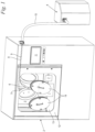
Fig. 1 zeigt in einer perspektivischen Ansicht ein erfindungsgemäß ausgeführtes Verarbeitungssystem für pharmazeutische Pulver. Das Verarbeitungssystem umfasst eine nur schematisch als Block angedeutete Verarbeitungsvorrichtung 1 für das Pulver, welche hier eine Kapselfülleinrichtung ist, aber auch eine Tablettenpresse oder dgl. sein kann. Des Weiteren umfasst das Verarbeitungssystem ein geschlossenes Gehäuse 2, welches einen inneren Produktionsraum 3 umschließt und diesen während des Betriebes hermetisch gegenüber der äußeren Umgebung abdichtet. Die Verarbeitungsvorrichtung 1 ist in diesem inneren Produktionsraum 3 platziert, so dass keine Teilmengen des zu verarbeitenden Pulvers nach außen gelangen können. - Eine Bedienung der Verarbeitungsvorrichtung 1 von der Außenseite des Gehäuses 2 aus ist mittels eines Nutzerinterfaces 11 möglich. Eine visuelle Überwachung des Betriebes kann durch ein Fenster 13 vorgenommen werden, welches zudem mit Handschuheingriffen 14 ausgestattet ist. Bei Bedarf kann ein manueller Zugriff über die Handschuheingriffe 14 erfolgen, ohne dass das Gehäuse 2 geöffnet werden muss. Im dekontaminierten Zustand kann das Gehäuse 2 jedoch geöffnet werden, wozu eine Tür 12 vorgesehen ist.
- Während des Betriebes der Verarbeitungsvorrichtung 1 können sich im inneren Produktionsraum 3 auf den Innenflächen des Gehäuses 2 sowie auf allen Oberflächen der Verarbeitungsvorrichtung 1 Pulverrückstände absetzen. Außerdem schweben in der Luft des Produktionsraumes 3 luftgetragene Pulverpartikel. All diese Pulverrückstände bzw. Pulverpartikel müssen bei Bedarf durch Reinigen entfernt werden. Hierzu umfasst das erfindungsgemäße Verarbeitungssystem neben dem Gehäuse 2 und der im inneren Produktionsraum 3 angeordneten Verarbeitungsvorrichtung 1 zusätzlich noch einen Dampferzeuger 4. Der Dampferzeuger 4 ist als eigenständige Einheit separat vom Gehäuse 2 dargestellt, kann aber auch in das Gehäuse 2 bzw. in die Verarbeitungsvorrichtung 1 integriert sein. Eine Ansteuerung des Dampferzeugers 4 erfolgt über das Nutzerinterface 11. Der Dampferzeuger 4 ist über einen Medienschlauch 10 mit dem Gehäuse 2 verbunden. Im Betrieb, d. h. für den Zweck einer Dekontamination nach Produktionsende oder in einer Produktionspause, wird mittels des Dampferzeugers 4 heißer Wasserdampf, also Wasser in seiner gasförmigen Phase erzeugt und durch den Medienschlauch 10 in den Produktionsraum 3 eingeleitet. Der Dampferzeuger 4 ist hinsichtlich seiner Kapazität und Ansteuerung dazu ausgelegt, dass im Produktionsraum 3 mit Wasserdampf übersättigte Luft entsteht. Im entsprechenden Verfahrensschritt wird also Wasserdampf in einer solchen Menge in den Produktionsraum 3 eingeleitet, dass die ohnehin darin vorhandene Luft mit Wasserdampf übersättigt wird und folglich zu einem Aufkondensieren von Wasser führt. Das Kondensieren des Wassers erfolgt an allen freien Oberflächen im Produktionsraum 3, also als Nebeltröpfchen an frei in der Luftfüllung des Produktionsraumes schwebenden Pulverpartikeln, an den Innenflächen des Gehäuses 2 sowie an allen freien Oberflächen der Verarbeitungsvorrichtung 1. Dabei wird so lange Wasserdampf nachgeführt, bis alle Schwebeteilchen von Nebeltröpfchen erfasst und bis alle Oberflächen mit Kondenswasser in flüssiger Phase soweit benetzt sind, dass daran anhaftende Pulverrückstände durch das Wasser gebunden sind. Die Nebeltröpfchen mit den darin gebundenen Pulverpartikeln sedimentieren nach einer Weile, setzen sich also an den Innenflächen des Gehäuses 2 sowie an den freien Oberflächen der Verarbeitungsvorrichtung 1 ab.
- Nach erfolgter Kondensation und Sedimentierung, also nach Bindung der Pulverrückstände kann die Tür 12 geöffnet werden und eine Reinigung des Produktionsraumes 3 einschließlich der Verarbeitungsvorrichtung 1 erfolgen. Hierzu kann das Kondensat mit den darin gebundenen Pulverrückständen abgesaugt und/oder abgewischt werden.
- Die Einleitung des Wasserdampfes in den Produktionsraum 3 erfolgt im gezeigten Ausführungsbeispiel mittels einer ortsfesten, vom Dampferzeuger 4 durch eine Dampfleitung 8 gespeisten Dampfdüse. Der hierdurch eingespeiste Wasserdampf durchmischt sich mit der Luft, bis die gewünschte Übersättigung zumindest abschnittsweise, das heißt in zumindest allen relevanten Volumenbereichen erreicht ist. Zur Unterstützung des dann einsetzenden Kondensationsprozesses und der damit einhergehenden Feuchtigkeitsbenetzung der Oberflächen kann optional ein Ultraschallbefeuchter 7 eingesetzt werden, welcher hier nur in schematischer Blockdarstellung angedeutet und im Produktionsraum 3 positioniert ist. Der Ultraschallbefeuchter 7 kann aber auch an anderer geeigneter Stelle, beispielsweise im Gehäuse des Dampferzeugers 4 angeordnet sein. Jedenfalls können mittels des Ultraschallbefeuchters 7 bei Bedarf feine Wassertröpfchen erzeugt und in die Luftfüllung des Produktionsraumes 3 abgegeben werden. Auch diese Wassertröpfchen binden Schwebeteilchen, und auch sie setzen sich auf den freien Oberflächen ab und tragen zur Bindung von Pulverrückständen bei.
- Vor dem beschriebenen Prozess der Pulverbindung mittels kondensiertem Wasser kann optional eine Vorreinigung der Oberflächen bei geschlossenem Gehäuse 2 erfolgen. Hierzu ist optional eine Druckdüse 6 vorgesehen, welche durch einen flexiblen Schlauch gespeist ist und mittels der Handschuheingriffe 14 manuell geführt werden kann. Der Maschinenbediener kann hiermit die verschmutzten Oberflächen freiblasen, woraufhin dann die aufgewirbelten Pulvermengen abgesaugt werden. Die Druckdüse 6 kann beispielsweise eine Druckluftdüse oder eine Mehrstoffdüse zur Einspeisung eines Luft-Wasser-Gemisches sein. Im gezeigten Ausführungsbeispiel handelt es sich um eine Heißdampfdüse, welche durch eine Dampfleitung 9 vom Dampferzeuger 4 gespeist ist.
- Der mit Druck auf die entsprechenden Oberflächen auftreffende Heißdampf führt zunächst in vorstehend beschriebener Weise zu einer Vorreinigung. Darüber hinaus trägt er zur Erhöhung der relativen Luftfeuchte im Produktionsraum 3 bei. Dementsprechend muss anschließend nur noch eine geringere Menge von Wasserdampf durch die ortsfeste Dampfdüse 5 eingespeist werden, bis der Zustand der Übersättigung und Kondensation eintritt. Alternativ kann es auch ausreichen, auf die ortsfeste Dampfdüse 5 ganz zu verzichten und die Wasserdampfeinspeisung sowohl für die Vorreinigung als auch für die Erzeugung des übersättigten Kondensationszustandes allein mittels der Druckdüse 6 vorzunehmen.
Claims (8)
- Verarbeitungssystem für insbesondere pharmazeutische Pulver, umfassend eine Verarbeitungsvorrichtung (1) für das Pulver sowie ein geschlossenes Gehäuse (2) mit einem inneren Produktionsraum (3), wobei die Verarbeitungsvorrichtung (1) in dem vom Gehäuse (2) umschlossenen Produktionsraum (3) angeordnet ist, dadurch gekennzeichnet, dass das Verarbeitungssystem des Weiteren einen Dampferzeuger (4) umfasst, welcher dazu ausgelegt ist, Wasserdampf in den Produktionsraum (3) derart einzuleiten, dass dort zumindest abschnittsweise mit Wasserdampf übersättigte Luft entsteht.
- Verarbeitungssystem nach Anspruch 1,
dadurch gekennzeichnet, dass im Produktionsraum (3) eine ortsfeste, vom Dampferzeuger (4) gespeiste Dampfdüse (5) angeordnet ist. - Verarbeitungssystem nach Anspruch 1 oder 2,
dadurch gekennzeichnet, dass das Verarbeitungssystem eine manuell zu führende Druckdüse (6) umfasst. - Verarbeitungssystem nach Anspruch 3,
dadurch gekennzeichnet, dass die Druckdüse (6) vom Dampferzeuger (4) gespeist ist. - Verarbeitungssystem nach einem der Ansprüche 1 bis 4,
dadurch gekennzeichnet, dass das Verarbeitungssystem zusätzlich einen Ultraschallbefeuchter (7) zur Einleitung von Feuchtigkeit in den Produktionsraum (3) umfasst. - Verfahren zur Dekontamination eines Verarbeitungssystems nach einem der Ansprüche 1 bis 5, umfassend folgende Verfahrensschritte:- Bei geschlossenem Gehäuse (2) wird in den Produktionsraum (3) Wasserdampf in einer solchen Menge eingeleitet, dass dort zumindest abschnittsweise mit Wasserdampf übersättigte Luft entsteht.- Eventuell vorhandene Pulverrückstände werden mittels Wasser dadurch gebunden, dass infolge der Übersättigung Wasser im Produktionsraum (3) kondensiert.- Das kondensierte Wasser einschließlich darin gebundener Pulverrückstände wird bei insbesondere geöffnetem Gehäuse (2) entfernt.
- Verfahren nach Anspruch 6,
dadurch gekennzeichnet, dass bei geschlossenem Gehäuse (2) eine Vorreinigung mittels einer insbesondere vom Dampferzeuger (4) gespeisten Druckdüse (6) vorgenommen wird. - Verfahren nach Anspruch 6 oder 7,
dadurch gekennzeichnet, dass die durch kondensiertes Wasser hervorgerufene Bindung von Pulverrückständen mittels eines Ultraschallbefeuchters (7) unterstützt wird.
Priority Applications (4)
| Application Number | Priority Date | Filing Date | Title |
|---|---|---|---|
| EP19210187.1A EP3825017B1 (de) | 2019-11-19 | 2019-11-19 | Verarbeitungssystem für pulver und verfahren zur dekontamination eines solchen verarbeitungssystems |
| US16/951,791 US20210145748A1 (en) | 2019-11-19 | 2020-11-18 | Processing system for powders, and method for decontamination of such a processing system |
| CN202011300953.1A CN112902365A (zh) | 2019-11-19 | 2020-11-19 | 用于粉末的加工系统和用于净化这样的加工系统的方法 |
| CA3101565A CA3101565A1 (en) | 2019-11-19 | 2020-12-02 | Processing system for powders, and method for decontamination of such a processing system |
Applications Claiming Priority (1)
| Application Number | Priority Date | Filing Date | Title |
|---|---|---|---|
| EP19210187.1A EP3825017B1 (de) | 2019-11-19 | 2019-11-19 | Verarbeitungssystem für pulver und verfahren zur dekontamination eines solchen verarbeitungssystems |
Publications (2)
| Publication Number | Publication Date |
|---|---|
| EP3825017A1 EP3825017A1 (de) | 2021-05-26 |
| EP3825017B1 true EP3825017B1 (de) | 2023-07-26 |
Family
ID=68732672
Family Applications (1)
| Application Number | Title | Priority Date | Filing Date |
|---|---|---|---|
| EP19210187.1A Active EP3825017B1 (de) | 2019-11-19 | 2019-11-19 | Verarbeitungssystem für pulver und verfahren zur dekontamination eines solchen verarbeitungssystems |
Country Status (4)
| Country | Link |
|---|---|
| US (1) | US20210145748A1 (de) |
| EP (1) | EP3825017B1 (de) |
| CN (1) | CN112902365A (de) |
| CA (1) | CA3101565A1 (de) |
Families Citing this family (1)
| Publication number | Priority date | Publication date | Assignee | Title |
|---|---|---|---|---|
| CN113500054B (zh) * | 2021-07-15 | 2023-04-07 | 霍邱村夫水产养殖有限公司 | 一种可移动的小龙虾养殖用喷射型消毒装置 |
Family Cites Families (12)
| Publication number | Priority date | Publication date | Assignee | Title |
|---|---|---|---|---|
| CH300425A (de) * | 1951-08-01 | 1954-07-31 | Dole Eng Co James | Apparat zum Abfüllen eines Produktes in Behälter. |
| US5256208A (en) * | 1991-10-01 | 1993-10-26 | Rafson Harold J | Process for removing volatile contaminants from granular materials |
| US5356482A (en) * | 1991-12-10 | 1994-10-18 | Serv-Tech, Inc. | Process for vessel decontamination |
| DE19522525A1 (de) * | 1994-10-04 | 1996-04-11 | Kunze Concewitz Horst Dipl Phy | Verfahren und Vorrichtung zum Feinstreinigen von Oberflächen |
| DE69634765T2 (de) * | 1995-08-22 | 2005-11-17 | Venturedyne, Ltd., Milwaukee | Zytogenetische Kammer und Verfahren für seine Anwendung |
| CN1223606A (zh) * | 1996-04-24 | 1999-07-21 | 梅斯T·米亚萨基 | 用于清洁油槽及其它物体的内部的方法及装置 |
| ATE309053T1 (de) * | 1999-09-02 | 2005-11-15 | Boerger & Co Gmbh H | Pulverrückgewinnungseinheit |
| ATE372136T1 (de) * | 2002-03-28 | 2007-09-15 | Bioquell Uk Ltd | Verfahren und vorrichtung zur dekontamination von geschlossenen räumen |
| JP2005331862A (ja) * | 2004-05-21 | 2005-12-02 | Inst Of Research & Innovation | 顕微鏡観察用培養装置 |
| DE202006003844U1 (de) * | 2006-03-10 | 2006-05-04 | MAX-PLANCK-Gesellschaft zur Förderung der Wissenschaften e.V. | Klimakammer, insbesondere für molekularbiologische Anwendungen |
| EP2108464A1 (de) * | 2008-04-09 | 2009-10-14 | Dow Global Technologies Inc. | Verfahren zur Reinigung von Gegenstände |
| EP2883526B1 (de) * | 2013-12-11 | 2020-03-18 | Harro Höfliger Verpackungsmaschinen GmbH | Verarbeitungssystem für Pulver und Verfahren zur Verarbeitung von Pulver |
-
2019
- 2019-11-19 EP EP19210187.1A patent/EP3825017B1/de active Active
-
2020
- 2020-11-18 US US16/951,791 patent/US20210145748A1/en not_active Abandoned
- 2020-11-19 CN CN202011300953.1A patent/CN112902365A/zh active Pending
- 2020-12-02 CA CA3101565A patent/CA3101565A1/en active Pending
Also Published As
| Publication number | Publication date |
|---|---|
| US20210145748A1 (en) | 2021-05-20 |
| CA3101565A1 (en) | 2021-05-19 |
| EP3825017A1 (de) | 2021-05-26 |
| CN112902365A (zh) | 2021-06-04 |
Similar Documents
| Publication | Publication Date | Title |
|---|---|---|
| DE60306330T2 (de) | Verfahren zum anschliessen einer handhabungseinrichtung an eine hülle mit sterilem inhalt | |
| DE2725492A1 (de) | Lukenkonstruktion zur anbringung eines bedienungselements an einem abschirmgehaeuse | |
| WO2018072882A1 (de) | Reinigungs-, desinfektions- und trocknungs-anlage | |
| EP1354695B1 (de) | Verfahren zur umgebungsgeschützen Herstellung von Tabletten auf einer Tablettenpresse und Schutzeinrichtung | |
| EP2616383B1 (de) | Behälterbehandlungsvorrichtung mit multifunktionalem reinigungsroboter | |
| DE2847862C3 (de) | Kühleinrichtung zum Kühlen der Atmosphäre im Primärschutzbehälter eines Kernreaktors | |
| EP3825017A1 (de) | Verarbeitungssystem für pulver und verfahren zur dekontamination eines solchen verarbeitungssystems | |
| EP2335886B1 (de) | Anordnung zur Verarbeitung von kontaminationsgefährdenden Stoffen | |
| EP2883526B1 (de) | Verarbeitungssystem für Pulver und Verfahren zur Verarbeitung von Pulver | |
| DE102011054683A1 (de) | Trocknungsvorrichtung für Behälter und Verfahren zum Reinigen einer solchen Trocknungsvorrichtung | |
| DE4124595A1 (de) | Verfahren zum aufarbeiten von bildroehren aus fernsehgeraeten o. dgl. | |
| EP0462529B1 (de) | Verfahren und Vorrichtung zur Reinigung von kontaminierten Stoffen und Geräten | |
| EP0431335A2 (de) | Vorrichtung zum Entsorgen des Kältemittels von Absorptions-Kältesystemen | |
| DE2637559A1 (de) | Verfahren und vorrichtung zum austausch und zur abfallbeseitigung von in einem gehaeuse dichtend aufgenommenen schwebstoff-filterelementen fuer kerntechnische anlagen | |
| EP2802823A2 (de) | Verschliessbare filtereinheit für einen isolator oder reinraum und verfahren zum betrieb eines isolators oder reinraums | |
| DE10034269A1 (de) | Vorrichtung zur Reinigung von Müllbehältern | |
| DE4112914C2 (de) | Verfahren und Vorrichtung zum Regenerieren schadstoffbelasteter Teile | |
| DE4240387A1 (de) | Abtrennen organischer Verunreinigungen, insbesondere Öle, von Gegenständen wie Abfallprodukten | |
| DE102021000553A1 (de) | Verfahren und Vorrichtung zur Hygienisierung von Mehrwegbehältern, insbesondere kastenartigen Kunststoffmehrwegbehältern | |
| DE102016117703B4 (de) | Vorrichtung zur Behandlung von radioaktiv kontaminierten Abwässern | |
| DE102023116934A1 (de) | Rundläuferpresse und Verfahren zum Vorreinigen des Pressengehäuses einer Rundläuferpresse | |
| EP3749160B1 (de) | Partikelaufnahmeeinrichtung, anordnung und verfahren zum betreiben einer anordnung | |
| DE4330184A1 (de) | Verfahren zum Recycling einer Kathodenstrahlröhre | |
| DE4424531A1 (de) | Verfahren und Vorrichtung zum Entleeren eines mit einer Flüssigkeit gefüllten Behälters | |
| DE69905140T2 (de) | Vorrichtung und verfahren zur reinigung von werkstücken |
Legal Events
| Date | Code | Title | Description |
|---|---|---|---|
| PUAI | Public reference made under article 153(3) epc to a published international application that has entered the european phase |
Free format text: ORIGINAL CODE: 0009012 |
|
| STAA | Information on the status of an ep patent application or granted ep patent |
Free format text: STATUS: THE APPLICATION HAS BEEN PUBLISHED |
|
| AK | Designated contracting states |
Kind code of ref document: A1 Designated state(s): AL AT BE BG CH CY CZ DE DK EE ES FI FR GB GR HR HU IE IS IT LI LT LU LV MC MK MT NL NO PL PT RO RS SE SI SK SM TR |
|
| STAA | Information on the status of an ep patent application or granted ep patent |
Free format text: STATUS: REQUEST FOR EXAMINATION WAS MADE |
|
| 17P | Request for examination filed |
Effective date: 20211021 |
|
| RBV | Designated contracting states (corrected) |
Designated state(s): AL AT BE BG CH CY CZ DE DK EE ES FI FR GB GR HR HU IE IS IT LI LT LU LV MC MK MT NL NO PL PT RO RS SE SI SK SM TR |
|
| GRAP | Despatch of communication of intention to grant a patent |
Free format text: ORIGINAL CODE: EPIDOSNIGR1 |
|
| STAA | Information on the status of an ep patent application or granted ep patent |
Free format text: STATUS: GRANT OF PATENT IS INTENDED |
|
| RIC1 | Information provided on ipc code assigned before grant |
Ipc: B08B 15/02 20060101AFI20230314BHEP |
|
| INTG | Intention to grant announced |
Effective date: 20230404 |
|
| GRAS | Grant fee paid |
Free format text: ORIGINAL CODE: EPIDOSNIGR3 |
|
| GRAA | (expected) grant |
Free format text: ORIGINAL CODE: 0009210 |
|
| STAA | Information on the status of an ep patent application or granted ep patent |
Free format text: STATUS: THE PATENT HAS BEEN GRANTED |
|
| AK | Designated contracting states |
Kind code of ref document: B1 Designated state(s): AL AT BE BG CH CY CZ DE DK EE ES FI FR GB GR HR HU IE IS IT LI LT LU LV MC MK MT NL NO PL PT RO RS SE SI SK SM TR |
|
| REG | Reference to a national code |
Ref country code: CH Ref legal event code: EP |
|
| REG | Reference to a national code |
Ref country code: IE Ref legal event code: FG4D Free format text: LANGUAGE OF EP DOCUMENT: GERMAN |
|
| REG | Reference to a national code |
Ref country code: DE Ref legal event code: R096 Ref document number: 502019008638 Country of ref document: DE |
|
| REG | Reference to a national code |
Ref country code: LT Ref legal event code: MG9D |
|
| REG | Reference to a national code |
Ref country code: NL Ref legal event code: MP Effective date: 20230726 |
|
| PG25 | Lapsed in a contracting state [announced via postgrant information from national office to epo] |
Ref country code: NL Free format text: LAPSE BECAUSE OF FAILURE TO SUBMIT A TRANSLATION OF THE DESCRIPTION OR TO PAY THE FEE WITHIN THE PRESCRIBED TIME-LIMIT Effective date: 20230726 |
|
| PG25 | Lapsed in a contracting state [announced via postgrant information from national office to epo] |
Ref country code: GR Free format text: LAPSE BECAUSE OF FAILURE TO SUBMIT A TRANSLATION OF THE DESCRIPTION OR TO PAY THE FEE WITHIN THE PRESCRIBED TIME-LIMIT Effective date: 20231027 |
|
| PG25 | Lapsed in a contracting state [announced via postgrant information from national office to epo] |
Ref country code: IS Free format text: LAPSE BECAUSE OF FAILURE TO SUBMIT A TRANSLATION OF THE DESCRIPTION OR TO PAY THE FEE WITHIN THE PRESCRIBED TIME-LIMIT Effective date: 20231126 |
|
| PG25 | Lapsed in a contracting state [announced via postgrant information from national office to epo] |
Ref country code: SE Free format text: LAPSE BECAUSE OF FAILURE TO SUBMIT A TRANSLATION OF THE DESCRIPTION OR TO PAY THE FEE WITHIN THE PRESCRIBED TIME-LIMIT Effective date: 20230726 Ref country code: RS Free format text: LAPSE BECAUSE OF FAILURE TO SUBMIT A TRANSLATION OF THE DESCRIPTION OR TO PAY THE FEE WITHIN THE PRESCRIBED TIME-LIMIT Effective date: 20230726 Ref country code: PT Free format text: LAPSE BECAUSE OF FAILURE TO SUBMIT A TRANSLATION OF THE DESCRIPTION OR TO PAY THE FEE WITHIN THE PRESCRIBED TIME-LIMIT Effective date: 20231127 Ref country code: NO Free format text: LAPSE BECAUSE OF FAILURE TO SUBMIT A TRANSLATION OF THE DESCRIPTION OR TO PAY THE FEE WITHIN THE PRESCRIBED TIME-LIMIT Effective date: 20231026 Ref country code: LV Free format text: LAPSE BECAUSE OF FAILURE TO SUBMIT A TRANSLATION OF THE DESCRIPTION OR TO PAY THE FEE WITHIN THE PRESCRIBED TIME-LIMIT Effective date: 20230726 Ref country code: LT Free format text: LAPSE BECAUSE OF FAILURE TO SUBMIT A TRANSLATION OF THE DESCRIPTION OR TO PAY THE FEE WITHIN THE PRESCRIBED TIME-LIMIT Effective date: 20230726 Ref country code: IS Free format text: LAPSE BECAUSE OF FAILURE TO SUBMIT A TRANSLATION OF THE DESCRIPTION OR TO PAY THE FEE WITHIN THE PRESCRIBED TIME-LIMIT Effective date: 20231126 Ref country code: HR Free format text: LAPSE BECAUSE OF FAILURE TO SUBMIT A TRANSLATION OF THE DESCRIPTION OR TO PAY THE FEE WITHIN THE PRESCRIBED TIME-LIMIT Effective date: 20230726 Ref country code: GR Free format text: LAPSE BECAUSE OF FAILURE TO SUBMIT A TRANSLATION OF THE DESCRIPTION OR TO PAY THE FEE WITHIN THE PRESCRIBED TIME-LIMIT Effective date: 20231027 Ref country code: FI Free format text: LAPSE BECAUSE OF FAILURE TO SUBMIT A TRANSLATION OF THE DESCRIPTION OR TO PAY THE FEE WITHIN THE PRESCRIBED TIME-LIMIT Effective date: 20230726 |
|
| PG25 | Lapsed in a contracting state [announced via postgrant information from national office to epo] |
Ref country code: PL Free format text: LAPSE BECAUSE OF FAILURE TO SUBMIT A TRANSLATION OF THE DESCRIPTION OR TO PAY THE FEE WITHIN THE PRESCRIBED TIME-LIMIT Effective date: 20230726 |
|
| PG25 | Lapsed in a contracting state [announced via postgrant information from national office to epo] |
Ref country code: ES Free format text: LAPSE BECAUSE OF FAILURE TO SUBMIT A TRANSLATION OF THE DESCRIPTION OR TO PAY THE FEE WITHIN THE PRESCRIBED TIME-LIMIT Effective date: 20230726 |
|
| REG | Reference to a national code |
Ref country code: DE Ref legal event code: R097 Ref document number: 502019008638 Country of ref document: DE |
|
| PG25 | Lapsed in a contracting state [announced via postgrant information from national office to epo] |
Ref country code: SM Free format text: LAPSE BECAUSE OF FAILURE TO SUBMIT A TRANSLATION OF THE DESCRIPTION OR TO PAY THE FEE WITHIN THE PRESCRIBED TIME-LIMIT Effective date: 20230726 Ref country code: RO Free format text: LAPSE BECAUSE OF FAILURE TO SUBMIT A TRANSLATION OF THE DESCRIPTION OR TO PAY THE FEE WITHIN THE PRESCRIBED TIME-LIMIT Effective date: 20230726 Ref country code: ES Free format text: LAPSE BECAUSE OF FAILURE TO SUBMIT A TRANSLATION OF THE DESCRIPTION OR TO PAY THE FEE WITHIN THE PRESCRIBED TIME-LIMIT Effective date: 20230726 Ref country code: EE Free format text: LAPSE BECAUSE OF FAILURE TO SUBMIT A TRANSLATION OF THE DESCRIPTION OR TO PAY THE FEE WITHIN THE PRESCRIBED TIME-LIMIT Effective date: 20230726 Ref country code: DK Free format text: LAPSE BECAUSE OF FAILURE TO SUBMIT A TRANSLATION OF THE DESCRIPTION OR TO PAY THE FEE WITHIN THE PRESCRIBED TIME-LIMIT Effective date: 20230726 Ref country code: CZ Free format text: LAPSE BECAUSE OF FAILURE TO SUBMIT A TRANSLATION OF THE DESCRIPTION OR TO PAY THE FEE WITHIN THE PRESCRIBED TIME-LIMIT Effective date: 20230726 Ref country code: SK Free format text: LAPSE BECAUSE OF FAILURE TO SUBMIT A TRANSLATION OF THE DESCRIPTION OR TO PAY THE FEE WITHIN THE PRESCRIBED TIME-LIMIT Effective date: 20230726 |
|
| PLBE | No opposition filed within time limit |
Free format text: ORIGINAL CODE: 0009261 |
|
| STAA | Information on the status of an ep patent application or granted ep patent |
Free format text: STATUS: NO OPPOSITION FILED WITHIN TIME LIMIT |
|
| REG | Reference to a national code |
Ref country code: CH Ref legal event code: PL |
|
| PG25 | Lapsed in a contracting state [announced via postgrant information from national office to epo] |
Ref country code: MC Free format text: LAPSE BECAUSE OF FAILURE TO SUBMIT A TRANSLATION OF THE DESCRIPTION OR TO PAY THE FEE WITHIN THE PRESCRIBED TIME-LIMIT Effective date: 20230726 |
|
| 26N | No opposition filed |
Effective date: 20240429 |
|
| PG25 | Lapsed in a contracting state [announced via postgrant information from national office to epo] |
Ref country code: LU Free format text: LAPSE BECAUSE OF NON-PAYMENT OF DUE FEES Effective date: 20231119 |
|
| PG25 | Lapsed in a contracting state [announced via postgrant information from national office to epo] |
Ref country code: CH Free format text: LAPSE BECAUSE OF NON-PAYMENT OF DUE FEES Effective date: 20231130 |
|
| PG25 | Lapsed in a contracting state [announced via postgrant information from national office to epo] |
Ref country code: MC Free format text: LAPSE BECAUSE OF FAILURE TO SUBMIT A TRANSLATION OF THE DESCRIPTION OR TO PAY THE FEE WITHIN THE PRESCRIBED TIME-LIMIT Effective date: 20230726 Ref country code: LU Free format text: LAPSE BECAUSE OF NON-PAYMENT OF DUE FEES Effective date: 20231119 Ref country code: CH Free format text: LAPSE BECAUSE OF NON-PAYMENT OF DUE FEES Effective date: 20231130 Ref country code: SI Free format text: LAPSE BECAUSE OF FAILURE TO SUBMIT A TRANSLATION OF THE DESCRIPTION OR TO PAY THE FEE WITHIN THE PRESCRIBED TIME-LIMIT Effective date: 20230726 |
|
| REG | Reference to a national code |
Ref country code: BE Ref legal event code: MM Effective date: 20231130 |
|
| PG25 | Lapsed in a contracting state [announced via postgrant information from national office to epo] |
Ref country code: BE Free format text: LAPSE BECAUSE OF NON-PAYMENT OF DUE FEES Effective date: 20231130 |
|
| PG25 | Lapsed in a contracting state [announced via postgrant information from national office to epo] |
Ref country code: BE Free format text: LAPSE BECAUSE OF NON-PAYMENT OF DUE FEES Effective date: 20231130 |
|
| PG25 | Lapsed in a contracting state [announced via postgrant information from national office to epo] |
Ref country code: BG Free format text: LAPSE BECAUSE OF FAILURE TO SUBMIT A TRANSLATION OF THE DESCRIPTION OR TO PAY THE FEE WITHIN THE PRESCRIBED TIME-LIMIT Effective date: 20230726 |
|
| PG25 | Lapsed in a contracting state [announced via postgrant information from national office to epo] |
Ref country code: BG Free format text: LAPSE BECAUSE OF FAILURE TO SUBMIT A TRANSLATION OF THE DESCRIPTION OR TO PAY THE FEE WITHIN THE PRESCRIBED TIME-LIMIT Effective date: 20230726 |
|
| PG25 | Lapsed in a contracting state [announced via postgrant information from national office to epo] |
Ref country code: CY Free format text: LAPSE BECAUSE OF FAILURE TO SUBMIT A TRANSLATION OF THE DESCRIPTION OR TO PAY THE FEE WITHIN THE PRESCRIBED TIME-LIMIT; INVALID AB INITIO Effective date: 20191119 |
|
| PG25 | Lapsed in a contracting state [announced via postgrant information from national office to epo] |
Ref country code: HU Free format text: LAPSE BECAUSE OF FAILURE TO SUBMIT A TRANSLATION OF THE DESCRIPTION OR TO PAY THE FEE WITHIN THE PRESCRIBED TIME-LIMIT; INVALID AB INITIO Effective date: 20191119 |
|
| PGFP | Annual fee paid to national office [announced via postgrant information from national office to epo] |
Ref country code: DE Payment date: 20251119 Year of fee payment: 7 |
|
| PGFP | Annual fee paid to national office [announced via postgrant information from national office to epo] |
Ref country code: GB Payment date: 20251121 Year of fee payment: 7 |
|
| PG25 | Lapsed in a contracting state [announced via postgrant information from national office to epo] |
Ref country code: AT Free format text: LAPSE BECAUSE OF NON-PAYMENT OF DUE FEES Effective date: 20241119 |
|
| PGFP | Annual fee paid to national office [announced via postgrant information from national office to epo] |
Ref country code: IT Payment date: 20251125 Year of fee payment: 7 |
|
| PGFP | Annual fee paid to national office [announced via postgrant information from national office to epo] |
Ref country code: FR Payment date: 20251126 Year of fee payment: 7 |
|
| REG | Reference to a national code |
Ref country code: AT Ref legal event code: MM01 Ref document number: 1591342 Country of ref document: AT Kind code of ref document: T Effective date: 20241119 |
|
| PGFP | Annual fee paid to national office [announced via postgrant information from national office to epo] |
Ref country code: TR Payment date: 20251112 Year of fee payment: 7 |
|
| PGFP | Annual fee paid to national office [announced via postgrant information from national office to epo] |
Ref country code: IE Payment date: 20251121 Year of fee payment: 7 |
|
| PGFP | Annual fee paid to national office [announced via postgrant information from national office to epo] |
Ref country code: AT Payment date: 20260410 Year of fee payment: 5 |