EP3822069A1 - Presse à balles - Google Patents
Presse à balles Download PDFInfo
- Publication number
- EP3822069A1 EP3822069A1 EP19209310.2A EP19209310A EP3822069A1 EP 3822069 A1 EP3822069 A1 EP 3822069A1 EP 19209310 A EP19209310 A EP 19209310A EP 3822069 A1 EP3822069 A1 EP 3822069A1
- Authority
- EP
- European Patent Office
- Prior art keywords
- ram
- press
- baling press
- press ram
- gripping hook
- Prior art date
- Legal status (The legal status is an assumption and is not a legal conclusion. Google has not performed a legal analysis and makes no representation as to the accuracy of the status listed.)
- Withdrawn
Links
Images


Classifications
-
- B—PERFORMING OPERATIONS; TRANSPORTING
- B30—PRESSES
- B30B—PRESSES IN GENERAL
- B30B9/00—Presses specially adapted for particular purposes
- B30B9/30—Presses specially adapted for particular purposes for baling; Compression boxes therefor
- B30B9/3003—Details
- B30B9/3007—Control arrangements
-
- B—PERFORMING OPERATIONS; TRANSPORTING
- B30—PRESSES
- B30B—PRESSES IN GENERAL
- B30B9/00—Presses specially adapted for particular purposes
- B30B9/30—Presses specially adapted for particular purposes for baling; Compression boxes therefor
- B30B9/3003—Details
- B30B9/3021—Press rams
Definitions
- the invention relates to a baling press by means of which isolated objects, for example cardboard boxes, paper, leaves, grass or the like are pressed into a bale strapped with a wire, according to the preamble of claim 1.
- baling presses have been in use for decades, especially in grocery stores, because they produce enormous amounts of voluminous cardboard packaging, which are pressed into a cuboidal bale by such baling presses.
- they are strapped with a wire.
- the bale can be strapped by means of a wire loop. This can, for example, from the EP 3 199 331 A1 can be removed.
- the baling presses can be arranged in a vertical, horizontal or inclined position to these directions.
- the press channel is usually completely enclosed by means of four side walls as part of the housing, a door mounted pivotably on the housing of the baling press, and the press ram. Since the door can be moved into an open position, the press channel is accessible from the outside, so that the separated objects can be filled or pushed into the press channel.
- the ram is in its upper starting position and accordingly releases the entire circumference of the press channel and completely releases the opening to be closed by the door.
- the separated objects are filled in through a shaft which opens into the press channel. Accordingly, several pressing processes can be carried out and after each pressing process the volume of the bale can be increased by adding further objects.
- baler can also lead to personal injury, namely if the press channel is open during the lifting process of the press ram.
- At least one securing device is attached or provided on the respective press ram, that a holding device interacting with the securing device is arranged on or in at least one side wall of the housing and that the securing device is mechanically, depending on the position of the press ram and / or its speed, is activated hydraulically and / or electrically, in such a way that the securing device comes into operative contact with the holding device in a non-positive or form-fitting manner and the respective press ram is thereby held in a position-oriented manner through the operative contact established between the securing device and the holding device
- the press ram in its starting position, ie in the upper part, especially in vertically aligned balers, is permanently fixed by the securing device on the holding device, so that even in the event of material fatigue or material damage on the press ram and / or the drive device, the press ram and the drive device on the housing are held in a position-oriented manner and, on the other hand, it is ensured that if the door is
- the non-positive or form-fitting operative connection between the securing device attached to the ram and the holding device assigned to the housing means that reliable and permanent fixation is independent accessible from the state of motion of the ram.
- a control of the baling press regulating the stroke cycle of the press ram receives corresponding electrical signals through existing sensors attached to the door, which trigger the safety device so that it comes into operative contact with the holding device.
- the safety device is formed from a gripping hook which is rotatably leaned against the press ram by means of a hinge or swivel joint and if a compression spring, which preferably runs perpendicular to the direction of movement of the press ram, is arranged on this and the press channel, and if the slopes of the receiving opening of the gripping hook are appropriately aligned on the outside and inside, then the lifting force of the ram can automatically release or latch the gripping hook onto the bolt of the holding device without the need for additional sensors or other control measures.
- the slope of the receiving opening inside and outside is inclined from the vertical in such a way that the lifting force of the press ram overcomes the compressive force of the compression spring, so that the gripping hook is moved away from the bolt of the holding device against the force of the printing errors and consequently releases the movement of the press ram or, conversely, the gripping hook snaps the retaining bolt back into the securing position after the bolt has been driven over by the force of the printing error.
- the gripping hook partially encloses the bolt of the holding device in the manner of an undercut when the press ram is arranged in the starting position.
- the control of the baling press with additional electrical, magnetic, inductively operated or other sensors or actuators through which the direction of movement, the speed of movement and the position of the press ram are permanently recorded.
- the control can immediately switch off the drive device and activate the safety device so that it is in a force-fitting or form-fitting operative connection with the holding device is convicted.
- the brake can be designed as a rubber ring, which engages around a rod aligned parallel to the direction of movement of the press ram and as soon as the press ram is to be fixed, the brake is transferred from a horizontal position, i.e. perpendicular to the rod, into a deflection that runs obliquely to it, whereby the opening width the brake is reduced so that the frictional braking function takes place.
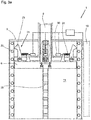
- a baling press 1 can be seen, by means of which isolated objects 2, for example cardboard boxes, paper, leaves, grass or the like are pressed into a bale 3 strapped with a wire 4.
- the separated objects 2 should accordingly be compressed by the baling press 1 in order to reduce the transport and storage costs of such voluminous separated objects 2 or to be able to handle them optimally.
- Such baling presses 1 are often set up in grocery stores where a large number of such items 2 are to be processed.
- the baler 1 consists of a housing 5 with four side walls 12, 13, 14 and 15, one of the side walls 13 representing the bottom of the housing 5.
- the illustrated embodiment of the baling press 1 is a so-called vertically aligned baling press 1. This means that the bottom 13 of the baling press 1 runs directly in the area and parallel to the ground.
- a press channel 11 is accordingly enclosed by the side walls 12, 13, 14, 15 as well as an axially movable press ram 6 arranged between them and a pivotably hinged door 16 on the housing 5.
- the separated objects 2 are poured into the press channel 11 through the opened door 16. It is also possible to provide a shaft, not shown, which opens into the press channel 11.
- the separated objects 2 can be filled in through the shaft as a function of the position of the press ram 6.
- the press ram 6 is connected to a drive device 8 in the form of a hydraulic piston, so that the press ram 6 can be moved in a stroke by the drive device 8 from an initial position 9 to an end position 10.
- the separated objects 2 are arranged between the press ram 6 and the bottom 13 of the housing 5, so that the objects 2 are pressed into a cuboid bale 3 by the lifting force of the press ram 6 applied by the drive device 8.
- this can be strapped by a wire 4 so that the bale 3 retains its fixed shape and can be removed from the press channel 11 through the open door 16.
- the press channel 11 In the open state of the door 16, the press channel 11 is accordingly accessible in order to introduce the objects 2 into it.
- the press channel 11 has dimensions which are dimensioned in such a way that people can fully or at least partially enter or reach into the press channel 11. Should material fatigue or material damage occur on the press ram 6 and / or the drive device 8 in this unactuated state of the press ram 6, these heavy components 6, 8 fall due to the prevailing gravity in the direction of the side wall 13 or the subsurface. Such movements lead to injuries or can even kill people.
- At least one safety device 21 is provided on the respective press ram 6 and at least one holding device 22 is provided on the housing 5, which are in force-fitting or form-fitting operative contact or are transferred to the press ram 6 and the drive device 8 lock in the starting position 9. If the ram 6 and the drive device 8 are fixed by the operative contact between the securing device 21 and the holding device 22, these heavy components 6, 8 cannot move due to the prevailing force of gravity and consequently people can enter the pressing channel 11 or reach into it without that it is to be feared that falling components 6,8 will result in injuries or even deaths.
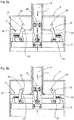
- the securing device 21 consists of a gripping hook 23 which is pivotably mounted on the upper side of the ram 6 by means of a hinge 26 in the form of a swivel joint. Between the hinge 26 and a gripping opening 27 assigned to the gripping hook 23, a compression spring 24 is arranged, which is oriented perpendicular to the direction of movement 7 of the ram 6.
- the gripping opening 27 has an inner contour 28 and an outer contour 29.
- the inner contour 28 is assigned to a bolt 25 which essentially the holding device 22 forms.
- the gripping opening 27 consequently partially encloses the bolt 25 in the manner of an undercut, so that a form-fitting operative connection is formed between the gripping hook 23 and the bolt 25.
- the compression spring 24 exerts a permanent holding force on the gripping hook 23 so that it is not released from the bolt 25 without additional forces acting.
- the inner contour 28 of the gripping opening 27 consists of a linear abutment structure which has an incline extending inclined from the vertical.
- the arrangement of the slope of the inner contour 28 is selected such that the holding force generated by the compression spring 24 is overcome by the lifting force applied by the drive device 8.
- the gripping hook 23 snaps against the force of the compression spring 24 from the bolt 25 and the ram 6 moves due to the prevailing force of the drive device 8 in the direction of the side wall 13 or the objects 2 and compresses them.
- the gripping hooks 23 and the respective bolts 25 are therefore released from one another and do not work together.
- the outer contour 29 of the gripping hook 23 arrives in accordance with FIG Figure 2b in operative contact with the bolt 25.
- the slope of the outer contour 29 is aligned in such a way that the lifting force exerted by the drive device 8 exerts a pivoting movement through the bolt 25 onto the gripping hook 23, whereby the compression spring 24 is compressed.
- the outer contour 29 accordingly slides along the bolt 25 until the end of the outer contour 29 is reached.
- the compression spring 24 presses the gripping hook 23 into the locking position according to FIG Figure 1 , whereby the ram 6 is locked in its initial state 9 on the housing 5.
- FIG. 3a and 3b is a development of the exemplary embodiments according to FIG Figures 2a and 2b can be seen, which consists in the fact that in the direction of the lifting movement 7 of the ram 6 a plurality of bolts 25 on the housing 5 are provided. The row of bolts 25 accordingly form different locking positions.
- Sensors 18, by means of which the position of the door 16 is permanently detected, are provided on the door 16.
- a control 17 of the baling press 1 is assigned to actuate the press ram 6 or the drive device 8.
- the sensors 18 are coupled to the controller 17.
- the controller 17 triggers the safety device 21; for this purpose, the compression spring 24 is assigned an actuator 30 that is electrically connected to the controller 17.
- the gripping hook 23 is accordingly transferred from a position deflected parallel to the side walls 12, 14, 15 into a locking position, because the compression spring 24 immediately exerts a corresponding movement force on the gripping hook 23, so that it is deflected in the direction of the closest bolt 25. Since a large number of such bolts 25 are assigned to the respective side walls 12, 14, 15, the gripping hook 23 snaps into one of the bolts 25 as soon as its design state is reached.
- sensors 19 can be assigned to the ram 6 or the drive device 8, by means of which the material condition is detected. If the sensors 19 detect damage, for example in the form of hairline cracks or the like, the ram 6 can be fixed immediately - as explained above.
- the Figures 1 to 3b Positive active connections in the manner of an undercut between the gripping hook 23 and the bolt 25 can be found. It is easily conceivable to have such form-fitting operative connections to replace frictional active connections in the form of brakes or hoop clutches.
- the gripping hook 23 can be designed as a rubber tire which grips or loops around a rod firmly connected to the housing 5 as a holding device 22. As soon as the control 17 detects an open door 16 or the ram 6 is to be fixed in the starting position 9, the brake can be tilted so that its opening width is reduced and the brake is applied to the rod.
- the actuator 30 can be designed as a magnet or an electrically operated sensor, so that small electrical pulses are sufficient to activate the compression spring 24.
- the controller 17 receives a corresponding signal from the sensors 18, whereby the actuator 30 is deactivated and the respective gripping hooks 23 are swiveled back into the starting position by the printing errors 24, that is again stand perpendicular or parallel to the side walls.
Landscapes
- Engineering & Computer Science (AREA)
- Mechanical Engineering (AREA)
- Press Drives And Press Lines (AREA)
Priority Applications (1)
| Application Number | Priority Date | Filing Date | Title |
|---|---|---|---|
| EP19209310.2A EP3822069A1 (fr) | 2019-11-15 | 2019-11-15 | Presse à balles |
Applications Claiming Priority (1)
| Application Number | Priority Date | Filing Date | Title |
|---|---|---|---|
| EP19209310.2A EP3822069A1 (fr) | 2019-11-15 | 2019-11-15 | Presse à balles |
Publications (1)
| Publication Number | Publication Date |
|---|---|
| EP3822069A1 true EP3822069A1 (fr) | 2021-05-19 |
Family
ID=68699138
Family Applications (1)
| Application Number | Title | Priority Date | Filing Date |
|---|---|---|---|
| EP19209310.2A Withdrawn EP3822069A1 (fr) | 2019-11-15 | 2019-11-15 | Presse à balles |
Country Status (1)
| Country | Link |
|---|---|
| EP (1) | EP3822069A1 (fr) |
Citations (7)
| Publication number | Priority date | Publication date | Assignee | Title |
|---|---|---|---|---|
| US4080889A (en) * | 1976-06-16 | 1978-03-28 | Mordechay Shiloni | Device for compacting trash and the like |
| JPH09141500A (ja) * | 1995-11-15 | 1997-06-03 | Asahi Tec Corp | プラテン用落下防止装置 |
| WO2009133581A1 (fr) * | 2008-04-28 | 2009-11-05 | Gauss Automazione S.P.A. | Dispositif antichute en particulier pour presses hydrauliques |
| CN102431208A (zh) * | 2011-09-20 | 2012-05-02 | 奇瑞汽车股份有限公司 | 一种压力机滑块锁紧机构 |
| CN202965272U (zh) * | 2012-11-26 | 2013-06-05 | 中信重工机械股份有限公司 | 一种液压机动梁自锁悬停装置 |
| EP3199331A1 (fr) | 2016-01-26 | 2017-08-02 | Maschinenfabrik Bermatingen GmbH & Co. KG | Presse à balles |
| CN110154435A (zh) * | 2019-05-16 | 2019-08-23 | 中信戴卡股份有限公司 | 一种铝屑压块装置 |
-
2019
- 2019-11-15 EP EP19209310.2A patent/EP3822069A1/fr not_active Withdrawn
Patent Citations (7)
| Publication number | Priority date | Publication date | Assignee | Title |
|---|---|---|---|---|
| US4080889A (en) * | 1976-06-16 | 1978-03-28 | Mordechay Shiloni | Device for compacting trash and the like |
| JPH09141500A (ja) * | 1995-11-15 | 1997-06-03 | Asahi Tec Corp | プラテン用落下防止装置 |
| WO2009133581A1 (fr) * | 2008-04-28 | 2009-11-05 | Gauss Automazione S.P.A. | Dispositif antichute en particulier pour presses hydrauliques |
| CN102431208A (zh) * | 2011-09-20 | 2012-05-02 | 奇瑞汽车股份有限公司 | 一种压力机滑块锁紧机构 |
| CN202965272U (zh) * | 2012-11-26 | 2013-06-05 | 中信重工机械股份有限公司 | 一种液压机动梁自锁悬停装置 |
| EP3199331A1 (fr) | 2016-01-26 | 2017-08-02 | Maschinenfabrik Bermatingen GmbH & Co. KG | Presse à balles |
| CN110154435A (zh) * | 2019-05-16 | 2019-08-23 | 中信戴卡股份有限公司 | 一种铝屑压块装置 |
Similar Documents
| Publication | Publication Date | Title |
|---|---|---|
| DE3036533C2 (de) | Hydraulische Pulverpresse | |
| DE202007018801U1 (de) | Vorrichtung zum Verpacken von Reifen | |
| DE3500056C2 (fr) | ||
| EP2597064B1 (fr) | Benne polype pour marchandises de stockage en pièces | |
| EP2283999A2 (fr) | Presse à balles | |
| EP3822069A1 (fr) | Presse à balles | |
| DE950183C (de) | Hydraulische Hubvorrichtung, insbesondere zum Setzen von Grubenstempeln | |
| DE2749486C2 (fr) | ||
| WO2004041523A1 (fr) | Presse a balles | |
| DE1756464A1 (de) | Greiferklemme zum Anheben von Stahlplatten od.dgl. | |
| EP2948400A1 (fr) | Dispositif d'interception intégré sur dispositifs de freinage d'envoi aux molettes | |
| EP1446998B1 (fr) | Dispositif pour assister la sortie d'une balle ronde | |
| DE1025336B (de) | Greifer fuer Hubgeraete zum Fassen und Halten stehender Faesser | |
| DE2718434B1 (de) | Am Ausleger einer Arbeitsmaschine angelegter Greifer | |
| EP3453529B1 (fr) | Presse à coffre à balles pourvue de porte coulissante ainsi que procédé de fonctionnement d'une presse à coffre | |
| EP4015207A1 (fr) | Presse à balles | |
| DE2626077C2 (de) | An einem Seil o.dgl. hängender Greifer | |
| DE1900188C3 (de) | Schutzvorrichtung an Mehrstufen pressen | |
| AT509503B1 (de) | Greifvorrichtung | |
| DE2152756A1 (de) | Vorrichtung zum Zerlegen von Faser materialballen in getrennte Schichten | |
| DE2143334A1 (de) | Muellpresse | |
| DE3937245C2 (de) | Schienenhaken | |
| DE2524622A1 (de) | Geraet zum entleeren oben offener behaelter, insbesondere von sinkschachteimern | |
| DE1531205C3 (de) | Greifer für Rundholzblöcke od. dgl | |
| DE1431207C (de) | Vorrichtung zur Aufnahme und Abgabe von Lasten mittels eines Luftfahrzeuges |
Legal Events
| Date | Code | Title | Description |
|---|---|---|---|
| PUAI | Public reference made under article 153(3) epc to a published international application that has entered the european phase |
Free format text: ORIGINAL CODE: 0009012 |
|
| STAA | Information on the status of an ep patent application or granted ep patent |
Free format text: STATUS: THE APPLICATION HAS BEEN PUBLISHED |
|
| AK | Designated contracting states |
Kind code of ref document: A1 Designated state(s): AL AT BE BG CH CY CZ DE DK EE ES FI FR GB GR HR HU IE IS IT LI LT LU LV MC MK MT NL NO PL PT RO RS SE SI SK SM TR |
|
| STAA | Information on the status of an ep patent application or granted ep patent |
Free format text: STATUS: THE APPLICATION IS DEEMED TO BE WITHDRAWN |
|
| 18D | Application deemed to be withdrawn |
Effective date: 20211120 |