EP3797744A1 - Dressing with contracting layer for linear tissue sites - Google Patents
Dressing with contracting layer for linear tissue sites Download PDFInfo
- Publication number
- EP3797744A1 EP3797744A1 EP20202628.2A EP20202628A EP3797744A1 EP 3797744 A1 EP3797744 A1 EP 3797744A1 EP 20202628 A EP20202628 A EP 20202628A EP 3797744 A1 EP3797744 A1 EP 3797744A1
- Authority
- EP
- European Patent Office
- Prior art keywords
- contracting layer
- holes
- dressing
- contracting
- hole
- Prior art date
- Legal status (The legal status is an assumption and is not a legal conclusion. Google has not performed a legal analysis and makes no representation as to the accuracy of the status listed.)
- Pending
Links
Images


Classifications
-
- A—HUMAN NECESSITIES
- A61—MEDICAL OR VETERINARY SCIENCE; HYGIENE
- A61F—FILTERS IMPLANTABLE INTO BLOOD VESSELS; PROSTHESES; DEVICES PROVIDING PATENCY TO, OR PREVENTING COLLAPSING OF, TUBULAR STRUCTURES OF THE BODY, e.g. STENTS; ORTHOPAEDIC, NURSING OR CONTRACEPTIVE DEVICES; FOMENTATION; TREATMENT OR PROTECTION OF EYES OR EARS; BANDAGES, DRESSINGS OR ABSORBENT PADS; FIRST-AID KITS
- A61F13/00—Bandages or dressings; Absorbent pads
- A61F13/05—Bandages or dressings; Absorbent pads specially adapted for use with sub-pressure or over-pressure therapy, wound drainage or wound irrigation, e.g. for use with negative-pressure wound therapy [NPWT]
-
- A—HUMAN NECESSITIES
- A61—MEDICAL OR VETERINARY SCIENCE; HYGIENE
- A61F—FILTERS IMPLANTABLE INTO BLOOD VESSELS; PROSTHESES; DEVICES PROVIDING PATENCY TO, OR PREVENTING COLLAPSING OF, TUBULAR STRUCTURES OF THE BODY, e.g. STENTS; ORTHOPAEDIC, NURSING OR CONTRACEPTIVE DEVICES; FOMENTATION; TREATMENT OR PROTECTION OF EYES OR EARS; BANDAGES, DRESSINGS OR ABSORBENT PADS; FIRST-AID KITS
- A61F13/00—Bandages or dressings; Absorbent pads
- A61F13/01—Non-adhesive bandages or dressings
- A61F13/01008—Non-adhesive bandages or dressings characterised by the material
- A61F13/01017—Non-adhesive bandages or dressings characterised by the material synthetic, e.g. polymer based
-
- A—HUMAN NECESSITIES
- A61—MEDICAL OR VETERINARY SCIENCE; HYGIENE
- A61F—FILTERS IMPLANTABLE INTO BLOOD VESSELS; PROSTHESES; DEVICES PROVIDING PATENCY TO, OR PREVENTING COLLAPSING OF, TUBULAR STRUCTURES OF THE BODY, e.g. STENTS; ORTHOPAEDIC, NURSING OR CONTRACEPTIVE DEVICES; FOMENTATION; TREATMENT OR PROTECTION OF EYES OR EARS; BANDAGES, DRESSINGS OR ABSORBENT PADS; FIRST-AID KITS
- A61F13/00—Bandages or dressings; Absorbent pads
- A61F13/01—Non-adhesive bandages or dressings
- A61F13/01034—Non-adhesive bandages or dressings characterised by a property
- A61F13/01042—Absorbency
-
- A—HUMAN NECESSITIES
- A61—MEDICAL OR VETERINARY SCIENCE; HYGIENE
- A61M—DEVICES FOR INTRODUCING MEDIA INTO, OR ONTO, THE BODY; DEVICES FOR TRANSDUCING BODY MEDIA OR FOR TAKING MEDIA FROM THE BODY; DEVICES FOR PRODUCING OR ENDING SLEEP OR STUPOR
- A61M1/00—Suction or pumping devices for medical purposes; Devices for carrying-off, for treatment of, or for carrying-over, body-liquids; Drainage systems
- A61M1/90—Negative pressure wound therapy devices, i.e. devices for applying suction to a wound to promote healing, e.g. including a vacuum dressing
- A61M1/91—Suction aspects of the dressing
- A61M1/915—Constructional details of the pressure distribution manifold
-
- A—HUMAN NECESSITIES
- A61—MEDICAL OR VETERINARY SCIENCE; HYGIENE
- A61M—DEVICES FOR INTRODUCING MEDIA INTO, OR ONTO, THE BODY; DEVICES FOR TRANSDUCING BODY MEDIA OR FOR TAKING MEDIA FROM THE BODY; DEVICES FOR PRODUCING OR ENDING SLEEP OR STUPOR
- A61M1/00—Suction or pumping devices for medical purposes; Devices for carrying-off, for treatment of, or for carrying-over, body-liquids; Drainage systems
- A61M1/90—Negative pressure wound therapy devices, i.e. devices for applying suction to a wound to promote healing, e.g. including a vacuum dressing
- A61M1/92—Negative pressure wound therapy devices, i.e. devices for applying suction to a wound to promote healing, e.g. including a vacuum dressing with liquid supply means
-
- A—HUMAN NECESSITIES
- A61—MEDICAL OR VETERINARY SCIENCE; HYGIENE
- A61M—DEVICES FOR INTRODUCING MEDIA INTO, OR ONTO, THE BODY; DEVICES FOR TRANSDUCING BODY MEDIA OR FOR TAKING MEDIA FROM THE BODY; DEVICES FOR PRODUCING OR ENDING SLEEP OR STUPOR
- A61M1/00—Suction or pumping devices for medical purposes; Devices for carrying-off, for treatment of, or for carrying-over, body-liquids; Drainage systems
- A61M1/90—Negative pressure wound therapy devices, i.e. devices for applying suction to a wound to promote healing, e.g. including a vacuum dressing
- A61M1/94—Negative pressure wound therapy devices, i.e. devices for applying suction to a wound to promote healing, e.g. including a vacuum dressing with gas supply means
Definitions
- the invention set forth in the appended claims relates generally to tissue treatment systems and more particularly, but without limitation, to a dressing having a contracting layer for assisting in closure of linear tissue sites.
- Negative-pressure therapy may provide a number of benefits, including migration of epithelial and subcutaneous tissues, improved blood flow, and micro-deformation of tissue at a wound site. Together, these benefits can increase development of granulation tissue and reduce healing times.
- a system for closing an opening through a surface of a tissue site may include a sealing member adapted to cover the opening to form a sealed space and a negative-pressure source adapted to be fluidly coupled to the sealed space to provide negative pressure to the sealed space.
- the system can include a protective layer adapted to be positioned adjacent to the opening.
- the system may also include a contracting layer adapted to be positioned adjacent to the protective layer and formed from a material having a firmness factor and a plurality of holes extending through the contracting layer to form a void space.
- the holes may have a perforation shape factor and a strut angle causing the plurality of holes to collapse in a direction substantially perpendicular to the opening.
- the contracting layer may generate a closing force substantially parallel to the surface of the tissue site to close the opening in response to application of the negative pressure.
- other example embodiments may include an apparatus for closing an opening through a surface of a tissue site.
- the apparatus may include a contracting layer adapted to be positioned adjacent the opening and formed from a material having a firmness factor and a plurality of holes extending through the contracting layer to form a void space.
- the holes may have a perforation shape factor and a strut angle causing the plurality of holes to collapse in a direction substantially perpendicular to the opening.
- the contracting layer may generate a closing force substantially parallel to the surface of the tissue site to close the opening in response to application of a negative pressure.
- a method for closing an opening through a surface of a tissue site may include positioning a contracting layer adjacent to and covering the tissue site.
- the contracting layer may be adapted to be positioned adjacent the opening and formed from a material having a firmness factor and a plurality of holes extending through the contracting layer to form a void space.
- the holes may have a perforation shape factor and a strut angle causing the plurality of holes to collapse in a direction substantially perpendicular to the opening.
- the contracting layer may be collapsed parallel to the surface of the tissue site to generate a closing force.
- FIG. 1 illustrates details that may be associated with some embodiments of a negative-pressure therapy system 100 that can be applied to a tissue site 102.
- the tissue site 102 may be closed by one or more stitches 103.
- the negative-pressure therapy system 100 may include a dressing and a negative-pressure source.
- a dressing 104 may be fluidly coupled to a negative-pressure source 106, as illustrated in Figure 1 .
- a dressing may be fluidly coupled to a negative-pressure source by a connector and a tube.
- the dressing 104 for example, may be fluidly coupled to the negative-pressure source 106 by a connector 108 and a tube 110.
- a dressing may generally include a cover and a tissue interface.
- the dressing 104 may include a cover 112 and a tissue interface 113.
- the tissue interface 113 may include a contracting layer, such as a contracting layer 114, and a protective layer, such as a protective layer 116.
- components of the negative-pressure therapy system 100 may be coupled directly or indirectly.
- the negative-pressure source 106 may be directly coupled to the dressing 104 and indirectly coupled to the tissue site 102 through the dressing 104.
- Components may be fluidly coupled to each other to provide a path for transferring fluids (i.e., liquid and/or gas) between the components.
- components may be fluidly coupled through a tube, such as the tube 110.
- a tube is an elongated, cylindrical structure with some flexibility, but the geometry and rigidity may vary.
- components may additionally or alternatively be coupled by virtue of physical proximity, being integral to a single structure, or being formed from the same piece of material. Coupling may also include mechanical, thermal, electrical, or chemical coupling (such as a chemical bond) in some contexts.
- a tissue interface such as the tissue interface 113
- a cover may be placed over a tissue interface and sealed to tissue near a tissue site.
- the tissue interface 113 may be placed over the tissue site 102, and the cover 112 may be sealed to undamaged epidermis peripheral to the tissue site 102.
- the cover 112 can provide a sealed therapeutic environment 118 proximate to the tissue site 102 that is substantially isolated from the external environment, and the negative-pressure source 106 can reduce the pressure in the sealed therapeutic environment 118.
- the fluid mechanics of using a negative-pressure source to reduce pressure in another component or location, such as within a sealed therapeutic environment, can be mathematically complex.
- the basic principles of fluid mechanics applicable to negative-pressure therapy are generally well-known to those skilled in the art, and the process of reducing pressure may be described illustratively herein as "delivering,” “distributing,” or “generating” negative pressure, for example.
- downstream typically refers to a position in a fluid path relatively closer to a negative-pressure source.
- upstream refers to a position relatively further away from a negative-pressure source.
- tissue site in this context broadly refers to a wound or a defect located on or within tissue, including but not limited to, bone tissue, adipose tissue, muscle tissue, neural tissue, dermal tissue, vascular tissue, connective tissue, cartilage, tendons, or ligaments.
- a wound may include chronic, acute, traumatic, subacute, and dehisced wounds, partial-thickness burns, ulcers (such as diabetic, pressure, or venous insufficiency ulcers), flaps, and grafts, for example.
- tissue site may also refer to areas of any tissue that are not necessarily wounded or defective, but are instead areas in which it may be desirable to add or promote the growth of additional tissue. For example, negative pressure may be used at a tissue site to grow additional tissue that may be harvested and transplanted to a tissue site at another location.
- a tissue site may also be characterized by shape.
- tissue sites may be referred to as a linear tissue site.
- a linear tissue site may generally refer to a tissue site having an elongated shape, such as an incision having a length substantially greater than its width.
- An incision may have edges that may be substantially parallel, particularly if the incision is caused by a scalpel, knife, razor, or other sharp blade.
- Other examples of a linear tissue site may include a laceration, a puncture, or other separation of tissue, which may have been caused by trauma, surgery, or degeneration.
- a linear tissue site may also be an incision in an organ adjacent a fistula.
- a linear tissue site may be an incision or puncture in otherwise healthy tissue that extends up to 40 cm or more in length.
- a linear tissue site may also vary in depth.
- an incision may have a depth that extends up to 15 cm or more or may be subcutaneous depending on the type of tissue and the cause of the incision.
- the tissue site 102 may illustrate a linear tissue site having a tissue surface 105 and an opening 120 through the tissue surface 105 along a length of the tissue site 102.
- the tissue site 102 may also have a first wall 122 and a second wall 124 extending from the opening 120 in the tissue surface 105 generally parallel to each other along the length and depth of the tissue site 102.
- one or more stitches 103 may be used to close the opening 120.
- the stitches 103 may be surgical sutures, for example, which may be used to hold tissue together following an injury or a surgical procedure.
- stitches may be thread formed from absorbable material such as polyglycolic acid, polylactic acid, monocryls, and polydioxanone, or non-absorbable materials such as nylon, polyester, polyvinylidene fluoride, and polypropylene.
- the stitches 103 may apply a closing force to the opening 120 by being placed under tension to draw the first wall 122 and the second wall 124 toward each other.
- Negative pressure generally refers to a pressure less than a local ambient pressure.
- a local ambient pressure may be a pressure in a local environment external to the sealed therapeutic environment 118 provided by the dressing 104. In many cases, a local ambient pressure may also be the atmospheric pressure at which a tissue site is located. Alternatively, negative pressure may be a pressure that is less than a hydrostatic pressure associated with tissue at the tissue site. Unless otherwise indicated, values of pressure stated herein are gauge pressures. Similarly, references to increases in negative pressure typically refer to a decrease in absolute pressure, while decreases in negative pressure typically refer to an increase in absolute pressure.
- a negative-pressure source such as the negative-pressure source 106, may be a reservoir of air at a negative pressure, or may be a manual or electrically-powered device that can reduce the pressure in a sealed volume, such as a vacuum pump, a suction pump, a wall suction port available at many healthcare facilities, or a micro-pump, for example.
- a negative-pressure source may be housed within or used in conjunction with other components, such as sensors, processing units, alarm indicators, memory, databases, software, display devices, or user interfaces that further facilitate negative-pressure therapy.
- the pressure is generally a low vacuum, also referred to as a rough vacuum, between -5 mm Hg (-667 Pa) and -500 mm Hg (-66.7 kPa).
- a rough vacuum between -5 mm Hg (-667 Pa) and -500 mm Hg (-66.7 kPa).
- Common therapeutic ranges are between -75 mm Hg (-9.9 kPa) and -300 mm Hg (-39.9 kPa).
- a tissue interface such as the contracting layer 114 or the protective layer 116, can generally be adapted to contact a tissue site.
- a tissue interface may be partially or fully in contact with a tissue site. If a tissue site is a wound, for example, a tissue interface may partially or completely fill the wound, or may be placed over the wound.
- a tissue interface may take many forms, and may have many sizes, shapes, or thicknesses depending on a variety of factors, such as the type of treatment being implemented or the nature and size of a tissue site. For example, the size and shape of a tissue interface may be adapted to the contours of deep and irregular shaped tissue sites.
- a tissue interface may be a manifold or may include a manifold.
- a "manifold" in this context generally includes any substance or structure providing a plurality of pathways adapted to collect or distribute fluid across a tissue site under negative pressure.
- a manifold may be adapted to receive negative pressure from a source and distribute the negative pressure through multiple apertures across a tissue site, which may have the effect of collecting fluid from across a tissue site and drawing the fluid toward the source.
- the fluid path may be reversed or a secondary fluid path may be provided to facilitate delivering fluid across a tissue site.
- the pathways of a manifold may be channels interconnected to improve distribution or collection of fluids across a tissue site.
- cellular foam, open-cell foam, reticulated foam, porous tissue collections, and other porous material such as gauze or felted mat generally include pores, edges, and/or walls adapted to form interconnected fluid pathways.
- Liquids, gels, and other foams may also include or be cured to include apertures and flow channels.
- a manifold may be a porous foam material having interconnected cells or pores adapted to uniformly (or quasi-uniformly) distribute negative pressure to a tissue site.
- the foam material may be either hydrophobic or hydrophilic.
- a manifold may be an open-cell, reticulated polyurethane foam such as GranuFoam® dressing available from Kinetic Concepts, Inc. of San Antonio, Texas.
- a tissue interface may be made from a hydrophilic material
- the tissue interface may also wick fluid away from a tissue site, while continuing to distribute negative pressure to the tissue site.
- the wicking properties of a tissue interface may draw fluid away from a tissue site by capillary flow or other wicking mechanisms.
- An example of a hydrophilic foam is a polyvinyl alcohol, open-cell foam such as V.A.C. WhiteFoam® dressing available from Kinetic Concepts, Inc. of San Antonio, Texas.
- Other hydrophilic foams may include those made from polyether.
- Other foams that may exhibit hydrophilic characteristics include hydrophobic foams that have been treated or coated to provide hydrophilicity.
- a tissue interface may further promote granulation at a tissue site when pressure within the sealed therapeutic environment is reduced.
- any or all of the surfaces of a tissue interface may have an uneven, coarse, or jagged profile that can induce microstrains and stresses at a tissue site if negative pressure is applied through a tissue interface.
- a tissue interface may be constructed from bioresorbable materials. Suitable bioresorbable materials may include, without limitation, a polymeric blend of polylactic acid (PLA) and polyglycolic acid (PGA). The polymeric blend may also include without limitation polycarbonates, polyfumarates, and capralactones.
- a tissue interface may further serve as a scaffold for new cell-growth, or a scaffold material may be used in conjunction with the tissue interface to promote cell-growth.
- a scaffold is generally a substance or structure used to enhance or promote the growth of cells or formation of tissue, such as a three-dimensional porous structure that provides a template for cell growth.
- Illustrative examples of scaffold materials include calcium phosphate, collagen, PLA/PGA, coral hydroxy apatites, carbonates, or processed allograft materials.
- the cover 112 may provide a bacterial barrier and protection from physical trauma.
- the cover 112 may also be constructed from a material that can reduce evaporative losses and provide a fluid seal between two components or two environments, such as between a therapeutic environment and a local external environment.
- the cover 112 may be, for example, an elastomeric film or membrane that can provide a seal adequate to maintain a negative pressure at a tissue site for a given negative-pressure source.
- the cover 112 may be a polymer drape, such as a polyurethane film, that is permeable to water vapor but impermeable to liquid. Such drapes typically have a thickness in the range of about 25 microns to about 50 microns. For permeable materials, the permeability generally should be low enough that a desired negative pressure may be maintained.
- An attachment device may be used to attach the cover 112 to an attachment surface, such as undamaged epidermis, a gasket, or another cover.
- an attachment surface may be tissue surrounding a tissue site, such as the tissue surface 105 surrounding the opening 120.
- An attachment device may take many forms.
- an attachment device may be a medically-acceptable, pressure-sensitive adhesive that extends about a periphery, a portion, or an entire sealing member.
- some or all of the cover 112 may be coated with an acrylic adhesive having a coating weight between about 25 grams per square meter (gsm) and about 65 gsm. Thicker adhesives or combinations of adhesives may be applied in some embodiments to improve the seal and reduce leaks.
- Other example embodiments of an attachment device may include a double-sided tape, paste, hydrocolloid, hydrogel, silicone gel, or organogel.
- a linear tissue site such as an incision
- a closing force may be applied to an opening of an incision to facilitate healing.
- a closing force may be a force that is substantially parallel to the tissue surface 105 and urges the first wall 122 and the second wall 124 toward each other to close the opening 120. Closure of an opening may help maintain a healing environment for internal structures of a tissue site, as well as inhibit entry of bacteria or other harmful substances into the tissue site.
- a mechanical means may be used to apply a closing force to a tissue site.
- a mechanical means of closing a tissue site may include sutures, staples, hooks, and other devices configured to apply a closing force.
- sutures, staples, and other devices may be configured to apply a closing force to a surface of a tissue site or to other tissue peripheral to the tissue site.
- a thread may be inserted into punctures and drawn across an opening of an incision. The thread may be held under tension with a knot or other securing mechanism to draw opposing sides of an opening together.
- Sutures and staples may apply a localized stress to tissue near the punctures where the sutures penetrate tissue. Localized stress associated with punctures can lead to patient discomfort, pain, or additional bleeding. In some extreme cases, such mechanical means may cause additional injury, which may result in dehiscence. Weak or delicate skin may be particularity prone to negative effects associated with mechanical means of closure.
- the negative-pressure therapy system 100 which can provide a closing force 131 to facilitate closure of a tissue site.
- the negative-pressure therapy system 100 may include a dressing that can be placed over other mechanical closure devices, such as stitches, to provide and distribute a closing force generally perpendicular to a linear tissue site, such as an incision.
- the negative-pressure therapy system 100 may apply a closing force that urges opposing sides of an opening in a linear tissue site toward each other, thereby at least partially relieving localized stresses that may be caused by punctures and stitches.
- the negative-pressure therapy system 100 may be used on the tissue site 102.
- the contracting layer 114 may be positioned adjacent to the tissue site 102 so that the contracting layer 114 is in contact with the tissue surface 105 surrounding the opening 120.
- the protective layer 116 may be positioned between the contracting layer 114 and the tissue surface 105 surrounding the opening 120.
- the contracting layer 114 may be a substantially flat or substantially planar body.
- the contracting layer 114 may have a thickness 126.
- the thickness 126 may be about 15 mm. In other embodiments, the thickness 126 may be thinner or thicker than about 15 mm as needed for the tissue site 102.
- individual portions of the contracting layer 114 may have a minimal tolerance from the thickness 126. In some embodiments, the thickness 126 may have a tolerance of about 2 mm.
- the contracting layer 114 may be flexible so that the contracting layer 114 may be contoured to a surface of the tissue site 102.
- the contracting layer 114 may be formed from thermoplastic elastomers (TPE), such as styrene ethylene butylene styrene (SEBS) copolymers, or thermoplastic polyurethane (TPU).
- TPE thermoplastic elastomers
- SEBS styrene ethylene butylene styrene
- TPU thermoplastic polyurethane
- the contracting layer 114 may be formed by combining sheets of TPE or TPU having a thickness between about 0.2 mm and about 2.0 mm to form a structure having the thickness 126.
- the sheets of TPE or TPU may be bonded, welded, adhered, or otherwise coupled to one another.
- the sheets of TPE or TPU may be welded using radiant heat, radio-frequency welding, or laser welding.
- Supracor, Inc., Hexacor, Ltd., Hexcel Corp., and Econocorp, Inc. may produce suitable TPE or TPU sheets for the formation of the contracting layer 114.
- the contracting layer 114 may be formed from a 3D textile, also referred to as a spacer fabric. Suitable 3D textiles may be produced by Heathcoat Fabrics, Ltd., Baltex, and Mueller Textil Group.
- the contracting layer 114 may be formed from a foam.
- cellular foam, open-cell foam, reticulated foam, or porous tissue collections may be used to form the contracting layer 114.
- the contracting layer 114 may be formed of GranuFoam®, grey foam, or Zotefoam.
- Grey foam may be a polyester polyurethane foam having about 60 pores per inch (ppi).
- Zotefoam may be a closed-cell crosslinked polyolefin foam.
- the contracting layer 114 may be an open-cell, reticulated polyurethane foam such as GranuFoam® dressing available from Kinetic Concepts, Inc. of San Antonio, Texas; in other embodiments, the contracting layer 114 may be an open-cell, reticulated polyurethane foam such as a VeraFlo® foam, also available from Kinetic Concepts, Inc., of San Antonio, Texas.
- the contracting layer 114 may be formed from a foam that is mechanically or chemically compressed to increase the density of the foam at ambient pressure.
- a foam that is mechanically or chemically compressed may be referred to as a compressed foam.
- a compressed foam may be characterized by a firmness factor (FF) that may be defined as a ratio of the density of a foam in a compressed state to the density of the same foam in an uncompressed state.
- FF firmness factor
- 5 may refer to a compressed foam having a density that is five times greater than a density of the same foam in an uncompressed state.
- Mechanically or chemically compressing a foam may reduce a thickness of the foam at ambient pressure when compared to the same foam that has not been compressed.
- a compressed foam may be a compressed GranuFoam®.
- GranuFoam® may have a density of about 0.03 grams per centimeter (g/cm 3 ) in its uncompressed state.
- the GranuFoam® may be compressed until the density of the GranuFoam® is about 0.15g/cm 3 .
- VeraFlo® foam may also be compressed to form a compressed foam having a firmness factor (FF) up to 5.
- the firmness factor (FF) may also be used to compare compressed foam materials with non-foam materials.
- a Supracor® material may have a firmness factor (FF) that allows Supracor® to be compared to compressed foams.
- the firmness factor (FF) for a non-foam material may represent that the non-foam material has a stiffness that is equivalent to a stiffness of a compressed foam having the same firmness factor.
- a contracting layer is formed from Supracor®, as illustrated in Table 1 below, the contracting layer may have a stiffness that is about the same as the stiffness of a compressed GranuFoam® material having a firmness factor (FF) of 3.
- the compressed foam exhibits less deformation than a similar uncompressed foam.
- the thickness 126 of the contracting layer 114 may deform less than if the contracting layer 114 is formed of a comparable uncompressed foam. The decrease in deformation may be caused by the increased stiffness as reflected by the firmness factor (FF). If subjected to the stress of negative pressure, the contracting layer 114 formed of compressed foam may flatten less than the contracting layer 114 that is formed from uncompressed foam.
- FF firmness factor
- the foam material used to form a compressed foam may be either hydrophobic or hydrophilic.
- the pore size of a foam material may vary according to needs of the contracting layer 114 and the amount of compression of the foam. For example, in some embodiments, an uncompressed foam may have pore sizes in a range of about 400 microns to about 600 microns. If the same foam is compressed, the pore sizes may be smaller than when the foam is in its uncompressed state.
- the protective layer 116 may be a layer of material positioned between the contracting layer 114 and the tissue site 102. In some embodiments, the protective layer 116 may be coextensive with the contracting layer 114. In other embodiments, the protective layer 116 may be larger or smaller than the contracting layer 114. In some embodiments, the protective layer 116 may have a thickness that is less than the thickness 126 of the contracting layer 114. In some embodiments, the protective layer 116 may be a protective mesh, a perforated film, a woven material or a non-woven material. In some embodiments, the protective layer 116 may be laminated to the contracting layer 114. In some embodiments, the protective layer 116 may inhibit irritation of the tissue site 102.
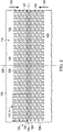
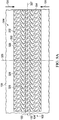
- Figure 2 is a plan view, illustrating additional details that may be associated with some embodiments of the contracting layer 114.
- the contracting layer 114 may include a plurality of holes 128 or perforations extending through the contracting layer 114 to form walls 130 extending through the contracting layer 114.
- the walls 130 may be generally parallel to the thickness 126 of the contracting layer 114.
- the walls 130 may be generally perpendicular to the surface of the contracting layer 114.
- the holes 128 may have a hexagonal shape as shown.
- the contracting layer 114 may cover the opening 120 in the tissue surface 105 of the tissue site 102.
- the contracting layer 114 may have a first orientation line 127 and a second orientation line 129 that is perpendicular to the first orientation line 127.
- an orientation line such as the first orientation line 127 or the second orientation line 129, may be a line of symmetry of the contracting layer 114.
- a line of symmetry may be, for example, an imaginary line across a surface of the contracting layer 114 defining a fold line such that if the contracting layer 114 is folded on the line of symmetry, the holes 128 and the walls 130 would be coincidentally aligned.
- the first orientation line 127 and the second orientation line 129 may be lines used to orient the contracting layer 114 relative to the tissue site 102.
- the first orientation line 127 and the second orientation line 129 may be used to refer to the desired directions of contraction for the contracting layer 114.
- the desired direction of contraction may be parallel to the second orientation line 129 and perpendicular to the first orientation line 127.
- the contracting layer 114 may be placed at the tissue site 102 so that the first orientation line 127 is parallel to the opening 120 and may cover portions of the tissue surface 105 on both sides of the opening 120.
- the first orientation line 127 may be coincident with the opening 120.
- the contracting layer 114 is shown as having a generally rectangular shape including longitudinal edges 132 and latitudinal edges 134, the contracting layer 114 may have other shapes.
- the contracting layer 114 may have a diamond, square, or circular shape.
- the shape of the contracting layer 114 may be selected to accommodate the type of tissue site being treated.
- the first orientation line 127 may be parallel to the longitudinal edges 132.
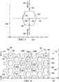
- the hole 128 may include a center 136 and a perimeter 138.
- the hole 128 may have a perforation shape factor (PSF).
- the perforation shape factor (PSF) may represent an orientation of the hole 128 relative to the first orientation line 127 and the second orientation line 129.
- the perforation shape factor (PSF) is a ratio of 1 ⁇ 2 a maximum length of the hole 128 that is parallel to the second orientation line 129 to 1 ⁇ 2 a maximum length of the hole 128 that is parallel to the first orientation line 127.
- the hole 128 may have an X-axis 142 extending through the center 136 between opposing vertices of the hexagon and parallel to the first orientation line 127, and a Y-axis 140 extending through the center 136 between opposing sides of the hexagon and parallel to the second orientation line 129.
- the perforation shape factor (PSF) of the hole 128 may be defined as a ratio of a line segment 144 on the Y-axis 140 extending from the center 136 to the perimeter 138 of the hole 128, to a line segment 146 on the X-axis 142 extending from the center 136 to the perimeter 138 of the hole 128.
- the perforation shape factor (PSF) would be 2.69/2.5 or about 1.08.
- the hole 128 may be oriented relative to the first orientation line 127 and the second orientation line 129 so that the perforation shape factor (PSF) may be about 1.07 or 1.1.
- the contracting layer 114 may include the plurality of holes 128 aligned in a pattern of parallel rows.
- the pattern of parallel rows may include a first row 148 of the holes 128, a second row 150 of the holes 128, and a third row 152 of the holes 128.
- the centers 136 of the holes 128 in adjacent rows may be characterized by being offset from the second orientation line 129 along the first orientation line 127.
- a line connecting the centers of adjacent rows may form a strut angle (SA) with the first orientation line 127.
- SA strut angle
- a first hole 128A in the first row 148 may have a center 136A
- a second hole 128B in the second row 150 may have a center 136B.
- a strut line 154 may connect the center 136A with the center 136B.
- the strut line 154 may form an angle 156 with the first orientation line 127.
- the angle 156 may be the strut angle (SA) of the contracting layer 114.
- the strut angle (SA) may be less than about 90°.
- the strut angle (SA) may be between about 30° and about 70° relative to the first orientation line 127.
- the strut angle (SA) may be about 66° from the first orientation line 127.
- a stiffness of the contracting layer 114 in a direction parallel to the first orientation line 127 may increase. Increasing the stiffness of the contracting layer 114 parallel to the first orientation line 127 may increase the compressibility of the contracting layer 114 perpendicular to the first orientation line 127. Consequently, if negative pressure is applied to the contracting layer 114, the contracting layer 114 may be more compliant or compressible in a direction perpendicular to the first orientation line 127. By increasing the compressibility of the contracting layer 114 in a direction perpendicular to the first orientation line 127, the contracting layer 114 may collapse to apply the closing force 131 to the opening 120 of the tissue site 102, as described in more detail below.
- the centers 136 of the holes 128 in alternating rows may be spaced from each other parallel to the second orientation line 129 by a length 158.
- the length 158 may be greater than an effective diameter of the hole 128. If the centers 136 of holes 128 in alternating rows are separated by the length 158, the walls 130 parallel to the first orientation line 127 may be considered continuous. Generally, the walls 130 may be continuous if the walls 130 do not have any discontinuities or breaks between holes 128.
- the holes 128 in the contracting layer 114 may leave void spaces in the contracting layer 114 and on the surface of the contracting layer 114 so that only the walls 130 of the contracting layer 114 remain with a surface available to contact the tissue surface 105. It may be desirable to minimize the walls 130 so that the holes 128 may collapse, causing the contracting layer 114 to collapse and generate the closing force 131 in a direction perpendicular to the first orientation line 127. However, it may also be desirable not to minimize the walls 130 so much that the contracting layer 114 becomes too fragile for sustaining the application of a negative pressure.
- the void space percentage (VS) of the holes 128 may be equal to the percentage of the volume or surface area of the void spaces created by the holes 128 to the total volume or surface area of the contracting layer 114. In some embodiments, the void space percentage (VS) may be between about 40% and about 60%. In other embodiments, the void space percentage (VS) may be about 55%.
- the holes 128 may be formed during molding of the contracting layer 114. In other embodiments, the holes 128 may be formed by cutting, melting, or vaporizing the contracting layer 114 after the contracting layer 114 is formed. For example, the holes 128 may be formed in the contracting layer 114 by laser cutting the compressed foam of the contracting layer 114. In some embodiments, an effective diameter of the holes 128 may be selected to permit flow of particulates through the holes 128. An effective diameter of a non-circular area may be defined as a diameter of a circular area having the same surface area as the non-circular area. In some embodiments, each hole 128 may have an effective diameter of about 3.5 mm.
- each hole 128 may have an effective diameter between about 5 mm and about 20 mm.
- the effective diameter of the holes 128 should be distinguished from the porosity of the material forming the walls 130 of the contracting layer 114.
- an effective diameter of the holes 128 is an order of magnitude larger than the effective diameter of the pores of a material forming the contracting layer 114.
- the effective diameter of the holes 128 may be larger than about 1 mm, while the walls 130 may be formed from GranuFoam® material having a pore size less than about 600 microns.
- the pores of the walls 130 may not create openings that extend all the way through the material.
- the holes 128 may form a pattern depending on the geometry of the holes 128 and the alignment of the holes 128 between adjacent and alternating rows in the contracting layer 114 with respect to the first orientation line 127. If the contracting layer 114 is subjected to negative pressure, the holes 128 of the contracting layer 114 may collapse. In some embodiments the void space percentage (VS), the perforation shape factor (PSF), and the strut angle (SA) may cause the contracting layer 114 to collapse along the second orientation line 129 perpendicular to the first orientation line 127 as shown in more detail in Figure 5 .
- VS void space percentage
- PSF perforation shape factor
- SA strut angle
- the contracting layer 114 may generate the closing force 131 along the second orientation line 129 such that the tissue surface 105 is contracted in the same direction to facilitate closure of the opening 120 and draw the first wall 122 to the second wall 124 as shown in more detail in Figure 5 .
- the closing force 131 may be optimized by adjusting the factors described above, as set forth in Table 1 below.
- the holes 128 may be hexagonal, have a strut angle (SA) of approximately 66°, a void space percentage (VS) of about 55%, a firmness factor (FF) of 5, a perforation shape factor (PSF) of 1.07, and an effective diameter of about 5 mm. If the contracting layer 114 is subjected to a negative pressure of about -125 mm Hg, the closing force 131 asserted by the contracting layer 114 may be about 13.3 N. If the effective diameter of the holes 128 of the contracting layer 114 is increased to 10 mm, the closing force 131 may be decreased to about 7.5 N.
- SA strut angle
- VS void space percentage
- FF firmness factor
- PSF perforation shape factor
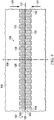
- Figure 6 is a perspective sectional view with a portion shown in elevation, illustrating additional details that may be associated with some embodiments of the negative-pressure therapy system 100.
- the contracting layer 114 is in the second position, or contracted position, of Figure 5 .
- negative pressure may be supplied to the sealed therapeutic environment 118 with the negative-pressure source 106.
- the contracting layer 114 may collapse from the position illustrated in Figure 1 to the position illustrated in Figure 6 .
- the thickness 126 of the contracting layer 114 may remain substantially the same.
- negative pressure may be supplied to the sealed therapeutic environment 118 until a pressure in the sealed therapeutic environment 118 is about a therapy pressure.
- the sealed therapeutic environment 118 may remain at the therapy pressure for a therapy period.
- the therapy period may be a time period that allows for opposing sides of the opening 120 to heal.
- the therapy period may be cyclic, having a period in which negative pressure may be applied to the tissue site 102 and a period in which negative pressure may be vented from the tissue site 102. In other embodiments, the therapy period may be longer or as shorter as needed to supply appropriate negative-pressure therapy to the tissue site 102.
- the contracting layer 114 may exert the closing force 131 parallel to the tissue surface 105 of the tissue site 102 toward the opening 120.
- the closing force 131 may urge the first wall 122 and the second wall 124 toward one another.
- the closing force 131 may close the opening 120.
- the closing force 131 may also relieve localized stresses that may be caused by the stitches 103, reducing the risk of additional trauma to the tissue site 102.
- Figure 7 is a plan view, illustrating additional details that may be associated with some embodiments of a contracting layer 214.
- the contracting layer 214 may be similar to the contracting layer 114 and operate as described above with respect to Figures 1-6 . Similar elements may have similar numbers indexed to 200.
- the contracting layer 214 is shown as having a generally rectangular shape including longitudinal edges 232 and latitudinal edges 234.
- the contracting layer 214 may have a first orientation line 227 and a second orientation line 229 that is perpendicular to the first orientation line 227.
- the first orientation line 227 and the second orientation line 229 may be used to refer to the desired directions of contraction for the contracting layer 214.
- the desired direction of contraction may be parallel to the second orientation line 229 and perpendicular to the first orientation line 227.
- the contracting layer 214 may be placed at the tissue site 102 so that the first orientation line 227 is parallel to the opening 120 and may cover portions of the tissue surface 105 on both sides of the opening 120.
- the first orientation line 227 may be coincident with the opening 120.
- the contracting layer 214 may include a plurality of holes 228 or perforations extending through the contracting layer 214.
- the walls 230 of the holes 228 may extend through the contracting layer 214 parallel to the thickness 126 of the contracting layer 214.
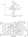
- the holes 228 may have a circular shape as shown.
- the hole 228 may include a center 236, a perimeter 238, and the perforation shape factor (PSF).
- the hole 228 may have an X-axis 242 extending through the center 236 parallel to the first orientation line 227, and a Y-axis 240 extending through the center 236 parallel to the second orientation line 229.
- the perforation shape factor (PSF) of the hole 228 may be defined as a ratio of a line segment 244 on the Y-axis 240 extending from the center 236 to the perimeter 238 of the hole 228, to a line segment 246 on the X-axis 242 extending from the center 236 to the perimeter 238 of the hole 228. If a length of the line segment 244 is 2.5 mm and the length of the line segment 246 is 2.5 mm, the perforation shape factor (PSF) would be 2.5/2.5 or about 1.
- the contracting layer 214 may include the plurality of holes 228 aligned in a pattern of parallel rows.
- the pattern of parallel rows may include a first row 248 of the holes 228, a second row 250 of the holes 228, and a third row 252 of the holes 228.
- the X-axis 242 of Figure 8A of each hole 228 may be parallel to the first orientation line 227 of Figure 8B .
- the centers 236 of the holes 228 in adjacent rows, for example, the first row 248 and the second row 250, may be characterized by being offset from the second orientation line 229 along the first orientation line 227.
- a line connecting the centers of adjacent rows may form the strut angle (SA) with the first orientation line 227.
- SA strut angle
- a first hole 228A in the first row 248 may have a center 236A
- a second hole 228B in the second row 250 may have a center 236B.
- a strut line 254 may connect the center 236A with the center 236B.
- the strut line 254 may form an angle 256 with the first orientation line 227.
- the angle 256 may be the strut angle (SA) of the contracting layer 214.
- the strut angle (SA) may be less than about 90°.
- the strut angle (SA) may be between about 30° and about 70° relative to the first orientation line 227.
- the contracting layer 214 may be more compliant or compressible in a direction perpendicular to the first orientation line 227.
- the contracting layer 214 may collapse to apply a closing force to the opening 120 of the tissue site 102, as described in more detail below.
- the centers 236 of the holes 228 in alternating rows may be spaced from each other parallel to the second orientation line 229 by a length 258.
- the length 258 may be greater than an effective diameter of the hole 228.
- the holes 228 in the contracting layer 214 may leave void spaces in the contracting layer 214 and on the surface of the contracting layer 214 so that only walls 230 of the contracting layer 214 remain with a surface available to contact the tissue surface 105. It may be desirable to minimize the walls 230 so that the holes 228 collapse, causing the contracting layer 214 to collapse to generate the closing force 131 in a direction perpendicular to the first orientation line 227. However, it may also be desirable not to minimize the walls 230 so much that the contracting layer 214 becomes too fragile for sustaining the application of a negative pressure.
- the void space percentage (VS) of the holes 228 may be equal to the percentage of the volume or surface area of the void spaces created by the holes 228 to the total volume or surface area of the contracting layer 214. In some embodiments, the void space percentage (VS) may be between about 40% and about 60%. In other embodiments, the void space percentage (VS) may be about 54%.
- a diameter of the holes 228 may be selected to permit flow of particulates through the holes 228.
- each hole 228 may have a diameter of about 5 mm. In other embodiments, each hole 228 may have an effective diameter between about 3.5 mm and about 20 mm.
- the holes 228 may form a pattern depending on the geometry of the holes 228 and the alignment of the holes 228 between adjacent and alternating rows in the contracting layer 214 with respect to the first orientation line 227. If the contracting layer 214 is subjected to negative pressure, the holes 228 of the contracting layer 214 may collapse. In some embodiments, the void space percentage (VS), the perforation shape factor (PSF), and the strut angle (SA) may cause the contracting layer 214 to collapse along the second orientation line 229 perpendicular to the first orientation line 227.
- VS void space percentage
- PSF perforation shape factor
- SA strut angle
- the contracting layer 214 may generate the closing force 131 along the second orientation line 229 such that the tissue surface 105 is contracted in the same direction to facilitate closure of the opening 120.
- the closing force 131 may be optimized by adjusting the factors described above as set forth in Table 1 below.
- the holes 228 may be circular, have a strut angle (SA) of approximately 37°, a void space percentage (VS) of about 54%, a firmness factor (FF) of 5, a perforation shape factor (PSF) of 1, and a diameter of about 5 mm.
- the contracting layer 214 may assert the closing force 131 of approximately 11.9 N. If the diameter of the holes 228 of the contracting layer 214 is increased to 20 mm, the void space percentage (VS) changed to 52%, the strut angle (SA) changed to 52°, and the perforation shape factor (PSF) and the firmness factor (FF) remain the same, the closing force 131 may be decreased to about 6.5 N.
- Figure 9A is a plan view, illustrating additional details that may be associated with some embodiments of a contracting layer 314.
- the contracting layer 314 may be similar to the contracting layer 114 and operate as described above with respect to Figures 1-6 . Similar elements may have similar reference numbers indexed to 300.
- the contracting layer 314 may cover the opening 120 in the tissue surface 105 of the tissue site 102.
- the contracting layer 314 may have a first orientation line 327 and a second orientation line 329 that is perpendicular to the first orientation line 327.
- the first orientation line 327 and the second orientation line 329 may be used to refer to the desired directions of contraction for the contracting layer 314.
- the desired direction of contraction may be parallel to the second orientation line 329 and perpendicular to the first orientation line 327.
- the contracting layer 314 may be placed at the tissue site 102 so that the first orientation line 327 is parallel to the opening 120 and may cover portions of the tissue surface 105 on both sides of the opening 120.
- the first orientation line 327 may be coincident with the opening 120.
- the contracting layer 314 may include a plurality of holes 328 or perforations extending through the contracting layer 314.
- the walls 330 of the holes 328 may extend through the contracting layer 314 parallel to the thickness 126 of the contracting layer 314.
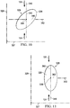
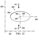
- the holes 328 may have an ovoid shape as shown.
- the hole 328 may include a center 336, a perimeter 338, and a perforation shape factor (PSF).
- PSF perforation shape factor
- the hole 328 may have an X-axis 342 extending through the center 336 parallel to the first orientation line 327, and a Y-axis 340 extending through the center 336 parallel to the second orientation line 329.
- the perforation shape factor (PSF) of the hole 328 may be defined as a ratio of a line segment 344 on the Y-axis 340 extending from the center 336 to the perimeter 338 of the hole 328, to a line segment 346 on the X-axis 342 extending from the center 336 to the perimeter 338 of the hole 328. If a length of the line segment 344 is 2.5 mm and the length of the line segment 346 is 2.5 mm, the perforation shape factor (PSF) would be 2.5/2.5 or about 1.
- the perforation shape factor (PSF) may change.
- the perforation shape factor (PSF) is now the ratio of a line segment 360 on the Y-axis 340 extending from the center 336 to the perimeter 338 of the hole 328, to a line segment 362 on the X-axis 342 extending from the center 336 to the perimeter 338 of the hole 328. If a length of the line segment 360 is 5 mm and the length of the line segment 362 is 2.5 mm, the perforation shape factor (PSF) would be 5/2.5 or about 2.
- the perforation shape factor (PSF) may change.
- the perforation shape factor (PSF) is now the ratio of a line segment 364 on the Y-axis 340 extending from the center 336 to the perimeter 338 of the hole 328, to a line segment 366 on the X-axis 342 extending from the center 336 to the perimeter 338 of the hole 328. If a length of the line segment 364 is 2.5 mm and the length of the line segment 366 is 5 mm, the perforation shape factor (PSF) would be 2.5/5 or about 1/2.
- the contracting layer 314 may include the plurality of holes 328 aligned in a pattern of parallel rows.
- the pattern of parallel rows may include a first row 348 of the holes 328, a second row 350 of the holes 328, and a third row 352 of the holes 328.
- the X-axis 342 of Figures 10, 11 , and 12 of each hole 328 may be parallel to the first orientation line 327 of Figure 9B .
- the centers 336 of the holes 328 in adjacent rows, for example, the first row 348 and the second row 350, may be characterized by being offset from the second orientation line 329 along the first orientation line 327.
- a line connecting the centers of adjacent rows may form a strut angle (SA) with the first orientation line 327.
- SA strut angle
- a first hole 328A in the first row 348 may have a center 336A
- a second hole 328B in the second row 350 may have a center 336B.
- a strut line 354 may connect the center 336A with the center 336B.
- the strut line 354 may form an angle 356 with the first orientation line 327.
- the angle 356 may be the strut angle (SA) of the contracting layer 314.
- the strut angle (SA) may be less than about 90°.
- the strut angle (SA) may be between about 30° and about 70° relative to the first orientation line 327.
- the contracting layer 314 may be more compliant or compressible in a direction perpendicular to the first orientation line 327.
- the contracting layer 314 may collapse to apply the closing force 131 to the opening 120 of the tissue site 102, as described in more detail below.
- the centers 336 of the holes 328 in alternating rows may be spaced from each other parallel to the second orientation line 329 by a length 358.
- the length 358 may be greater than an effective diameter of the hole 328. If the centers 336 of holes 328 in alternating rows are separated by the length 358, the walls 330 parallel to the first orientation line 327 may be considered continuous. Generally, the walls 330 may be continuous if the walls 330 do not have any discontinuities or breaks between holes 328.
- the holes 328 in the contracting layer 314 may leave void spaces in the contracting layer 314 and on the surface of the contracting layer 314 so that only walls 330 of the contracting layer 314 remain with a surface available to contact the tissue surface 105. It may be desirable to minimize the walls 330 so that the holes 328 may collapse, causing the contracting layer 314 to collapse the closing force 131 in a direction perpendicular to the first orientation line 327. However, it may also be desirable not to minimize the walls 330 so much that the contracting layer 314 becomes too fragile for sustaining the application of a negative pressure.
- the void space percentage (VS) of the holes 328 may be equal to the percentage of the volume or surface area of the void spaces created by the holes 328 to the total volume or surface area of the contracting layer 314. In some embodiments, the void space percentage (VS) may be between about 40% and about 60%. In other embodiments, the void space percentage (VS) may be about 56%.
- an effective diameter of the holes 328 may be selected to permit flow of particulates through the holes 328.
- each hole 328 may have an effective diameter of about 7 mm. In other embodiments, each hole 328 may have an effective diameter between about 2.5 mm and about 20 mm.
- the holes 328 may form a pattern depending on the geometry of the holes 328 and the alignment of the holes 328 between adjacent and alternating rows in the contracting layer 314 with respect to the first orientation line 327. If the contracting layer 314 is subjected to negative pressure, the holes 328 of the contracting layer 314 may collapse, causing the contracting layer 314 to collapse along the second orientation line 329 perpendicular to the first orientation line 327.
- the contracting layer 314 may generate the closing force 131 along the second orientation line 329 such that the tissue surface 105 is contracted in the same direction to facilitate closure of the opening 120.
- the closing force 131 may be optimized by adjusting the factors described above as set forth in Table 1 below.
- the holes 328 may be ovular, have a strut angle (SA) of approximately 47°, a void space percentage (VS) of about 56%, a firmness factor (FF) of 5, a perforation shape factor (PSF) of 1, and an effective diameter of about 7 mm (where the major axis is about 10 mm and the minor axis is about 5 mm). If the contracting layer 314 is subjected to a negative pressure of about -125 mm Hg, the contracting layer 314 may assert the closing force 131 of approximately 13.5 N.
- SA strut angle
- VS void space percentage
- FF firmness factor
- PSF perforation shape factor
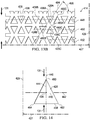
- Figure 13A is a plan view, illustrating additional details that may be associated with some embodiments of a contracting layer 414.
- the contracting layer 414 may be similar to the contracting layer 114 and operate as described with respect to Figures 1-6 . Similar elements may have similar reference numbers indexed to 400.
- the contracting layer 414 is shown as having a generally rectangular shape including longitudinal edges 432 and latitudinal edges 434.
- the contracting layer 414 may cover the opening 120 in the tissue surface 105 of the tissue site 102.
- the contracting layer 414 may have a first orientation line 427 and a second orientation line 429 that is perpendicular to the first orientation line 427.
- the first orientation line 427 and the second orientation line 429 may be used to refer to the desired directions of contraction for the contracting layer 414.
- the desired direction of contraction may be parallel to the second orientation line 429 and perpendicular to the first orientation line 427.
- the contracting layer 414 may be placed at the tissue site 102 so that the first orientation line 427 is parallel to the opening 120 and may cover portions of the tissue surface 105 on both sides of the opening 120.
- the first orientation line 427 may be coincident with the opening 120.
- the contracting layer 414 may include a plurality of holes 428 or perforations extending through the contracting layer 414.
- the walls 430 of the holes 428 may extend through the contracting layer 414 parallel to the thickness 126 of the contracting layer 414.
- the holes 428 may have a triangular shape as shown.
- the hole 428 may include a center 436, a perimeter 438, and a perforation shape factor (PSF).
- the hole 428 may include a first vertex 460, a second vertex 462, and a third vertex 464.
- the hole 428 may have an X-axis 442 extending through the center 436 parallel to the first orientation line 427, and a Y-axis 440 extending through the center 436 parallel to the second orientation line 429.
- the perforation shape factor (PSF) of the hole 428 may be defined as a ratio of a line segment 444 on the Y-axis 440 extending from the center 436 to the perimeter 438 of the hole 428, to a line segment 446 on the X-axis 442 extending from the center 436 to the perimeter 438 of the hole 428. If a length of the line segment 444 is 1.1 mm and the length of the line segment 446 is 1 mm, the perforation shape factor (PSF) would be 1.1/1 or about 1.1.
- the contracting layer 414 may include the plurality of holes 428 aligned in a pattern of parallel rows.
- the pattern of parallel rows may include a first row 448 of the holes 428, a second row 450 of the holes 428, and a third row 452 of the holes 428.
- the X-axis 442 of Figure 14 of each hole 428 may be parallel to the first orientation line 427 of Figure 13B .
- a first hole 428A in the first row 448 may be oriented so that the first vertex 460A of a first hole 428A may be between the first orientation line 427 and a leg of the first hole 428A opposite the first vertex 460A.
- a hole 428C that is adjacent the first hole 428A in the first row 448 may be oriented so that the first vertex 460C may be oriented opposite the first hole 428A.
- the centers 436 of the holes 428 in adjacent rows having the first vertex 460 oriented in a same direction, for example, the first row 448 and the second row 450, may be characterized by being offset from the second orientation line 429 along the first orientation line 427.
- a line connecting the centers of adjacent rows may form a strut angle (SA) with the first orientation line 427.
- SA strut angle
- a first hole 428A in the first row 448 may have a center 436A
- a second hole 428B in the second row 450 may have a center 436B and a first vertex 460B.
- a strut line 454 may connect the center 436A with the center 436B.
- the strut line 454 may form an angle 456 with the first orientation line 427.
- the angle 456 may be the strut angle (SA) of the contracting layer 414.
- the strut angle (SA) may be less than about 90°.
- the strut angle (SA) may be between about 40° and about 70° relative to the first orientation line 427.
- the contracting layer 414 may be more compliant or compressible in a direction perpendicular to the first orientation line 427. By increasing the compressibility of the contracting layer 414 in a direction perpendicular to the first orientation line 427, the contracting layer 414 may collapse to apply the closing force 131 to the opening 120 of the tissue site 102, as described in more detail below.
- the holes 428 in the contracting layer 414 may leave void spaces in the contracting layer 414 and on the surface of the contracting layer 414 so that only walls 430 of the contracting layer 414 remain with a surface available to contact the tissue surface 105. It may be desirable to minimize the walls 430 so that the holes 428 may collapse, causing the contracting layer 414 to generate the closing force 131 in a direction perpendicular to the first orientation line 427. However, it may also be desirable not to minimize the walls 430 so much that the contracting layer 414 becomes too fragile for sustaining the application of a negative pressure.
- the void space percentage (VS) of the holes 428 may be equal to the percentage of the volume or surface area of the void spaces created by the holes 428 to the total volume or surface area of the contracting layer 414. In some embodiments, the void space percentage (VS) may be between about 40% and about 60%. In other embodiments, the void space percentage (VS) may be about 56%.
- an effective diameter of the holes 428 may be selected to permit flow of particulates through the holes 428.
- each hole 428 may have an effective diameter of about 7 mm. In other embodiments, each hole 428 may have an effective diameter between about 2.5 mm and about 20 mm.
- the holes 428 may form a pattern depending on the geometry of the holes 428 and the alignment of the holes 428 between adjacent and alternating rows in the contracting layer 414 with respect to the first orientation line 427. If the contracting layer 414 is subjected to negative pressure, the holes 428 of the contracting layer 414 may collapse. In some embodiments, the void space percentage (VS), the perforation shape factor (PSF), and the strut angle (SA) may cause the contracting layer 414 to collapse along the second orientation line 429 perpendicular to the first orientation line 427.
- VS void space percentage
- PSF perforation shape factor
- SA strut angle
- the contracting layer 414 may generate the closing force 131 along the second orientation line 429 such that the tissue surface 105 is contracted in the same direction to facilitate closure of the opening 120.
- the closing force 131 may be optimized by adjusting the factors described above as set forth in Table 1 below.
- the holes 428 may be triangular, have a strut angle (SA) of approximately 63°, a void space percentage (VS) of about 40%, a firmness factor (FF) of 5, a perforation shape factor (PSF) of 1.1, and an effective diameter of about 10 mm. If the contracting layer 414 is subjected to a negative pressure of about -125 mm Hg, the contracting layer 414 may assert the closing force 131 of approximately 12.2 N.
- Figure 15 is a plan view, illustrating additional details that may be associated with some embodiments of a contracting layer 514.
- the contracting layer 514 may be similar to the contracting layer 114 described above with respect to Figures 1-6 .
- the contracting layer 514 may include stripes 516 having a first density and stripes 518 having a second density.
- the stripes 516 and the stripes 518 may be vertically oriented relative to a tissue site, and in other embodiments, the stripes 516 and the stripes 518 may be horizontally oriented relative to a tissue site. In still other embodiments, the stripes 516 and the stripes 518 may be oriented at an angle relative to a tissue site.
- the second density may be greater than the first density.
- the second density may be between about 3 times and about 5 times greater than the first density.
- the contracting layer 514 may be formed from a foam, similar to GranuFoam®.
- the stripes 518 may be formed by compressing portions of the foam.
- the stripes 516 may be an uncompressed foam, and the stripes 518 may be a compressed foam having a firmness factor of about 5.
- the stripes 516 may be more compressible than the stripes 518. If the contracting layer 514 is placed under a negative-pressure, the stripes 516 may collapse before the stripes 518. In some embodiments, if the stripes 516 collapse, the contracting layer 514 may compress perpendicular to the stripes 516.
- a closing force, such as the closing force 131, generated by a contracting layer, such as the contracting layer 114, may be related to a compressive force generated by applying negative pressure at a therapy pressure to a sealed therapeutic environment.
- the closing force 131 may be proportional to a product of a therapy pressure (TP) in the sealed therapeutic environment 118, the compressibility factor (CF) of the contracting layer 114, and a surface area (A) of the contracting layer 114.
- TP therapy pressure
- CF compressibility factor
- A surface area
- the therapy pressure TP is measured in N/m 2
- the compressibility factor (CF) is dimensionless
- the area (A) is measured in m 2
- the closing force is measured in Newtons (N).
- the compressibility factor (CF) resulting from the application of negative pressure to a contracting layer may be, for example, a dimensionless number that is proportional to the product of the void space percentage (VS) of a contracting layer, the firmness factor (FF) of the contracting layer, the strut angle (SA) of the holes in the contracting layer, and the perforation shape factor (PSF) of the holes in the contracting layer.
- the relationship is expressed as follows: Compressibility Factor CF ⁇ VS * FF * sin SA * PSF
- contracting layers formed from different materials with holes of different shapes were manufactured and tested to determine the closing force of the contracting layers.
- the therapy pressure TP was about -125 mmHg and the dimensions of the contracting layer were about 200 mm by about 53 mm so that the surface area (A) of the contracting layer was about 106 cm 2 or 0.0106 m 2 .
- the closing force for a Supracor® contracting layer 114 having a firmness factor (FF) of 3 was about 13.3 where the Supracor® contracting layer 114 had hexagonal holes 128 with a distance between opposite vertices of 5 mm, a perforation shape factor (PSF) of 1.07, a strut angle (SA) of approximately 66°, and a void space percentage (VS) of about 55%.
- a similarly dimensioned GranuFoam® contracting layer 114 generated the closing force 131 of about 9.1 Newtons (N). TABLE 1 Material VS FF SA Hole Shape PSF Major diam.
- the formulas described above may not precisely describe the closing forces due to losses in force due to the transfer of the force from the contracting layer to the wound.
- the modulus and stretching of the cover 112 the modulus of the tissue site 102, slippage of the cover 112 over the tissue site 102, and friction between the protective layer 116, the contracting layer 114, and the tissue surface 105 of tissue site 102 may cause the actual value of the closing force 131 to be less than the calculated value of the closing force 131.
- the material, the void space percentage (VS), the firmness factor, the strut angle, the hole shape, the perforation shape factor (PSF), and the hole diameter may be selected to increase compression or collapse of the contracting layer 114 in a lateral direction, as shown by the closing force 131, by forming weaker walls 130.
- the factors may be selected to decrease compression or collapse of the contracting layer 114 in a lateral direction, as shown by the closing force 131, by forming stronger walls 130.
- the factors described herein can be selected to decrease or increase the compression or collapse of the contracting layer 114 perpendicular to the closing force 131.
- closing forces generated by the described contracting layers meet or exceed other contracting layers designed for a similar purpose.
- the described contracting layers may also assist in closure of an incisional tissue site by distributed force along a length of the incisional opening, reducing potential trauma that may be caused by point loading such as with sutures, staples or hooks.
Landscapes
- Health & Medical Sciences (AREA)
- Heart & Thoracic Surgery (AREA)
- General Health & Medical Sciences (AREA)
- Engineering & Computer Science (AREA)
- Biomedical Technology (AREA)
- Life Sciences & Earth Sciences (AREA)
- Animal Behavior & Ethology (AREA)
- Vascular Medicine (AREA)
- Public Health (AREA)
- Veterinary Medicine (AREA)
- Anesthesiology (AREA)
- Hematology (AREA)
- Media Introduction/Drainage Providing Device (AREA)
- Surgical Instruments (AREA)
- External Artificial Organs (AREA)
Applications Claiming Priority (4)
| Application Number | Priority Date | Filing Date | Title |
|---|---|---|---|
| US201461991174P | 2014-05-09 | 2014-05-09 | |
| EP17186355.8A EP3263079B8 (en) | 2014-05-09 | 2015-05-08 | Dressing with contracting layer for linear tissue sites |
| EP15723813.0A EP3139878B1 (en) | 2014-05-09 | 2015-05-08 | Dressing with contracting layer for linear tissue sites |
| PCT/US2015/030027 WO2015172108A1 (en) | 2014-05-09 | 2015-05-08 | Dressing with contracting layer for linear tissue sites |
Related Parent Applications (3)
| Application Number | Title | Priority Date | Filing Date |
|---|---|---|---|
| EP17186355.8A Division EP3263079B8 (en) | 2014-05-09 | 2015-05-08 | Dressing with contracting layer for linear tissue sites |
| EP17186355.8A Division-Into EP3263079B8 (en) | 2014-05-09 | 2015-05-08 | Dressing with contracting layer for linear tissue sites |
| EP15723813.0A Division EP3139878B1 (en) | 2014-05-09 | 2015-05-08 | Dressing with contracting layer for linear tissue sites |
Publications (1)
| Publication Number | Publication Date |
|---|---|
| EP3797744A1 true EP3797744A1 (en) | 2021-03-31 |
Family
ID=53191845
Family Applications (3)
| Application Number | Title | Priority Date | Filing Date |
|---|---|---|---|
| EP20202628.2A Pending EP3797744A1 (en) | 2014-05-09 | 2015-05-08 | Dressing with contracting layer for linear tissue sites |
| EP15723813.0A Active EP3139878B1 (en) | 2014-05-09 | 2015-05-08 | Dressing with contracting layer for linear tissue sites |
| EP17186355.8A Active EP3263079B8 (en) | 2014-05-09 | 2015-05-08 | Dressing with contracting layer for linear tissue sites |
Family Applications After (2)
| Application Number | Title | Priority Date | Filing Date |
|---|---|---|---|
| EP15723813.0A Active EP3139878B1 (en) | 2014-05-09 | 2015-05-08 | Dressing with contracting layer for linear tissue sites |
| EP17186355.8A Active EP3263079B8 (en) | 2014-05-09 | 2015-05-08 | Dressing with contracting layer for linear tissue sites |
Country Status (7)
| Country | Link |
|---|---|
| US (3) | US9974694B2 (enExample) |
| EP (3) | EP3797744A1 (enExample) |
| JP (2) | JP6749248B2 (enExample) |
| CN (2) | CN106255480B (enExample) |
| AU (2) | AU2015255723B2 (enExample) |
| CA (1) | CA2947302C (enExample) |
| WO (1) | WO2015172108A1 (enExample) |
Families Citing this family (107)
| Publication number | Priority date | Publication date | Assignee | Title |
|---|---|---|---|---|
| US9820888B2 (en) | 2006-09-26 | 2017-11-21 | Smith & Nephew, Inc. | Wound dressing |
| GB0808376D0 (en) | 2008-05-08 | 2008-06-18 | Bristol Myers Squibb Co | Wound dressing |
| GB0817796D0 (en) | 2008-09-29 | 2008-11-05 | Convatec Inc | wound dressing |
| US9061095B2 (en) | 2010-04-27 | 2015-06-23 | Smith & Nephew Plc | Wound dressing and method of use |
| GB201020236D0 (en) | 2010-11-30 | 2011-01-12 | Convatec Technologies Inc | A composition for detecting biofilms on viable tissues |
| CN103347561B (zh) | 2010-12-08 | 2016-09-07 | 康沃特克科技公司 | 用于评估伤口分泌液的集成系统 |
| JP5833134B2 (ja) | 2010-12-08 | 2015-12-16 | コンバテック・テクノロジーズ・インコーポレイテッドConvatec Technologies Inc | 創傷部位から滲出液を除去するための方法およびシステム |
| JP6151186B2 (ja) | 2010-12-08 | 2017-06-21 | コンバテック・テクノロジーズ・インコーポレイテッドConvatec Technologies Inc | 創傷滲出液システム付属装置 |
| US9421132B2 (en) | 2011-02-04 | 2016-08-23 | University Of Massachusetts | Negative pressure wound closure device |
| WO2012106590A2 (en) | 2011-02-04 | 2012-08-09 | University Of Massachusetts | Negative pressure wound closure device |
| AU2012333210B2 (en) | 2011-06-24 | 2017-01-19 | Solventum Intellectual Properties Company | Reduced-pressure dressings employing tissue-fixation elements |
| GB201115182D0 (en) | 2011-09-02 | 2011-10-19 | Trio Healthcare Ltd | Skin contact material |
| GB2497406A (en) | 2011-11-29 | 2013-06-12 | Webtec Converting Llc | Dressing with a perforated binder layer |
| GB201120693D0 (en) | 2011-12-01 | 2012-01-11 | Convatec Technologies Inc | Wound dressing for use in vacuum therapy |
| MX2014014265A (es) | 2012-05-22 | 2015-06-23 | Smith & Nephew | Dispositivo para cierre de heridas. |
| CN104736110B (zh) | 2012-05-24 | 2019-05-31 | 史密夫和内修有限公司 | 用于利用负压来处理和封闭伤口的装置和方法 |
| RU2015104581A (ru) | 2012-07-16 | 2016-09-10 | Смит Энд Нефью, Инк. | Устройство для закрытия раны с использованием отрицательного давления |
| WO2014096843A2 (en) | 2012-12-20 | 2014-06-26 | Convatec Technologies Inc. | Processing of chemically modified cellulosic fibres |
| WO2014165275A1 (en) | 2013-03-13 | 2014-10-09 | Smith & Nephew Inc. | Negative pressure wound closure device and systems and methods of use in treating wounds with negative pressure |
| AU2014291873B2 (en) | 2013-07-16 | 2019-01-24 | Smith & Nephew Plc | Apparatus for wound therapy |
| AU2014340232B2 (en) | 2013-10-21 | 2019-07-11 | Smith & Nephew Inc. | Negative pressure wound closure device |
| MX2016009476A (es) | 2014-01-21 | 2016-10-13 | Smith & Nephew | Aparatos para tratamiento de heridas. |
| CN110974539A (zh) | 2014-01-21 | 2020-04-10 | 史密夫及内修公开有限公司 | 用于负压伤口治疗的可塌缩敷料 |
| US10898217B2 (en) | 2014-05-09 | 2021-01-26 | Kci Licensing, Inc. | Dressing providing apertures with multiple orifice sizes for negative-pressure therapy |
| AU2015255726B2 (en) | 2014-05-09 | 2020-03-05 | Solventum Intellectual Properties Company | Disruptive dressing for use with negative pressure and fluid instillation |
| CA2947298C (en) | 2014-05-09 | 2023-06-06 | Kci Licensing, Inc. | Debriding dressing for use with negative pressure and fluid instillation |
| AU2015255723B2 (en) | 2014-05-09 | 2019-09-19 | Solventum Intellectual Properties Company | Dressing with contracting layer for linear tissue sites |
| EP3157484B1 (en) | 2014-06-18 | 2020-02-26 | Smith & Nephew plc | Wound dressing |
| HUE049136T2 (hu) | 2015-04-27 | 2020-08-28 | Smith & Nephew | Csökkentett nyomású berendezések |
| EP4209201A1 (en) | 2015-04-29 | 2023-07-12 | Smith & Nephew, Inc. | Negative pressure wound closure device |
| GB2543544A (en) | 2015-10-21 | 2017-04-26 | Brightwake Ltd | Wound dressing |
| US10575991B2 (en) | 2015-12-15 | 2020-03-03 | University Of Massachusetts | Negative pressure wound closure devices and methods |
| US10814049B2 (en) | 2015-12-15 | 2020-10-27 | University Of Massachusetts | Negative pressure wound closure devices and methods |
| WO2017153357A1 (en) | 2016-03-07 | 2017-09-14 | Smith & Nephew Plc | Wound treatment apparatuses and methods with negative pressure source integrated into wound dressing |
| CA3019436A1 (en) | 2016-03-30 | 2017-10-05 | Qualizyme Diagnostics Gmbh & Co Kg | Detecting microbial infection in wounds |
| SG11201808488XA (en) | 2016-03-30 | 2018-10-30 | Convatec Technologies Inc | Detecting microbial infections in wounds |
| AU2017256692B2 (en) | 2016-04-26 | 2022-03-03 | Smith & Nephew Plc | Wound dressings and methods of use with integrated negative pressure source having a fluid ingress inhibition component |
| US11096831B2 (en) | 2016-05-03 | 2021-08-24 | Smith & Nephew Plc | Negative pressure wound therapy device activation and control |
| EP3452131B1 (en) | 2016-05-03 | 2025-01-01 | Smith & Nephew plc | Systems and methods for driving negative pressure sources in negative pressure therapy systems |
| US11173240B2 (en) | 2016-05-03 | 2021-11-16 | Smith & Nephew Plc | Optimizing power transfer to negative pressure sources in negative pressure therapy systems |
| GB201608099D0 (en) | 2016-05-09 | 2016-06-22 | Convatec Technologies Inc | Negative pressure wound dressing |
| JP2019525799A (ja) | 2016-07-08 | 2019-09-12 | コンバテック・テクノロジーズ・インコーポレイテッドConvatec Technologies Inc | 流体収集装置 |
| EP3871645B1 (en) | 2016-07-08 | 2022-05-04 | ConvaTec Technologies Inc. | Flexible negative pressure system |
| ES2912094T3 (es) | 2016-07-08 | 2022-05-24 | Convatec Technologies Inc | Detección de flujo de fluidos |
| CN109561994B (zh) | 2016-08-25 | 2022-03-15 | 史密夫及内修公开有限公司 | 吸收性负压伤口疗法敷料 |
| CN109640903A (zh) | 2016-08-30 | 2019-04-16 | 史密夫及内修公开有限公司 | 用于施加减压疗法的系统 |
| WO2018060144A1 (en) * | 2016-09-27 | 2018-04-05 | Smith & Nephew Plc | Wound closure devices with dissolvable portions |
| AU2017336310B2 (en) | 2016-09-30 | 2022-12-08 | Smith & Nephew Plc | Negative pressure wound treatment apparatuses and methods with integrated electronics |
| WO2019053101A1 (en) | 2017-09-13 | 2019-03-21 | Smith & Nephew Plc | APPARATUS AND METHODS FOR NEGATIVE PRESSURE WOUND TREATMENT WITH INTEGRATED ELECTRONICS |
| WO2018060412A1 (en) | 2016-09-30 | 2018-04-05 | Smith & Nephew Plc | Negative pressure wound treatment apparatuses and methods with integrated electronics |
| US11617684B2 (en) * | 2016-11-02 | 2023-04-04 | Smith & Nephew, Inc. | Wound closure devices |
| US12005181B2 (en) | 2016-12-12 | 2024-06-11 | Smith & Nephew Plc | Pressure wound therapy status indication via external device |
| EP3554573B1 (en) * | 2016-12-16 | 2025-04-30 | Smith & Nephew PLC | Negative pressure wound closure device |
| CN110582257B (zh) | 2017-03-08 | 2022-03-15 | 史密夫及内修公开有限公司 | 存在故障条件时的负压伤口治疗装置控制 |
| JP7121050B2 (ja) | 2017-05-09 | 2022-08-17 | スミス アンド ネフュー ピーエルシー | 陰圧創傷療法システムの冗長制御 |
| US11351063B2 (en) * | 2017-06-07 | 2022-06-07 | Kci Licensing, Inc. | Composite dressings for improved granulation and reduced maceration with negative-pressure treatment |
| AU2018281120A1 (en) * | 2017-06-07 | 2020-01-02 | 3M Innovative Properties Company | Peel and place dressing for negative-pressure treatment |
| WO2018226707A1 (en) | 2017-06-07 | 2018-12-13 | Kci Licensing, Inc. | Composite dressings for improved granulation reduced maceration with negative-pressure treatment |
| AU2018282148A1 (en) | 2017-06-07 | 2019-10-31 | 3M Innovative Properties Company | Composite dressings for improved granulation and reduced maceration with negative-pressure treatment |
| US10695227B2 (en) | 2017-06-07 | 2020-06-30 | Kci Licensing, Inc. | Methods for manufacturing and assembling dual material tissue interface for negative-pressure therapy |
| US11207217B2 (en) | 2017-06-07 | 2021-12-28 | Kci Licensing, Inc. | Methods for manufacturing and assembling dual material tissue interface for negative-pressure therapy |
| JP2020523078A (ja) * | 2017-06-07 | 2020-08-06 | ケーシーアイ ライセンシング インコーポレイテッド | 陰圧治療による肉芽形成の促進及び浸軟の低減のための複合ドレッシング |
| SG11201909388RA (en) * | 2017-06-07 | 2019-11-28 | Kci Licensing Inc | Peel and place dressing for thick exudate and instillation |
| CA3065521A1 (en) | 2017-06-07 | 2018-12-13 | Kci Licensing, Inc. | Multi-layer wound filler for extended wear time |
| CN110799222B (zh) | 2017-06-07 | 2023-03-07 | 3M创新知识产权公司 | 用于减少组织向内生长的负压治疗的系统、设备以及方法 |
| EP3638169B1 (en) | 2017-06-13 | 2024-11-13 | Smith & Nephew PLC | Collapsible structure and method of use |
| EP3638168B1 (en) | 2017-06-13 | 2024-10-23 | Smith & Nephew PLC | Wound closure device and method of use |
| WO2018229011A1 (en) | 2017-06-14 | 2018-12-20 | Smith & Nephew Plc | Collapsible structure for wound closure and method of use |
| AU2018285239B2 (en) | 2017-06-14 | 2023-09-21 | Smith & Nephew Plc | Collapsible sheet for wound closure and method of use |
| US11395873B2 (en) | 2017-06-14 | 2022-07-26 | Smith & Nephew, Inc. | Control of wound closure and fluid removal management in wound therapy |
| EP3638332A1 (en) | 2017-06-14 | 2020-04-22 | Smith & Nephew, Inc | Fluid removal management and control of wound closure in wound therapy |
| AU2018293064A1 (en) * | 2017-06-30 | 2019-12-05 | T.J.Smith & Nephew,Limited | Spacer layer for use in a wound dressing |
| EP3658090B1 (en) | 2017-07-27 | 2021-11-10 | Smith & Nephew PLC | Customizable wound closure device |
| EP3664756B1 (en) | 2017-08-07 | 2024-01-24 | Smith & Nephew plc | Wound closure device with protective layer |
| WO2019040286A1 (en) * | 2017-08-22 | 2019-02-28 | Kci Licensing, Inc. | PNEUMATIC DEVICE FOR OPENING AND CLOSING A WOUND |
| WO2019042790A1 (en) | 2017-08-29 | 2019-03-07 | Smith & Nephew Plc | SYSTEMS AND METHODS FOR MONITORING WOUND CLOSURE |
| GB201718070D0 (en) | 2017-11-01 | 2017-12-13 | Smith & Nephew | Negative pressure wound treatment apparatuses and methods with integrated electronics |
| GB201718072D0 (en) | 2017-11-01 | 2017-12-13 | Smith & Nephew | Negative pressure wound treatment apparatuses and methods with integrated electronics |
| GB201718054D0 (en) | 2017-11-01 | 2017-12-13 | Smith & Nephew | Sterilization of integrated negative pressure wound treatment apparatuses and sterilization methods |
| WO2019086332A1 (en) | 2017-11-01 | 2019-05-09 | Smith & Nephew Plc | Negative pressure wound treatment apparatuses and methods with integrated electronics |
| EP4360666A3 (en) | 2017-11-16 | 2024-05-08 | ConvaTec Limited | Fluid collection apparatus |
| WO2019136164A1 (en) * | 2018-01-04 | 2019-07-11 | Kci Licensing, Inc. | Peel and place dressing for thick exudate and instillation |
| CN111670022A (zh) * | 2018-01-04 | 2020-09-15 | 凯希特许有限公司 | 用于浓稠渗出物和滴注物的剥离与放置敷料 |
| CN108272555A (zh) * | 2018-01-19 | 2018-07-13 | 全椒光太胶粘制品有限公司 | 一种高密闭型医用隔离膜 |
| US11452640B2 (en) | 2018-02-23 | 2022-09-27 | Kci Licensing, Inc. | Dressing with bolster for linear tissue sites |
| WO2019199798A1 (en) * | 2018-04-13 | 2019-10-17 | Kci Licensing, Inc. | Compression strain and negative pressure delivery indicator for a wound dressing |
| US20200046567A1 (en) * | 2018-08-13 | 2020-02-13 | Kci Licensing, Inc. | Disruptive dressing for use with negative pressure and fluid instillation |
| USD898925S1 (en) | 2018-09-13 | 2020-10-13 | Smith & Nephew Plc | Medical dressing |
| WO2020097467A1 (en) * | 2018-11-08 | 2020-05-14 | Kci Licensing, Inc. | Dressing with protruding layer allowing for cleansing of wound bed macro deformations |
| US12447054B2 (en) | 2018-11-08 | 2025-10-21 | Solventum Intellectual Properties Company | Wound dressing with semi-rigid support to increase disruption using perforated dressing and negative pressure wound therapy |
| WO2020124038A1 (en) | 2018-12-13 | 2020-06-18 | University Of Massachusetts | Negative pressure wound closure devices and methods |
| USD907216S1 (en) * | 2019-02-07 | 2021-01-05 | Kci Licensing, Inc. | Therapy device |
| GB201903774D0 (en) | 2019-03-20 | 2019-05-01 | Smith & Nephew | Negative pressure wound treatment apparatuses and methods with integrated electronics |
| GB201907716D0 (en) | 2019-05-31 | 2019-07-17 | Smith & Nephew | Systems and methods for extending operational time of negative pressure wound treatment apparatuses |
| SG11202112292QA (en) | 2019-06-03 | 2021-12-30 | Convatec Ltd | Methods and devices to disrupt and contain pathogens |
| US20210169700A1 (en) * | 2019-07-24 | 2021-06-10 | Preco, Inc. | Laser processing of foam for improved performance in negative pressure wound therapy |
| WO2021046360A1 (en) * | 2019-09-05 | 2021-03-11 | Tautona Group Ip Holding Company, L.L.C. | Devices and methods for reducing the appearance of cellulite |
| WO2021084443A1 (en) * | 2019-10-30 | 2021-05-06 | Kci Licensing, Inc. | Manifolding non-adherent layer for use in negative-pressure treatment |
| US12409072B2 (en) | 2019-12-05 | 2025-09-09 | Kci Manufacturing Unlimited Company | Multi-layer negative pressure incisional wound therapy dressing |
| US11331221B2 (en) | 2019-12-27 | 2022-05-17 | Convatec Limited | Negative pressure wound dressing |
| US11771819B2 (en) | 2019-12-27 | 2023-10-03 | Convatec Limited | Low profile filter devices suitable for use in negative pressure wound therapy systems |
| GB202000274D0 (en) | 2020-01-09 | 2020-02-26 | Smith & Nephew | Systems and methods for monitoring operational lifetime of negative pressure wound treatment apparatuses |
| US20220015951A1 (en) * | 2020-07-19 | 2022-01-20 | BandGrip, Inc. | Bandage with replaceable treatment member |
| JP6952377B1 (ja) * | 2020-08-21 | 2021-10-20 | 進 篠▲塚▼ | 皮膚貼付用テープ |
| USD945629S1 (en) * | 2020-09-08 | 2022-03-08 | Kci Manufacturing Unlimited Company | Therapy device |
| EP4228575B1 (en) * | 2020-12-01 | 2025-09-03 | KCI Manufacturing Unlimited Company | Contractible dressing manifold with reduced tissue in-growth |
| US20230404814A1 (en) * | 2020-12-01 | 2023-12-21 | Kci Manufacturing Unlimited Company | Dressing for enhanced radial collapse |
Citations (5)
| Publication number | Priority date | Publication date | Assignee | Title |
|---|---|---|---|---|
| WO2008005532A2 (en) * | 2006-07-07 | 2008-01-10 | Boehringer Technologies L.P. | Growth stimulating wound dressing with improved contact surfaces |
| US20100063484A1 (en) * | 2008-09-05 | 2010-03-11 | Tyco Healthcare Group Lp | Three-Dimensional Porous Film Contact Layer With Improved Wound Healing |
| WO2010051073A1 (en) * | 2008-10-29 | 2010-05-06 | Kci Licensing, Inc. | Reduced-pressure, abdominal treatment systems and methods |
| WO2013071243A2 (en) * | 2011-11-11 | 2013-05-16 | Kci Licensing, Inc. | Reduced-pressure, tunnel-wound dressings, systems, and methods |
| WO2014014871A1 (en) * | 2012-07-16 | 2014-01-23 | Smith & Nephew, Inc. | Negative pressure wound closure device |
Family Cites Families (231)
| Publication number | Priority date | Publication date | Assignee | Title |
|---|---|---|---|---|
| US1355846A (en) | 1920-02-06 | 1920-10-19 | David A Rannells | Medical appliance |
| US2547758A (en) | 1949-01-05 | 1951-04-03 | Wilmer B Keeling | Instrument for treating the male urethra |
| US2632443A (en) | 1949-04-18 | 1953-03-24 | Eleanor P Lesher | Surgical dressing |
| GB692578A (en) | 1949-09-13 | 1953-06-10 | Minnesota Mining & Mfg | Improvements in or relating to drape sheets for surgical use |
| US2682873A (en) | 1952-07-30 | 1954-07-06 | Johnson & Johnson | General purpose protective dressing |
| NL189176B (nl) | 1956-07-13 | 1900-01-01 | Hisamitsu Pharmaceutical Co | Pleister op basis van een synthetische rubber. |
| US2969057A (en) | 1957-11-04 | 1961-01-24 | Brady Co W H | Nematodic swab |
| US3066672A (en) | 1960-09-27 | 1962-12-04 | Jr William H Crosby | Method and apparatus for serial sampling of intestinal juice |
| US3367332A (en) | 1965-08-27 | 1968-02-06 | Gen Electric | Product and process for establishing a sterile area of skin |
| US3520300A (en) | 1967-03-15 | 1970-07-14 | Amp Inc | Surgical sponge and suction device |
| US3568675A (en) | 1968-08-30 | 1971-03-09 | Clyde B Harvey | Fistula and penetrating wound dressing |
| US3682180A (en) | 1970-06-08 | 1972-08-08 | Coilform Co Inc | Drain clip for surgical drain |
| US3683921A (en) | 1970-08-17 | 1972-08-15 | Berry A Brooks | Absorbent sponges |
| BE789293Q (fr) | 1970-12-07 | 1973-01-15 | Parke Davis & Co | Pansement medico-chirugical pour brulures et lesions analogues |
| US3826254A (en) | 1973-02-26 | 1974-07-30 | Verco Ind | Needle or catheter retaining appliance |
| DE2527706A1 (de) | 1975-06-21 | 1976-12-30 | Hanfried Dr Med Weigand | Einrichtung zum einleiten von kontrastmittel in einen kuenstlichen darmausgang |
| DE2640413C3 (de) | 1976-09-08 | 1980-03-27 | Richard Wolf Gmbh, 7134 Knittlingen | Katheter-Überwachungsgerät |
| NL7710909A (nl) | 1976-10-08 | 1978-04-11 | Smith & Nephew | Samengestelde hechtstrook. |
| GB1562244A (en) | 1976-11-11 | 1980-03-05 | Lock P M | Wound dressing materials |
| US4080970A (en) | 1976-11-17 | 1978-03-28 | Miller Thomas J | Post-operative combination dressing and internal drain tube with external shield and tube connector |
| US4139004A (en) | 1977-02-17 | 1979-02-13 | Gonzalez Jr Harry | Bandage apparatus for treating burns |
| US4184510A (en) | 1977-03-15 | 1980-01-22 | Fibra-Sonics, Inc. | Valued device for controlling vacuum in surgery |
| US4165748A (en) | 1977-11-07 | 1979-08-28 | Johnson Melissa C | Catheter tube holder |
| US4245637A (en) | 1978-07-10 | 1981-01-20 | Nichols Robert L | Shutoff valve sleeve |
| SE414994B (sv) | 1978-11-28 | 1980-09-01 | Landstingens Inkopscentral | Venkateterforband |
| WO1980001139A1 (en) | 1978-12-06 | 1980-06-12 | Svedman Paul | Device for treating tissues,for example skin |
| US4266545A (en) | 1979-04-06 | 1981-05-12 | Moss James P | Portable suction device for collecting fluids from a closed wound |
| US4284079A (en) | 1979-06-28 | 1981-08-18 | Adair Edwin Lloyd | Method for applying a male incontinence device |
| US4261363A (en) | 1979-11-09 | 1981-04-14 | C. R. Bard, Inc. | Retention clips for body fluid drains |
| US4569348A (en) | 1980-02-22 | 1986-02-11 | Velcro Usa Inc. | Catheter tube holder strap |
| WO1981002516A1 (fr) | 1980-03-11 | 1981-09-17 | E Schmid | Coussin pour comprimer un element de peau greffe |
| US4297995A (en) | 1980-06-03 | 1981-11-03 | Key Pharmaceuticals, Inc. | Bandage containing attachment post |
| JPS59387B2 (ja) | 1980-06-26 | 1984-01-06 | 日本フル−ト株式会社 | 板素材繰出し装置 |
| US4333468A (en) | 1980-08-18 | 1982-06-08 | Geist Robert W | Mesentery tube holder apparatus |
| US4465485A (en) | 1981-03-06 | 1984-08-14 | Becton, Dickinson And Company | Suction canister with unitary shut-off valve and filter features |
| US4392853A (en) | 1981-03-16 | 1983-07-12 | Rudolph Muto | Sterile assembly for protecting and fastening an indwelling device |
| US4373519A (en) | 1981-06-26 | 1983-02-15 | Minnesota Mining And Manufacturing Company | Composite wound dressing |
| US4392858A (en) | 1981-07-16 | 1983-07-12 | Sherwood Medical Company | Wound drainage device |
| US4419097A (en) | 1981-07-31 | 1983-12-06 | Rexar Industries, Inc. | Attachment for catheter tube |
| AU550575B2 (en) | 1981-08-07 | 1986-03-27 | Richard Christian Wright | Wound drainage device |
| SE429197B (sv) | 1981-10-14 | 1983-08-22 | Frese Nielsen | Anordning for behandling av sar |
| DE3146266A1 (de) | 1981-11-21 | 1983-06-01 | B. Braun Melsungen Ag, 3508 Melsungen | Kombinierte vorrichtung fuer eine medizinische saugdrainage |
| US4551139A (en) | 1982-02-08 | 1985-11-05 | Marion Laboratories, Inc. | Method and apparatus for burn wound treatment |
| US4475909A (en) | 1982-05-06 | 1984-10-09 | Eisenberg Melvin I | Male urinary device and method for applying the device |
| DE3361779D1 (en) | 1982-07-06 | 1986-02-20 | Dow Corning | Medical-surgical dressing and a process for the production thereof |
| NZ206837A (en) | 1983-01-27 | 1986-08-08 | Johnson & Johnson Prod Inc | Thin film adhesive dressing:backing material in three sections |
| US4548202A (en) | 1983-06-20 | 1985-10-22 | Ethicon, Inc. | Mesh tissue fasteners |
| US4540412A (en) | 1983-07-14 | 1985-09-10 | The Kendall Company | Device for moist heat therapy |
| US4543100A (en) | 1983-11-01 | 1985-09-24 | Brodsky Stuart A | Catheter and drain tube retainer |
| US4525374A (en) | 1984-02-27 | 1985-06-25 | Manresa, Inc. | Treating hydrophobic filters to render them hydrophilic |
| CA1286177C (en) | 1984-05-03 | 1991-07-16 | Smith And Nephew Associated Companies Plc | Adhesive wound dressing |
| US4897081A (en) | 1984-05-25 | 1990-01-30 | Thermedics Inc. | Percutaneous access device |
| US5215522A (en) | 1984-07-23 | 1993-06-01 | Ballard Medical Products | Single use medical aspirating device and method |
| GB8419745D0 (en) | 1984-08-02 | 1984-09-05 | Smith & Nephew Ass | Wound dressing |
| US4872450A (en) | 1984-08-17 | 1989-10-10 | Austad Eric D | Wound dressing and method of forming same |
| US4655754A (en) | 1984-11-09 | 1987-04-07 | Stryker Corporation | Vacuum wound drainage system and lipids baffle therefor |
| US4826494A (en) | 1984-11-09 | 1989-05-02 | Stryker Corporation | Vacuum wound drainage system |
| US4605399A (en) | 1984-12-04 | 1986-08-12 | Complex, Inc. | Transdermal infusion device |
| US5037397A (en) | 1985-05-03 | 1991-08-06 | Medical Distributors, Inc. | Universal clamp |
| US4640688A (en) | 1985-08-23 | 1987-02-03 | Mentor Corporation | Urine collection catheter |
| US4710165A (en) | 1985-09-16 | 1987-12-01 | Mcneil Charles B | Wearable, variable rate suction/collection device |
| US4758220A (en) | 1985-09-26 | 1988-07-19 | Alcon Laboratories, Inc. | Surgical cassette proximity sensing and latching apparatus |
| US4733659A (en) | 1986-01-17 | 1988-03-29 | Seton Company | Foam bandage |
| EP0256060A1 (en) | 1986-01-31 | 1988-02-24 | OSMOND, Roger L. W. | Suction system for wound and gastro-intestinal drainage |
| US4838883A (en) | 1986-03-07 | 1989-06-13 | Nissho Corporation | Urine-collecting device |
| JPS62281965A (ja) | 1986-05-29 | 1987-12-07 | テルモ株式会社 | カテ−テルおよびカテ−テル用固定部材 |
| GB8621884D0 (en) | 1986-09-11 | 1986-10-15 | Bard Ltd | Catheter applicator |
| GB2195255B (en) | 1986-09-30 | 1991-05-01 | Vacutec Uk Limited | Apparatus for vacuum treatment of an epidermal surface |
| US4743232A (en) | 1986-10-06 | 1988-05-10 | The Clinipad Corporation | Package assembly for plastic film bandage |
| DE3634569A1 (de) | 1986-10-10 | 1988-04-21 | Sachse Hans E | Kondomkatheter, ein harnroehrenkatheter zur verhinderung von aufsteigenden infektionen |
| JPS63135179A (ja) | 1986-11-26 | 1988-06-07 | 立花 俊郎 | 薬物の経皮投与具 |
| GB8628564D0 (en) | 1986-11-28 | 1987-01-07 | Smiths Industries Plc | Anti-foaming agent suction apparatus |
| GB8706116D0 (en) | 1987-03-14 | 1987-04-15 | Smith & Nephew Ass | Adhesive dressings |
| US4787888A (en) | 1987-06-01 | 1988-11-29 | University Of Connecticut | Disposable piezoelectric polymer bandage for percutaneous delivery of drugs and method for such percutaneous delivery (a) |
| US4863449A (en) | 1987-07-06 | 1989-09-05 | Hollister Incorporated | Adhesive-lined elastic condom cathether |
| GB8717949D0 (en) | 1987-07-29 | 1987-09-03 | Yarsley Technical Centre Ltd | Water absorbent structures |
| US5176663A (en) | 1987-12-02 | 1993-01-05 | Pal Svedman | Dressing having pad with compressibility limiting elements |
| US4906240A (en) | 1988-02-01 | 1990-03-06 | Matrix Medica, Inc. | Adhesive-faced porous absorbent sheet and method of making same |
| US4985019A (en) | 1988-03-11 | 1991-01-15 | Michelson Gary K | X-ray marker |
| GB8812803D0 (en) | 1988-05-28 | 1988-06-29 | Smiths Industries Plc | Medico-surgical containers |
| US4919654A (en) | 1988-08-03 | 1990-04-24 | Kalt Medical Corporation | IV clamp with membrane |
| US5000741A (en) | 1988-08-22 | 1991-03-19 | Kalt Medical Corporation | Transparent tracheostomy tube dressing |
| JPH02270874A (ja) | 1989-01-16 | 1990-11-05 | Roussel Uclaf | アザビシクロ化合物及びそれらの塩、それらの製造方法、それらを含有する製薬組成物並びにそれらの薬剤としての使用 |
| GB8906100D0 (en) | 1989-03-16 | 1989-04-26 | Smith & Nephew | Laminates |
| US5527293A (en) | 1989-04-03 | 1996-06-18 | Kinetic Concepts, Inc. | Fastening system and method |
| US5100396A (en) | 1989-04-03 | 1992-03-31 | Zamierowski David S | Fluidic connection system and method |
| US4969880A (en) | 1989-04-03 | 1990-11-13 | Zamierowski David S | Wound dressing and treatment method |
| US5261893A (en) | 1989-04-03 | 1993-11-16 | Zamierowski David S | Fastening system and method |
| JP2719671B2 (ja) | 1989-07-11 | 1998-02-25 | 日本ゼオン株式会社 | 創傷被覆材 |
| US5358494A (en) | 1989-07-11 | 1994-10-25 | Svedman Paul | Irrigation dressing |
| US5232453A (en) | 1989-07-14 | 1993-08-03 | E. R. Squibb & Sons, Inc. | Catheter holder |
| GB2235877A (en) | 1989-09-18 | 1991-03-20 | Antonio Talluri | Closed wound suction apparatus |
| US5134994A (en) | 1990-02-12 | 1992-08-04 | Say Sam L | Field aspirator in a soft pack with externally mounted container |
| US5092858A (en) | 1990-03-20 | 1992-03-03 | Becton, Dickinson And Company | Liquid gelling agent distributor device |
| US5149331A (en) | 1991-05-03 | 1992-09-22 | Ariel Ferdman | Method and device for wound closure |
| US5278100A (en) | 1991-11-08 | 1994-01-11 | Micron Technology, Inc. | Chemical vapor deposition technique for depositing titanium silicide on semiconductor wafers |
| US5645081A (en) | 1991-11-14 | 1997-07-08 | Wake Forest University | Method of treating tissue damage and apparatus for same |
| US5636643A (en) | 1991-11-14 | 1997-06-10 | Wake Forest University | Wound treatment employing reduced pressure |
| US5279550A (en) | 1991-12-19 | 1994-01-18 | Gish Biomedical, Inc. | Orthopedic autotransfusion system |
| US5167613A (en) | 1992-03-23 | 1992-12-01 | The Kendall Company | Composite vented wound dressing |
| FR2690617B1 (fr) | 1992-04-29 | 1994-06-24 | Cbh Textile | Pansement adhesif transparent. |
| DE4306478A1 (de) | 1993-03-02 | 1994-09-08 | Wolfgang Dr Wagner | Drainagevorrichtung, insbesondere Pleuradrainagevorrichtung, und Drainageverfahren |
| US5342376A (en) | 1993-05-03 | 1994-08-30 | Dermagraphics, Inc. | Inserting device for a barbed tissue connector |
| US6241747B1 (en) | 1993-05-03 | 2001-06-05 | Quill Medical, Inc. | Barbed Bodily tissue connector |
| US5344415A (en) | 1993-06-15 | 1994-09-06 | Deroyal Industries, Inc. | Sterile system for dressing vascular access site |
| US5437651A (en) | 1993-09-01 | 1995-08-01 | Research Medical, Inc. | Medical suction apparatus |
| US5549584A (en) | 1994-02-14 | 1996-08-27 | The Kendall Company | Apparatus for removing fluid from a wound |
| US5607388A (en) | 1994-06-16 | 1997-03-04 | Hercules Incorporated | Multi-purpose wound dressing |
| US5556375A (en) | 1994-06-16 | 1996-09-17 | Hercules Incorporated | Wound dressing having a fenestrated base layer |
| US5664270A (en) | 1994-07-19 | 1997-09-09 | Kinetic Concepts, Inc. | Patient interface system |
| ATE172377T1 (de) | 1994-08-22 | 1998-11-15 | Kinetic Concepts Inc | Wunddrainagevorrichtung |
| DE29504378U1 (de) | 1995-03-15 | 1995-09-14 | MTG Medizinisch, technische Gerätebau GmbH, 66299 Friedrichsthal | Elektronisch geregelte Niedervakuumpumpe für die Thorax- und Wunddrainage |
| GB9523253D0 (en) | 1995-11-14 | 1996-01-17 | Mediscus Prod Ltd | Portable wound treatment apparatus |
| US6135116A (en) | 1997-07-28 | 2000-10-24 | Kci Licensing, Inc. | Therapeutic method for treating ulcers |
| GB9719520D0 (en) | 1997-09-12 | 1997-11-19 | Kci Medical Ltd | Surgical drape and suction heads for wound treatment |
| AU755496B2 (en) | 1997-09-12 | 2002-12-12 | Kci Licensing, Inc. | Surgical drape and suction head for wound treatment |
| US6071267A (en) | 1998-02-06 | 2000-06-06 | Kinetic Concepts, Inc. | Medical patient fluid management interface system and method |
| US6488643B1 (en) | 1998-10-08 | 2002-12-03 | Kci Licensing, Inc. | Wound healing foot wrap |
| US6287316B1 (en) | 1999-03-26 | 2001-09-11 | Ethicon, Inc. | Knitted surgical mesh |
| US7799004B2 (en) | 2001-03-05 | 2010-09-21 | Kci Licensing, Inc. | Negative pressure wound treatment apparatus and infection identification system and method |
| US6856821B2 (en) | 2000-05-26 | 2005-02-15 | Kci Licensing, Inc. | System for combined transcutaneous blood gas monitoring and vacuum assisted wound closure |
| US6991643B2 (en) | 2000-12-20 | 2006-01-31 | Usgi Medical Inc. | Multi-barbed device for retaining tissue in apposition and methods of use |
| US6387103B2 (en) | 1999-12-30 | 2002-05-14 | Aq Technologies, Inc. | Instruments and techniques for inducing neocollagenesis in skin treatments |
| ATE266443T1 (de) | 2000-02-24 | 2004-05-15 | Venetec Int Inc | Universelles katheterbefestigungssystem |
| GB0011202D0 (en) | 2000-05-09 | 2000-06-28 | Kci Licensing Inc | Abdominal wound dressing |
| US6685681B2 (en) | 2000-11-29 | 2004-02-03 | Hill-Rom Services, Inc. | Vacuum therapy and cleansing dressing for wounds |
| US6855135B2 (en) | 2000-11-29 | 2005-02-15 | Hill-Rom Services, Inc. | Vacuum therapy and cleansing dressing for wounds |
| US7700819B2 (en) | 2001-02-16 | 2010-04-20 | Kci Licensing, Inc. | Biocompatible wound dressing |
| US6540705B2 (en) | 2001-02-22 | 2003-04-01 | Core Products International, Inc. | Ankle brace providing upper and lower ankle adjustment |
| GB2377939B (en) | 2001-07-26 | 2005-04-20 | Johnson & Johnson Medical Ltd | Apertured sheet materials |
| US6765123B2 (en) | 2001-12-21 | 2004-07-20 | Avery Dennison Corporation | Process for the manufacture of multilayered wound dressings |
| US7846141B2 (en) | 2002-09-03 | 2010-12-07 | Bluesky Medical Group Incorporated | Reduced pressure treatment system |
| GB0224986D0 (en) | 2002-10-28 | 2002-12-04 | Smith & Nephew | Apparatus |
| MXPA06000740A (es) * | 2003-07-22 | 2006-03-30 | Kci Licensing Inc | Vendaje para el tratamiento de heridas con presion negativa. |
| GB0518825D0 (en) * | 2005-09-15 | 2005-10-26 | Smith & Nephew | Apparatus with actives from tissue - sai |
| GB0325120D0 (en) | 2003-10-28 | 2003-12-03 | Smith & Nephew | Apparatus with actives |
| GB0325126D0 (en) | 2003-10-28 | 2003-12-03 | Smith & Nephew | Apparatus with heat |
| US10058642B2 (en) | 2004-04-05 | 2018-08-28 | Bluesky Medical Group Incorporated | Reduced pressure treatment system |
| US7909805B2 (en) | 2004-04-05 | 2011-03-22 | Bluesky Medical Group Incorporated | Flexible reduced pressure treatment appliance |
| US7884258B2 (en) * | 2004-04-13 | 2011-02-08 | Boehringer Technologies, L.P. | Wound contact device |
| US7951124B2 (en) | 2004-04-13 | 2011-05-31 | Boehringer Technologies, Lp | Growth stimulating wound dressing with improved contact surfaces |
| US8529548B2 (en) | 2004-04-27 | 2013-09-10 | Smith & Nephew Plc | Wound treatment apparatus and method |
| GB0508531D0 (en) | 2005-04-27 | 2005-06-01 | Smith & Nephew | Sai with ultrasound |
| US20050282895A1 (en) | 2004-06-21 | 2005-12-22 | Dosch Michael H | Antimicrobial compositions and methods of use thereof |
| US8415523B2 (en) | 2005-04-16 | 2013-04-09 | Aalnex, Inc. | Secondary wound dressings for securing primary dressings and managing fluid from wounds, and methods of using same |
| DE102006017194B4 (de) | 2006-04-12 | 2010-11-04 | Birgit Riesinger | Flüssigkeitsdurchlässiger Primärverband |
| EP2081528B1 (en) * | 2006-09-26 | 2018-11-14 | T.J. Smith & Nephew, Limited | Lattice dressing |
| US8030534B2 (en) | 2006-11-28 | 2011-10-04 | Boehringer Technologies, L.P. | Tunnel dressing for use with negative pressure wound therapy system |
| WO2008112304A1 (en) | 2007-03-14 | 2008-09-18 | The Board Of Trustees Of The Leland Stanford Junior University | Devices and methods for application of reduced pressure therapy |
| EP2152196A1 (en) | 2007-05-01 | 2010-02-17 | The Brigham and Women's Hospital, Inc. | Wound healing device |
| JP5243526B2 (ja) | 2007-05-10 | 2013-07-24 | ケーシーアイ ライセンシング インコーポレイテッド | 柱状突起部を有する創傷接触面を具備する減圧創傷包帯剤 |
| WO2009021523A1 (en) | 2007-08-14 | 2009-02-19 | Coloplast A/S | Pressure-distributing element of closed cell foam |
| WO2009111655A2 (en) * | 2008-03-05 | 2009-09-11 | Kcl Licensing Inc. | Dressing and method for applying reduced pressure to and collecting and storing fluid from a tissue site |
| US8021347B2 (en) | 2008-07-21 | 2011-09-20 | Tyco Healthcare Group Lp | Thin film wound dressing |
| US9033942B2 (en) | 2008-03-07 | 2015-05-19 | Smith & Nephew, Inc. | Wound dressing port and associated wound dressing |
| US7825289B2 (en) * | 2008-05-16 | 2010-11-02 | Tyco Healthcare Group Lp | Wound dressing adhesive compression device |
| US8007481B2 (en) | 2008-07-17 | 2011-08-30 | Tyco Healthcare Group Lp | Subatmospheric pressure mechanism for wound therapy system |
| KR101192947B1 (ko) | 2008-05-30 | 2012-10-18 | 케이씨아이 라이센싱 인코포레이티드 | 가슴 조직에서 사용되는 감압,압축 장치 및 방법 |
| CN103977459B (zh) | 2008-05-30 | 2017-09-05 | 凯希特许有限公司 | 减压线形创伤闭合垫枕和系统 |
| US8216198B2 (en) | 2009-01-09 | 2012-07-10 | Tyco Healthcare Group Lp | Canister for receiving wound exudate in a negative pressure therapy system |
| US8251979B2 (en) | 2009-05-11 | 2012-08-28 | Tyco Healthcare Group Lp | Orientation independent canister for a negative pressure wound therapy device |
| US8486032B2 (en) | 2008-12-24 | 2013-07-16 | Kci Licensing, Inc. | Reduced-pressure treatment systems and methods employing debridement mechanisms |
| US8529528B2 (en) | 2008-12-24 | 2013-09-10 | Kci Licensing, Inc. | Reduced-pressure wound treatment systems and methods employing microstrain-inducing manifolds |
| US8708984B2 (en) | 2008-12-24 | 2014-04-29 | Kci Licensing, Inc. | Reduced-pressure wound treatment systems and methods employing manifold structures |
| US8162907B2 (en) | 2009-01-20 | 2012-04-24 | Tyco Healthcare Group Lp | Method and apparatus for bridging from a dressing in negative pressure wound therapy |
| JP5414098B2 (ja) | 2009-03-30 | 2014-02-12 | ユニ・チャーム株式会社 | 使い捨ておむつ |
| US9421309B2 (en) | 2009-06-02 | 2016-08-23 | Kci Licensing, Inc. | Reduced-pressure treatment systems and methods employing hydrogel reservoir members |
| JP6001449B2 (ja) | 2009-06-16 | 2016-10-05 | スリーエム イノベイティブ プロパティズ カンパニー | 自己支持基材を備える柔軟性のある接着性医療用物品 |
| US8469936B2 (en) | 2009-07-15 | 2013-06-25 | Kci Licensing, Inc. | Reduced-pressure dressings, systems, and methods employing desolidifying barrier layers |
| US8690844B2 (en) | 2009-08-27 | 2014-04-08 | Kci Licensing, Inc. | Re-epithelialization wound dressings and systems |
| HUE028076T2 (en) | 2010-01-19 | 2016-11-28 | Basf Se | Process for the preparation of isocyanates by thermal cleavage of carbamates |
| CA2786101C (en) | 2010-01-20 | 2018-08-07 | Kci Licensing, Inc. | Foam wound inserts with regions of higher and lower densities, wound dressings, and methods |
| US8791315B2 (en) | 2010-02-26 | 2014-07-29 | Smith & Nephew, Inc. | Systems and methods for using negative pressure wound therapy to manage open abdominal wounds |
| US9358158B2 (en) | 2010-03-16 | 2016-06-07 | Kci Licensing, Inc. | Patterned neo-epithelialization dressings, systems, and methods |
| US9061095B2 (en) * | 2010-04-27 | 2015-06-23 | Smith & Nephew Plc | Wound dressing and method of use |
| US10639404B2 (en) * | 2010-06-03 | 2020-05-05 | Wound Healing Technologies, Llc | Wound dressing |
| WO2012078556A2 (en) | 2010-12-07 | 2012-06-14 | Kci Licensing, Inc. | Wound healing apparatus for promoting granulation and epithelialisation at a tissue site |
| US8613733B2 (en) | 2010-12-15 | 2013-12-24 | Kci Licensing, Inc. | Foam dressing with integral porous film |
| US9421132B2 (en) | 2011-02-04 | 2016-08-23 | University Of Massachusetts | Negative pressure wound closure device |
| WO2012106590A2 (en) * | 2011-02-04 | 2012-08-09 | University Of Massachusetts | Negative pressure wound closure device |
| CA2833232C (en) | 2011-04-15 | 2018-05-22 | University Of Massachusetts | Surgical cavity drainage and closure system |
| US9681993B2 (en) * | 2011-06-07 | 2017-06-20 | Kci Licensing, Inc. | Solutions for bridging and pressure concentration reduction at wound sites |
| AU2012333210B2 (en) | 2011-06-24 | 2017-01-19 | Solventum Intellectual Properties Company | Reduced-pressure dressings employing tissue-fixation elements |
| WO2013032745A1 (en) | 2011-08-31 | 2013-03-07 | Kci Licensing, Inc. | Reduced-pressure treatment and debridement systems and methods |
| DK2572737T3 (en) | 2011-09-26 | 2016-06-27 | Bsn Medical Gmbh | improved wound dressing |
| US9393354B2 (en) | 2011-11-01 | 2016-07-19 | J&M Shuler Medical, Inc. | Mechanical wound therapy for sub-atmospheric wound care system |
| US10940047B2 (en) | 2011-12-16 | 2021-03-09 | Kci Licensing, Inc. | Sealing systems and methods employing a hybrid switchable drape |
| AU2013215067A1 (en) | 2012-02-02 | 2014-06-12 | Kci Licensing, Inc. | Foam structure wound inserts for directional granulation |
| JP6067973B2 (ja) | 2012-02-28 | 2017-01-25 | ユニ・チャーム株式会社 | 創傷部被覆材 |
| CN104168865B (zh) | 2012-03-28 | 2016-10-26 | 凯希特许有限公司 | 协助电子的和临床的零部件分离的减压系统、敷件、和方法 |
| MX2015001760A (es) | 2012-08-08 | 2015-06-03 | Smith & Nephew | Aparatos hechos a la medida para el tratamiento de heridas y metodos para su uso en la terapia de heridas con presion negativa. |
| EP3092990B1 (en) | 2012-11-16 | 2020-03-11 | KCI Licensing, Inc. | Method of manufacturing a medical drape with pattern adhesive layers |
| DE102013002521A1 (de) | 2013-02-13 | 2014-08-14 | Paul Hartmann Ag | Abdominalwundauflage mit Verbindungsmittel |
| WO2014165275A1 (en) | 2013-03-13 | 2014-10-09 | Smith & Nephew Inc. | Negative pressure wound closure device and systems and methods of use in treating wounds with negative pressure |
| EP2968013B1 (en) | 2013-03-14 | 2017-05-03 | KCI Licensing, Inc. | Absorbent dressing and method of making the same |
| US9107974B2 (en) | 2013-07-11 | 2015-08-18 | Links Medical Products, Inc | Honey impregnated composite dressing having super absorbency and intelligent management of wound exudate and method of making same |
| WO2015065616A1 (en) | 2013-10-30 | 2015-05-07 | Kci Licensing, Inc. | Dressing with sealing and retention intereface |
| WO2015103045A1 (en) | 2013-12-31 | 2015-07-09 | Kci Licensing, Inc. | Hydraulically actuated skin graft harvesting |
| MX2016009476A (es) | 2014-01-21 | 2016-10-13 | Smith & Nephew | Aparatos para tratamiento de heridas. |
| CA2947298C (en) | 2014-05-09 | 2023-06-06 | Kci Licensing, Inc. | Debriding dressing for use with negative pressure and fluid instillation |
| AU2015255726B2 (en) | 2014-05-09 | 2020-03-05 | Solventum Intellectual Properties Company | Disruptive dressing for use with negative pressure and fluid instillation |
| AU2015255723B2 (en) | 2014-05-09 | 2019-09-19 | Solventum Intellectual Properties Company | Dressing with contracting layer for linear tissue sites |
| US10898217B2 (en) | 2014-05-09 | 2021-01-26 | Kci Licensing, Inc. | Dressing providing apertures with multiple orifice sizes for negative-pressure therapy |
| WO2015173547A1 (en) | 2014-05-14 | 2015-11-19 | Brightwake Limited | Wound dressing |
| EP3157484B1 (en) | 2014-06-18 | 2020-02-26 | Smith & Nephew plc | Wound dressing |
| US20170197006A1 (en) | 2014-07-09 | 2017-07-13 | Derma Sciences, Inc. | Honey-based foam compositions |
| GB201414146D0 (en) | 2014-08-08 | 2014-09-24 | Medtrade Products Ltd | Wound dressing |
| GB201414147D0 (en) | 2014-08-08 | 2014-09-24 | Medtrade Products Ltd | Wound dressing |
| CA2963263A1 (en) | 2014-10-06 | 2016-04-14 | Kci Licensing, Inc. | Multi-function dressing structure for negative-pressure therapy |
| TWM498591U (zh) | 2014-12-09 | 2015-04-11 | Benq Materials Corp | 負壓傷口敷料 |
| WO2017087173A1 (en) | 2015-11-18 | 2017-05-26 | Kci Licensing, Inc. | Medical drapes and methods for reducing trauma on removal |
| CA3023772A1 (en) | 2016-05-13 | 2017-11-16 | Smith & Nephew Plc | Sensor enabled wound monitoring and therapy apparatus |
| CN109561994B (zh) | 2016-08-25 | 2022-03-15 | 史密夫及内修公开有限公司 | 吸收性负压伤口疗法敷料 |
| GB2555584B (en) | 2016-10-28 | 2020-05-27 | Smith & Nephew | Multi-layered wound dressing and method of manufacture |
| WO2018094061A1 (en) | 2016-11-18 | 2018-05-24 | Kci Licensing, Inc. | Medical system and dressing for use under compression |
| EP3378450A1 (en) | 2017-03-22 | 2018-09-26 | Mölnlycke Health Care AB | Method for manufacturing a wound dressing and a wound dressing |
| AU2018281120A1 (en) | 2017-06-07 | 2020-01-02 | 3M Innovative Properties Company | Peel and place dressing for negative-pressure treatment |
| US20210121333A1 (en) | 2017-06-07 | 2021-04-29 | Kci Licensing, Inc. | Tissue interface incorporating multiple layers |
| US20180353338A1 (en) | 2017-06-07 | 2018-12-13 | Kci Licensing, Inc. | Customizable Composite Dressings For Improved Granulation And Reduced Maceration With Negative-Pressure Treatment |
| JP2020523078A (ja) | 2017-06-07 | 2020-08-06 | ケーシーアイ ライセンシング インコーポレイテッド | 陰圧治療による肉芽形成の促進及び浸軟の低減のための複合ドレッシング |
| CA3065380A1 (en) | 2017-06-14 | 2018-12-20 | T.J.Smith & Nephew, Limited | Negative pressure wound therapy apparatus |
| GB201718851D0 (en) | 2017-11-15 | 2017-12-27 | Smith & Nephew | Flocked conformable circuit boards for sensor enabled wound therapy dressings and systems |
| JP7288901B2 (ja) | 2017-10-24 | 2023-06-08 | スリーエム イノベイティブ プロパティズ カンパニー | 創傷清拭用の創傷包帯及びこれを使用したシステム |
| US20210077302A1 (en) | 2018-01-04 | 2021-03-18 | Kci Licensing, Inc. | Peel And Place Dressing For Thick Exudate And Instillation |
| WO2019136164A1 (en) | 2018-01-04 | 2019-07-11 | Kci Licensing, Inc. | Peel and place dressing for thick exudate and instillation |
| CN111954510A (zh) | 2018-02-05 | 2020-11-17 | 凯希特许有限公司 | 用于破坏组织部位处的碎片的敷料 |
| US20200046567A1 (en) | 2018-08-13 | 2020-02-13 | Kci Licensing, Inc. | Disruptive dressing for use with negative pressure and fluid instillation |
| WO2020097467A1 (en) | 2018-11-08 | 2020-05-14 | Kci Licensing, Inc. | Dressing with protruding layer allowing for cleansing of wound bed macro deformations |
| US12447054B2 (en) | 2018-11-08 | 2025-10-21 | Solventum Intellectual Properties Company | Wound dressing with semi-rigid support to increase disruption using perforated dressing and negative pressure wound therapy |
| WO2021111369A1 (en) | 2019-12-04 | 2021-06-10 | Kci Licensing, Inc. | Tissue interface for negative pressure and instillation therapy |
| WO2021111354A1 (en) | 2019-12-04 | 2021-06-10 | Kci Licensing, Inc. | Tissue interface for negative-pressure and instillation therapy |
-
2015
- 2015-05-08 AU AU2015255723A patent/AU2015255723B2/en not_active Ceased
- 2015-05-08 US US14/708,061 patent/US9974694B2/en active Active
- 2015-05-08 EP EP20202628.2A patent/EP3797744A1/en active Pending
- 2015-05-08 CN CN201580022339.4A patent/CN106255480B/zh not_active Expired - Fee Related
- 2015-05-08 EP EP15723813.0A patent/EP3139878B1/en active Active
- 2015-05-08 CA CA2947302A patent/CA2947302C/en active Active
- 2015-05-08 JP JP2016566812A patent/JP6749248B2/ja active Active
- 2015-05-08 WO PCT/US2015/030027 patent/WO2015172108A1/en not_active Ceased
- 2015-05-08 EP EP17186355.8A patent/EP3263079B8/en active Active
- 2015-05-08 CN CN202010036932.7A patent/CN111134959B/zh not_active Expired - Fee Related
-
2018
- 2018-04-20 US US15/958,773 patent/US10736788B2/en active Active
-
2019
- 2019-12-17 AU AU2019283819A patent/AU2019283819B2/en not_active Ceased
-
2020
- 2020-04-24 JP JP2020077317A patent/JP6937866B2/ja active Active
- 2020-07-01 US US16/918,682 patent/US12409075B2/en active Active
Patent Citations (5)
| Publication number | Priority date | Publication date | Assignee | Title |
|---|---|---|---|---|
| WO2008005532A2 (en) * | 2006-07-07 | 2008-01-10 | Boehringer Technologies L.P. | Growth stimulating wound dressing with improved contact surfaces |
| US20100063484A1 (en) * | 2008-09-05 | 2010-03-11 | Tyco Healthcare Group Lp | Three-Dimensional Porous Film Contact Layer With Improved Wound Healing |
| WO2010051073A1 (en) * | 2008-10-29 | 2010-05-06 | Kci Licensing, Inc. | Reduced-pressure, abdominal treatment systems and methods |
| WO2013071243A2 (en) * | 2011-11-11 | 2013-05-16 | Kci Licensing, Inc. | Reduced-pressure, tunnel-wound dressings, systems, and methods |
| WO2014014871A1 (en) * | 2012-07-16 | 2014-01-23 | Smith & Nephew, Inc. | Negative pressure wound closure device |
Also Published As
| Publication number | Publication date |
|---|---|
| CA2947302A1 (en) | 2015-11-12 |
| US20200330284A1 (en) | 2020-10-22 |
| EP3139878A1 (en) | 2017-03-15 |
| JP6937866B2 (ja) | 2021-09-22 |
| CN106255480A (zh) | 2016-12-21 |
| JP2020114522A (ja) | 2020-07-30 |
| AU2015255723A1 (en) | 2016-11-03 |
| EP3263079A1 (en) | 2018-01-03 |
| US9974694B2 (en) | 2018-05-22 |
| WO2015172108A1 (en) | 2015-11-12 |
| AU2019283819B2 (en) | 2021-06-17 |
| US12409075B2 (en) | 2025-09-09 |
| US20180235815A1 (en) | 2018-08-23 |
| CA2947302C (en) | 2023-05-23 |
| EP3263079B8 (en) | 2020-12-30 |
| AU2015255723B2 (en) | 2019-09-19 |
| EP3263079B1 (en) | 2020-11-18 |
| US20150320602A1 (en) | 2015-11-12 |
| AU2019283819A1 (en) | 2020-01-16 |
| CN111134959A (zh) | 2020-05-12 |
| JP6749248B2 (ja) | 2020-09-02 |
| EP3139878B1 (en) | 2017-09-13 |
| US10736788B2 (en) | 2020-08-11 |
| CN106255480B (zh) | 2020-01-21 |
| JP2017518794A (ja) | 2017-07-13 |
| CN111134959B (zh) | 2022-08-16 |
Similar Documents
| Publication | Publication Date | Title |
|---|---|---|
| AU2019283819B2 (en) | Dressing with contracting layer for linear tissue sites | |
| AU2021232704B2 (en) | Debriding dressing for use with negative pressure and fluid instillation | |
| EP4285880B1 (en) | Dressing with bolster for linear tissue sites |
Legal Events
| Date | Code | Title | Description |
|---|---|---|---|
| PUAI | Public reference made under article 153(3) epc to a published international application that has entered the european phase |
Free format text: ORIGINAL CODE: 0009012 |
|
| STAA | Information on the status of an ep patent application or granted ep patent |
Free format text: STATUS: THE APPLICATION HAS BEEN PUBLISHED |
|
| AC | Divisional application: reference to earlier application |
Ref document number: 3139878 Country of ref document: EP Kind code of ref document: P Ref document number: 3263079 Country of ref document: EP Kind code of ref document: P |
|
| AK | Designated contracting states |
Kind code of ref document: A1 Designated state(s): AL AT BE BG CH CY CZ DE DK EE ES FI FR GB GR HR HU IE IS IT LI LT LU LV MC MK MT NL NO PL PT RO RS SE SI SK SM TR |
|
| STAA | Information on the status of an ep patent application or granted ep patent |
Free format text: STATUS: REQUEST FOR EXAMINATION WAS MADE |
|
| 17P | Request for examination filed |
Effective date: 20210929 |
|
| RBV | Designated contracting states (corrected) |
Designated state(s): AL AT BE BG CH CY CZ DE DK EE ES FI FR GB GR HR HU IE IS IT LI LT LU LV MC MK MT NL NO PL PT RO RS SE SI SK SM TR |
|
| RAP1 | Party data changed (applicant data changed or rights of an application transferred) |
Owner name: SOLVENTUM INTELLECTUAL PROPERTIES COMPANY |