EP3797151B1 - Künstliches lebersystem - Google Patents
Künstliches lebersystem Download PDFInfo
- Publication number
- EP3797151B1 EP3797151B1 EP19808413.9A EP19808413A EP3797151B1 EP 3797151 B1 EP3797151 B1 EP 3797151B1 EP 19808413 A EP19808413 A EP 19808413A EP 3797151 B1 EP3797151 B1 EP 3797151B1
- Authority
- EP
- European Patent Office
- Prior art keywords
- housing
- channel
- plasma
- perfusion
- mesh structure
- Prior art date
- Legal status (The legal status is an assumption and is not a legal conclusion. Google has not performed a legal analysis and makes no representation as to the accuracy of the status listed.)
- Active
Links
Images


Classifications
-
- A—HUMAN NECESSITIES
- A61—MEDICAL OR VETERINARY SCIENCE; HYGIENE
- A61M—DEVICES FOR INTRODUCING MEDIA INTO, OR ONTO, THE BODY; DEVICES FOR TRANSDUCING BODY MEDIA OR FOR TAKING MEDIA FROM THE BODY; DEVICES FOR PRODUCING OR ENDING SLEEP OR STUPOR
- A61M1/00—Suction or pumping devices for medical purposes; Devices for carrying-off, for treatment of, or for carrying-over, body-liquids; Drainage systems
- A61M1/34—Filtering material out of the blood by passing it through a membrane, i.e. hemofiltration or diafiltration
- A61M1/3472—Filtering material out of the blood by passing it through a membrane, i.e. hemofiltration or diafiltration with treatment of the filtrate
- A61M1/3486—Biological, chemical treatment, e.g. chemical precipitation; treatment by absorbents
- A61M1/3489—Biological, chemical treatment, e.g. chemical precipitation; treatment by absorbents by biological cells, e.g. bioreactor
-
- A—HUMAN NECESSITIES
- A01—AGRICULTURE; FORESTRY; ANIMAL HUSBANDRY; HUNTING; TRAPPING; FISHING
- A01N—PRESERVATION OF BODIES OF HUMANS OR ANIMALS OR PLANTS OR PARTS THEREOF; BIOCIDES, e.g. AS DISINFECTANTS, AS PESTICIDES OR AS HERBICIDES; PEST REPELLANTS OR ATTRACTANTS; PLANT GROWTH REGULATORS
- A01N1/00—Preservation of bodies of humans or animals, or parts thereof
- A01N1/10—Preservation of living parts
- A01N1/14—Mechanical aspects of preservation; Apparatus or containers therefor
- A01N1/142—Apparatus
- A01N1/143—Apparatus for organ perfusion
-
- A—HUMAN NECESSITIES
- A01—AGRICULTURE; FORESTRY; ANIMAL HUSBANDRY; HUNTING; TRAPPING; FISHING
- A01N—PRESERVATION OF BODIES OF HUMANS OR ANIMALS OR PLANTS OR PARTS THEREOF; BIOCIDES, e.g. AS DISINFECTANTS, AS PESTICIDES OR AS HERBICIDES; PEST REPELLANTS OR ATTRACTANTS; PLANT GROWTH REGULATORS
- A01N1/00—Preservation of bodies of humans or animals, or parts thereof
- A01N1/10—Preservation of living parts
- A01N1/12—Chemical aspects of preservation
- A01N1/122—Preservation or perfusion media
-
- C—CHEMISTRY; METALLURGY
- C12—BIOCHEMISTRY; BEER; SPIRITS; WINE; VINEGAR; MICROBIOLOGY; ENZYMOLOGY; MUTATION OR GENETIC ENGINEERING
- C12M—APPARATUS FOR ENZYMOLOGY OR MICROBIOLOGY; APPARATUS FOR CULTURING MICROORGANISMS FOR PRODUCING BIOMASS, FOR GROWING CELLS OR FOR OBTAINING FERMENTATION OR METABOLIC PRODUCTS, i.e. BIOREACTORS OR FERMENTERS
- C12M21/00—Bioreactors or fermenters specially adapted for specific uses
- C12M21/08—Bioreactors or fermenters specially adapted for specific uses for producing artificial tissue or for ex-vivo cultivation of tissue
-
- C—CHEMISTRY; METALLURGY
- C12—BIOCHEMISTRY; BEER; SPIRITS; WINE; VINEGAR; MICROBIOLOGY; ENZYMOLOGY; MUTATION OR GENETIC ENGINEERING
- C12M—APPARATUS FOR ENZYMOLOGY OR MICROBIOLOGY; APPARATUS FOR CULTURING MICROORGANISMS FOR PRODUCING BIOMASS, FOR GROWING CELLS OR FOR OBTAINING FERMENTATION OR METABOLIC PRODUCTS, i.e. BIOREACTORS OR FERMENTERS
- C12M25/00—Means for supporting, enclosing or fixing the microorganisms, e.g. immunocoatings
- C12M25/02—Membranes; Filters
-
- C—CHEMISTRY; METALLURGY
- C12—BIOCHEMISTRY; BEER; SPIRITS; WINE; VINEGAR; MICROBIOLOGY; ENZYMOLOGY; MUTATION OR GENETIC ENGINEERING
- C12M—APPARATUS FOR ENZYMOLOGY OR MICROBIOLOGY; APPARATUS FOR CULTURING MICROORGANISMS FOR PRODUCING BIOMASS, FOR GROWING CELLS OR FOR OBTAINING FERMENTATION OR METABOLIC PRODUCTS, i.e. BIOREACTORS OR FERMENTERS
- C12M29/00—Means for introduction, extraction or recirculation of materials, e.g. pumps
- C12M29/04—Filters; Permeable or porous membranes or plates, e.g. dialysis
-
- C—CHEMISTRY; METALLURGY
- C12—BIOCHEMISTRY; BEER; SPIRITS; WINE; VINEGAR; MICROBIOLOGY; ENZYMOLOGY; MUTATION OR GENETIC ENGINEERING
- C12M—APPARATUS FOR ENZYMOLOGY OR MICROBIOLOGY; APPARATUS FOR CULTURING MICROORGANISMS FOR PRODUCING BIOMASS, FOR GROWING CELLS OR FOR OBTAINING FERMENTATION OR METABOLIC PRODUCTS, i.e. BIOREACTORS OR FERMENTERS
- C12M29/00—Means for introduction, extraction or recirculation of materials, e.g. pumps
- C12M29/10—Perfusion
-
- C—CHEMISTRY; METALLURGY
- C12—BIOCHEMISTRY; BEER; SPIRITS; WINE; VINEGAR; MICROBIOLOGY; ENZYMOLOGY; MUTATION OR GENETIC ENGINEERING
- C12M—APPARATUS FOR ENZYMOLOGY OR MICROBIOLOGY; APPARATUS FOR CULTURING MICROORGANISMS FOR PRODUCING BIOMASS, FOR GROWING CELLS OR FOR OBTAINING FERMENTATION OR METABOLIC PRODUCTS, i.e. BIOREACTORS OR FERMENTERS
- C12M29/00—Means for introduction, extraction or recirculation of materials, e.g. pumps
- C12M29/24—Recirculation of gas
-
- C—CHEMISTRY; METALLURGY
- C12—BIOCHEMISTRY; BEER; SPIRITS; WINE; VINEGAR; MICROBIOLOGY; ENZYMOLOGY; MUTATION OR GENETIC ENGINEERING
- C12M—APPARATUS FOR ENZYMOLOGY OR MICROBIOLOGY; APPARATUS FOR CULTURING MICROORGANISMS FOR PRODUCING BIOMASS, FOR GROWING CELLS OR FOR OBTAINING FERMENTATION OR METABOLIC PRODUCTS, i.e. BIOREACTORS OR FERMENTERS
- C12M33/00—Means for introduction, transport, positioning, extraction, harvesting, peeling or sampling of biological material in or from the apparatus
- C12M33/14—Means for introduction, transport, positioning, extraction, harvesting, peeling or sampling of biological material in or from the apparatus with filters, sieves or membranes
-
- C—CHEMISTRY; METALLURGY
- C12—BIOCHEMISTRY; BEER; SPIRITS; WINE; VINEGAR; MICROBIOLOGY; ENZYMOLOGY; MUTATION OR GENETIC ENGINEERING
- C12N—MICROORGANISMS OR ENZYMES; COMPOSITIONS THEREOF; PROPAGATING, PRESERVING, OR MAINTAINING MICROORGANISMS; MUTATION OR GENETIC ENGINEERING; CULTURE MEDIA
- C12N5/00—Undifferentiated human, animal or plant cells, e.g. cell lines; Tissues; Cultivation or maintenance thereof; Culture media therefor
- C12N5/0062—General methods for three-dimensional culture
-
- C—CHEMISTRY; METALLURGY
- C12—BIOCHEMISTRY; BEER; SPIRITS; WINE; VINEGAR; MICROBIOLOGY; ENZYMOLOGY; MUTATION OR GENETIC ENGINEERING
- C12N—MICROORGANISMS OR ENZYMES; COMPOSITIONS THEREOF; PROPAGATING, PRESERVING, OR MAINTAINING MICROORGANISMS; MUTATION OR GENETIC ENGINEERING; CULTURE MEDIA
- C12N5/00—Undifferentiated human, animal or plant cells, e.g. cell lines; Tissues; Cultivation or maintenance thereof; Culture media therefor
- C12N5/06—Animal cells or tissues; Human cells or tissues
- C12N5/0602—Vertebrate cells
- C12N5/067—Hepatocytes
- C12N5/0671—Three-dimensional culture, tissue culture or organ culture; Encapsulated cells
-
- C—CHEMISTRY; METALLURGY
- C12—BIOCHEMISTRY; BEER; SPIRITS; WINE; VINEGAR; MICROBIOLOGY; ENZYMOLOGY; MUTATION OR GENETIC ENGINEERING
- C12N—MICROORGANISMS OR ENZYMES; COMPOSITIONS THEREOF; PROPAGATING, PRESERVING, OR MAINTAINING MICROORGANISMS; MUTATION OR GENETIC ENGINEERING; CULTURE MEDIA
- C12N5/00—Undifferentiated human, animal or plant cells, e.g. cell lines; Tissues; Cultivation or maintenance thereof; Culture media therefor
- C12N5/06—Animal cells or tissues; Human cells or tissues
- C12N5/0697—Artificial constructs associating cells of different lineages, e.g. tissue equivalents
Definitions
- the disclosure relates generally to organ replacement therapy and, more particularly, to reactors, devices, and systems for performing same.
- Acute liver failure is characterized by an abrupt decrease in hepatic function following a severe insult to the liver in patients with no pre-existing liver disease.
- a standard treatment for acute liver failure is liver transplantation, which should be carried out within a few days from the onset of symptoms to avoid the progression to multi-organ failure. Liver transplantation is difficult, risky and not widely available. The liver's regenerative abilities are well documented in the literature. Since patients with ALF often do not have any underlying disease prior to the injury, approximatively 80% of transplants might be avoided if liver function could be replaced for the time needed for the liver to regenerate, such as with an extracorporeal system.
- liver support systems which are based on molecular adsorption and albumin dialysis to purify the blood.
- the systems are usually used in conjunction with hemodialysis to remove water soluble solutes.
- clinical trials have shown no significant differences in patient survival between standard therapy and some approved extracorporeal systems.
- liver cells Some cell-based dialysis systems are under investigation.
- the use of human liver cells is favored since it circumvents unwanted effects associated with the use of xenogeneic liver cells.
- human liver cells are limited in availability, difficult to culture and some have shown rapid decrease in liver specific functions with time.
- Another limitation of some of the devices is the limited mass exchange between the patient's blood and the extracorporeal liver cells.
- the invention is directed at an artificial liver system defined in claim 1. Further particular embodiments of the invention are defined in the dependent claims.
- a perfusion bioreactor comprising: a housing having a length defined between a housing inlet and a housing outlet, the housing having an inner surface delimiting an internal cavity of the housing disposed between the housing inlet and the housing outlet and in fluid communication therewith; and perfusion devices disposed in the internal cavity of the housing, each of the perfusion devices comprising: a mesh structure supported from the inner surface of the housing, the mesh structure having a first wall spaced apart from a second wall to define an internal mesh cavity, each of the first and second walls of the mesh structure having openings therein to permit fluid communication through the mesh structure; and an encapsulated organ tissue disposed in the internal mesh cavity between the first and second walls of the mesh structure, the encapsulated organ tissue having at least one organoid at least partially covered with a biocompatible cross-linked polymer, the encapsulated organ tissue having a body with a thickness defined between a first surface of the body adjacent the first wall of the mesh structure and a second surface of the body adjacent the second wall of the mesh structure,
- a perfusion device comprising: a mesh structure having a first wall spaced apart from a second wall to define an internal mesh cavity, each of the first and second walls of the mesh structure having openings therein to permit fluid communication through the mesh structure; and an encapsulated organ tissue disposed in the internal mesh cavity between the first and second walls of the mesh structure, the encapsulated organ tissue having at least one organoid at least partially covered with a biocompatible cross-linked polymer, the encapsulated organ tissue having a body with a thickness defined between a first surface of the body adjacent the first wall of the mesh structure and a second surface of the body adjacent the second wall of the mesh structure, the body having at least one channel extending into the body from one of the first and second surfaces to receive a fluid therein, the at least one channel having a diameter selected to diffuse solutes out of the fluid and into the body.
- an artificial liver system comprising: a fluid network and a pump to circulate plasma through the fluid network; and a perfusion bioreactor in fluid communication with the fluid network to receive the plasma therefrom, the perfusion bioreactor comprising: a housing having a length defined between a housing inlet and a housing outlet, the housing having an inner surface delimiting an internal cavity of the housing between the housing inlet and the housing outlet and in fluid communication therewith, the housing inlet receiving the plasma; and a plurality of perfusion devices disposed in the internal cavity of the housing, each of the perfusion devices comprising: a mesh structure supported from the inner surface of the housing, the mesh structure having a first wall spaced apart from a second wall to define an internal mesh cavity, each of the first and second walls of the mesh structure having openings therein to permit fluid communication through the mesh structure; and an encapsulated liver tissue disposed in the internal mesh cavity between the first and second walls of the mesh structure, the encapsulated liver tissue having at least one liver organoid at least
- a method of processing blood plasma comprising: conveying the blood plasma to at least one channel formed in an encapsulated liver tissue having at least one liver organoid at least partially covered with a biocompatible cross-linked polymer, the at least one channel having a diameter selected to diffuse undesired solutes out of the blood plasma and into the encapsulated liver tissue.
- a method of making a perfusion device comprising: providing at least one liver organoid at least partially covered with a biocompatible cross-linked polymer, the at least one liver organoid at least partially covered with the biocompatible cross-linked polymer having a body with at least one channel extending into the body, the at least one channel having a diameter selected to diffuse solutes out of a fluid and into the body; and positioning the body within a cavity of a mesh structure to allow the fluid to enter the cavity and the at least one channel of the body, and to exit the cavity.
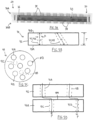
- Fig. 1A illustrates a perfusion bioreactor 10.
- the perfusion bioreactor 10 is an apparatus in which a perfusion operation is carried out.
- the perfusion bioreactor 10 (sometimes referred to herein simply as the "bioreactor 10") allows for the exchange of particles between a liquid and the cells and tissues embedded within a porous biomaterial.
- the bioreactor 10 is a vessel having a controlled environment that allows cells to survive and perform metabolic activities.
- the bioreactor 10 has agglomerations of organ cells which perform at least part of the metabolic functions of an organ of the human body.
- the bioreactor 10 may be manufactured from any suitable biocompatible plastic, metal, or composites thereof, for example polycarbonate, in order to achieve this functionality.
- the bioreactor 10 receives fluid, and conveys fluid out of the bioreactor 10.
- the bioreactor 10 therefore has a suitable inlet and a suitable outlet that are connected to suitable tubing.
- the bioreactor 10 has a housing 16 which is an elongated body extending a length L between a housing inlet 18A and a housing outlet 18B.
- the housing inlet 18A is configured to allow for infusion of plasma, nutrients, or other fluid materials into the housing 16.
- the housing 16 is a cylindrical body extending along a longitudinal axis such that it is longer than it is wide. Other shapes of the housing 16 are possible and within the scope of the present disclosure.
- the housing inlet and outlet 18A,18B are conical ends of the housing 16, and act as funnels to convey fluid into and out of the main portion of the housing 16.
- the housing 16 is hollow, and thus has an inner cavity 19 into which the fluid is conveyed for interaction with the organ cells.
- the inner cavity 19 is delimited by a wall of the housing, which is cylindrical in the depicted embodiment, and which defines an inner surface 19A. Fluid travels through the housing 16 by first entering the housing inlet 18A, then travelling through the inner cavity 19, and the exiting via the housing outlet 18B.
- the bioreactor 10 also includes perfusion devices 20.
- Each perfusion device 20 performs the work of the bioreactor 10 by assisting with the exchange of particles between a liquid and the cells and tissues embedded within a porous biomaterial of each perfusion device 20.
- the perfusion devices 20 contain the agglomeration of organ cells which perform at least part of the metabolic functions of an organ of the human body, as explained in greater detail below.
- the perfusion devices 20 are disposed in the internal cavity 19 of the housing 16. As shown in Fig. 1B , the perfusion devices 20 are disposed in the internal cavity 19 one adjacent to another and spaced apart from each other along the length L of the housing 16.
- the perfusion devices 20 form a stack of perfusion devices 20A.
- the stack of perfusion devices 20A has an upright or vertical orientation.
- the perfusion devices 20 are stacked one on top of the other in the stack of perfusion devices 20A.
- the stack of perfusion devices 20A has a horizontal or inclined orientation. Irrespective of their orientation, the perfusion devices 20 and their components interact with the fluid which travels through the inner cavity 19 of the housing 16, from the housing inlet 18A to the housing outlet 18B.
- each perfusion device 20 includes a mesh structure 30 and one or more encapsulated organ tissues 40.
- the mesh structure 30 forms the corpus of the perfusion device 20 and provides structure thereto.
- the mesh structure 30 is porous, and is supported from the inner surface 19A of the housing 16 to mount each perfusion device 20 to the housing 16.
- the encapsulated organ tissue 40 of each perfusion device is positioned within the mesh structure 30.
- the mesh structure 30 is therefore any suitable device for holding the encapsulated organ tissue 40, and for allowing the fluid within the housing 16 to engage the encapsulated organ tissue 40.
- the bioreactor 600 has a housing 616 which is an elongated body extending a length between a housing inlet 618A and a housing outlet 618B.
- the housing 616 is a cylindrical body extending along a longitudinal axis such that it is longer than it is wide.
- the housing 616 is transparent and admits light.
- the housing inlet and outlet 618A,618B are conical ends of the housing 616, and act as funnels to convey fluid into and out of the main portion of the housing 616.
- the housing 616 is hollow, and thus has an inner cavity 619 into which the fluid is conveyed for interaction with the organ cells.
- the inner cavity 619 is delimited by a transparent wall of the housing 616, which is cylindrical in the depicted embodiment. Fluid travels through the housing 616 by first entering the housing inlet 618A, then travelling through the inner cavity 619, and the exiting via the housing outlet 618B.
- the bioreactor 600 has an internal support 617 for supporting the perfusion devices 20.
- the internal support 617 is positioned within the inner cavity 619.
- the internal support 617 includes end plates 617A which are perforated to permit the passage of fluid therethrough.
- the end plates 617A are linked to each other by racks 617B which extend between the end plates 617A.
- the racks 617B are spaced apart from each other.
- the racks 617B may be attached to an internal surface of the housing 616.
- Each of the racks 617B includes notches or grooves 617C spaced apart along the length of the rack 617B.
- the mesh structure 30 of each perfusion device 20 is removably mounted to the racks 617B by being placed in the grooves 617C.
- the bioreactor 10,400 provides a controlled environment.
- the internal temperature of the bioreactor 10,400 is controlled via a heat exchanger to maintain it constant at 37oC.
- the internal pH of the bioreactor 10,400 is controlled by modulating bicarbonate to maintain it constant at about 7.4. Since the depicted bioreactor 10,400 is used to process blood plasma, erythrocytes (i.e. red blood cells) are not present in the plasma. Therefore, an oxygen content of the plasma in the bioreactor 10,400 is controlled.
- the bioreactor 10,400 may be used with other types of corporeal fluids, and may control for fewer or other parameters.
- the mesh structure 30 and the encapsulated organ tissues 40 are now described in greater detail.
- the mesh structure 30 has a first wall 32 spaced apart from a second wall 34 to define an internal mesh cavity 36.
- the encapsulated organ tissue 40 (not shown in Figs. 2A and 2B ) is disposed in the internal mesh cavity 36 between the first and second walls 32,34.
- the first and second walls 32,34 are porous to allow the fluid to enter the internal mesh cavity 36 to interact with the encapsulated organ tissue 40.
- the porous nature of the mesh structure 30 is provided by openings 38 in each of the first and second walls 32,34, which permit fluid communication through the mesh structure 30.
- the mesh structure 30 includes a base 30A and a cap 30B that is mountable on the base 30A to close the mesh structure 30 and define the internal mesh cavity 36.
- the base 30A includes the first wall 32 of the mesh structure 30, and the cap 30B includes the second wall 34.
- the cap 30B is press fit onto the base 30A.
- Fig. 3 shows a one-piece mesh structure 130.
- the mesh structure 130 is cylindrical, and is shaped as a disc.
- the first and second walls 132,134 are shown spaced apart to define the internal mesh cavity 136.
- the first and second walls 132,134 also have openings 138 therein.
- the mesh structure 130 has a side wall 131 with an aperture 133 therein.
- the aperture 133 is in fluid communication with the internal mesh cavity 136.
- the aperture 133 allows for the introduction of components making up the encapsulated organ tissue 40 into the internal mesh cavity 136, as explained in greater detail below.
- the mesh structure 30,130 may have a thickness between about 1 mm and about 8 mm, and may have a diameter between about 10 mm and about 80 mm.
- the mesh size i.e. the size of the openings 38,138
- the mesh structure 30,130 may have other shapes, including but not limited to, rectangular, square, triangular, etc.
- the encapsulated organ tissue 40 (sometimes referred to herein simply as the "EOT 40") has one or more organoids 42 that are at least partially covered with a biocompatible cross-linked polymer 44.
- Each organoid 42 is a grown or cultured mass of cells or tissue that resembles an organ.
- each organoid 42 is a liver organoid which resembles the liver, such that the EOT 40 is an encapsulated liver tissue (ELT).
- EOT 40 encapsulated liver tissue
- the fluid that enters the bioreactor 10,400 exchanges compounds with the tissue or cells of the organoids 42 within the EOT 40 so that toxic compounds are metabolized by the cells of the organoids 42 and eliminated in a non-toxic form, while useful proteins are produced by the cells of the organoids 42 and released into the fluid.
- Albumin, ammonia and other plasma constituents that need to be processed by the liver may therefore be metabolized by the liver organoids 42, which is similar to human liver function.
- the organoids 42 may also be cultured from the cells or tissues of another organ.
- a non-limitative list of other organs whose function can be mimicked by the organoids 42 includes the kidney, endocrine tissue, and any other tissue that can be perfused by blood and which can be agglomerated into organoids 42. It will therefore be appreciated that reference to the liver, liver organoids, or encapsulated liver tissue in the present disclosure does not limit the organoids 42 or the EOT 40 to only being formed from liver cells or tissue.
- Fig. 4 shows a process to provide a plurality of monodispersed liver organoids 42 within the biocompatible and crossed-linked polymer 44.
- hepatoblasts, endothelial progenitor cells and mesenchymal progenitor cells are obtained from differentiating a single iPSC.
- the cells are mixed and co-cultured in suspension to form the liver organoid 42.
- the hepatoblasts have differentiated into hepatocytes which substantially cover a cellular core formed by mesenchymal and endothelial progenitor cells (prior to the introduction of the liver organoids 42 in the encapsulated liver tissue 40).
- the embodiment of the liver organoid 42 shown in Fig. 4 is substantially spherical in shape and has a relative diameter of about 150 ⁇ m.
- the liver organoids 42 are then encapsulated, using a crosslinking agent, which in Fig. 4 is shown as UV light, in a first compatible and crosslinkable matrix.
- the encapsulated liver tissue 40 can be used as transplantable liver tissue (having for example, a size between 5 mm and 10 cm) in regenerative medicine.
- the liver organoids 42 can be designed to a multiwell plate and used in drug development to determine metabolism or hepatotoxicity of screened compounds.
- the polymer 44 (also referred to as a polymeric matrix) that can be used in the encapsulated liver tissue 40 forms a hydrogel around the liver organoids 42.
- a hydrogel refers to polymeric chains that are hydrophilic in which water is the dispersion medium. Hydrogels can be obtained from natural or synthetic polymeric networks.
- encapsulation within the hydrogel prevents embedded liver organoids 42 from leaking out of the polymer 44.
- each liver organoid 42 is encapsulated individually and the encapsulated liver organoids 42 can, in another embodiment, be further included in a polymeric matrix 44.
- the liver organoids 44 are included in a polymeric matrix 44 so as to encapsulate them. As shown in Fig.
- the liver organoids 42 encapsulated within the hydrogel material form a disc or other cylindrical structure.
- Other shapes for the organoids 42 encapsulated within the hydrogel material are possible and within the scope of the present disclosure.
- the hydrogel may be any biocompatible material. Some non-limitative examples of hydrogels include PEG, and any polyethylene glycol (PEG) based material such as PEG-vinyl sulfone (PEG-VS).
- Fig. 4 shows a process for making the encapsulated organ tissue 40, which is described in PCT patent application PCT/CA2017/051404 (published as WO 2018/094522) entitled "Encapsulated Liver Tissue” and filed November 23, 2017 , the entirety of which is incorporated by reference herein.
- the organoids 42 may be harvested from the ultra-low attachment flasks and centrifuged at low speed (400g for 5 minutes) to form a pellet.
- the pellet (about 3 000 organoids) may be resuspended in 5% 4-arm PEG-vinyl sulfone (20 kDa) solution in sterile PBS without calcium and magnesium supplemented with 0.1% N-vinyl-2-pyrrilidone and 0.4 mg/mL Irgacure 2959.
- a 50 ⁇ L droplet of such a solution (containing about 100 organoids 42) may be generated and deposed in a well of a 96-well plate, and subsequently cross-linked under UV light (5 minutes 1090 ⁇ W/cm 2 at a distance of 4 cm).
- the generated encapsulated liver tissue 40 may be maintained in complete William's E medium/complete EMB2 (1:1) medium supplemented with, 20 ng/mL OSM and 10 ⁇ M dexamethasone for 5 days. Five days after encapsulation, the OSM supplementation may be suspended and the ratio complete William's E medium/complete EBM2 medium may be changed from 1:1 to 4:1.
- the tissue may be cultured at 37°C in ambient O 2 /5%CO 2 and the medium may be changed every other day. Albumin secretion may be assessed weekly in the conditioned medium.
- encapsulated organoids 42 may preserve their ability to secrete albumin through the hydrogel over more than 7 weeks of culture, proving their survival and maintenance of their differentiated status within the polymer 44 while confirming the diffusion of the secreted protein outside of it.
- the encapsulated liver tissue 40 may be solid enough to be manipulated with instruments without losing its shape and integrity.
- Figs. 5A to 5C show one of the perfusion devices 20 and the EOT 40.
- the EOT 40 has a body 46 which provides physical structure to the EOT 40.
- the body 46 defines a thickness T.
- the thickness T is defined between a first surface 48A of the body 46 adjacent to the first wall 32 of the mesh structure 30, and a second surface 48B of the body 46 adjacent to the second wall 34.
- the EOT 40 is therefore "sandwiched" by the mesh structure 30.
- the body 46 takes the form of the mesh structure 30, and is thus shaped as a cylinder or disc.
- the body 46 may have other shapes, which are part of the present disclosure.
- the thickness T of the body 46 is between about 1 mm to about 3 mm. Other values for the thickness T of the body 46 are possible and within the scope of the present disclosure.
- the EOT 40 is a three-dimensional porous body.
- the EOT 40 is embedded with spatially-organized passages which are perfused with the fluid (e.g. plasma) supplied to the housing 16.
- the body 46 has one or more channels 41 which extend into the body 46.
- Each channel 41 extends into the body 46 from one or both or the of the first and second surfaces 48A,48B in order to receive the fluid into the channel 41.
- Each channel 41 has a diameter D. The diameter D of each channel 41 is selected so that undesirable solutes within the fluid can be diffused out of the fluid and into the surrounding tissue of the body 46 to be metabolized.
- Control over the diameter D of the channels 41 may allow for improved removal of molecules of a certain size from the fluid, while allowing molecules of interest which have different sizes to remain in the fluid.
- the diameter D of each channel 41 in the body 46 may be the same, or may vary.
- the diameter D of one or more of the channels 41 is between about 150 ⁇ m and about 750 ⁇ m. Other values for the diameter D of the channels 41 are possible and within the scope of the present disclosure.
- each EOT 40 has a vascular-like structure (i.e. the channels 41) which may assist with penetration of the fluid and its solutes within the EOT 40, and with the diffusion of solutes out of the fluid into the surrounding polymer 44 hydrogel of the body 46.
- the channels 41 may be formed using any suitable technique. Some possible techniques include photolithography, sacrificial molding, or any other suitable microfabrication technique.
- forming the channels 41 includes curing portions of the biocompatible cross-linked polymer 44 with a UV light source while the body 46 remains in the internal mesh cavity 36 of the mesh structure 30. This may include covering the body 46 with a photomask which has one or more opaque portions which correspond to the ultimate location of the channels 41.
- the biocompatible cross-linked polymer 44 is then cured with a UV light source applied to the photomask. The portions of the body 46 covered by the opaque portions of the photomask will remain uncured to thereby form the channels 41 in the body 46.
- the EOT 40 may therefore be photopolymerized within the mesh structure 30. If the channels 41 are generated while the polymer 44 is in the mesh structure 30, then the photomask used in photolithography may need to coordinate the opaque portions with the openings 38 of the mesh structure 30 to allow UV light to penetrate to the hydrogel for curing to occur.
- forming the channels 41 includes injecting the at least one liver organoid 42 and the biocompatible cross-linked polymer 44 into the internal mesh cavity 36 of the mesh structure, and then curing portions of the biocompatible cross-linked polymer 44 with a UV light source to solidify the mass.
- the portions of the polymer 44 which are not cured form the channels 41.
- One technique for achieving this result involves pipetting the hydrogel polymer 44 and the organoids 42 into the internal mesh cavity 36 via the openings 38 in the first and second walls 32,34, or via the aperture 133 (see Figs. 2A to 3 ).
- both of the first and second walls 32,34 and their openings 38 can be sealed, such as with a light-transparent seal like a glass slide.
- the mixture is then cured and photopolymerized within the mesh structure 30.
- the EOT 40 is added to the internal mesh cavity 36 of the mesh structure 30 after photopolymerization.
- the body 46 is bio-printed, or formed using a fabricated mold containing the channels 41, or by using sacrificial molding of polymers or sugars.
- the endothelial progenitor cells of the liver organoid 42 organise in a capillary or a capillary-like configuration.
- the shape, orientation, and path of the channels 41 may vary, and at least some of these are now described in greater detail.
- the body 46 includes multiple channels 41.
- the channels 41A extend through the body 46 between the first and second surfaces 48A,48B.
- the channels 41A therefore communicate the fluid through the body 46.
- a length La of the channels 41A is substantially equal to the thickness T of the body 46.
- the channels 41B also extend through the body 46, and also communicate the fluid through the body 46.
- the length Lb of the channels 41B is greater than the thickness T of the body 46 because the channels 41B are slanted or inclined with respect to the first and second surfaces 48A,48B.
- the through channels 41A,14B allow the fluid to be communicated through the body 46 of one perfusion device 20, and to the body 46A of another, immediately adjacent perfusion device 20.
- the channels 41A,41B of the body 46 are offset from the channels 41C,41D of the adjacent body 46A.
- the offset channels 41A,41B,41C,41D of the bodies 46,46A are not vertically aligned.
- the channels 41A,41B,41C,41D of the bodies 46,46A do not overlap. The fluid is therefore prevented from flowing directly, in a straight or non-deviated path, between the bodies 46,46A.
- the offset channels 41A,41B,41C,41D therefore define a winding flow path P for the fluid, such that the fluid is deviated from a straight-line path between the bodies 46,46A.
- one of the winding flow paths P allows the fluid to enter the channel 41A and flow through the body 46, and then flow along the first surface 48A of the body 46A until arriving at the channel 41C, at which point the fluid enters the channel 41C and flows through the body 46A.
- This deviation of the fluid from one perfusion device 20 to the next may help to increase the chance of solutes diffusing out of the fluid by delaying diffusion and giving the fluid more time to interact with the organoids 42 of the EOT 40.
- Fig. 6 shows another configuration of the channels 141 of the EOT 40.
- the channels 141 include a first or primary channel 141A and one or more other channels 141, referred to as secondary channels 141B.
- the primary channel 141A is a through-channel, and extends through the body 46 between the first and second surfaces 48A,48B.
- the secondary channels 141B extend into the body 46 from a first end 149A at one of the first and second surfaces 48A,48B, to a second end 149B within the body 46 at the primary channel 141A.
- the second end 149B of the secondary channels 141B opens into the primary channel 141A, such that the secondary channel 141B is in fluid communication with the primary channel 141A.
- the fluid may therefore be conveyed from the first or second surface 48A,48B of the body 46, through the secondary channels 141B, and into the primary channel 141A.
- the length La of the primary channel 141A is substantially equal to, or greater than, the thickness T of the body 46.
- the length Lb of the secondary channels 141B is either less than the thickness T of the body 46, or greater than the thickness T of the body 46.
- the length Lb' of the secondary channel 141B is less than the thickness T of the body 46.
- the length Lb" of the secondary channel 141B is greater than the thickness T of the body 46, such that this secondary channel 141B follows a meandering, winding, or serpentine path through the body 46.
- the secondary channel 141B′′′ is a "dead-end” channel, and extends into the body 46 from one of the first and second surfaces 48A,48B to a second end 149B within the body 46 that is not in fluid communication with any other channels 141A,141B.
- the dead-end secondary channel 141B′′′ may diffuse solvents out of the fluid and into the body 46.
- Fig. 7 shows another configuration of the channels 241 of the EOT 40.
- the body 46 includes two primary channels 241A.
- Each primary channel 241A extends into the body 46 from one of the first and second surfaces 48A,48B.
- Each primary channel 241A is a "dead-end" channel, and does not extend through the body 46.
- One or more secondary channels 241B extend between the two primary channels 241A to fluidly connect them. The fluid is therefore able to pass through the body 46 from each of the first and second surfaces 48A,48B by flowing into one of the primary channels 241A, through one or more secondary channels 241B, and out the other primary channel 241A.
- the fluid received at the housing inlet 18A of the housing 16 is conveyed into the internal cavity 19 to perfuse the fluid to the EOT 40 of each perfusion device 20.
- the fluid is therefore delivered through the openings 38 in the first and second walls 32,34 of each mesh structure 30 to the organoids 42 and the channels 41 of each EOT 40.
- the fluid is conveyed against gravity, from the lower housing inlet 18A to the higher housing outlet 18B.
- the housing 16 has multiple supports 17 which are attached to the inner surface 19A and spaced apart along the length L of the housing 16.
- each perfusion device 20 is removably mounted to one of the supports 17.
- the supports 17 are notches or grooves in parallel columns 17A which are attached to the inner surface 19A, and which extend along the length L of the housing 16.
- the columns 17A are supported with sieves to prevent organoids 42 from the EOT 40 from escaping into the processed fluid leaving the fluid outlet 18B in case of tissue breakage.
- Other configurations for the supports 17 are possible and within the scope of the present disclosure.
- each mesh structure 30 has one or more supports 17 for attaching to the inner surface 19A of the housing 16.
- the stack of perfusion devices 20A may be cryopreserved. All materials used may withstand extremely low temperatures without or with minimal fatigue.
- the perfusion devices 20 Prior to starting plasma therapy, the perfusion devices 20 may be taken out of cryopreservation and inserted into the bioreactor 10. Circulation of warm fluid (e.g. warm plasma) can thaw the organoids 42 in the bioreactor 10 and further maintain the temperature of the organoids 42 at body temperature, creating an optimal environment for the tissue.
- warm fluid e.g. warm plasma
- the perfusion devices 20 of the housing 16 This equates to approximately from a few million to a few billion liver cells, and may also equate to between about 500 to about 10,000 organoids per perfusion device 20.
- Fig. 8 shows an embodiment of an artificial liver system 300 having the bioreactor 10,400 described herein.
- the artificial liver system 300 helps to mimic the function of the human liver, and may therefore be referred to as a "Bio-Artificial Liver Device (BALD)".
- the artificial liver system 300 (sometimes referred to herein simply as the "system 300") includes a fluid network 302, which is a series of tubes, connectors, and other components to communicate blood plasma between the features of the system 300.
- the system 300 has a peristaltic pump 304 to circulate the plasma through the fluid network 302.
- the pump 304 pushes plasma through the fluid network 302 at a flow rate of between about 50 mL/min to about 300 mL/min.
- Infusion pumps may be placed right after the pump 304 to insert saline and/or an anticoagulant (Heparin).
- the fluid network 302 may have a pressure sensor to determine pressure across the system 300, and to ensure that plasma re-enters the patient at a pressure similar to that at which it was extracted.
- the system 300 may optionally have an adsorbent cartridge, shown in Fig. 8 as a molecular adsorbent system 306, or MAS.
- the MAS 306 is any suitable perfusion device or charcoal adsorbent system.
- the MAS 306 is in fluid communication with the fluid network 302 to remove some of the undesired solutes from the plasma.
- the undesired solutes may include toxins, and high levels of bilirubin.
- the undesired solutes are removed from the plasma in the MAS 306 using adsorption on an activated charcoal or hydrophobic resin.
- the system 300 may also have an oxygenator 308 in fluid communication with the fluid network 302, as shown in Fig. 8 .
- the oxygenator 308 operates to dissolve oxygen into the plasma to produce oxygenated plasma.
- the bioreactor 10,400 is shown in fluid communication with the oxygenator 308, and receives the oxygenated plasma therefrom.
- the oxygenated plasma enters the bioreactor 10,400 and interacts with the ELTs 40 of the perfusion devices 20, which operate to diffuse other remaining undesired solutes, not already removed by the MAS 306, out of the oxygenated plasma and into the body 46 of the EOT 40.
- the oxygenator 308 is a component of the bioreactor 10,400, and oxygenation is performed in the bioreactor 10,400 itself.
- the system 300 is free of an oxygenator.
- oxygenation is performed on the plasma downstream of the bioreactor 10,400.
- the processed plasma exiting the housing outlet 18B of the bioreactor 10,400 may be provided to attach to a commercially-available extracorporeal filtration system 310.
- the system 300 in Fig. 8 may therefore be an add-on device to be used with the existing extracorporeal filtration system 310.
- a dialyzer 416 (see Fig. 9 ) is placed in the system 300 after the bioreactor 10,400 to perform plasma dialysis.
- Fig. 9 shows another embodiment of an artificial liver system 400 having the bioreactor 10,400 described herein.
- the system 400 is a stand-alone extracorporeal unit which includes a blood circuit 401A and a plasma circuit 401B.
- the blood circuit 401A includes a pump 402 to pump blood into the system 400.
- Infusion pumps 402A are placed right after the pump 402 to insert saline and an anticoagulant (Heparin).
- the MAS 406 is positioned in the blood circuit 401A before a plasma fractionation module 408 which separates the plasma from the blood, and which provides the plasma to the plasma circuit 401B.
- the system 400 has a peristaltic pump 410 to circulate the plasma through the fluid network 412.
- a blood leak detector 414 is present before the dialyzer 416 of the plasma circuit 401B, which removes some of the undesired solutes from the plasma using a dialysate.
- the plasma circuit 401B also has an oxygenator 418 to dissolve oxygen into the plasma to produce oxygenated plasma.
- the bioreactor 10,400 is in fluid communication with the oxygenator 418, and receives the oxygenated plasma therefrom.
- the oxygenated plasma enters the bioreactor 10,400 and interacts with the ELTs 40 of the perfusion devices 20, which operate to diffuse other, remaining undesired solutes, not already removed by the MAS 406 or the dialyzer 416, out of the oxygenated plasma and into the bodies 46 of the EOTs 40.
- the processed plasma exiting the housing outlet 18B of the bioreactor 10,400 is provided back to the blood circuit 401A, where it is recombined with the separated blood products and returned to the patient's blood, or further fluid processing may be performed.
- the blood circuit 401A has an air bubble detector 420 to prevent air from being introduced into the blood.
- the system 400 may also include temperature sensor(s), flow meter(s), a cell filter(s), heat exchanger(s) to maintain a constant temperature, clamp(s), drip chamber(s), and any other suitable devices.
- Fig. 10 shows another embodiment of an artificial liver system 500 having the bioreactor 10,400 described herein.
- the system 500 is a stand-alone extracorporeal unit which includes a blood circuit 501A and a plasma circuit 501B.
- the blood circuit 501A includes a pump 502 to pump blood into the system 500.
- Infusion pumps 502A are placed right after the pump 502 to insert saline and an anticoagulant (Heparin).
- Heparin anticoagulant
- a plasma fractionation module 508 separates the plasma from the blood, and provides the plasma to the plasma circuit 501B.
- the system 500 has a peristaltic pump 510 to circulate the plasma through the fluid network 512.
- a blood leak detector 514 is present upstream of the pump 510.
- the plasma circuit 501B also has an oxygenator 518 to dissolve oxygen into the plasma to produce oxygenated plasma.
- the bioreactor 10,400 is in fluid communication with the oxygenator 518, and receives the oxygenated plasma therefrom.
- the oxygenated plasma enters the bioreactor 10,400 and interacts with the ELTs 40 of the perfusion devices 20, which operate to diffuse remaining undesired solutes out of the oxygenated plasma and into the bodies 46 of the EOTs 40.
- the processed plasma exiting the housing outlet 18B of the bioreactor 10,400 is provided back to the blood circuit 501A, and then to the dialyzer 516, which removes some of the undesired solutes from the plasma using a dialysate.
- the treated plasma is recombined with the separated blood products and returned to the patient's blood, or further fluid processing may be performed.
- the blood circuit 501A has an air bubble detector 520 to prevent air from being introduced into the blood.
- the system 500 may also include temperature sensor(s), flow meter(s), a cell filter(s), heat exchanger(s) to maintain a constant temperature, clamp(s), drip chamber(s), and any other suitable devices.
- the system 500 may include a hemoperfusion (HP) cartridge, as shown in Fig. 10 , which may be positioned upstream of the bioreactor 10,400.
- HP hemoperfusion
Landscapes
- Health & Medical Sciences (AREA)
- Life Sciences & Earth Sciences (AREA)
- Engineering & Computer Science (AREA)
- Wood Science & Technology (AREA)
- Zoology (AREA)
- Bioinformatics & Cheminformatics (AREA)
- Organic Chemistry (AREA)
- Chemical & Material Sciences (AREA)
- Biomedical Technology (AREA)
- Genetics & Genomics (AREA)
- Biotechnology (AREA)
- General Health & Medical Sciences (AREA)
- Biochemistry (AREA)
- Microbiology (AREA)
- General Engineering & Computer Science (AREA)
- Sustainable Development (AREA)
- Molecular Biology (AREA)
- Cell Biology (AREA)
- Immunology (AREA)
- Heart & Thoracic Surgery (AREA)
- Environmental Sciences (AREA)
- Dentistry (AREA)
- Gastroenterology & Hepatology (AREA)
- Hematology (AREA)
- Vascular Medicine (AREA)
- Anesthesiology (AREA)
- Biodiversity & Conservation Biology (AREA)
- Animal Behavior & Ethology (AREA)
- Public Health (AREA)
- Veterinary Medicine (AREA)
- Apparatus Associated With Microorganisms And Enzymes (AREA)
- Micro-Organisms Or Cultivation Processes Thereof (AREA)
- Prostheses (AREA)
- External Artificial Organs (AREA)
Claims (12)
- Künstliches Lebersystem (300, 400, 500), umfassend:ein Fluidnetzwerk (302, 412, 512) und eine Pumpe (304, 410, 510) zum Zirkulieren von Plasma durch das Fluidnetzwerk (302, 412, 512); undeinen Perfusionsbioreaktor (10, 600) in Fluidkommunikation mit dem Fluidnetzwerk, um das Plasma daraus zu empfangen, der Perfusionsbioreaktor (10, 600) umfassend:ein Gehäuse (16, 616) mit einer Länge (L), die zwischen einem Gehäuseeinlass (18A, 618A) und einem Gehäuseauslass (18B, 618B) definiert ist, wobei das Gehäuse (16, 616) eine innere Oberfläche (19A) aufweist, die einen inneren Hohlraum (19, 619) des Gehäuses (16, 616) zwischen dem Gehäuseeinlass (18A, 618A) und dem Gehäuseauslass (18B, 618B) begrenzt und mit diesem in Fluidkommunikation steht, wobei der Gehäuseeinlass (18A, 618A) das Plasma empfängt; undeine Vielzahl von Perfusionsvorrichtungen (20, 20A), die in dem inneren Hohlraum (19, 619) des Gehäuses (16, 616) angeordnet sind, jede der Perfusionsvorrichtungen (20, 20A) umfassend:eine Netzstruktur (30, 130), die von der inneren Oberfläche (19A) des Gehäuses (16, 616) getragen wird, wobei die Netzstruktur (30, 130) eine erste Wand (32, 132) aufweist, die von einer zweiten Wand (34, 134) beabstandet ist, um einen inneren Netzhohlraum (36, 136) zu definieren, wobei jede der ersten und zweiten Wände der Netzstruktur (30, 130) Öffnungen (38, 138) darin aufweist, um Fluidkommunikation durch die Netzstruktur (30, 130) zu ermöglichen; undein eingekapseltes Lebergewebe (40), das in dem inneren Netzhohlraum (36, 136) zwischen der ersten und zweiten Wand der Netzstruktur (30, 130) angeordnet ist, wobei das eingekapselte Lebergewebe (40) mindestens ein Leberorganoid (42) aufweist, das mindestens teilweise mit einem biokompatiblen vernetzten Polymer (44) abgedeckt ist, das eingekapselte Lebergewebe (40) einen Körper (46, 46A) mit einer Dicke (T) aufweist, die zwischen einer ersten Oberfläche (48A) des Körpers (46, 46A) angrenzend an die erste Wand (32, 132) der Netzstruktur (30, 130) und einer zweiten Oberfläche (48B) des Körpers (46, 46A) angrenzend an die zweite Wand (34, 134) der Netzstruktur (30, 130), wobei der Körper (46, 46A) mindestens einen Kanal (41, 41A, 41B, 41C, 41D, 141, 141A, 141B, 241, 241A, 241B) aufweist, der sich von einer der ersten und zweiten Oberflächen (48A, 48B) in den Körper (46, 46A) erstreckt, um das Plasma darin zu empfangen, wobei der mindestens eine Kanal (41, 41A, 41B, 41C, 41D, 141, 141A, 141B, 241, 241A, 241B) einen Durchmesser (D) aufweist, der so gewählt ist, dass unerwünschte gelöste Stoffe aus dem Plasma in den Körper (46, 46A) diffundieren;wobei die Perfusionsvorrichtungen (20, 20A) in dem inneren Hohlraum (19, 619) des Gehäuses (16, 616) nebeneinander und mit Abstand voneinander entlang der Länge (L) des Gehäuses (16, 616) angeordnet sind, um das vom Gehäuseeinlass (18A, 618A) zum Gehäuseauslass (18B, 618B) beförderte Plasma zu erhalten, und um das Plasma in das eingekapselte Lebergewebe (40) jeder Perfusionsvorrichtung (20, 20A) und in den mindestens einen Kanal (41, 41A, 41B, 41C, 41D, 141, 141A, 141B, 241, 241A, 241B) darin zu leiten.
- Künstliches Lebersystem (300, 400, 500) nach Anspruch 1, wobei sich der mindestens eine Kanal des Körpers (46, 46A) jeder Perfusionsvorrichtung (20, 20A) durch den Körper (46, 46A) zwischen der ersten und zweiten Oberfläche (48A, 48B) erstreckt.
- Künstliches Lebersystem (300, 400, 500) nach Anspruch 2, wobei eine Länge des mindestens einen Kanals im Wesentlichen gleich oder größer ist als die Dicke (T) des Körpers (46, 46A).
- Künstliches Lebersystem (300, 400, 500) nach Anspruch 2 oder 3, wobei der mindestens eine Kanal einer der Perfusionsvorrichtungen (20, 20A) gegenüber dem mindestens einen Kanal einer unmittelbar benachbarten Perfusionsvorrichtung (20, 20A) versetzt ist und das Fluid einem gewundenen Flusspfad (P) zwischen den Kanälen der benachbarten Perfusionsvorrichtungen (20, 20A) folgt.
- Künstliches Lebersystem nach Anspruch 1, wobei der mindestens eine Kanal des Körpers (46, 46A) einen ersten Kanal und mindestens einen weiteren Kanal einschließt, wobei sich der erste Kanal durch den Körper (46, 46A) zwischen der ersten und zweiten Oberfläche (48A, 48B) erstreckt, der mindestens andere Kanal sich in den Körper (46, 46A) von einem ersten Ende (149A) an einer der ersten und zweiten Oberflächen (48A, 48B) zu einem zweiten Ende (149B) innerhalb des Körpers (46, 46A) am ersten Kanal erstreckt, wobei der mindestens andere Kanal in Fluidkommunikation mit dem ersten Kanal steht.
- Künstliches Lebersystem (300, 400, 500) nach Anspruch 5, wobei eine Länge des ersten Kanals im Wesentlichen gleich oder größer ist als die Dicke (T) des Körpers (46, 46A) und eine Länge des mindestens anderen Kanals kleiner oder größer ist als die Dicke (T) des Körpers (46, 46A).
- Künstliches Lebersystem (300, 400, 500) nach Anspruch 6, wobei die Länge des mindestens einen weiteren Kanals größer ist als die Dicke (T) des Körpers (46, 46A).
- Künstliches Lebersystem (300, 400, 500) nach einem der Ansprüche 1 bis 7, umfassend eine Vielzahl von Stützen (17), die entlang der Länge (L) des Gehäuses (16, 616) voneinander beabstandet sind, wobei die Netzstruktur (30, 130) jeder Perfusionsvorrichtung (20, 20A) abnehmbar an einer der Stützen (17) montiert ist.
- Künstliches Lebersystem (300, 400, 500) nach einem der Ansprüche 1 bis 8, wobei das Gehäuse (16, 616) eine aufrechte Orientierung aufweist und die Perfusionsvorrichtungen (20, 20A) in einem Stapel übereinander vom Gehäuse (16, 616) unterstützt werden.
- Künstliches Lebersystem (300, 400, 500) nach einem der Ansprüche 1 bis 9, wobei der Durchmesser (D) des mindestens einen Kanals zwischen 150 µm und 750 µm liegt.
- Künstliches Lebersystem (300, 400, 500) nach einem der Ansprüche 1 bis 10, wobei das mindestens eine Organoid (42) des eingekapselten Lebergewebes (40) eine Vielzahl von Leberorganoiden (42) einschließt.
- Künstliches Lebersystem (300, 400, 500) nach einem der Ansprüche 1 bis 11, umfassend einen Oxygenator (308, 418, 518), der in Fluidkommunikation mit dem Fluidsystem (302, 412, 512) steht, um Sauerstoff in das Plasma zu diffundieren und sauerstoffhaltiges Plasma zu erzeugen.
Priority Applications (1)
| Application Number | Priority Date | Filing Date | Title |
|---|---|---|---|
| EP24186387.7A EP4458949A1 (de) | 2018-05-22 | 2019-05-22 | Perfusionsbioreaktor, perfusionsvorrichtung, künstliches lebersystem und zugehörige verfahren |
Applications Claiming Priority (2)
| Application Number | Priority Date | Filing Date | Title |
|---|---|---|---|
| US201862674696P | 2018-05-22 | 2018-05-22 | |
| PCT/CA2019/050698 WO2019222847A1 (en) | 2018-05-22 | 2019-05-22 | Perfusion bioreactor, perfusion device, artificial liver system, and related methods |
Related Child Applications (1)
| Application Number | Title | Priority Date | Filing Date |
|---|---|---|---|
| EP24186387.7A Division EP4458949A1 (de) | 2018-05-22 | 2019-05-22 | Perfusionsbioreaktor, perfusionsvorrichtung, künstliches lebersystem und zugehörige verfahren |
Publications (4)
| Publication Number | Publication Date |
|---|---|
| EP3797151A1 EP3797151A1 (de) | 2021-03-31 |
| EP3797151A4 EP3797151A4 (de) | 2022-04-20 |
| EP3797151B1 true EP3797151B1 (de) | 2024-08-07 |
| EP3797151C0 EP3797151C0 (de) | 2024-08-07 |
Family
ID=68616241
Family Applications (2)
| Application Number | Title | Priority Date | Filing Date |
|---|---|---|---|
| EP19808413.9A Active EP3797151B1 (de) | 2018-05-22 | 2019-05-22 | Künstliches lebersystem |
| EP24186387.7A Pending EP4458949A1 (de) | 2018-05-22 | 2019-05-22 | Perfusionsbioreaktor, perfusionsvorrichtung, künstliches lebersystem und zugehörige verfahren |
Family Applications After (1)
| Application Number | Title | Priority Date | Filing Date |
|---|---|---|---|
| EP24186387.7A Pending EP4458949A1 (de) | 2018-05-22 | 2019-05-22 | Perfusionsbioreaktor, perfusionsvorrichtung, künstliches lebersystem und zugehörige verfahren |
Country Status (9)
| Country | Link |
|---|---|
| US (2) | US11096388B2 (de) |
| EP (2) | EP3797151B1 (de) |
| JP (1) | JP2021526386A (de) |
| KR (1) | KR102768340B1 (de) |
| CN (1) | CN112154201B (de) |
| AU (1) | AU2019273870B2 (de) |
| CA (1) | CA3100865A1 (de) |
| ES (1) | ES2986823T3 (de) |
| WO (1) | WO2019222847A1 (de) |
Families Citing this family (6)
| Publication number | Priority date | Publication date | Assignee | Title |
|---|---|---|---|---|
| KR102559192B1 (ko) * | 2016-11-23 | 2023-07-27 | 몰포셀 테크놀로지스 인코포레이티드 | 캡슐화된 간 조직 |
| CN112154201B (zh) * | 2018-05-22 | 2024-12-27 | 形态细胞科技公司 | 灌注生物反应器、灌注器件、人造肝脏系统及相关方法 |
| CN111249552B (zh) * | 2020-03-16 | 2020-11-17 | 南京鼓楼医院 | 基于人iPSCs诱导类肝细胞及多层多孔生物反应器的生物人工肝 |
| WO2021260735A1 (en) * | 2020-06-26 | 2021-12-30 | Ykrita Lifesciences Private Limited | Bioengineered artificial lateral liver (ball) or bioengineered artificial ectopic liver (bael) |
| US12478723B2 (en) * | 2022-11-19 | 2025-11-25 | Ykrita Lifesciences Private Limited | Extracorporeal bioengineered dual-cell liver regeneration system (EBDLR) and bio purifier therefor |
| WO2024220607A2 (en) * | 2023-04-19 | 2024-10-24 | President And Fellows Of Harvard College | Protective mesh for tissue constructs |
Family Cites Families (28)
| Publication number | Priority date | Publication date | Assignee | Title |
|---|---|---|---|---|
| JPS53118581A (en) * | 1977-03-24 | 1978-10-17 | Kanegafuchi Chem Ind Co Ltd | Method and apparatus for culturing microorganisms |
| CN1373800A (zh) * | 1997-01-16 | 2002-10-09 | 耶路撒冷希伯来语大学依苏姆研究开发公司 | 一种进行液体的生物学改变的装置和方法 |
| JP4222658B2 (ja) * | 1998-06-23 | 2009-02-12 | テルモ株式会社 | 細胞支持基材、培養装置および液体処理装置 |
| DE60134157D1 (de) * | 2000-09-13 | 2008-07-03 | Csir Pretoria | Bioreaktor |
| JP2002335949A (ja) * | 2001-05-22 | 2002-11-26 | Inst Of Physical & Chemical Res | ハニカム構造体フィルムを用いた細胞の三次元組織培養法 |
| US20050130254A1 (en) * | 2003-12-16 | 2005-06-16 | Park Sung-Soo | Drug testing system with bio-artificial liver |
| DE10340487B4 (de) * | 2003-09-03 | 2007-07-12 | Technische Universität Dresden | Perfusionskreislauf |
| EP2061871A1 (de) * | 2006-09-14 | 2009-05-27 | ProBioGen AG | Modulares kultursystem zur haltung, differenzierung und proliferation von zellen |
| JP5583312B2 (ja) * | 2007-02-20 | 2014-09-03 | 富士フイルム株式会社 | 組織体形成用基材、組織体形成キット、それを用いた組織体形成法、及び該組織体形成法により形成された三次元組織体 |
| CN201064500Y (zh) * | 2007-08-17 | 2008-05-28 | 浙江大学 | 人工肝用填充支架灌流型生物反应器 |
| CN101199436A (zh) * | 2007-11-28 | 2008-06-18 | 中国人民解放军第三军医大学第一附属医院 | 三维立体式培养肝细胞的生物反应器 |
| CN201211251Y (zh) * | 2008-07-04 | 2009-03-25 | 南京大学医学院附属鼓楼医院 | 新型生物人工肝细胞反应器 |
| EP2344622B1 (de) * | 2008-10-08 | 2017-12-20 | Agency for Science, Technology And Research | Vorrichtung zur kultivierung verankerungsabhängiger zellen |
| CN201418905Y (zh) * | 2009-05-07 | 2010-03-10 | 浙江大学 | 人工肝用纤维网片叠加式生物反应器 |
| CN102198022B (zh) * | 2011-05-23 | 2013-04-17 | 西安交通大学 | 一种活性细胞-水凝胶类器官结构体的立体成形方法 |
| SG10201805199RA (en) * | 2011-06-02 | 2018-07-30 | Harvard College | Methods and Uses for Ex Vivo Tissue Culture Systems |
| WO2013086486A1 (en) * | 2011-12-09 | 2013-06-13 | President And Fellows Of Harvard College | Integrated human organ-on-chip microphysiological systems |
| CN102631710A (zh) * | 2012-04-13 | 2012-08-15 | 清华大学 | 多通道多层细胞结构的复合组织器官前体的制备方法 |
| JP6396909B2 (ja) * | 2012-09-29 | 2018-09-26 | ノーティス,インク. | インビトロで組織及び器官の機能単位を再現するためのマイクロ流体システム |
| CN103100119A (zh) * | 2013-01-24 | 2013-05-15 | 中山大学 | 一种人工肝生物反应器 |
| CN106163581B (zh) * | 2013-11-05 | 2019-10-25 | 哈佛学院院长及董事 | 打印具有包埋的脉管系统的组织构建体的方法 |
| US9701933B2 (en) * | 2014-09-19 | 2017-07-11 | Sarfaraz K. Niazi | Harvesting and purification or perfusion yielder (HAPPY) device |
| CN107427537A (zh) * | 2015-03-03 | 2017-12-01 | 哈佛学院院长及董事 | 产生功能性人体组织的方法 |
| JP7005018B2 (ja) * | 2015-10-02 | 2022-02-04 | ウェイク・フォレスト・ユニヴァーシティ・ヘルス・サイエンシズ | 自発拍動心臓オルガノイド構築物およびそれを含む統合ボディ・オン・チップ装置 |
| JP6942448B2 (ja) * | 2016-08-08 | 2021-09-29 | 株式会社カネカ | 細胞培養容器、これを用いた細胞培養システム、および細胞培養方法 |
| KR102559192B1 (ko) | 2016-11-23 | 2023-07-27 | 몰포셀 테크놀로지스 인코포레이티드 | 캡슐화된 간 조직 |
| CN112154201B (zh) * | 2018-05-22 | 2024-12-27 | 形态细胞科技公司 | 灌注生物反应器、灌注器件、人造肝脏系统及相关方法 |
| EP4426752A1 (de) * | 2021-11-01 | 2024-09-11 | Universiteit Maastricht | Hydrogele für organoide kultur |
-
2019
- 2019-05-22 CN CN201980033743.XA patent/CN112154201B/zh active Active
- 2019-05-22 EP EP19808413.9A patent/EP3797151B1/de active Active
- 2019-05-22 ES ES19808413T patent/ES2986823T3/es active Active
- 2019-05-22 WO PCT/CA2019/050698 patent/WO2019222847A1/en not_active Ceased
- 2019-05-22 EP EP24186387.7A patent/EP4458949A1/de active Pending
- 2019-05-22 AU AU2019273870A patent/AU2019273870B2/en active Active
- 2019-05-22 US US17/057,061 patent/US11096388B2/en active Active
- 2019-05-22 KR KR1020207036834A patent/KR102768340B1/ko active Active
- 2019-05-22 JP JP2021515255A patent/JP2021526386A/ja active Pending
- 2019-05-22 CA CA3100865A patent/CA3100865A1/en active Pending
-
2021
- 2021-07-16 US US17/377,574 patent/US11805775B2/en active Active
Also Published As
| Publication number | Publication date |
|---|---|
| US11805775B2 (en) | 2023-11-07 |
| KR20210011996A (ko) | 2021-02-02 |
| CA3100865A1 (en) | 2019-11-28 |
| AU2019273870A1 (en) | 2021-01-21 |
| EP3797151A1 (de) | 2021-03-31 |
| KR102768340B1 (ko) | 2025-02-17 |
| US20210337783A1 (en) | 2021-11-04 |
| AU2019273870B2 (en) | 2024-12-12 |
| US20210176984A1 (en) | 2021-06-17 |
| WO2019222847A1 (en) | 2019-11-28 |
| EP4458949A1 (de) | 2024-11-06 |
| CN112154201A (zh) | 2020-12-29 |
| JP2021526386A (ja) | 2021-10-07 |
| EP3797151A4 (de) | 2022-04-20 |
| EP3797151C0 (de) | 2024-08-07 |
| ES2986823T3 (es) | 2024-11-12 |
| US11096388B2 (en) | 2021-08-24 |
| CN112154201B (zh) | 2024-12-27 |
Similar Documents
| Publication | Publication Date | Title |
|---|---|---|
| EP3797151B1 (de) | Künstliches lebersystem | |
| US11596901B2 (en) | Biomimetically designed modular microfluidic-based capillaries and lymphatic units for kidney and liver dialysis systems, organ bio-reactors and bio-artificial organ support systems | |
| AU748044B2 (en) | A device and method for performing a biological modification of a fluid | |
| US8491561B2 (en) | Micromachined bilayer unit of engineered tissues | |
| JP5524824B2 (ja) | 改良されたバイオリアクタ表面 | |
| CA2262812C (en) | Hollow fiber bioreactor comprising a hydrogel flow restrictor | |
| US9095817B2 (en) | Device for the treatment of biological fluid | |
| US6858146B1 (en) | Artificial liver apparatus and method | |
| EP1196029A2 (de) | Vorrichtung und verfahren zur durchführung einer biologischen modifizierung einer flüssigkeit | |
| JP2003206201A (ja) | 臓器収納装置を含む移植用臓器保存装置および該収納装置を含む人工臓器システム | |
| CN106659834B (zh) | 用于去除血液中的促炎介质以及粒细胞和单核细胞的系统 | |
| JP2004275718A (ja) | バイオ人工膵臓用モジュール及びバイオ人工膵臓 | |
| JP2004041527A (ja) | バイオ人工臓器 | |
| CA2201159A1 (en) | Artificial liver apparatus and method | |
| JP2004049301A (ja) | 血液浄化装置 | |
| EP2444478A1 (de) | Röhrenförmiges Körperflüssigkeitsmassenaustauschsystem und Massenaustauschvorrichtung |
Legal Events
| Date | Code | Title | Description |
|---|---|---|---|
| STAA | Information on the status of an ep patent application or granted ep patent |
Free format text: STATUS: THE INTERNATIONAL PUBLICATION HAS BEEN MADE |
|
| PUAI | Public reference made under article 153(3) epc to a published international application that has entered the european phase |
Free format text: ORIGINAL CODE: 0009012 |
|
| STAA | Information on the status of an ep patent application or granted ep patent |
Free format text: STATUS: REQUEST FOR EXAMINATION WAS MADE |
|
| 17P | Request for examination filed |
Effective date: 20201217 |
|
| AK | Designated contracting states |
Kind code of ref document: A1 Designated state(s): AL AT BE BG CH CY CZ DE DK EE ES FI FR GB GR HR HU IE IS IT LI LT LU LV MC MK MT NL NO PL PT RO RS SE SI SK SM TR |
|
| AX | Request for extension of the european patent |
Extension state: BA ME |
|
| DAV | Request for validation of the european patent (deleted) | ||
| DAX | Request for extension of the european patent (deleted) | ||
| A4 | Supplementary search report drawn up and despatched |
Effective date: 20220322 |
|
| RIC1 | Information provided on ipc code assigned before grant |
Ipc: C12M 1/12 20060101ALI20220316BHEP Ipc: C12M 1/00 20060101ALI20220316BHEP Ipc: C12N 5/07 20100101ALI20220316BHEP Ipc: A61M 1/34 20060101ALI20220316BHEP Ipc: C12M 3/00 20060101AFI20220316BHEP |
|
| GRAP | Despatch of communication of intention to grant a patent |
Free format text: ORIGINAL CODE: EPIDOSNIGR1 |
|
| STAA | Information on the status of an ep patent application or granted ep patent |
Free format text: STATUS: GRANT OF PATENT IS INTENDED |
|
| INTG | Intention to grant announced |
Effective date: 20240305 |
|
| GRAS | Grant fee paid |
Free format text: ORIGINAL CODE: EPIDOSNIGR3 |
|
| GRAA | (expected) grant |
Free format text: ORIGINAL CODE: 0009210 |
|
| STAA | Information on the status of an ep patent application or granted ep patent |
Free format text: STATUS: THE PATENT HAS BEEN GRANTED |
|
| AK | Designated contracting states |
Kind code of ref document: B1 Designated state(s): AL AT BE BG CH CY CZ DE DK EE ES FI FR GB GR HR HU IE IS IT LI LT LU LV MC MK MT NL NO PL PT RO RS SE SI SK SM TR |
|
| REG | Reference to a national code |
Ref country code: GB Ref legal event code: FG4D |
|
| REG | Reference to a national code |
Ref country code: CH Ref legal event code: EP |
|
| REG | Reference to a national code |
Ref country code: IE Ref legal event code: FG4D |
|
| REG | Reference to a national code |
Ref country code: DE Ref legal event code: R096 Ref document number: 602019056663 Country of ref document: DE |
|
| U01 | Request for unitary effect filed |
Effective date: 20240809 |
|
| U07 | Unitary effect registered |
Designated state(s): AT BE BG DE DK EE FI FR IT LT LU LV MT NL PT RO SE SI Effective date: 20240902 |
|
| REG | Reference to a national code |
Ref country code: ES Ref legal event code: FG2A Ref document number: 2986823 Country of ref document: ES Kind code of ref document: T3 Effective date: 20241112 |
|
| PG25 | Lapsed in a contracting state [announced via postgrant information from national office to epo] |
Ref country code: PL Free format text: LAPSE BECAUSE OF FAILURE TO SUBMIT A TRANSLATION OF THE DESCRIPTION OR TO PAY THE FEE WITHIN THE PRESCRIBED TIME-LIMIT Effective date: 20240807 Ref country code: GR Free format text: LAPSE BECAUSE OF FAILURE TO SUBMIT A TRANSLATION OF THE DESCRIPTION OR TO PAY THE FEE WITHIN THE PRESCRIBED TIME-LIMIT Effective date: 20241108 |
|
| PG25 | Lapsed in a contracting state [announced via postgrant information from national office to epo] |
Ref country code: IS Free format text: LAPSE BECAUSE OF FAILURE TO SUBMIT A TRANSLATION OF THE DESCRIPTION OR TO PAY THE FEE WITHIN THE PRESCRIBED TIME-LIMIT Effective date: 20241207 |
|
| PG25 | Lapsed in a contracting state [announced via postgrant information from national office to epo] |
Ref country code: HR Free format text: LAPSE BECAUSE OF FAILURE TO SUBMIT A TRANSLATION OF THE DESCRIPTION OR TO PAY THE FEE WITHIN THE PRESCRIBED TIME-LIMIT Effective date: 20240807 |
|
| PG25 | Lapsed in a contracting state [announced via postgrant information from national office to epo] |
Ref country code: RS Free format text: LAPSE BECAUSE OF FAILURE TO SUBMIT A TRANSLATION OF THE DESCRIPTION OR TO PAY THE FEE WITHIN THE PRESCRIBED TIME-LIMIT Effective date: 20241107 |
|
| PG25 | Lapsed in a contracting state [announced via postgrant information from national office to epo] |
Ref country code: RS Free format text: LAPSE BECAUSE OF FAILURE TO SUBMIT A TRANSLATION OF THE DESCRIPTION OR TO PAY THE FEE WITHIN THE PRESCRIBED TIME-LIMIT Effective date: 20241107 Ref country code: PL Free format text: LAPSE BECAUSE OF FAILURE TO SUBMIT A TRANSLATION OF THE DESCRIPTION OR TO PAY THE FEE WITHIN THE PRESCRIBED TIME-LIMIT Effective date: 20240807 Ref country code: IS Free format text: LAPSE BECAUSE OF FAILURE TO SUBMIT A TRANSLATION OF THE DESCRIPTION OR TO PAY THE FEE WITHIN THE PRESCRIBED TIME-LIMIT Effective date: 20241207 Ref country code: HR Free format text: LAPSE BECAUSE OF FAILURE TO SUBMIT A TRANSLATION OF THE DESCRIPTION OR TO PAY THE FEE WITHIN THE PRESCRIBED TIME-LIMIT Effective date: 20240807 Ref country code: GR Free format text: LAPSE BECAUSE OF FAILURE TO SUBMIT A TRANSLATION OF THE DESCRIPTION OR TO PAY THE FEE WITHIN THE PRESCRIBED TIME-LIMIT Effective date: 20241108 |
|
| PG25 | Lapsed in a contracting state [announced via postgrant information from national office to epo] |
Ref country code: SM Free format text: LAPSE BECAUSE OF FAILURE TO SUBMIT A TRANSLATION OF THE DESCRIPTION OR TO PAY THE FEE WITHIN THE PRESCRIBED TIME-LIMIT Effective date: 20240807 |
|
| PG25 | Lapsed in a contracting state [announced via postgrant information from national office to epo] |
Ref country code: CZ Free format text: LAPSE BECAUSE OF FAILURE TO SUBMIT A TRANSLATION OF THE DESCRIPTION OR TO PAY THE FEE WITHIN THE PRESCRIBED TIME-LIMIT Effective date: 20240807 |
|
| PG25 | Lapsed in a contracting state [announced via postgrant information from national office to epo] |
Ref country code: SK Free format text: LAPSE BECAUSE OF FAILURE TO SUBMIT A TRANSLATION OF THE DESCRIPTION OR TO PAY THE FEE WITHIN THE PRESCRIBED TIME-LIMIT Effective date: 20240807 |
|
| PLBE | No opposition filed within time limit |
Free format text: ORIGINAL CODE: 0009261 |
|
| STAA | Information on the status of an ep patent application or granted ep patent |
Free format text: STATUS: NO OPPOSITION FILED WITHIN TIME LIMIT |
|
| PGFP | Annual fee paid to national office [announced via postgrant information from national office to epo] |
Ref country code: GB Payment date: 20250515 Year of fee payment: 7 Ref country code: ES Payment date: 20250606 Year of fee payment: 7 |
|
| PGFP | Annual fee paid to national office [announced via postgrant information from national office to epo] |
Ref country code: NO Payment date: 20250528 Year of fee payment: 7 |
|
| 26N | No opposition filed |
Effective date: 20250508 |
|
| U21 | Renewal fee for the european patent with unitary effect paid with additional fee |
Year of fee payment: 7 Effective date: 20250725 |