EP3791701B1 - Rack sowie server- oder netzwerkschrank mit einem rack - Google Patents
Rack sowie server- oder netzwerkschrank mit einem rack Download PDFInfo
- Publication number
- EP3791701B1 EP3791701B1 EP19711595.9A EP19711595A EP3791701B1 EP 3791701 B1 EP3791701 B1 EP 3791701B1 EP 19711595 A EP19711595 A EP 19711595A EP 3791701 B1 EP3791701 B1 EP 3791701B1
- Authority
- EP
- European Patent Office
- Prior art keywords
- rack
- longitudinal profiles
- positioning arrangement
- longitudinal
- another
- Prior art date
- Legal status (The legal status is an assumption and is not a legal conclusion. Google has not performed a legal analysis and makes no representation as to the accuracy of the status listed.)
- Active
Links
Images





Classifications
-
- H—ELECTRICITY
- H05—ELECTRIC TECHNIQUES NOT OTHERWISE PROVIDED FOR
- H05K—PRINTED CIRCUITS; CASINGS OR CONSTRUCTIONAL DETAILS OF ELECTRIC APPARATUS; MANUFACTURE OF ASSEMBLAGES OF ELECTRICAL COMPONENTS
- H05K7/00—Constructional details common to different types of electric apparatus
- H05K7/14—Mounting supporting structure in casing or on frame or rack
- H05K7/1485—Servers; Data center rooms, e.g. 19-inch computer racks
- H05K7/1488—Cabinets therefor, e.g. chassis or racks or mechanical interfaces between blades and support structures
Definitions
- the invention relates to a rack, in particular a server rack or network rack, according to the preamble of claim 1. Furthermore, the invention relates to a server or network cabinet with such a rack with the features in claim 7.
- a server rack that comprises a frame with four longitudinal profiles arranged opposite one another.
- the longitudinal profiles form an interior space between them, so that the external dimensions of the server rack are essentially determined by the position of the longitudinal profiles in relation to one another.
- the EP 2 796 121 A1 discloses a wheelchair whose base frame comprises two side frames arranged parallel to one another with essentially horizontally and vertically oriented tubes.
- the side frames are coupled to one another via a positioning arrangement which has a scissor element and a folding hinge.
- the positioning arrangement is designed to be movable in such a way that the two side frames can be displaced relative to one another.
- the present invention is therefore based on the object of further developing the base frame known in connection with the wheelchair in order to expand its area of application in relation to a rack.
- this object is achieved in a rack with the features of claim 1.
- Advantageous embodiments are the subject of the dependent subclaims 2 to 6.
- the invention is achieved by a server or network cabinet with the features of claim 7.
- the core of the invention is a connection of the main components of the rack that is as mobile as possible, through whose structural linkage the essential connections are always active, while the mobility enables compact folding and then rapid unfolding into the usable state.
- the invention provides that the four longitudinal profiles of the frame are connected to one another via a correspondingly mobile positioning arrangement. This makes it possible to move the longitudinal profiles connected to the positioning arrangement relative to one another. In this way, they can be brought closer together without the need for disassembly, for example for transport, in order to minimize the external dimensions of the rack. On site, the longitudinal profiles can then be moved into their intended positions almost without tools. so that the stable basic shape of the frame is restored within a very short time.
- the positioning arrangement comprises two rods spaced apart from one another.
- the first rod is connected to the end sections of the longitudinal profiles that are aligned in one direction and are located at a first end of the frame.
- the end sections of the longitudinal profiles that are opposite the first end and are therefore located at the second end are connected to the second rod.
- the longitudinal profiles and the rods thus limit the interior space that stretches between them and is therefore advantageously undisturbed for accommodating any devices and components.
- Each rod of the positioning arrangement has a cross-section and at least one boom pivotably arranged on a section of the cross-section.
- the free ends of the cross-section and the boom are each connected to the associated end section of a longitudinal profile.
- each of these connections can be designed to be rigid in order to directly establish the stability of the frame.
- the boom can advantageously be pivotably arranged on a middle section of the cross-section in order to enable unhindered pivoting. In addition, this results in the shortest length for the boom in order to position the longitudinal profile connected to it in the associated corner point of a frame that has a rectangular cross-section when in use. In addition to an increased This stability also allows for the lowest possible weight.
- two outriggers are arranged on each cross profile of the two rods in a pivotable manner.
- the outriggers can be arranged offset from one another on a central section of the corresponding cross profile.
- Two of the longitudinal profiles which are arranged diagonally opposite one another at a fixed distance, are connected to the free ends of the cross profile of each rod, while the other two longitudinal profiles are each connected to the free end of the corresponding outrigger of each rod.
- the longitudinal profiles connected to the cross profiles are always firmly positioned relative to one another, with the other two longitudinal profiles being able to be moved accordingly via the pivoting outriggers. This allows the rack to be transported in an extremely flat state by moving the pivoting longitudinal profiles as close as possible to one of the other two longitudinal profiles.
- At least part of the positioning arrangement can be designed to be pivotable transversely to the longitudinal direction of at least one longitudinal profile. This allows the spatial arrangement of the longitudinal profiles to be changed in a simple manner by pivoting in order to transfer the rack in terms of its external dimensions from a use state to a smaller transport state and back again.
- the invention provides an additional arrangement located inside the rack, which serves to actually hold devices or assemblies.
- two inner frames designed to hold inserts are proposed for this purpose, which are attached to the positioning arrangement.
- the inner frames can also have a differently designed grid in order to correspond to the standardized holding of devices or assemblies.
- Each of these inner frames has two posts and two bars connecting the posts to one another.
- the inner frames can be attached to the positioning arrangement in a pivotable manner in order to support the compact folding of the rack into its transport state.
- the inner frames can be designed and arranged such that they extend between two spaced-apart rods of the positioning arrangement.
- the inner frames are coupled or can be coupled with gusset plates arranged between the positioning arrangement and each longitudinal profile.
- the gusset plates can be arranged between a longitudinal profile and a boom or cross profile connected to it. the positioning arrangement, which results in a high stability for the frame.
- the longitudinal profiles are connected to the positioning arrangement in a rotationally fixed manner. This further increases stability, while the necessary mobility of the positioning unit is preferably limited only to the articulated connection of the arms arranged on the cross members of the positioning arrangement.
- the rack according to the invention now presented enables it to be folded up into a transport state extremely easily, while it can be easily put into its usable state on site within a very short time.
- the invention is further directed to a server or network cabinet which contains a rack according to the invention as described above. Furthermore, at least one wall element and/or door element is provided, by which the rack is at least partially covered.
- the at least partial cladding of the rack protects the devices and components that can be arranged therein from accidental or unauthorized access as well as damage and contamination.
- Overall The overall visual impression can be improved, for example by covering connecting cables.
- the lockable version of the door element in particular allows for effective access control.
- Fig.1 shows a perspective view of a rack 1 according to the invention in its use state A.
- the rack 1 is designed to accommodate devices and/or assemblies not shown in detail here
- the rack 1 is designed to be foldable so that it can be changed between the use state A and a transport state B which is smaller in size (cf. Fig.7 ).
- the rack 1 comprises a frame 2, which in the present case has four longitudinal profiles 3-6 arranged opposite one another in the use state A shown here.
- An imaginary casing of the longitudinal profiles 3-6 essentially determines the external dimensions of the frame 2 and thus of the rack 1.
- the longitudinal profiles 3-6 are connected to one another via a positioning arrangement 7, via which they are positioned and aligned with one another.
- the longitudinal profiles 3-6 are connected to the positioning arrangement 7 in a rotationally fixed manner. It can be seen that the respective longitudinal directions x1-x4 of the longitudinal profiles 3-6 run parallel to one another.
- the positioning device 7 has two rods 8, 9 connected to the longitudinal profiles 3-6.
- the first rod 8 is connected to end sections 3a-6a of the longitudinal profiles 3-6 located at a first end E1 of the frame 2.
- the second rod 9 is connected to end sections 3b-6b of the longitudinal profiles 3-6 located at a second end E2 opposite the first end E1.
- the two frames 8, 9 each extend in the plane the two ends E1, E2 of the frame 2, so that they are spaced apart from one another, forming an interior space 10 of the rack 1 between them and the longitudinal profiles 3-6.
- the rack 1 also has two inner frames 11, 12 intended to accommodate inserts (not shown in detail here), which are pivotally attached to the positioning arrangement 7.
- the inner frames 11, 12 extend between the two rods 8, 9 of the positioning arrangement 7.
- a gusset plate (not shown in detail here) can be arranged, wherein the inner frames 11, 12 can each be coupled or can be coupled to two of these gussets.
- Each inner frame 11, 12 has two posts 11a, 11b running parallel to the longitudinal directions x1-x4 of the longitudinal profiles 3-6; 12a, 12b, which are each connected to one another by two bars 11c, 11d; 12c, 12d running transversely thereto.
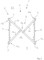
- Fig.2 shows rack 1 from Fig.1 in a supervision of the with reference to the representation of Fig.1 top-located first end E1.
- the further explanations for the first rod 8 shown here apply to the second rod 9 accordingly.
- the rod 8 has a cross-section 13 extending between two of the diagonally opposite longitudinal profiles 4, 6, on the middle section 13a of which two mutually offset arms 14, 15 are pivotably arranged.
- the free ends 13b, 13c of the cross-section 13 are connected to the associated longitudinal profiles 4, 6 in a rigid and torsion-proof manner, whereby these are in are positioned at a fixed distance from each other.
- the two remaining longitudinal profiles 3, 5 are each connected to a free end 14a, 15a of the booms 14, 15 in a rigid and torsion-proof manner.
- the longitudinal profiles 3-6 connected to it can be displaced relative to each other in that the longitudinal profiles 3, 5 connected to the booms 14, 15, which can be pivoted transversely to the longitudinal directions x1-x4, can be changed in their respective positions.
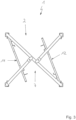
- Fig.3 the beginning of the transfer of the rack 1 from its use state A to its transport state B can be seen. It is clear that the two inner frames 11, 12 have already been pivoted a little way into the interior 10 of the rack 1. The positioning arrangement 7 of the frame 2 still shows the previous alignment of its parts.
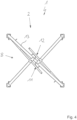
- Fig.4 shows the fully folded state of the inner frames 11, 12. It can be seen that these run almost parallel to the cross profile 13 of the rod 8.
- Fig.6 illustrates the transport state B of the rack 1, in which the two inner frames 11, 12 and the two outriggers 14, 15 together with the longitudinal profiles 3, 5 are completely folded in by swiveling. It can be seen that the external dimensions of the frame 2 and thus of the rack 1 are now significantly reduced compared to the state of use A. To assemble the rack 1, the steps described above are carried out in the reverse order.
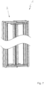
- Fig.7 shows the rack 1 again in perspective view in transport state B.
- the rack 1 By covering the rack 1 in a manner not shown in detail here with at least one wall element and/or door element, it can be expanded into a server or network cabinet according to the invention.
- Fig.8 shows a first alternative embodiment of the rack 1 according to the invention in a top view of the frame 8.
- the statements made for the first rod 8 visible in each case also apply to this and the alternative embodiments explained in more detail below for the - concealed and therefore not visible - second rod 9 accordingly.
- the individual Racks 1 may or may not have inner frames 11, 12 (not shown in detail), whereby in the absence of inner frames 11, 12 the longitudinal profiles 3-6 themselves may also have means for holding devices or components (not shown in detail).
- the curved arrows represent the possible pivoting direction of parts of the respective rack 1.
- the straight arrow between these representations illustrates the change described in each case from the use state A to the transport state B, whereby the transport state B adopted can be changed back to the use state A by reversing it and correspondingly opposite pivoting directions.
- the frame 8 of the first variant of the rack 1 has a positioning arrangement 7 in which the two arms 14, 15 are arranged in an articulated manner in the area of the free ends 13b, 13c of the cross profile 13.
- the arms 14, 15 together with the cross profile 13 form a Z-shape in the top view shown here.
- the arms 14, 15 are designed to be correspondingly longer in order to position the longitudinal profiles 3-6 in the use state A in the corner points of the frame 2, which has a rectangular cross section.
- Fig.9 a second alternative embodiment of the rack 1 according to the invention can be seen in a top view of the frame 8.
- the rod 8 has only a single arm 14, which is articulated in the middle section 13a of the cross profile 13 is arranged on it.
- the Y-shape of the frame 2 which appears in the top view, therefore requires only three longitudinal profiles 3-5.
- the positions indicated with broken lines illustrate alternative positions of the cross profile 13 or the boom 14.
- This variant is the only one in which any devices or modules can only be inserted into and removed from the rack 1 from one side, while the other variants allow access from two opposite sides.
- Fig.10 discloses a third alternative design of the rack 1 according to the invention in a top view of the frame 8.
- This comprises a total of four arms 14, 14b; 15, 14b, which are each arranged in pairs in an articulated manner in the area of the two free ends 13b, 13c of the cross profile 13.
- the arms 14, 14b; 15, 14b can have the shortest design in order to position the longitudinal profiles 3-6 in the corner points of the frame 2, which has a rectangular cross section.
- Fig. 11 corresponds essentially to the design of the rack 1 according to the invention described at the beginning in a plan view of the frame 8.
- the two arms 14, 15 are located virtually opposite one another and thus not offset from one another on the middle section 13a of the cross profile 13 and are connected to it in an articulated manner.
Landscapes
- Engineering & Computer Science (AREA)
- Computer Hardware Design (AREA)
- General Engineering & Computer Science (AREA)
- Microelectronics & Electronic Packaging (AREA)
- Warehouses Or Storage Devices (AREA)
- Assembled Shelves (AREA)
Description
- Die Erfindung betrifft ein Rack, insbesondere Serverrack oder Netzwerkrack, gemäß dem Oberbegriff von Anspruch 1. Weiterhin betrifft die Erfindung einen Server- oder Netzwerkschrank mit einem solchen Rack mit den Merkmalen in Anspruch 7.
- Miteinander zusammenarbeitende oder thematisch zusammengehörige Geräte und Baugruppen werden üblicherweise zu einer Einheit zusammengefasst. Neben der so eindeutigeren Zuordnung sowie Verkürzung von Verbindungswegen erleichtert dies zudem den Transport. Hierfür haben sich standardisierte Aufbewahrungssysteme etabliert, deren Regalform ein genormtes Aufnahmeraster für die einzelne Geräte und Baugruppen enthält. Offene Ausgestaltungen sind unter dem Begriff "Rack" geläufig, während dessen zumindest bereichsweise Verkleidung mit Tür- oder Wandelementen als Schrank bezeichnet wird. Typische Anwendungsbereiche finden sich beispielsweise in Rechenzentren sowie Labors und Studios, wobei deren jeweiliger Inhalt von Teilen der Netzwerk- und Regeltechnik bis hin zur Musik- und Veranstaltungstechnik reicht. Dabei haben sich im Wesentlichen 19-Zoll-Systeme durchgesetzt, die der Aufnahme von Geräten oder Baugruppen mit einer normierten Breite von 19 Zoll dienen.
- Aus
DE 10 2015 120 944 A1 geht ein Server-Rack hervor, welches ein Gestell mit vier gegenüberliegend angeordneten Längsprofilen umfasst. Die Längsprofile spannen einen Innenraum zwischen sich auf, so dass die äußeren Abmessungen des Server-Racks im Wesentlichen durch die Position der Längsprofile zueinander bestimmt sind. - Die
EP 2 796 121 A1 offenbart einen Rollstuhl, dessen Grundgestell zwei parallel zueinander angeordnete Seitenrahmen mit im Wesentlichen horizontal sowie vertikal orientierten Rohren umfasst. Die Seitenrahmen sind über eine Positionieranordnung miteinander gekoppelt, welche ein Scherenelement und ein Faltscharnier aufweist. Um das Grundgestell möglichst platzsparend zusammenfalten zu können, ist die Positionieranordnung derart beweglich ausgebildet, dass die beiden Seitenrahmen relativ zueinander verlagerbar sind. - Der Transport inhaltsloser Racks beziehungsweise entsprechender Schränke kann montiert oder demontiert erfolgen. Der an sich vorteilhafte, da handlichere und insofern weniger platzintensive Transport im zerlegten Zustand erfordert den anschließenden Zusammenbau vor Ort. Neben dem hierfür notwendigen Geschick sowie dem Vorhalten entsprechender Werkzeuge gestaltet sich dies bisweilen aufwendig und zeitintensiv; etwaige Fehler beim Zusammenbau durch Privatleute oder ungeschultes Personal sind dabei nicht ausgeschlossen.
- Der vorliegenden Erfindung liegt daher die Aufgabe zugrunde, das im Zusammenhang mit dem Rollstuhl bekannte Grundgestellt weiterzuentwickeln, um dessen Anwendungsbereich in Bezug auf ein Rack zu erweitern.
- Die Lösung dieser Aufgabe besteht nach der Erfindung in einem Rack mit den Merkmalen von Anspruch 1. Vorteilhafte Ausgestaltungen sind Gegenstand der abhängigen Unteransprüche 2 bis 6. Weiterhin wird die Erfindung durch einen Server- oder Netzwerkschrank, mit den Merkmalen von Anspruch 7 gelöst.
- Kern der Erfindung ist eine möglichst bewegliche Verbindung der hauptsächlichen Bestandteile des Racks, durch deren bauliche Verkettung die wesentlichen Verbindungen stets aktiv sind, während die Beweglichkeit ein kompaktes Zusammenlegen und anschließend schnelles Entfalten in den Gebrauchszustand ermöglicht. Hierzu sieht die Erfindung vor, dass die vier Längsprofile des Gestells über eine entsprechend beweglich ausgebildete Positionieranordnung miteinander verbunden sind. Damit ist es möglich, die mit der Positionieranordnung verbundenen Längsprofile relativ zueinander zu verlagern. Auf diese Weise können diese ohne die Notwendigkeit einer Demontage beispielsweise für den Transport einander angenähert werden, um die äußeren Abmessungen des Racks zu minimieren. Vor Ort können die Längsprofile dann quasi werkzeuglos in ihre vorgesehenen Positionen bewegt werden, so dass innerhalb kürzester Zeit die stabile Grundform des Gestells wiederhergestellt ist.
- Hierzu umfasst die Positionieranordnung zwei zueinander beabstandete Gestänge. Dabei ist das erste Gestänge mit den zu einer Richtung hin ausgerichteten Endabschnitten der Längsprofile verbunden, die an einem ersten Ende des Gestells gelegen sind. Demgegenüber sind die dem ersten Ende gegenüberliegenden und insofern am zweiten Ende gelegenen Endabschnitte der Längsprofile mit dem zweiten Gestänge verbunden. Damit begrenzen die Längsprofile und die Gestänge den sich zwischen diesen aufspannenden und damit in vorteilhafter Weise ungestörten Innenraum zur Aufnahme etwaiger Geräte und Baugruppen.
- Jedes Gestänge der Positionieranordnung besitzt ein Querprofil und wenigstens einen schwenkbar an einem Abschnitt des Querprofils angeordneten Ausleger. Die freien Enden des Querprofils und des Auslegers sind dabei jeweils mit dem zugehörigen Endabschnitt eines Längsprofils verbunden. Besonders bevorzugt kann jede dieser Verbindungen biegesteif ausgeführt sein, um direkt die Stabilität des Gestells zu begründen. In vorteilhafter Weise kann der Ausleger an einem mittleren Abschnitt des Querprofils schwenkbar angeordnet sein, um eine ungestörte Schwenkbarkeit zu ermöglichen. Überdies ergibt sich so die kürzeste Länge für den Ausleger, um das damit verbundene Längsprofil im zugehörigen Eckpunkt eines im Gebrauchszustand im Querschnitt rechteckigen Gestells zu positionieren. Neben einer erhöhten Stabilität ermöglicht dies auch ein möglichst geringes Gewicht.
- Weiterhin sind an jedem Querprofil der beiden Gestänge jeweils zwei Ausleger schwenkbar angeordnet. Die Ausleger können dabei zueinander versetzt an einem mittleren Abschnitt des zugehörigen Querprofils angeordnet sein. Zwei der in einem festen Abstand diagonal gegenüberliegend angeordneten Längsprofile sind dabei mit den freien Enden des Querprofils jedes Gestänges verbunden, während die übrigen zwei Längsprofile jeweils mit dem freien Ende des zugehörigen Auslegers jedes Gestänges verbunden sind. So sind die mit den Querprofilen verbundenen Längsprofile stets fest zueinander positioniert, wobei die übrigen beiden Längsprofile über die schwenkbaren Ausleger entsprechend verlagerbar sind. Hierdurch lässt sich ein überaus flacher Transportzustand des Racks erreichen, indem die schwenkbaren Längsprofile jeweils möglichst nah zu einem der anderen beiden Längsprofile hin verlagert werden.
- Nach einer besonders bevorzugten Weiterbildung des grundsätzlichen Erfindungsgedankens kann wenigstens ein Teil der Positionieranordnung quer zur Längsrichtung wenigstens eines Längsprofils schwenkbar ausgestaltet sein. Hierdurch lässt sich die räumliche Anordnung der Längsprofile zueinander auf einfache Weise mittels Schwenken verändern, um das Rack in Bezug auf seine äußeren Abmessungen von einem Gebrauchszustand in einen demgegenüber kleineren Transportzustand und wieder zurück zu überführen.
- Auch wenn die Längsprofile des Gestells bereits etwaige Aufnahmen oder Mittel zur Aufnahme von Geräten oder Baugruppen besitzen können, wird es als vorteilhaft angesehen, wenn diese insbesondere im Hinblick auf eine ausreichende Durchlüftung entfernt zu etwaigen Geräten oder Baugruppen angeordnet sind. Hierfür sieht die Erfindung eine zusätzliche, im Inneren des Racks befindliche Anordnung vor, die der eigentlichen Aufnahme von Geräten oder Baugruppen dient. Konkret werden hierfür zwei zur Aufnahme von Einschüben ausgebildete Innenrahmen vorgeschlagen, die an der Positionieranordnung befestigt sind. Selbstverständlich können die Innenrahmen auch ein anderweitig ausgestaltetes Raster besitzen, um der genormten Aufnahme von Geräten oder Baugruppen zu entsprechen. Jeder dieser Innenrahmen besitzt zwei Pfosten und zwei die Pfosten miteinander verbindende Riegel. Um dem Kerngedanken der Erfindung zu entsprechen, können die Innenrahmen entsprechend schwenkbar an der Positionieranordnung befestigt sein, um das kompakte Zusammenlegen des Racks in seinen Transportzustand zu unterstützen.
- Bevorzugt können die Innenrahmen dabei so ausgestaltet und angeordnet sein, dass sie sich zwischen zwei voneinander beabstandeten Gestängen der Positionieranordnung erstrecken.
- Weiterhin ist vorgesehen, dass die Innenrahmen mit zwischen der Positionieranordnung und jedem Längsprofil angeordneten Knotenblechen gekoppelt oder koppelbar sind. Bevorzugt können die Knotenbleche dabei jeweils zwischen einem Längsprofil und einem damit verbundenen Ausleger oder Querprofil der Positionieranordnung angeordnet sein, woraus sich eine hohe Stabilität für das Gestell ergibt.
- Nach der Erfindung wird es als besonders vorteilhaft angesehen, wenn die Längsprofile verdrehfest mit der Positionieranordnung verbunden sind. Damit wird die Stabilität nochmals erhöht, während die notwendige Beweglichkeit der Positioniereinheit bevorzugt nur auf die gelenkige Verbindung der an den Querträgern der Positionieranordnung angeordneten Auslegern beschränkt ist.
- Das nunmehr vorgestellte erfindungsgemäße Rack ermöglicht ein überaus einfaches Zusammenlegen in einen Transportzustand, wobei es vor Ort auf einfache Weise innerhalb kürzester Zeit in seinen Gebrauchszustand versetzbar ist.
- Die Erfindung ist weiterhin auf einen Server- oder Netzwerkschrank gerichtet, welcher ein oben beschriebenes erfindungsgemäßes Rack beinhaltet. Weiterhin ist wenigstens ein Wandelement und/oder Türelement vorgesehen, durch welches das Rack zumindest bereichsweise verkleidet ist.
- Die sich hieraus ergebenden Vorteile wurden bereits im Zusammenhang mit der Vorstellung des erfindungsgemäßen Racks näher erläutert, so dass zur Vermeidung von Wiederholungen an dieser Stelle auf die entsprechenden Ausführungen hierzu verwiesen wird. Überdies bewirkt die zumindest bereichsweise Verkleidung des Racks den Schutz der darin anordenbaren Geräte und Baugruppen vor versehentlichem oder unbefugtem Zugriff sowie Beschädigung und Verschmutzung. Insgesamt lässt sich dadurch der optische Gesamteindruck verbessern, wie etwa durch das Bedecken von Verbindungskabeln. Insbesondere das Türelement gestattet in seiner abschließbaren Variante eine wirksame Zugriffskontrolle.
- Die Erfindung wird im Folgenden anhand eines in den Figuren schematisch dargestellten Ausführungsbeispiels näher erläutert:
- Fig. 1
- zeigt eine perspektivische Ansicht einer möglichen Ausführungsform eines erfindungsgemäßen Racks.
- Fig. 2
- zeigt das Rack aus
Fig. 1 in einer Aufsicht im Gebrauchszustand. - Fig.
- 3 bis
Fig. 6 zeigen Aufsichten auf das inFig. 1 gezeigte Rack in verschiedenen Klappzuzständen. - Fig. 7
- zeigt eine perspektivische Ansicht des in
Fig. 1 gezeigten Racks im Transportzustand. -
Fig. 1 zeigt eine perspektivische Ansicht eines erfindungsgemäßen Racks 1 in seinem Gebrauchszustand A. Im vorliegend ersichtlichen Gebrauchszustand A ist das Rack 1 zur Aufnahme hier nicht näher gezeigter Geräte und/oder Baugruppen eingerichtet. Hierzu ist das Rack 1 entsprechend klappbar ausgebildet, so dass es zwischen dem Gebrauchszustand A und einem demgegenüber in dessen Abmessungen kleineren Transportzustand B veränderbar ist (vgl.Fig. 7 ). - Zur besseren Nachvollziehbarkeit ist die Veränderbarkeit in den später beschriebenen
Fig. 2 bis 7 beginnend mit dem Gebrauchszustand A hin zum Transportzustand B näher beschrieben. - Das Rack 1 umfasst ein Gestell 2, welches vorliegend vier, im hier gezeigten Gebrauchszustand A gegenüberliegend angeordnete Längsprofile 3-6 besitzt. Ein imaginärer Hüllkörper der Längsprofile 3-6 bestimmt im Wesentlichen die äußeren Abmessungen des Gestells 2 und insofern des Racks 1. Die Längsprofile 3-6 sind über eine Positionieranordnung 7 miteinander verbunden, über welche sie zueinander positioniert und ausgerichtet sind. Hierbei sind die Längsprofile 3-6 verdrehfest mit der Positionieranordnung 7 verbunden. Erkennbar verlaufen die jeweiligen Längsrichtungen x1-x4 der Längsprofile 3-6 dabei parallel zueinander.
- Die Positioniereinrichtung 7 weist zwei mit den Längsprofilen 3-6 verbundene Gestänge 8, 9 auf. Dabei ist das erste Gestänge 8 mit an einem ersten Ende E1 des Gestells 2 gelegenen Endabschnitten 3a-6a der Längsprofile 3-6 verbunden. Das zweite Gestänge 9 ist mit an einem dem ersten Ende E1 gegenüberliegenden zweiten Ende E2 gelegenen Endabschnitten 3b-6b der Längsprofile 3-6 verbunden. Auf diese Weise erstrecken sich die beiden Gestelle 8, 9 jeweils in der Ebene der beiden Enden E1, E2 des Gestells 2, so dass sie unter Ausbildung eines zwischen ihnen und den Längsprofilen 3-6 gelegenen Innenraums 10 des Racks 1 voneinander beabstandet sind. Weiterhin weist das Rack 1 zwei zur Aufnahme von hier nicht näher ersichtlichen Einschüben vorgesehene Innenrahmen 11, 12 auf, welche vorliegend schwenkbar an der Positinieranordnung 7 befestigt sind. Dabei erstrecken die Innenrahmen 11, 12 sich zwischen den beiden Gestängen 8, 9 der Positionieranordnung 7. Im Übergangsbereich zwischen jedem Längsprofil 3-6 und der Positionieranordnung 7 kann jeweils ein hier nicht näher erkennbares Knotenblech angeordnet sein, wobei die Innenrahmen 11, 12 jeweils mit zwei dieser Knotenbleche gekoppelt oder koppelbar sein können. Jeder Innenrahmen 11, 12 besitzt zwei parallel zu den Längsrichtungen x1-x4 der Längsprofile 3-6 verlaufende Pfosten 11a, 11b; 12a, 12b, die jeweils durch zwei quer zu diesen verlaufende Riegel 11c, 11d; 12c, 12d miteinander verbunden sind.
-
Fig. 2 zeigt das Rack 1 ausFig. 1 in einer Aufsicht auf das mit Bezug auf die Darstellung vonFig. 1 oben gelegene erste Ende E1. Die weiteren Ausführungen zu dem hierbei ersichtlichen ersten Gestänge 8 gelten für das zweite Gestänge 9 entsprechend. So weist das Gestänge 8 ein sich zwischen zwei der sich diagonal gegenüberliegenden Längsprofile 4, 6 erstreckendes Querprofil 13 auf, an dessen mittlerem Abschnitt 13a zwei zueinander versetzte Ausleger 14, 15 schwenkbar angeordnet sind. Die freien Enden 13b, 13c des Querprofils 13 sind mit den zugehörigen Längsprofilen 4, 6 biegesteif sowie verdrehfest verbunden, wodurch diese in einem festen Abstand zueinander positioniert sind. Demgegenüber sind die beiden übrigen Längsprofile 3, 5 jeweils mit einem freien Ende 14a, 15a der Ausleger 14, 15 biegesteif sowie verdrehfest verbunden. Aufgrund der so gegebenen Beweglichkeit der Positionieranordnung 7 sind die mit ihr verbundenen Längsprofile 3-6 entsprechend relativ zueinander verlagerbar, indem die mit den quer zu den Längsrichtungen x1-x4 schwenkbaren Auslegern 14, 15 verbundenen Längsprofile 3, 5 in ihrer jeweiligen Position veränderbar sind. -
Fig. 3 ist der Beginn der Überführung des Racks 1 von seinem Gebrauchszustand A in seinen Transportzustand B zu entnehmen. Erkennbar wurden die beiden Innenrahmen 11, 12 bereits ein Stück weit in den Innenraum 10 des Racks 1 hinein verschwenkt. Die Positionieranordnung 7 des Gestells 2 weist dabei noch die vorherige Ausrichtung seiner Teile auf. -
Fig. 4 zeigt den vollständig eingeklappten Zustand der Innenrahmen 11, 12. Erkennbar verlaufen diese dabei fast parallel zum Querprofil 13 des Gestänges 8. -
Fig. 5 ist der Beginn des anschließenden Schwenkens der beiden Ausleger 14, 15 in Richtung des Querprofils 13 zu entnehmen. -
Fig. 6 verdeutlicht den Transportzustand B des Racks 1, indem die beiden Innenrahmen 11, 12 und die beiden Ausleger 14, 15 mitsamt der mit diesen verbundenen Längsprofilen 3, 5 mittels Schwenken vollständig eingeklappt sind. Erkennbar sind die äußeren Abmessungen des Gestells 2 und insofern des Racks 1 im Vergleich zum Gebrauchszustand A nunmehr deutlich reduziert. Zum Aufbau des Racks 1 erfolgen die zuvor beschriebenen Schritte in entsprechend umgekehrter Reihenfolge. -
Fig. 7 zeigt das Rack 1 nochmals in perspektivischer Darstellung im Transportzustand B. - Durch Verkleiden des Racks 1 in einer hier nicht näher gezeigten Weise mit wenigstens einem Wandelement und/oder Türelement ist dieses zu einem erfindungsgemäßen Server- oder Netzwerkschrank ausbaubar.
-
Fig. 8 zeigt eine erste alternative Ausgestaltung des erfindungsgemäßen Racks 1 in einer Aufsicht auf das Gestell 8. Auch zu dieser und den im weiteren Verlauf näher erläuterten alternativen Ausgestaltungen gelten die zu dem dabei jeweils ersichtlichen ersten Gestänge 8 gemachten Ausführungen für das - verdeckte und insofern nicht ersichtliche - zweite Gestänge 9 entsprechend. - Aus Gründen der Übersichtlichkeit und zur besseren Erläuterung wurden die jeweiligen Varianten dabei im ausgeklappten Gebrauchszustand A (Darstellung jeweils links) und im demgegenüber eingeklappten Transportzustand B (Darstellung jeweils rechts) unmittelbar nebeneinandergestellt und auf das eigentliche Gestell 2 reduziert. Dabei können die einzelnen Racks 1 nicht näher gezeigte Innenrahmen 11, 12 besitzen oder nicht, wobei in Abwesenheit der Innenrahmen 11, 12 die Längsprofile 3-6 selbst ebenfalls nicht näher ersichtliche Mittel zur Aufnahme von Geräten oder Baugruppen aufweisen können. Die gebogenen Pfeile stehen dabei für die mögliche Schwenkrichtung von Teilen des jeweiligen Racks 1. Der gerade Pfeil zwischen diesen Darstellungen verdeutlicht die jeweils beschriebene Veränderung vom Gebrauchszustand A hin zum Transportzustand B, wobei durch dessen Umkehrung und entsprechend entgegengesetzte Schwenkrichtungen der eingenommene Transportzustand B wieder zum Gebrauchszustand A hin veränderbar ist.
- Wie in
Fig. 8 zu erkennen, weist das Gestell 8 der ersten Variante des Racks 1 eine Positionieranordnung 7 auf, bei der die beiden Ausleger 14, 15 im Bereich der freien Enden 13b, 13c des Querprofils 13 gelenkig an diesem angeordnet sind. Im Gebrauchszustand A bilden die Ausleger 14, 15 zusammen mit dem Querprofil 13 in der hier gezeigten Aufsicht eine Z-Form. Gegenüber der zuvor beschriebenen Ausgestaltung des erfindungsgemäßen Racks 1 sind die Ausleger 14, 15 entsprechend länger ausgestaltet, um die Längsprofile 3-6 im Gebrauchszustand A in den Eckpunkten des dabei im Querschnitt rechteckigen Gestells 2 zu positionieren. -
Fig. 9 ist eine zweite alternative Ausgestaltung des erfindungsgemäßen Racks 1 in einer Aufsicht auf das Gestell 8 zu entnehmen. Im Gegensatz zu den vorherigen Ausführungen weist das Gestänge 8 dabei nur einen einzelnen Ausleger 14 auf, der im mittleren Abschnitt 13a des Querprofils 13 gelenkig an diesem angeordnet ist. Die sich in der Aufsicht ergebende Y-Form des Gestells 2 kommt folglich mit nur drei Längsprofilen 3-5 aus. Die mit unterbrochenen Linien angedeuteten Positionen verdeutlichen alternative Lagen des Querprofils 13 beziehungsweise des Auslegers 14. Diese Variante ist die einzige, bei der etwaige Geräte oder Baugruppen nur von einer Seite aus in das Rack 1 eingesetzt und aus diesem entnommen werden können, während die anderen Varianten einen Zugang von zwei gegenüberliegenden Seiten aus ermöglichen. -
Fig. 10 offenbart eine dritte alternative Ausgestaltung des erfindungsgemäßen Racks 1 in einer Aufsicht auf das Gestell 8. Diese umfasst insgesamt vier Ausleger 14, 14b; 15, 14b, die jeweils paarweise im Bereich der beiden freien Enden 13b, 13c des Querprofils 13 gelenkig an diesem angeordnet sind. Gegenüber allen anderen Varianten können die Ausleger 14, 14b; 15, 14b hierbei die kürzeste Ausgestaltung aufweisen, um die Längsprofile 3-6 in den Eckpunkten des dabei im Querschnitt rechteckigen Gestells 2 zu positionieren. -
Fig. 11 entspricht im Wesentlichen zur eingangs beschriebenen Ausgestaltung des erfindungsgemäßen Racks 1 in einer Aufsicht auf das Gestell 8. In dieser vierten alternativen Ausgestaltung sind die beiden Ausleger 14, 15 dabei quasi gegenüberliegend und insofern nicht versetzt zueinander an dem mittleren Abschnitt 13a des Querprofils 13 gelegen und gelenkig mit diesem verbunden. -
- 1
- Rack
- 2
- Gestell von 1
- 3
- Längsprofil von 2
- 3a
- erster Endabschnitt von 3
- 3b
- zweiter Endabschnitt von 3
- 4
- Längsprofil von 2
- 4a
- erster Endabschnitt von 4
- 4b
- zweiter Endabschnitt von 4
- 5
- Längsprofil von 2
- 5a
- erster Endabschnitt von 5
- 5b
- zweiter Endabschnitt von 5
- 6
- Längsprofil von 2
- 6a
- erster Endabschnitt von 6
- 6b
- zweiter Endabschnitt von 6
- 7
- Positionieranordnung von 2
- 8
- Gestänge von 7
- 9
- Gestänge von 7
- 10
- Innenraum von 2 bzw. 1
- 11
- Innenrahmen von 1
- 11a
- Pfosten von 11
- 11b
- Pfosten von 11
- 11c
- Riegel von 11
- 11d
- Riegel von 11
- 12
- Innenrahmen von 1
- 12a
- Pfosten von 12
- 12b
- Pfosten von 12
- 12c
- Riegel von 12
- 12d
- Riegel von 12
- 13
- Querprofil von 8 und 9
- 13a
- mittlerer Abschnitt von 13
- 13b
- freies Ende von 13
- 13c
- freies Ende von 13
- 14
- Ausleger von 8 und 9
- 14a
- freies Ende von 14
- 14b
- Ausleger von 8 und 9
- 15
- Ausleger von 8 und 9
- 15a
- freies Ende von 15
- 15b
- Ausleger von 8 und 9
- A
- Gebrauchszustand von 1
- B
- Transportzustand von 1
- x1
- Längsrichtung von 3
- x2
- Längsrichtung von 4
- x3
- Längsrichtung von 5
- x4
- Längsrichtung von 6
Claims (7)
- Rack (1), insbesondere-Serverrack oder Netzwerkrack, umfassend ein Gestell (2) mit vier gegenüberliegend angeordneten Längsprofilen (3-6) sowie eine die Längsprofile (3-6) miteinander verbindende Positionieranordnung (7), welche derart beweglich ausgebildet ist, dass die mit der Positionieranordnung (7) verbundenen Längsprofile (3-6) relativ zueinander verlagerbar sind, dadurch gekennzeichnet,
dass die Positionieranordnung (7) zwei Gestänge (8, 9) umfasst, von denen das erste Gestänge (8) mit an einem ersten Ende (E1) des Gestells (2) gelegenen Endabschnitten (3a-6a) der Längsprofile (3-6) verbunden ist und das zweite Gestänge (9) mit an einem dem ersten Ende (E1) gegenüberliegenden zweiten Ende (E2) des Gestells (2) gelegenen Endabschnitten (3b-6b) der Längsprofile (3-6) verbunden ist, während jedes dieser Gestänge (8, 9) ein Querprofil (13) sowie zwei an einem, insbesondere mittleren, Abschnitt (13a) des jeweiligen Querprofils (13), insbesondere zueinander versetzt, schwenkbar angeordnete Ausleger (14, 15) besitzt und die freien Enden (13b, 13c; 14a, 15a) des Querprofils (13) sowie der Ausleger (14, 15) jedes Gestänges (8, 9) mit dem zugehörigen Endabschnitt (3a-6a, 3b-6b) eines Längsprofils (3-6), insbesondere biegesteif, verbunden sind, wobei zwei der in einem festen Abstand diagonal gegenüberliegend angeordneten Längsprofile (4, 6) mit den freien Enden (13b, 13c) des Querprofils (13) jedes Gestänges (8, 9) verbunden sind, während die übrigen zwei Längsprofile (3, 5) jeweils mit dem freien Ende (14a, 15a) des zugehörigen Auslegers (14, 15) jedes Gestänges (8, 9) verbunden sind. - Rack (1) nach Anspruch 1,
dadurch gekennzeichnet,
dass wenigstens ein Teil der Positionieranordnung (7) quer zur Längsrichtung (x) wenigstens eines der, insbesondere parallel zueinander ausgerichteten, Längsprofile (3-6) schwenkbar ist. - Rack (1) nach Anspruch 1 oder 2,
gekennzeichnet durch
zwei zur Aufnahme von Einschüben ausgebildete Innenrahmen (11, 12), welche jeweils zwei Pfosten (11a, 11b; 12a, 12b) und zwei die Pfosten (11a, 11b; 12a, 12b) miteinander verbindende Riegel (11c, 11d; 12c, 12d) besitzen, wobei die Innenrahmen (11, 12), insbesondere schwenkbar, an der Positionieranordnung (7) befestigt sind. - Rack (1) nach Anspruch 3,
dadurch gekennzeichnet,
dass die Innenrahmen (11, 12) sich zwischen zwei von einander beabstandeten Gestängen (8, 9) der Positionieranordnung (7) erstrecken. - Rack (1) nach Anspruch 4,
dadurch gekennzeichnet,
dass die Innenrahmen (11, 12) mit zwischen der Positionieranordnung (7) und jedem Längsprofil (3-6) angeordneten Knotenblechen gekoppelt oder koppelbar sind. - Rack (1) nach einem der vorhergehenden Ansprüche,
dadurch gekennzeichnet,
dass die Längsprofile (3-6) verdrehfest mit der Positionieranordnung (7) verbunden sind. - Server- oder Netzwerkschrank, umfassend ein Rack (1) nach einem der vorhergehenden Ansprüche und wenigstens ein das Rack (1) zumindest bereichsweise verkleidendes Wandelement und/oder Türelement.
Priority Applications (1)
| Application Number | Priority Date | Filing Date | Title |
|---|---|---|---|
| PL19711595.9T PL3791701T3 (pl) | 2019-03-16 | 2019-03-16 | Stelaż i szafa serwerowa lub sieciowa ze stelażem |
Applications Claiming Priority (1)
| Application Number | Priority Date | Filing Date | Title |
|---|---|---|---|
| PCT/EP2019/056638 WO2020187395A1 (de) | 2019-03-16 | 2019-03-16 | Rack sowie server- oder netzwerkschrank mit einem rack |
Publications (3)
| Publication Number | Publication Date |
|---|---|
| EP3791701A1 EP3791701A1 (de) | 2021-03-17 |
| EP3791701B1 true EP3791701B1 (de) | 2024-05-01 |
| EP3791701C0 EP3791701C0 (de) | 2024-05-01 |
Family
ID=65812332
Family Applications (1)
| Application Number | Title | Priority Date | Filing Date |
|---|---|---|---|
| EP19711595.9A Active EP3791701B1 (de) | 2019-03-16 | 2019-03-16 | Rack sowie server- oder netzwerkschrank mit einem rack |
Country Status (3)
| Country | Link |
|---|---|
| EP (1) | EP3791701B1 (de) |
| PL (1) | PL3791701T3 (de) |
| WO (1) | WO2020187395A1 (de) |
Cited By (1)
| Publication number | Priority date | Publication date | Assignee | Title |
|---|---|---|---|---|
| DE102024103188A1 (de) * | 2024-02-05 | 2025-08-07 | Vasco Schindler | Power-Rack zur Aufnahme von Fitnessgeräten |
Citations (1)
| Publication number | Priority date | Publication date | Assignee | Title |
|---|---|---|---|---|
| EP2796121B1 (de) * | 2013-04-23 | 2015-07-08 | Gregor Horacek | Faltbarer Rollstuhl |
Family Cites Families (1)
| Publication number | Priority date | Publication date | Assignee | Title |
|---|---|---|---|---|
| DE102015120944A1 (de) | 2015-12-02 | 2017-06-08 | Fujitsu Ltd. | Server-Rack, Server, sowie Anordnung mit einem Server-Rack und einem Server |
-
2019
- 2019-03-16 PL PL19711595.9T patent/PL3791701T3/pl unknown
- 2019-03-16 WO PCT/EP2019/056638 patent/WO2020187395A1/de not_active Ceased
- 2019-03-16 EP EP19711595.9A patent/EP3791701B1/de active Active
Patent Citations (1)
| Publication number | Priority date | Publication date | Assignee | Title |
|---|---|---|---|---|
| EP2796121B1 (de) * | 2013-04-23 | 2015-07-08 | Gregor Horacek | Faltbarer Rollstuhl |
Cited By (1)
| Publication number | Priority date | Publication date | Assignee | Title |
|---|---|---|---|---|
| DE102024103188A1 (de) * | 2024-02-05 | 2025-08-07 | Vasco Schindler | Power-Rack zur Aufnahme von Fitnessgeräten |
Also Published As
| Publication number | Publication date |
|---|---|
| PL3791701T3 (pl) | 2024-09-02 |
| EP3791701A1 (de) | 2021-03-17 |
| EP3791701C0 (de) | 2024-05-01 |
| WO2020187395A1 (de) | 2020-09-24 |
Similar Documents
| Publication | Publication Date | Title |
|---|---|---|
| DE19601380C2 (de) | Zielscheibenanordnung | |
| DE2801863A1 (de) | Hebebuehne mit scherengestaenge | |
| DE69724829T2 (de) | Zusammenklappbarer tisch | |
| DE3247231A1 (de) | Rahmenkonstruktion fuer einen personen-schraegfoerderer | |
| DE602004009617T2 (de) | Klappbarer regalsatz | |
| DE2912542A1 (de) | Arbeitsplattform mit scherenhebergestaenge | |
| DE3917985A1 (de) | Schaltschrank | |
| DE1928196C3 (de) | Verfahrbare Raumschalung für Beton- und Stahlbetonbauten | |
| DE2125372C3 (de) | Höhenverstellbares Fachwerkgerüst | |
| EP1915316B1 (de) | Faltbarer ausleger | |
| EP0124773A2 (de) | Zusammenschiebbarer Tisch | |
| DE202019104799U1 (de) | Aufbau eines höhenverstellbaren Tischrahmens | |
| DE68902733T2 (de) | Tapeziertisch fuer anstreicher, zusammenklappbar und mit variablen abmessungen. | |
| EP3791701A1 (de) | Rack sowie server- oder netzwerkschrank mit einem rack | |
| EP1008535A2 (de) | Klappbarer Transportcontainer | |
| WO2009033198A1 (de) | Zusammenklappbarer ausleger | |
| WO2009156141A2 (de) | Mobiles gebäude | |
| AT515116B1 (de) | Bildschirmgerät | |
| DE3703274C2 (de) | ||
| EP0409051A2 (de) | Gerüst | |
| DE2758861C2 (de) | Mast mit umlegbarem oberen Mastteil | |
| DE202024105077U1 (de) | Klappbares Warenregal | |
| EP0625619A1 (de) | Gerüstbühne | |
| DE9401388U1 (de) | Tastatur | |
| DE102006020635B4 (de) | Tisch für die Warenpräsentation |
Legal Events
| Date | Code | Title | Description |
|---|---|---|---|
| STAA | Information on the status of an ep patent application or granted ep patent |
Free format text: STATUS: UNKNOWN |
|
| STAA | Information on the status of an ep patent application or granted ep patent |
Free format text: STATUS: THE INTERNATIONAL PUBLICATION HAS BEEN MADE |
|
| PUAI | Public reference made under article 153(3) epc to a published international application that has entered the european phase |
Free format text: ORIGINAL CODE: 0009012 |
|
| STAA | Information on the status of an ep patent application or granted ep patent |
Free format text: STATUS: REQUEST FOR EXAMINATION WAS MADE |
|
| 17P | Request for examination filed |
Effective date: 20201208 |
|
| AK | Designated contracting states |
Kind code of ref document: A1 Designated state(s): AL AT BE BG CH CY CZ DE DK EE ES FI FR GB GR HR HU IE IS IT LI LT LU LV MC MK MT NL NO PL PT RO RS SE SI SK SM TR |
|
| AX | Request for extension of the european patent |
Extension state: BA ME |
|
| STAA | Information on the status of an ep patent application or granted ep patent |
Free format text: STATUS: EXAMINATION IS IN PROGRESS |
|
| 17Q | First examination report despatched |
Effective date: 20220429 |
|
| DAV | Request for validation of the european patent (deleted) | ||
| GRAP | Despatch of communication of intention to grant a patent |
Free format text: ORIGINAL CODE: EPIDOSNIGR1 |
|
| STAA | Information on the status of an ep patent application or granted ep patent |
Free format text: STATUS: GRANT OF PATENT IS INTENDED |
|
| INTG | Intention to grant announced |
Effective date: 20231207 |
|
| GRAS | Grant fee paid |
Free format text: ORIGINAL CODE: EPIDOSNIGR3 |
|
| GRAA | (expected) grant |
Free format text: ORIGINAL CODE: 0009210 |
|
| STAA | Information on the status of an ep patent application or granted ep patent |
Free format text: STATUS: THE PATENT HAS BEEN GRANTED |
|
| AK | Designated contracting states |
Kind code of ref document: B1 Designated state(s): AL AT BE BG CH CY CZ DE DK EE ES FI FR GB GR HR HU IE IS IT LI LT LU LV MC MK MT NL NO PL PT RO RS SE SI SK SM TR |
|
| REG | Reference to a national code |
Ref country code: GB Ref legal event code: FG4D Free format text: NOT ENGLISH |
|
| REG | Reference to a national code |
Ref country code: CH Ref legal event code: EP |
|
| REG | Reference to a national code |
Ref country code: IE Ref legal event code: FG4D Free format text: LANGUAGE OF EP DOCUMENT: GERMAN |
|
| REG | Reference to a national code |
Ref country code: DE Ref legal event code: R096 Ref document number: 502019011183 Country of ref document: DE |
|
| U01 | Request for unitary effect filed |
Effective date: 20240513 |
|
| U07 | Unitary effect registered |
Designated state(s): AT BE BG DE DK EE FI FR IT LT LU LV MT NL PT SE SI Effective date: 20240524 |
|
| PG25 | Lapsed in a contracting state [announced via postgrant information from national office to epo] |
Ref country code: IS Free format text: LAPSE BECAUSE OF FAILURE TO SUBMIT A TRANSLATION OF THE DESCRIPTION OR TO PAY THE FEE WITHIN THE PRESCRIBED TIME-LIMIT Effective date: 20240901 |
|
| PG25 | Lapsed in a contracting state [announced via postgrant information from national office to epo] |
Ref country code: HR Free format text: LAPSE BECAUSE OF FAILURE TO SUBMIT A TRANSLATION OF THE DESCRIPTION OR TO PAY THE FEE WITHIN THE PRESCRIBED TIME-LIMIT Effective date: 20240501 |
|
| PG25 | Lapsed in a contracting state [announced via postgrant information from national office to epo] |
Ref country code: GR Free format text: LAPSE BECAUSE OF FAILURE TO SUBMIT A TRANSLATION OF THE DESCRIPTION OR TO PAY THE FEE WITHIN THE PRESCRIBED TIME-LIMIT Effective date: 20240802 |
|
| PG25 | Lapsed in a contracting state [announced via postgrant information from national office to epo] |
Ref country code: ES Free format text: LAPSE BECAUSE OF FAILURE TO SUBMIT A TRANSLATION OF THE DESCRIPTION OR TO PAY THE FEE WITHIN THE PRESCRIBED TIME-LIMIT Effective date: 20240501 |
|
| PG25 | Lapsed in a contracting state [announced via postgrant information from national office to epo] |
Ref country code: IS Free format text: LAPSE BECAUSE OF FAILURE TO SUBMIT A TRANSLATION OF THE DESCRIPTION OR TO PAY THE FEE WITHIN THE PRESCRIBED TIME-LIMIT Effective date: 20240901 Ref country code: HR Free format text: LAPSE BECAUSE OF FAILURE TO SUBMIT A TRANSLATION OF THE DESCRIPTION OR TO PAY THE FEE WITHIN THE PRESCRIBED TIME-LIMIT Effective date: 20240501 Ref country code: GR Free format text: LAPSE BECAUSE OF FAILURE TO SUBMIT A TRANSLATION OF THE DESCRIPTION OR TO PAY THE FEE WITHIN THE PRESCRIBED TIME-LIMIT Effective date: 20240802 Ref country code: ES Free format text: LAPSE BECAUSE OF FAILURE TO SUBMIT A TRANSLATION OF THE DESCRIPTION OR TO PAY THE FEE WITHIN THE PRESCRIBED TIME-LIMIT Effective date: 20240501 Ref country code: RS Free format text: LAPSE BECAUSE OF FAILURE TO SUBMIT A TRANSLATION OF THE DESCRIPTION OR TO PAY THE FEE WITHIN THE PRESCRIBED TIME-LIMIT Effective date: 20240801 |
|
| PG25 | Lapsed in a contracting state [announced via postgrant information from national office to epo] |
Ref country code: RO Free format text: LAPSE BECAUSE OF FAILURE TO SUBMIT A TRANSLATION OF THE DESCRIPTION OR TO PAY THE FEE WITHIN THE PRESCRIBED TIME-LIMIT Effective date: 20240501 Ref country code: SK Free format text: LAPSE BECAUSE OF FAILURE TO SUBMIT A TRANSLATION OF THE DESCRIPTION OR TO PAY THE FEE WITHIN THE PRESCRIBED TIME-LIMIT Effective date: 20240501 |
|
| PG25 | Lapsed in a contracting state [announced via postgrant information from national office to epo] |
Ref country code: SM Free format text: LAPSE BECAUSE OF FAILURE TO SUBMIT A TRANSLATION OF THE DESCRIPTION OR TO PAY THE FEE WITHIN THE PRESCRIBED TIME-LIMIT Effective date: 20240501 |
|
| PG25 | Lapsed in a contracting state [announced via postgrant information from national office to epo] |
Ref country code: SM Free format text: LAPSE BECAUSE OF FAILURE TO SUBMIT A TRANSLATION OF THE DESCRIPTION OR TO PAY THE FEE WITHIN THE PRESCRIBED TIME-LIMIT Effective date: 20240501 Ref country code: SK Free format text: LAPSE BECAUSE OF FAILURE TO SUBMIT A TRANSLATION OF THE DESCRIPTION OR TO PAY THE FEE WITHIN THE PRESCRIBED TIME-LIMIT Effective date: 20240501 Ref country code: RO Free format text: LAPSE BECAUSE OF FAILURE TO SUBMIT A TRANSLATION OF THE DESCRIPTION OR TO PAY THE FEE WITHIN THE PRESCRIBED TIME-LIMIT Effective date: 20240501 |
|
| REG | Reference to a national code |
Ref country code: DE Ref legal event code: R097 Ref document number: 502019011183 Country of ref document: DE |
|
| PLBE | No opposition filed within time limit |
Free format text: ORIGINAL CODE: 0009261 |
|
| STAA | Information on the status of an ep patent application or granted ep patent |
Free format text: STATUS: NO OPPOSITION FILED WITHIN TIME LIMIT |
|
| 26N | No opposition filed |
Effective date: 20250204 |
|
| U20 | Renewal fee for the european patent with unitary effect paid |
Year of fee payment: 7 Effective date: 20250327 |
|
| PGFP | Annual fee paid to national office [announced via postgrant information from national office to epo] |
Ref country code: CH Payment date: 20250401 Year of fee payment: 7 |
|
| PG25 | Lapsed in a contracting state [announced via postgrant information from national office to epo] |
Ref country code: MC Free format text: LAPSE BECAUSE OF FAILURE TO SUBMIT A TRANSLATION OF THE DESCRIPTION OR TO PAY THE FEE WITHIN THE PRESCRIBED TIME-LIMIT Effective date: 20240501 |
|
| GBPC | Gb: european patent ceased through non-payment of renewal fee |
Effective date: 20250316 |
|
| PG25 | Lapsed in a contracting state [announced via postgrant information from national office to epo] |
Ref country code: GB Free format text: LAPSE BECAUSE OF NON-PAYMENT OF DUE FEES Effective date: 20250316 |
|
| PG25 | Lapsed in a contracting state [announced via postgrant information from national office to epo] |
Ref country code: IE Free format text: LAPSE BECAUSE OF NON-PAYMENT OF DUE FEES Effective date: 20250316 |
|
| REG | Reference to a national code |
Ref country code: CH Ref legal event code: U11 Free format text: ST27 STATUS EVENT CODE: U-0-0-U10-U11 (AS PROVIDED BY THE NATIONAL OFFICE) Effective date: 20260401 |
|
| PGFP | Annual fee paid to national office [announced via postgrant information from national office to epo] |
Ref country code: NO Payment date: 20260313 Year of fee payment: 8 |
|
| PGFP | Annual fee paid to national office [announced via postgrant information from national office to epo] |
Ref country code: TR Payment date: 20260306 Year of fee payment: 8 |
|
| PGFP | Annual fee paid to national office [announced via postgrant information from national office to epo] |
Ref country code: CZ Payment date: 20260303 Year of fee payment: 8 |
|
| PGFP | Annual fee paid to national office [announced via postgrant information from national office to epo] |
Ref country code: PL Payment date: 20260306 Year of fee payment: 8 |
|
| U20 | Renewal fee for the european patent with unitary effect paid |
Year of fee payment: 8 Effective date: 20260325 |