EP3785677B1 - Geschichtete medizinische geräte - Google Patents
Geschichtete medizinische geräte Download PDFInfo
- Publication number
- EP3785677B1 EP3785677B1 EP20190128.7A EP20190128A EP3785677B1 EP 3785677 B1 EP3785677 B1 EP 3785677B1 EP 20190128 A EP20190128 A EP 20190128A EP 3785677 B1 EP3785677 B1 EP 3785677B1
- Authority
- EP
- European Patent Office
- Prior art keywords
- layer
- eptfe
- micron
- vascular prosthesis
- serially deposited
- Prior art date
- Legal status (The legal status is an assumption and is not a legal conclusion. Google has not performed a legal analysis and makes no representation as to the accuracy of the status listed.)
- Active
Links
Images
Classifications
-
- A—HUMAN NECESSITIES
- A61—MEDICAL OR VETERINARY SCIENCE; HYGIENE
- A61F—FILTERS IMPLANTABLE INTO BLOOD VESSELS; PROSTHESES; DEVICES PROVIDING PATENCY TO, OR PREVENTING COLLAPSING OF, TUBULAR STRUCTURES OF THE BODY, e.g. STENTS; ORTHOPAEDIC, NURSING OR CONTRACEPTIVE DEVICES; FOMENTATION; TREATMENT OR PROTECTION OF EYES OR EARS; BANDAGES, DRESSINGS OR ABSORBENT PADS; FIRST-AID KITS
- A61F2/00—Filters implantable into blood vessels; Prostheses, i.e. artificial substitutes or replacements for parts of the body; Appliances for connecting them with the body; Devices providing patency to, or preventing collapsing of, tubular structures of the body, e.g. stents
- A61F2/02—Prostheses implantable into the body
- A61F2/04—Hollow or tubular parts of organs, e.g. bladders, tracheae, bronchi or bile ducts
- A61F2/06—Blood vessels
- A61F2/07—Stent-grafts
-
- A—HUMAN NECESSITIES
- A61—MEDICAL OR VETERINARY SCIENCE; HYGIENE
- A61F—FILTERS IMPLANTABLE INTO BLOOD VESSELS; PROSTHESES; DEVICES PROVIDING PATENCY TO, OR PREVENTING COLLAPSING OF, TUBULAR STRUCTURES OF THE BODY, e.g. STENTS; ORTHOPAEDIC, NURSING OR CONTRACEPTIVE DEVICES; FOMENTATION; TREATMENT OR PROTECTION OF EYES OR EARS; BANDAGES, DRESSINGS OR ABSORBENT PADS; FIRST-AID KITS
- A61F2/00—Filters implantable into blood vessels; Prostheses, i.e. artificial substitutes or replacements for parts of the body; Appliances for connecting them with the body; Devices providing patency to, or preventing collapsing of, tubular structures of the body, e.g. stents
- A61F2/82—Devices providing patency to, or preventing collapsing of, tubular structures of the body, e.g. stents
- A61F2/86—Stents in a form characterised by the wire-like elements; Stents in the form characterised by a net-like or mesh-like structure
- A61F2/90—Stents in a form characterised by the wire-like elements; Stents in the form characterised by a net-like or mesh-like structure characterised by a net-like or mesh-like structure
- A61F2/91—Stents in a form characterised by the wire-like elements; Stents in the form characterised by a net-like or mesh-like structure characterised by a net-like or mesh-like structure made from perforated sheets or tubes, e.g. perforated by laser cuts or etched holes
- A61F2/915—Stents in a form characterised by the wire-like elements; Stents in the form characterised by a net-like or mesh-like structure characterised by a net-like or mesh-like structure made from perforated sheets or tubes, e.g. perforated by laser cuts or etched holes with bands having a meander structure, adjacent bands being connected to each other
-
- A—HUMAN NECESSITIES
- A61—MEDICAL OR VETERINARY SCIENCE; HYGIENE
- A61F—FILTERS IMPLANTABLE INTO BLOOD VESSELS; PROSTHESES; DEVICES PROVIDING PATENCY TO, OR PREVENTING COLLAPSING OF, TUBULAR STRUCTURES OF THE BODY, e.g. STENTS; ORTHOPAEDIC, NURSING OR CONTRACEPTIVE DEVICES; FOMENTATION; TREATMENT OR PROTECTION OF EYES OR EARS; BANDAGES, DRESSINGS OR ABSORBENT PADS; FIRST-AID KITS
- A61F2/00—Filters implantable into blood vessels; Prostheses, i.e. artificial substitutes or replacements for parts of the body; Appliances for connecting them with the body; Devices providing patency to, or preventing collapsing of, tubular structures of the body, e.g. stents
- A61F2/82—Devices providing patency to, or preventing collapsing of, tubular structures of the body, e.g. stents
- A61F2/94—Stents retaining their form, i.e. not being deformable, after placement in the predetermined place
- A61F2/945—Stents retaining their form, i.e. not being deformable, after placement in the predetermined place hardenable, e.g. stents formed in situ
-
- A—HUMAN NECESSITIES
- A61—MEDICAL OR VETERINARY SCIENCE; HYGIENE
- A61L—METHODS OR APPARATUS FOR STERILISING MATERIALS OR OBJECTS IN GENERAL; DISINFECTION, STERILISATION OR DEODORISATION OF AIR; CHEMICAL ASPECTS OF BANDAGES, DRESSINGS, ABSORBENT PADS OR SURGICAL ARTICLES; MATERIALS FOR BANDAGES, DRESSINGS, ABSORBENT PADS OR SURGICAL ARTICLES
- A61L27/00—Materials for grafts or prostheses or for coating grafts or prostheses
- A61L27/14—Macromolecular materials
- A61L27/18—Macromolecular materials obtained otherwise than by reactions only involving carbon-to-carbon unsaturated bonds
-
- A—HUMAN NECESSITIES
- A61—MEDICAL OR VETERINARY SCIENCE; HYGIENE
- A61L—METHODS OR APPARATUS FOR STERILISING MATERIALS OR OBJECTS IN GENERAL; DISINFECTION, STERILISATION OR DEODORISATION OF AIR; CHEMICAL ASPECTS OF BANDAGES, DRESSINGS, ABSORBENT PADS OR SURGICAL ARTICLES; MATERIALS FOR BANDAGES, DRESSINGS, ABSORBENT PADS OR SURGICAL ARTICLES
- A61L27/00—Materials for grafts or prostheses or for coating grafts or prostheses
- A61L27/50—Materials characterised by their function or physical properties, e.g. injectable or lubricating compositions, shape-memory materials, surface modified materials
- A61L27/507—Materials characterised by their function or physical properties, e.g. injectable or lubricating compositions, shape-memory materials, surface modified materials for artificial blood vessels
-
- A—HUMAN NECESSITIES
- A61—MEDICAL OR VETERINARY SCIENCE; HYGIENE
- A61L—METHODS OR APPARATUS FOR STERILISING MATERIALS OR OBJECTS IN GENERAL; DISINFECTION, STERILISATION OR DEODORISATION OF AIR; CHEMICAL ASPECTS OF BANDAGES, DRESSINGS, ABSORBENT PADS OR SURGICAL ARTICLES; MATERIALS FOR BANDAGES, DRESSINGS, ABSORBENT PADS OR SURGICAL ARTICLES
- A61L31/00—Materials for other surgical articles, e.g. stents, stent-grafts, shunts, surgical drapes, guide wires, materials for adhesion prevention, occluding devices, surgical gloves, tissue fixation devices
- A61L31/04—Macromolecular materials
- A61L31/06—Macromolecular materials obtained otherwise than by reactions only involving carbon-to-carbon unsaturated bonds
-
- A—HUMAN NECESSITIES
- A61—MEDICAL OR VETERINARY SCIENCE; HYGIENE
- A61L—METHODS OR APPARATUS FOR STERILISING MATERIALS OR OBJECTS IN GENERAL; DISINFECTION, STERILISATION OR DEODORISATION OF AIR; CHEMICAL ASPECTS OF BANDAGES, DRESSINGS, ABSORBENT PADS OR SURGICAL ARTICLES; MATERIALS FOR BANDAGES, DRESSINGS, ABSORBENT PADS OR SURGICAL ARTICLES
- A61L31/00—Materials for other surgical articles, e.g. stents, stent-grafts, shunts, surgical drapes, guide wires, materials for adhesion prevention, occluding devices, surgical gloves, tissue fixation devices
- A61L31/14—Materials characterised by their function or physical properties, e.g. injectable or lubricating compositions, shape-memory materials, surface modified materials
- A61L31/146—Porous materials, e.g. foams or sponges
-
- B—PERFORMING OPERATIONS; TRANSPORTING
- B32—LAYERED PRODUCTS
- B32B—LAYERED PRODUCTS, i.e. PRODUCTS BUILT-UP OF STRATA OF FLAT OR NON-FLAT, e.g. CELLULAR OR HONEYCOMB, FORM
- B32B27/00—Layered products comprising a layer of synthetic resin
- B32B27/06—Layered products comprising a layer of synthetic resin as the main or only constituent of a layer, which is next to another layer of the same or of a different material
- B32B27/08—Layered products comprising a layer of synthetic resin as the main or only constituent of a layer, which is next to another layer of the same or of a different material of synthetic resin
-
- B—PERFORMING OPERATIONS; TRANSPORTING
- B32—LAYERED PRODUCTS
- B32B—LAYERED PRODUCTS, i.e. PRODUCTS BUILT-UP OF STRATA OF FLAT OR NON-FLAT, e.g. CELLULAR OR HONEYCOMB, FORM
- B32B27/00—Layered products comprising a layer of synthetic resin
- B32B27/32—Layered products comprising a layer of synthetic resin comprising polyolefins
- B32B27/322—Layered products comprising a layer of synthetic resin comprising polyolefins comprising halogenated polyolefins, e.g. PTFE
-
- C—CHEMISTRY; METALLURGY
- C08—ORGANIC MACROMOLECULAR COMPOUNDS; THEIR PREPARATION OR CHEMICAL WORKING-UP; COMPOSITIONS BASED THEREON
- C08L—COMPOSITIONS OF MACROMOLECULAR COMPOUNDS
- C08L27/00—Compositions of homopolymers or copolymers of compounds having one or more unsaturated aliphatic radicals, each having only one carbon-to-carbon double bond, and at least one being terminated by a halogen; Compositions of derivatives of such polymers
- C08L27/02—Compositions of homopolymers or copolymers of compounds having one or more unsaturated aliphatic radicals, each having only one carbon-to-carbon double bond, and at least one being terminated by a halogen; Compositions of derivatives of such polymers not modified by chemical after-treatment
- C08L27/12—Compositions of homopolymers or copolymers of compounds having one or more unsaturated aliphatic radicals, each having only one carbon-to-carbon double bond, and at least one being terminated by a halogen; Compositions of derivatives of such polymers not modified by chemical after-treatment containing fluorine atoms
- C08L27/18—Homopolymers or copolymers or tetrafluoroethene
-
- A—HUMAN NECESSITIES
- A61—MEDICAL OR VETERINARY SCIENCE; HYGIENE
- A61F—FILTERS IMPLANTABLE INTO BLOOD VESSELS; PROSTHESES; DEVICES PROVIDING PATENCY TO, OR PREVENTING COLLAPSING OF, TUBULAR STRUCTURES OF THE BODY, e.g. STENTS; ORTHOPAEDIC, NURSING OR CONTRACEPTIVE DEVICES; FOMENTATION; TREATMENT OR PROTECTION OF EYES OR EARS; BANDAGES, DRESSINGS OR ABSORBENT PADS; FIRST-AID KITS
- A61F2/00—Filters implantable into blood vessels; Prostheses, i.e. artificial substitutes or replacements for parts of the body; Appliances for connecting them with the body; Devices providing patency to, or preventing collapsing of, tubular structures of the body, e.g. stents
- A61F2/02—Prostheses implantable into the body
- A61F2/04—Hollow or tubular parts of organs, e.g. bladders, tracheae, bronchi or bile ducts
- A61F2/06—Blood vessels
- A61F2/07—Stent-grafts
- A61F2002/072—Encapsulated stents, e.g. wire or whole stent embedded in lining
-
- A—HUMAN NECESSITIES
- A61—MEDICAL OR VETERINARY SCIENCE; HYGIENE
- A61F—FILTERS IMPLANTABLE INTO BLOOD VESSELS; PROSTHESES; DEVICES PROVIDING PATENCY TO, OR PREVENTING COLLAPSING OF, TUBULAR STRUCTURES OF THE BODY, e.g. STENTS; ORTHOPAEDIC, NURSING OR CONTRACEPTIVE DEVICES; FOMENTATION; TREATMENT OR PROTECTION OF EYES OR EARS; BANDAGES, DRESSINGS OR ABSORBENT PADS; FIRST-AID KITS
- A61F2210/00—Particular material properties of prostheses classified in groups A61F2/00 - A61F2/26 or A61F2/82 or A61F9/00 or A61F11/00 or subgroups thereof
- A61F2210/0014—Particular material properties of prostheses classified in groups A61F2/00 - A61F2/26 or A61F2/82 or A61F9/00 or A61F11/00 or subgroups thereof using shape memory or superelastic materials, e.g. nitinol
-
- A—HUMAN NECESSITIES
- A61—MEDICAL OR VETERINARY SCIENCE; HYGIENE
- A61F—FILTERS IMPLANTABLE INTO BLOOD VESSELS; PROSTHESES; DEVICES PROVIDING PATENCY TO, OR PREVENTING COLLAPSING OF, TUBULAR STRUCTURES OF THE BODY, e.g. STENTS; ORTHOPAEDIC, NURSING OR CONTRACEPTIVE DEVICES; FOMENTATION; TREATMENT OR PROTECTION OF EYES OR EARS; BANDAGES, DRESSINGS OR ABSORBENT PADS; FIRST-AID KITS
- A61F2210/00—Particular material properties of prostheses classified in groups A61F2/00 - A61F2/26 or A61F2/82 or A61F9/00 or A61F11/00 or subgroups thereof
- A61F2210/0076—Particular material properties of prostheses classified in groups A61F2/00 - A61F2/26 or A61F2/82 or A61F9/00 or A61F11/00 or subgroups thereof multilayered, e.g. laminated structures
-
- A—HUMAN NECESSITIES
- A61—MEDICAL OR VETERINARY SCIENCE; HYGIENE
- A61F—FILTERS IMPLANTABLE INTO BLOOD VESSELS; PROSTHESES; DEVICES PROVIDING PATENCY TO, OR PREVENTING COLLAPSING OF, TUBULAR STRUCTURES OF THE BODY, e.g. STENTS; ORTHOPAEDIC, NURSING OR CONTRACEPTIVE DEVICES; FOMENTATION; TREATMENT OR PROTECTION OF EYES OR EARS; BANDAGES, DRESSINGS OR ABSORBENT PADS; FIRST-AID KITS
- A61F2220/00—Fixations or connections for prostheses classified in groups A61F2/00 - A61F2/26 or A61F2/82 or A61F9/00 or A61F11/00 or subgroups thereof
- A61F2220/0025—Connections or couplings between prosthetic parts, e.g. between modular parts; Connecting elements
- A61F2220/005—Connections or couplings between prosthetic parts, e.g. between modular parts; Connecting elements using adhesives
-
- A—HUMAN NECESSITIES
- A61—MEDICAL OR VETERINARY SCIENCE; HYGIENE
- A61F—FILTERS IMPLANTABLE INTO BLOOD VESSELS; PROSTHESES; DEVICES PROVIDING PATENCY TO, OR PREVENTING COLLAPSING OF, TUBULAR STRUCTURES OF THE BODY, e.g. STENTS; ORTHOPAEDIC, NURSING OR CONTRACEPTIVE DEVICES; FOMENTATION; TREATMENT OR PROTECTION OF EYES OR EARS; BANDAGES, DRESSINGS OR ABSORBENT PADS; FIRST-AID KITS
- A61F2240/00—Manufacturing or designing of prostheses classified in groups A61F2/00 - A61F2/26 or A61F2/82 or A61F9/00 or A61F11/00 or subgroups thereof
- A61F2240/001—Designing or manufacturing processes
-
- A—HUMAN NECESSITIES
- A61—MEDICAL OR VETERINARY SCIENCE; HYGIENE
- A61F—FILTERS IMPLANTABLE INTO BLOOD VESSELS; PROSTHESES; DEVICES PROVIDING PATENCY TO, OR PREVENTING COLLAPSING OF, TUBULAR STRUCTURES OF THE BODY, e.g. STENTS; ORTHOPAEDIC, NURSING OR CONTRACEPTIVE DEVICES; FOMENTATION; TREATMENT OR PROTECTION OF EYES OR EARS; BANDAGES, DRESSINGS OR ABSORBENT PADS; FIRST-AID KITS
- A61F2240/00—Manufacturing or designing of prostheses classified in groups A61F2/00 - A61F2/26 or A61F2/82 or A61F9/00 or A61F11/00 or subgroups thereof
- A61F2240/001—Designing or manufacturing processes
- A61F2240/002—Designing or making customized prostheses
-
- A—HUMAN NECESSITIES
- A61—MEDICAL OR VETERINARY SCIENCE; HYGIENE
- A61F—FILTERS IMPLANTABLE INTO BLOOD VESSELS; PROSTHESES; DEVICES PROVIDING PATENCY TO, OR PREVENTING COLLAPSING OF, TUBULAR STRUCTURES OF THE BODY, e.g. STENTS; ORTHOPAEDIC, NURSING OR CONTRACEPTIVE DEVICES; FOMENTATION; TREATMENT OR PROTECTION OF EYES OR EARS; BANDAGES, DRESSINGS OR ABSORBENT PADS; FIRST-AID KITS
- A61F2250/00—Special features of prostheses classified in groups A61F2/00 - A61F2/26 or A61F2/82 or A61F9/00 or A61F11/00 or subgroups thereof
- A61F2250/0014—Special features of prostheses classified in groups A61F2/00 - A61F2/26 or A61F2/82 or A61F9/00 or A61F11/00 or subgroups thereof having different values of a given property or geometrical feature, e.g. mechanical property or material property, at different locations within the same prosthesis
- A61F2250/0018—Special features of prostheses classified in groups A61F2/00 - A61F2/26 or A61F2/82 or A61F9/00 or A61F11/00 or subgroups thereof having different values of a given property or geometrical feature, e.g. mechanical property or material property, at different locations within the same prosthesis differing in elasticity, stiffness or compressibility
-
- A—HUMAN NECESSITIES
- A61—MEDICAL OR VETERINARY SCIENCE; HYGIENE
- A61F—FILTERS IMPLANTABLE INTO BLOOD VESSELS; PROSTHESES; DEVICES PROVIDING PATENCY TO, OR PREVENTING COLLAPSING OF, TUBULAR STRUCTURES OF THE BODY, e.g. STENTS; ORTHOPAEDIC, NURSING OR CONTRACEPTIVE DEVICES; FOMENTATION; TREATMENT OR PROTECTION OF EYES OR EARS; BANDAGES, DRESSINGS OR ABSORBENT PADS; FIRST-AID KITS
- A61F2250/00—Special features of prostheses classified in groups A61F2/00 - A61F2/26 or A61F2/82 or A61F9/00 or A61F11/00 or subgroups thereof
- A61F2250/0014—Special features of prostheses classified in groups A61F2/00 - A61F2/26 or A61F2/82 or A61F9/00 or A61F11/00 or subgroups thereof having different values of a given property or geometrical feature, e.g. mechanical property or material property, at different locations within the same prosthesis
- A61F2250/0023—Special features of prostheses classified in groups A61F2/00 - A61F2/26 or A61F2/82 or A61F9/00 or A61F11/00 or subgroups thereof having different values of a given property or geometrical feature, e.g. mechanical property or material property, at different locations within the same prosthesis differing in porosity
-
- A—HUMAN NECESSITIES
- A61—MEDICAL OR VETERINARY SCIENCE; HYGIENE
- A61F—FILTERS IMPLANTABLE INTO BLOOD VESSELS; PROSTHESES; DEVICES PROVIDING PATENCY TO, OR PREVENTING COLLAPSING OF, TUBULAR STRUCTURES OF THE BODY, e.g. STENTS; ORTHOPAEDIC, NURSING OR CONTRACEPTIVE DEVICES; FOMENTATION; TREATMENT OR PROTECTION OF EYES OR EARS; BANDAGES, DRESSINGS OR ABSORBENT PADS; FIRST-AID KITS
- A61F2250/00—Special features of prostheses classified in groups A61F2/00 - A61F2/26 or A61F2/82 or A61F9/00 or A61F11/00 or subgroups thereof
- A61F2250/0014—Special features of prostheses classified in groups A61F2/00 - A61F2/26 or A61F2/82 or A61F9/00 or A61F11/00 or subgroups thereof having different values of a given property or geometrical feature, e.g. mechanical property or material property, at different locations within the same prosthesis
- A61F2250/0028—Special features of prostheses classified in groups A61F2/00 - A61F2/26 or A61F2/82 or A61F9/00 or A61F11/00 or subgroups thereof having different values of a given property or geometrical feature, e.g. mechanical property or material property, at different locations within the same prosthesis differing in fibre orientations
-
- A—HUMAN NECESSITIES
- A61—MEDICAL OR VETERINARY SCIENCE; HYGIENE
- A61F—FILTERS IMPLANTABLE INTO BLOOD VESSELS; PROSTHESES; DEVICES PROVIDING PATENCY TO, OR PREVENTING COLLAPSING OF, TUBULAR STRUCTURES OF THE BODY, e.g. STENTS; ORTHOPAEDIC, NURSING OR CONTRACEPTIVE DEVICES; FOMENTATION; TREATMENT OR PROTECTION OF EYES OR EARS; BANDAGES, DRESSINGS OR ABSORBENT PADS; FIRST-AID KITS
- A61F2250/00—Special features of prostheses classified in groups A61F2/00 - A61F2/26 or A61F2/82 or A61F9/00 or A61F11/00 or subgroups thereof
- A61F2250/0014—Special features of prostheses classified in groups A61F2/00 - A61F2/26 or A61F2/82 or A61F9/00 or A61F11/00 or subgroups thereof having different values of a given property or geometrical feature, e.g. mechanical property or material property, at different locations within the same prosthesis
- A61F2250/0051—Special features of prostheses classified in groups A61F2/00 - A61F2/26 or A61F2/82 or A61F9/00 or A61F11/00 or subgroups thereof having different values of a given property or geometrical feature, e.g. mechanical property or material property, at different locations within the same prosthesis differing in tissue ingrowth capacity, e.g. made from both ingrowth-promoting and ingrowth-preventing parts
-
- A—HUMAN NECESSITIES
- A61—MEDICAL OR VETERINARY SCIENCE; HYGIENE
- A61F—FILTERS IMPLANTABLE INTO BLOOD VESSELS; PROSTHESES; DEVICES PROVIDING PATENCY TO, OR PREVENTING COLLAPSING OF, TUBULAR STRUCTURES OF THE BODY, e.g. STENTS; ORTHOPAEDIC, NURSING OR CONTRACEPTIVE DEVICES; FOMENTATION; TREATMENT OR PROTECTION OF EYES OR EARS; BANDAGES, DRESSINGS OR ABSORBENT PADS; FIRST-AID KITS
- A61F2250/00—Special features of prostheses classified in groups A61F2/00 - A61F2/26 or A61F2/82 or A61F9/00 or A61F11/00 or subgroups thereof
- A61F2250/0058—Additional features; Implant or prostheses properties not otherwise provided for
- A61F2250/0067—Means for introducing or releasing pharmaceutical products into the body
-
- A—HUMAN NECESSITIES
- A61—MEDICAL OR VETERINARY SCIENCE; HYGIENE
- A61F—FILTERS IMPLANTABLE INTO BLOOD VESSELS; PROSTHESES; DEVICES PROVIDING PATENCY TO, OR PREVENTING COLLAPSING OF, TUBULAR STRUCTURES OF THE BODY, e.g. STENTS; ORTHOPAEDIC, NURSING OR CONTRACEPTIVE DEVICES; FOMENTATION; TREATMENT OR PROTECTION OF EYES OR EARS; BANDAGES, DRESSINGS OR ABSORBENT PADS; FIRST-AID KITS
- A61F2250/00—Special features of prostheses classified in groups A61F2/00 - A61F2/26 or A61F2/82 or A61F9/00 or A61F11/00 or subgroups thereof
- A61F2250/0058—Additional features; Implant or prostheses properties not otherwise provided for
- A61F2250/0069—Sealing means
-
- A—HUMAN NECESSITIES
- A61—MEDICAL OR VETERINARY SCIENCE; HYGIENE
- A61L—METHODS OR APPARATUS FOR STERILISING MATERIALS OR OBJECTS IN GENERAL; DISINFECTION, STERILISATION OR DEODORISATION OF AIR; CHEMICAL ASPECTS OF BANDAGES, DRESSINGS, ABSORBENT PADS OR SURGICAL ARTICLES; MATERIALS FOR BANDAGES, DRESSINGS, ABSORBENT PADS OR SURGICAL ARTICLES
- A61L2420/00—Materials or methods for coatings medical devices
- A61L2420/08—Coatings comprising two or more layers
-
- B—PERFORMING OPERATIONS; TRANSPORTING
- B32—LAYERED PRODUCTS
- B32B—LAYERED PRODUCTS, i.e. PRODUCTS BUILT-UP OF STRATA OF FLAT OR NON-FLAT, e.g. CELLULAR OR HONEYCOMB, FORM
- B32B2307/00—Properties of the layers or laminate
- B32B2307/70—Other properties
- B32B2307/726—Permeability to liquids, absorption
- B32B2307/7265—Non-permeable
-
- B—PERFORMING OPERATIONS; TRANSPORTING
- B32—LAYERED PRODUCTS
- B32B—LAYERED PRODUCTS, i.e. PRODUCTS BUILT-UP OF STRATA OF FLAT OR NON-FLAT, e.g. CELLULAR OR HONEYCOMB, FORM
- B32B2535/00—Medical equipment, e.g. bandage, prostheses or catheter
Definitions
- the present disclosure relates generally to medical appliances, including medical appliances composed of two or more layers of material.
- Medical appliances within the scope of this disclosure may include porous layers, nonporous layers, fluid or cellular impermeable layers, and so forth. These layers may be included and/or arranged within the construct to affect the structural properties and/or biocompatibility of the medical appliance.
- US2014/079758A1 describes a medical appliance or prosthesis comprising one or more layers of electrospun nanofibers which comprise layers of polytetrafluoroethylene (PTFE) wherein electrospun nanofiber mats of certain porosities may permit tissue ingrowth into or attachment to the prosthesis.
- PTFE polytetrafluoroethylene
- the present invention provides a multilayered vascular prosthesis in accordance with claim 1.
- Medical appliances may be deployed in various body lumens for a variety of purposes.
- Stents and/or stent-grafts may be deployed, for example, in the vascular system for a variety of therapeutic purposes, including the treatment of occlusions within the lumens of that system.
- the current disclosure may be applicable to stents, stent-grafts, or other medical appliances designed for the central venous (“CV") system, peripheral vascular (“PV”) stents, abdominal aortic aneurysm (“AAA”) stents, bronchial stents, esophageal stents, biliary stents, coronary stents, gastrointestinal stents, neuro stents, thoracic aortic endographs, or any other stent or stent-graft.
- CV central venous
- PV peripheral vascular
- AAA abdominal aortic aneurysm
- bronchial stents esophageal stents
- biliary stents biliary stents
- coronary stents gastrointestinal stents
- neuro stents thoracic aortic endographs
- any other stent or stent-graft may
- medical appliances comprising a continuous lumen wherein a portion of the longitudinal length is reinforced, for example by a metal scaffold, and a portion of the longitudinal length has no scaffold are also within the scope of this disclosure.
- Any medical appliance composed of materials herein described may be configured for use or implantation within various areas of the body, including vascular, cranial, thoracic, pulmonary, esophageal, abdominal, or ocular application.
- Examples of medical appliances within the scope of this disclosure include, but are not limited to, stents, vascular grafts, stent-grafts, cardiovascular patches, reconstructive tissue patches, hernia patches, general surgical patches, heart valves, sutures, dental reconstructive tissues, medical device coverings and coatings, gastrointestinal devices, blood filters, artificial organs, ocular implants, and pulmonary devices, including pulmonary stents.
- stents vascular grafts
- stent-grafts cardiovascular patches
- reconstructive tissue patches hernia patches
- general surgical patches heart valves
- sutures sutures
- dental reconstructive tissues medical device coverings and coatings
- gastrointestinal devices blood filters
- artificial organs ocular implants
- pulmonary devices including pulmonary stents.
- the disclosure and examples may apply analogously to any prostheses or other medical appliance.
- stent and stent-graft refer to medical appliances configured for use within bodily structures, such as within body lumens.
- a stent or stent-graft may comprise a scaffolding or support structure, such as a frame, and/or a covering.
- Coupled to and “in communication with” refer to any form of interaction between two or more entities, including mechanical, electrical, magnetic, electromagnetic, fluid, and thermal interaction.
- Two components may be coupled to each other even though they are not in direct contact with each other.
- two components may be coupled to each other through an intermediate component.
- proximal and distal are used herein to refer to opposite locations on a stent or another medical appliance.
- the proximal end of an appliance is defined as the end closest to the practitioner when the appliance is disposed within a deployment device which is being used by the practitioner.
- the distal end is the end opposite the proximal end, along the longitudinal direction of the appliance, or the end furthest from the practitioner. It is understood that, as used in the art, these terms may have different meanings once the appliance is deployed (i.e., the "proximal” end may refer to the end closest to the head or heart of the patient depending on application). For consistency, as used herein, the ends labeled "proximal” and distal” remain the same regardless of whether the appliance is deployed.
- the longitudinal direction of a stent or stent-graft is the direction along the axis of a generally tubular stent or stent-graft.
- an appliance is composed of a metal wire structure coupled to one or more layers of a film or sheet-like component, such as a polymer layer
- the metal structure is referred to as the "scaffolding" or "frame,” and the polymer layer as the “covering” or “coating.”
- covering and “coating” may refer to a single layer of polymer, multiple layers of the same polymer, or layers comprising distinct polymers used in combination.
- covering and coating refer only to a layer or layers which are coupled to a portion of the scaffold; neither term requires that the entire scaffold be “covered” or “coated.”
- medical appliances wherein a portion of the scaffold may be covered and a portion may remain bare are within the scope of this disclosure.
- any disclosure recited in connection with coverings or coatings may analogously be applied to medical devices comprising one or more "covering" layers with no associated frame or other structure.
- a hernia patch comprising any of the materials described herein as “coatings” or “coverings” is within the scope of this disclosure regardless of whether the patch further comprises a frame or other structure.
- a tubular graft or shunt may be comprised of the covering or layered materials recited herein, with no associated scaffolding structure.
- Medical device coverings may comprise multilayered constructs, comprised of two or more layers which may be serially applied. Further, multilayered constructs may comprise nonhomogeneous layers, meaning adjacent layers have differing properties. Thus, as used herein, each layer of a multilayered construct may comprise a distinct layer, either due to the distinct application of the layers or due to differing properties between layers. As layers may be identified by their position, structure, or function, an individual layer may not necessarily comprise only a single material or a single microstructure.
- tissue ingrowth and “cellular penetration” refer to any presence or penetration of a biological or bodily material into a component of a medical appliance.
- body tissues e.g., collagen, cells, and so on
- attachment of tissue to a component of a medical appliance refers to any bonding or adherence of a tissue to the appliance, including indirect bonds.
- tissue of some kind e.g., collagen
- a stent covering including attachment via tissue ingrowth
- another layer of biologic material such as endothelial cells
- the second biologic material endothelial cells in the example
- the tissue collagen in the example
- Porous materials may be selectively permeable to various particles or biologic elements based on the pore sizes of the material. For example, materials with pore sizes smaller than 20 micron may be impermeable to cells types larger than 20 micron, such as foreign body giant cells. Similarly, materials with pore sizes smaller than eight micron may be impermeable to penetration by other cell types, such as red blood cells. In some embodiments, materials with pore sizes smaller than eight micron or smaller than six micron (including, for example, any value between zero and eight micron) may be impermeable to red blood cells.
- cellular impermeability does not require the complete exclusion of any cellular migration across a barrier.
- a material may be impermeable to red blood cell migration, for example, even if a small number of red bloods cells are able to cross the material. Accordingly, materials may be configured to substantially inhibit cellular migration across the material while meeting the definition of cellular impermeability.
- red blood cell impermeable materials are materials which substantially inhibit the transmural migration of red blood cells.
- to substantially inhibit transmural migration of red blood cells means that, under biologic pressure (such as when implanted in the body), less than 0.1 % of red blood cells which contact the material wall will migrate across the material wall. Accordingly, this definition includes materials that inhibit the transmural migration of the majority of red blood cells, without requiring complete restriction of all such cells.
- materials with pore sizes smaller than eight micron, including pore sizes smaller than six micron, or pore sizes of any value between zero and eight micron may be impermeable to transmural migration of red blood cells.
- Other materials for example, composite materials having individual layers of differing pore sizes, may likewise be impermeable to transmural migration of red blood cells.
- layers with porosities greater than six or eight micron when combined with additional layers to create a more tortuous transmural path, may be impermeable to transmural migration of red blood cells across the combined layers, even if no single layer has a porosity less than eight micron.
- composite constructs comprising various layers of various porosities may be impermeable to transmural migration of red blood cells.
- a construct comprised of layers of varying porosities, coupled to a substantially nonporous layer may be impermeable to transmural migration of red blood cells.
- constructs within the scope of this disclosure may be cell impermeable to any cell type, meaning that less than 0.1 % of cells which contact the construct (regardless of the cell type), will migrate across the construct wall.
- constructs within the scope of this disclosure may be tissue impermeable, meaning that less than 0.1% of the mass or volume of tissue which contacts the construct will migrate across the construct wall.
- a cell impermeable tubular multilayered construct was implanted in an animal host for 30 days. Upon removal of the multilayered construct, no measurable amount of tissue was present on the lumenal surface of the construct. Accordingly, materials implanted in an animal host for 30 days with no measurable transmural cell or tissue migration are cellular and tissue impermeable, as those terms are used herein. It was also observed that standard ePTFE stent-graft exhibited tissue growth on the lumenal surface when similarly implanted.
- materials or constructs may be impermeable to fluidic passage across the material wall.
- Materials or layers with pore sizes smaller than 0.5 micron are herein referenced as being impermeable to fluidic passage, or fluid impermeable across the material or layer.
- pore sizes associated with any of the embodiments above may refer to average pore size as further defined below. It may also refer to pore sizes determined by direct measurement techniques.
- the terms "generally” and “substantially” as used herein indicate that a parameter is within 5% of a reference parameter. Thus, two quantities termed as generally equivalent are within 5% of each other. Further, a generally or substantially impermeable membrane only varies from the defined pore sizes above by 5%.
- Lumens within the circulatory system are generally lined with a single layer (monolayer) of endothelial cells. This lining of endothelial cells makes up the endothelium.
- the endothelium acts as an interface between blood flowing through the lumens of the circulatory system and the inner walls of the lumens.
- the endothelium among other functions, reduces or prevents turbulent blood flow within the lumen.
- the endothelium plays a role in many aspects of vascular biology, including atherosclerosis, creating a selective barrier around the lumen, blood clotting, inflammation, angiogenesis, vasoconstriction, and vasodilation.
- a therapeutic medical appliance which includes a covering of porous or semi-porous material may permit the formation of an endothelial layer onto the porous surface of the blood contact side of the medical device. Formation of an endothelial layer on a surface, or endothelialization, may increase the biocompatibility of an implanted device.
- a stent which permits the formation of the endothelium on the inside diameter (blood contacting surface) of the stent may further promote healing at the therapeutic region and/or have longer-term viability.
- a stent coated with endothelial cells may be more consistent with the surrounding body lumens, thereby resulting in less turbulent blood flow or a decreased risk of thrombosis, or the formation of blood clots.
- a stent or stent-graft which permits the formation of an endothelial layer on the inside surface of the stent may therefore be particularly biocompatible, resulting in less trauma at the point of application, fewer side effects, and/or longer-term device viability.
- Medical appliances including a covering of porous or semi-porous material may be configured to inhibit or reduce inflammatory responses by the body toward the tissue-contacting side of the medical appliance, for example.
- Mechanisms such as an inflammatory response by the body toward the medical appliance may stimulate, aggravate, or encourage negative outcomes, such as neointimal hyperplasia.
- a device configured to permit tissue ingrowth and/or the growth or attachment of endothelial cells onto the blood-contacting side of the device may reduce the likelihood of negative flow characteristics and blood clotting.
- a device so configured may mitigate the body's inflammatory response toward the material on, for example, the tissue-contacting side of the device.
- negative outcomes such as the presence of bioactive inflammatory macrophages and foreign body giant cells may be reduced. This may aid in minimizing the chemical chain of responses that may encourage fibrous capsule formation surrounding the device and events stimulating neointimal hyperplasia.
- Serially deposited fibers such as rotational spun or electrospun materials, such as those described herein, may be used to comprise portions of medical appliances, such as stents, patches, grafts, and so forth.
- medical appliances such as stents, patches, grafts, and so forth.
- the present disclosure is applicable to any implantable medical appliance, notwithstanding any specific examples included below.
- particular medical appliances such as stents or patches, may be referenced in the disclosure and examples below, the disclosure is also analogously applicable to other medical appliances, such as those which comprise a covering or layer of polymeric material.
- serially deposited nanofibers may be configured to permit interaction with nano-scale (and/or micro-scale) body structures, such as endothelial cells, red blood cells, collagen, and so forth.
- Medical appliances may comprise two or more layers or materials. These layers, alone or in combination, may be designed or configured to impart various properties to the overall construct. For example, one or more layers, and/or the combined characteristics of two or more layers, may control the structural properties of the overall construct, such as tensile strength, burst strength, flexibility, hoop strength, resistance to radial compression, and so forth. Similarly, one or more layers, and/or the combined characteristics of two or more layers, may control the biocompatibility of the medical appliance. For example, porosity, fluid permeability, cellular permeability, and so forth may all affect the biologic response to a medical appliance deployed within a patient's body.
- Serially deposited fibers may comprise polymeric fibers, ceramic fibers, and/or other materials.
- soft or fluidic materials are deposited in elongate strands or fibers on a collector or substrate. After these fibers are deposited, the shape or structure of the mat or lattice of fibers may be set by, for example, hardening of the material of the fibers.
- polymeric materials may be deposited as fibers in the form of a polymeric dispersion and then heated to remove the solvent component of the dispersion and to set the structure of the polymeric fibers.
- polymeric materials may be serially deposited as fibers while the material is in a heated or molten state. Cooling of the collected fibers may tend to set the structure of the mat or lattice of fibers.
- the fibers comprising these mats or lattices may generally be on a micro scale (fibers which are between one micron and one millimeter in diameter) and/or generally on a nano scale (fibers which are smaller than one micron in diameter).
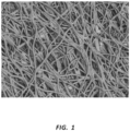
- Figure 1 is an SEM (950X) of an exemplary serially deposited fiber mat. The fibers of the mat of Figure 1 were deposited by rotational spinning of polytetrafluoroethylene (PTFE).
- Serially deposited fiber mats or lattices refer to structures composed at least partially of fibers successively deposited on a collector, on a substrate, on a base material, and/or on previously deposited fibers.
- the fibers may be randomly disposed, while in other embodiments the alignment or orientation of the fibers may be somewhat controlled or follow a general trend or pattern. Regardless of any pattern or degree of fiber alignment, because the fibers are deposited on the collector, substrate, base material, and/or previously deposited fibers, the fibers are not woven, but rather serially deposited.
- the terms “mat” and “lattice” are intended to be broadly construed as referring to any such structure, including tubes, spheres, sheets, and so on.
- the term “membrane” as used herein refers to any structure comprising serially deposited fibers having a thickness which is smaller than at least one other dimension of the membrane. Examples of membranes include, but are not limited to, serially deposited fiber mats or lattices forming sheets, strips, tubes, spheres, covers, layers, and so forth.
- Rotational spinning is one example of how a material may be serially deposited as fibers.
- a rotational spinning process comprises loading a polymer solution or dispersion into a cup or spinneret configured with orifices on the outside circumference of the spinneret. The spinneret is then rotated, causing (through a combination of centrifugal and hydrostatic forces, for example) the flowable material within the spinneret to be expelled from the orifices. The material may then form a "jet" or "stream” extending from the orifice, with drag forces tending to cause the stream of material to elongate into a small diameter fiber. The fibers may then be deposited on a collection apparatus, a substrate, or other fibers.
- the fibers may be dried, cooled, sintered, or otherwise processed to set the structure or otherwise harden the fiber mat.
- polymeric fibers rotational spun from a dispersion may be sintered to remove solvents, fiberizing agents, or other materials as well as to set the structure of the mat.
- an aqueous polytetrafluoroethylene (PTFE) dispersion may be mixed with polyethylene oxide (PEO) (as a fiberizing agent) and water (as a solvent for the PEO), and the mixture rotational spun. Sintering by heating the collected fibers may set the PTFE structure, evaporate off the water, and sublimate the PEO.
- PEO polyethylene oxide
- Exemplary methods and systems for rotational spinning can be found in U.S. Patent Application No. 13/742,025, filed on January 15, 2013 , and titled "Rotational Spun Material Covered Medical Appliances and Methods of Manufacture,".
- Rotational spinning processes and electrospinning processes may produce serially deposited fiber mats with differing characteristics. For example, as compared to electrospinning processes, rotational spinning may exhibit superior yeild, performance, and scaling. Rotational spinning processes may exhibit greater repeatability, reliability, and quality compared to electrospinning. In other words, rotational spun fiber mats may exhibit more consistency within closer tolerances as compared to electrospun fiber mats. Rotational spinning may be more directly scalable to large operations. Whereas electrospinning on a large scale may entail high voltage and other difficulties that further introduce time, cost, and variability, rotational spinning may more directly and simply scale, producing more consistent fiber mats.
- Electrospinning is another technique of how a material may be serially deposited as fibers.
- One example of an electrospinning process comprises loading a polymer solution or dispersion into a syringe coupled to a syringe pump. The material is forced out of the syringe by the pump in the presence of an electric field. The material forced from the syringe may elongate into fibers that are then deposited on a grounded collection apparatus, such as a collector or substrate. The system may be configured such that the material forced from the syringe is electrostatically charged, and thus attracted to the grounded collection apparatus. As with rotational spinning, once collected, the fibers may be dried, cooled, sintered, or otherwise processed to set the structure or otherwise harden the fiber mat.
- polymeric fibers electrospun from a dispersion may be sintered to remove solvents, fiberizing agents, or other materials as well as to set the structure of the mat.
- one technique of electrospinning comprises electrospinning an aqueous PTFE dispersion mixed with PEO and water (as a solvent for the PEO). Sintering by heating the collected fibers may set the PTFE structure, evaporate off the water, and sublimate the PEO.
- Exemplary methods and systems for electrospinning medical devices can be found in U.S. Patent Application Nos.
- Rotational spinning and/or electrospinning may be utilized to create a variety of materials or structures comprising serially deposited fibers.
- the microstructure or nanostructure of such materials, as well as the porosity, permeability, material composition, rigidity, fiber alignment, and so forth, may be controlled or configured to promote biocompatibility or influence interactions between the material and cells or other biologic material.
- a variety of materials may be serially deposited through processes such as rotational spinning and electrospinning: for example, polymers, ceramics, metals, materials which may be melt-processed, or any other material having a soft or liquid form.
- a variety of materials may be serially deposited through rotational spinning or electrospinning while the material is in a solution, dispersion, molten or semi-molten form, and so forth.
- the present disclosure may be applicable to any material discussed herein being serially deposited as fibers onto any substrate or in any geometry discussed herein.
- examples of particular materials or structures given herein may be analogously applied to other materials and/or structures.
- Rotational spinning, electrospinning, or other analogous processes may be used to create serially deposited fiber mats as disclosed herein.
- examples may be given of serially deposited fiber mats generally, or the examples may specify the process (such as rotational spinning or electrospinning) utilized to create the serially deposited fiber mat. It is within the scope of this disclosure to analogously apply any process for creating serially deposited fibers to any disclosure or example below, regardless of whether the disclosure specifically indicates a particular mat was formed according to a particular process.
- Expanded polytetrafluoroethylene is also used as a component of a layered medical appliance.
- ePTFE may be formed when a sheet of PTFE is heated and stretched.
- the sheet of ePTFE may be formed, for example, by extrusion or other methods. Heating and stretching of the PTFE sheet to form ePTFE changes the microstructure of the sheet, making it more porous and creating nodes of material with fibrils of material extending there between.
- United States Patent No. 3,664,915 of W.L. Gore describes various processes for heating and stretching PTFE to create ePTFE. In some processes, the ePTFE will be expanded to a greater extent along a longitudinal direction as compared to a transverse direction.
- ePTFE mats may be described as having an axis of expansion, or the direction in which the majority of the expansion was done. In some instances the ratio of expansion in the longitudinal direction to expansion in a transverse direction may be between 10:1 and 20:1.
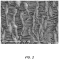
- Figure 2 is an exemplary SEM (950X) of an ePTFE membrane.
- ePTFE may also be further processed after it has been initially formed. Some such processes may densify the ePTFE, reducing the porosity and increasing the strength. In some instances such post-processing may be used to contract fibrils extending between the nodes of the ePTFE to create a layer that is substantially impermeable to tissue and/or fluid. Thus, ePTFE layers may be configured with various permeability characteristics, including layers which are impermeable to cellular or tissue migration across the layer. Further, such post-processing may increase the strength of the layer due to the resulting work processing stresses created in the material.
- Characteristics of mats may be determined in a variety of ways.
- internodal distance, or IND can be used to characterize the degree of expansion and/or the porosity of the ePTFE.
- the internodal distance refers to the average distance between adjacent nodes of the membrane.
- Percent porosity is another measurement that may be used to characterize membranes with porous sections. This method can be used, for example, to characterize ePTFE and/or serially deposited fibers. Percent porosity refers to the percent of open space to closed space (or space filled by fibers) in a membrane or mat. Thus, the more open the structure is, the higher the percent porosity measurement. In some instances, percent porosity may be determined by first obtaining an image, such as an SEM, of a material. The image may then be converted to a "binary image," or an image showing only black and white portions, for example. The binary image may then be analyzed and the percent porosity determined by comparing the relative numbers of each type of binary pixel.
- an image such as an SEM
- an image may be converted to a black and white image wherein black portions represent gaps or holes in the membrane while white portions represent the fibers or other structure of the membrane. Percent porosity may then be determined by dividing the number of black pixels by the number of total pixels in the image.
- a code or script may be configured to make these analyses and calculations.
- the "average pore size" of an ePTFE of serially deposited mat may be used as an alternate or additional measurement of the properties of the mat.
- the complex and random microstructure of serially deposited mats presents a challenge to the direct measurement of the average pore size of the mat.
- Average pore size can be indirectly determined by measuring the permeability of the mat to fluids using known testing techniques and instruments. Once the permeability is determined, that measurement may be used to determine an "effective" pore size of the serially deposited mat.
- the "pore size" of a serially deposited mat and/or an expanded membrane refers to the pore size of a known membrane which corresponds to the permeability of the serially deposited or expanded fabric when measured using ASTM standard F316 for the permeability measurement.
- ASTM standard F316 Standard Test Methods for Pore Size Characteristics of Membrane Filters by Bubble Point and Mean Flow Pore Test. In some instances this test can be used as a quality control after configuring a mat based on other measurements such as percent porosity.
- average pore diameter and average pore area of an ePTFE or serially deposited mat may be calculated programmatically using software to analyze an image, such as an SEM.
- an SEM may be evaluated using software analysis to measure various characteristics of a material layer.
- the SEM image may first be converted to a "binary image," or an image showing only black and white portions, as discussed above.
- the binary image may then be analyzed, the fibers or other features of the layer identified, and characteristics determined by comparing the relative numbers and placements of each type of binary pixel.
- an image may be converted to a black and white image wherein black portions represent gaps or holes in a serially deposited fiber mat while white portions represent the fibers of the mat.
- the software thus identifies the presence and position of fibers and pores or open portions of the fiber mat.
- Characteristics such as fiber width and pore size may be determined by analyzing these binary images. Still further, characteristics of relative fibers, such as the number of fiber branches, intersections, bundles, fiber density, and so forth, may be determined through similar analysis. In some instances, a code or script may be configured to make various analyses and calculations.
- United States Patent Application No. 14/207,344, titled “Serially Deposited Fiber Materials and Associated Devices and Methods,” filed on March 12, 2014 discusses various methods of characterizing and evaluating construct layers.
- an image may be evaluated to distinguish between areas comprising fibers and open areas, such as by creating a binary image as discussed above. Pores, or areas within a fiber mat encapsulated by intersecting or branched fibers, may then be identified.
- a large sample of pores may be randomly selected from the target image. In some instances, between 50 and 300 pores may comprise the sample. The diameter of a particular pore may be calculated by tracing multiple diameters of equal angular spacing around the pore through the centroid of the pore. In an example, 30 such diameters were used to determine a calculated pore size. The measured diameters are then averaged to determine the calculated effective diameter of the pore.
- each identified pore may also be computed based on the pixel area of each pore.
- Each pore identified for sampling may be manually checked to confirm proper identification of pores.
- the average pore diameter of a fiber mat may then be computed by averaging the calculated effective diameters of the identified pore.
- material total porosity may also be determined by the percentage of dark pixels to light pixels in the image.
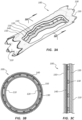
- Figures 3A-3C are schematic depictions of an exemplary medical appliance 100. Specifically, Figure 3A is a perspective cut-away view of the medical appliance 100. Figure 3B is a cross-sectional view of the medical appliance 100 taken through line 3B-3B of Figure 3A. Figure 3C is another cross-sectional view showing the layers of the medical appliance 100.
- the medical appliance 100 of Figures 3A-3C may be configured as a vascular stent-graft.
- the medical appliance 100 is shown with four distinct layers disposed about a scaffolding structure 130.
- the medical appliance comprises a first layer 110 of rotationally spun PTFE.
- the rotationally spun PTFE first layer 110 defines the luminal surface of the medical appliance 100.
- This luminal first layer 110 may be designed to interact with blood flow within the vasculature.
- the microporous structure of the rotationally spun first layer 110 may be configured to accommodate or allow endothelial cell growth on the luminal surface of the medical appliance 100 when disposed within the vasculature of a patient.
- a serially deposited material is disposed on the luminal surface of the medical appliance 100.
- rotational spun PTFE, electrospun PTFE, or other polymers may be used on this layer.
- Serially deposited layers within the scope of this disclosure may comprise a wide variety of characteristics. For example, serially deposited layers with a percent porosity between 35% and 75%, including between 40% and 60%, and between 45% and 55%, are within the scope of this disclosure. Similarly, serially deposited layers with an average fiber diameter between 0.25 micron and 2.5 micron, including between 0.5 micron and 1.75 micron, and between 0.75 micron and 1.25 micron, are within the scope of this disclosure. Average pore diameter for serially deposited layers within the scope of this disclosure may range from one micron to five micron, including from two micron to four micron and from two micron to three micron.
- the average pore area of serially deposited layers within the scope of this disclosure may range from three square micron to 15 square micron, including from four square micron to 10 square micron, and from four square micron to eight square micron. Any serially deposited layer forming a portion of a construct described herein may be configured with any of these properties.
- the medical appliance 100 comprises a second layer 120 disposed radially around the first layer 110.
- the second layer 120 may be configured to reinforce or otherwise strengthen the first layer 110 of rotational spun material.
- this second layer 120 comprises ePTFE.
- the ePTFE layer reinforces the rotational spun first layer 110.
- the ePTFE layer may increase the tensile strength, burst strength, hoop strength, or other properties of the medical appliance 100 as compared to a device utilizing only serially deposited fibers.
- the ePTFE may comprise densified ePTFE and/or ePTFE with a small IND.
- the ePTFE second layer 120 may be configured with low porosity and high work history to create a high-strength layer.
- ePTFE layers within the scope of this disclosure may be configured with a variety of properties.
- ePTFE layers with an average internodal distance (IND) of less than 80 micron, including less than 70 micron, less than 60 micron, less than 50 micron, less than 40 micron, less than 30 micron, less than 20 micron, and less than 10 micron are within the scope of this disclosure.
- exemplary ePTFE layers within the scope of this disclosure may have an average IND of less than 10, nine, eight, seven, six, five, four, three, two, or one micron.
- ePTFE layers within the scope of this disclosure may have percent porosities between 40% and 80%, including percent porosities greater than 50%. Further, such layers may have an average pore diameter greater than 1 micron, including between one micron and three micron. Average pore area may be greater than two square micron, including between two square micron and 15 square micron. Finally, the average fibril diameter of the ePTFE layer may be greater than 0.2 micron, including between 0.2 micron and 0.6 micron.
- One exemplary ePTFE layer may have an IND of 10 micron, a percent porosity of 75%, average pore diameter of 4.38 micron, average pore area of 14.7 square micron, and average fibril thickness of 0.33 micron.
- a second exemplary ePTFE layer may have an IND of 10 micron, a percent porosity of 65%, average pore diameter of 3.5 micron, average pore area of 10.6 square micron, and average fibril thickness of 0.35 micron.
- a third exemplary ePTFE layer may have an IND of 10 micron, a percent porosity of 50%, average pore diameter of 2.78 micron, average pore area of 7.5 square micron, and average fibril thickness of 0.5 micron.
- ePTFE layers according to the three exemplary layers above, as well as ePTFE layers within any of the ranges disclosed herein, may be used in multilayered constructs within the scope of this disclosure.
- ePTFE layers may have a greater tensile strength, creep resistance, or other mechanical properties.
- Multilayered prostheses according to the invention are comprised of both serially deposited layers and ePTFE layers wherein at least one ePTFE layer has at least five times greater tensile strength than at least one serially deposited layer within the same construct.
- Multilayered coverings or constructs wherein one or more layers of ePTFE provide at least 90% of at least one mechanical property (such as tensile strength, hoop strength, burst strength, and/or creep resistance) of the covering or construct are within the scope of this disclosure.
- a construct may have no scaffolding structure.
- the comparison of properties may only refer to the properties provided by the covering portion, meaning the layers of material disposed about a scaffolding structure, but not including the scaffolding structure.
- this comparison of properties may refer to the properties of the entire construct, including a scaffolding structure.
- coverings or constructs wherein at least 85%, 80%, 75%, 70%, and 65% of at least one mechanical property is provided by one or more layers of ePTFE are within the scope of this disclosure.
- the scaffolding structure 130 is disposed around the second layer 120 of the medical appliance 100.
- This scaffolding structure 130 may comprise a metal stent-for example, a stent composed of nitinol, stainless steel, or alloys thereof. Additionally, other materials, such as polymer scaffolds, are within the scope of this disclosure.
- the scaffolding structure 130 may be understood as a third layer of the medical applicance 100.
- the scaffolding structure 130 may be disposed between other such layers (such as the second layer 120 and the fourth layer 140) is can be understood as representing a layer of the medical device 100.
- the scaffolding structure may comprise a relative tight lattice, including a polymer lattice, which may tend to form a layer of a medical appliance 100.
- References herein to a multilayered construct or multilayered component may be understood as referring to the entire medical appliance 100, including the scaffolding structure, or may apply only to layers of material (such as 110, 120, 140, and 150) disposed about a scaffolding stucture 130 considered separately from the scaffolding structure 130.
- the medical appliance 100 may further comprise an impermeable layer.
- the fourth layer 140 may comprise a polymer layer that is impermeable to cellular growth, fluid passage, or both.
- An impermeable layer may be configured to prevent fluid leakage across the medical appliance and/or prevent cellular growth across the appliance. Containment of cellular growth across the appliance may lengthen the useful life of the appliance, as bodily tissues are prevented from growing through the medical appliance and occluding the lumen thereof.
- the impermeable fourth layer 140 may comprise fluorinated ethylene propylene (FEP) that may be sprayed, dipped, or laminated onto the construct.
- FEP layers within the scope of this disclosure may thus be applied as a film or membrane which is rolled onto or otherwise applied to a construct, as well as applied as a liquide or solution applied by spraying or dipping.
- the medical appliance 100 may further comprise a fifth layer 150 disposed around the impermeable fourth layer 140.
- This fifth layer 150 may define an abluminal surface of the medical appliance 100.
- this fifth layer 150 may comprise ePTFE and may be densified and/or have a relatively small IND or pore size.
- This layer may be configured to provide strength to the construct and may or may not comprise ePTFE having the same properties as the second layer 120 of the illustrated construct.
- the fourth layer 140 and the fifth layer 150 may be constructed as a composite layer.
- a fifth layer 150 comprising ePTFE may be sprayed or dipped with FEP such that the FEP coats the ePTFE and fills in the pores and openings in the ePTFE.
- a composite layer of ePTFE and FEP may thus be configured with the properties and functions of both the fourth layer 140 and fifth layer 150.
- any of the layers discussed above may be comprised of one or more sublayers.
- the first layer 110 is comprised of serially deposited fibers, and the first layer 110 in turn, comprises multiple sublayers of serially deposited fibers or fiber mats.
- the first layer 110 may thus consist of a first sublayer comprising serially deposited fibers and a second sublayer also comprising serially deposited fibers.
- the sublayers may be deposited at different times during manufacture and/or may be sintered separately, for example.
- the first layer 110 may also include other materials, disposed between the sublayers, for example to aid in coupling the sublayers to each other. Any number of sublayers may be combined within a single layer.
- the wall thickness of a multilayered covering for a medical device may be between 50 micron and 500 micron, including between 50 micron and 450 micron, between 50 micron and 400 micron, between 50 micron and 350 micron, between 50 micron and 300 micron, between 50 micron and 250 micron, between 50 micron and 200 micron, between 50 micron and 150 micron, and between 75 micron and 125 micron.
- the wall thickness of any individual layer within a multilayered construct may be between five micron and 100 micron, including between five micron and 75 micron, between five micron and 60 micron, between 25 micron and 75 micron, between 10 micron and 30 micron, and between five micron and 15 micron. Any layer described herein may fall within any of these ranges, and the thicknesses of each layer of a multilayered construct may be configured such that the total wall thickness of the covering falls within the ranges described above.
- Multilayered constructs that have more or fewer layers than the exemplary medical appliance 100 are likewise within the scope of this disclosure. For example, constructs having two, three, four, five, six, seven, or more layers are all within the scope of this disclosure.
- a single layer may be used to provide the characteristics associated with two or more layers in the exemplary medical appliance 100.
- ePTFE with a sufficiently small IND may be substantially impermeable to tissue ingrowth and/or fluid passage. Therefore, in some embodiments, a single layer of low-porosity ePTFE may provide the characteristics associated with the second 120, fourth 140, and fifth 150 layers of the exemplary medical appliance 100.
- a medical appliance comprising a single luminal layer of serially deposited fibers and a single layer of ePTFE is within the scope of this disclosure.
- any of the layers described in connection with the exemplary medical appliance 100 may be disposed in any relative order, with the exception that a layer configured as a blood-contacting layer of the device (if present) will be disposed on the luminal surface of the construct.
- medical appliances within the scope of this disclosure may be manufactured in a variety of ways. Each layer may be individually formed then disposed on the construct, or one or more layers may be formed on the construct in the first instance.
- a method of manufacture may comprise serially depositing PTFE fibers on a mandrel or other collection surface and sintering the fibers. This layer of serially deposited fibers may form the first layer 110 of the medical appliance 100.
- a second layer 120 may then be applied to the medical appliance 100.
- This second layer 120 may comprise ePTFE and may be densified.
- the ePTFE may be obtained as a sheet which is applied around the first layer 110.
- the second layer 120 may be applied around the first layer 110 before the first layer 110 is sintered. Sintering of the first layer 110 while the second layer 120 is disposed therearound may facilitate bonding between the first 110 and second 120 layers.
- the second layer 120 may be applied as unsintered ePTFE around the first layer 110, which in turn may comprise unsintered serially deposited PTFE fibers. Accordingly, the first 110 and second 120 layers may be simultaneously sintered, which may facilitate bonding between the layers. Any layer of PTFE, including serially deposited layers and layers of ePTFE, may be applied as an unsintered layer.
- the mechanical properties of an ePTFE layer may be derived from the relative disposition of ePTFE sublayers which comprise the overall ePTFE layer.
- Each sublayer may impart different properties to the overall construct.
- the sublayers may be stronger in the direction the ePTFE was expanded than in a transverse direction.
- Application of such sublayers such that the axis of expansion of each sublayer is perpendicular to the axis of expansion of adjacent layers may create a layer of ePTFE with more uniform longitudinal and radial properties.
- Prostheses within the scope of this disclosure comprise ePTFE sublayers disposed such that the axis of expansion of a first layer is disposed at any angle to the axis of expansion of an adjacent layer.
- constructs wherein the axis of expansion of an ePTFE sublayer is aligned with the central axis of a prosthesis, for example the longitudinal axis of a tubular prosthesis, are within the scope of this disclosure.
- this may be done by obtaining a strip of ePTFE that is narrower than the length of the medical appliance 100.
- the strip may be helically wrapped around the first layer 110 of the medical appliance 100. In some instances the strip may be wrapped at about 45° to the longitudinal axis of the medical appliance 100.
- the strip may comprise a sublayer of the second layer 120.
- a second sublayer may be applied, also at about 45° to the longitudinal axis of the medical appliance 100, but applied such that the axis of expansion of the second sublayer is perpendicular to the first strip applied.
- the combined strength of the sublayers may thus be arranged such that the sum of the strength of the sublayers is similar in the longitudinal and radial directions of the medical appliance 100. Any other angle of relative positioning of sublayers is within the scope of this disclosure, and the relative angles may be configured to create a construct with certain properties and strengths in various directions.
- a metal or polymer scaffolding structure 130 may then be applied around the second layer 120 of the medical appliance 100.
- the fourth layer 140 may then be applied.
- the fourth layer 140 may comprise FEP and may be applied as a film, dipped, sprayed, or otherwise applied.
- the fifth layer 150 may be applied around the fourth layer 140.
- the fifth layer 150 may or may not be applied in the same manner as the second layer 120 and may or may not have substantially the same properties as the second layer 120.
- the fifth layer 150 may or may not be sintered at the same time as other layers, for example, the second layer 120.
- the first 110 and second 120 layers may first be applied and sintered (either separately or simultaneously), the scaffolding structure 130 may then be applied, followed by the fourth layer 140.
- the fourth layer 140 may comprise FEP and may be applied as a film or as a liquid or solution.
- the fifth layer 150 may be sintered after it is applied around the fourth layer 140.
- a film FEP fourth layer 140 may bond to adjacent layers during the heating of the construct to sinter the fifth layer 150. Again the first 110 and second 120 layers may be previously sintered.
- Methods of deploying a medical appliance, such as medical appliance 100, within the body are also useful for understanding the invention.
- methods of promoting endothelial growth while resisting transmural tissue growth across the medical appliance are useful for understanding the invention.
- deployment of a medical appliance having a blood-contacting layer configured to promote endothelial growth and at least one other layer configured to resist tissue growth through the layer would be related to such a method.
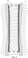
- Figure 4 is a cross-sectional schematic view of the medical appliance 100 deployed within a body lumen 50.
- the fifth layer (150 of Figure 3A ) which may comprise an abluminal surface of the medical appliance 100, may be disposed in direct contact with the wall of the body lumen 50.
- the first layer (110 of Figure 3A ) which may comprise a luminal surface of the medical appliance 100, may be disposed in direct communication with fluid flowing through the body lumen 50.
- Characteristics of the various other layers of the medical appliance 100 may also affect the interaction between the body lumen 50 and the medical appliance 100, though these layers may not be in direct contact with a surface of the body lumen 50.
- a cellular or fluid impermeable layer may prevent tissue or fluid from crossing the wall of the medical appliance 100, though such a layer may or may not be disposed in direct contact with the body lumen 50.
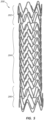
- FIG. 5 is a perspective view of a scaffolding structure 200 for a stent-graft.
- Such scaffolding structures may be coupled to coverings, including layered coverings, and may be configured to provide support and structure to the stent-graft.
- a scaffolding structure such as scaffolding structure 200, may be configured to resist radial compression of a stent-graft.
- references below may be directed to the scaffolding structure 200, it will be understood, by one having skill in the art and having the benefit of this disclosure, that disclosure relevant to the scaffolding structure 200 may analogously apply to a stent-graft or covered stent composed of the scaffolding structure 200.
- the scaffolding structure 200 may be configured with different resistance to radial force along the longitudinal length of the scaffolding structure 200.
- the scaffolding structure 200 comprises a proximal portion 202, a mid-body portion 204, and a distal portion 206.
- the scaffolding structure 200 may be configured such that it provides greater resistance to radial compression in one or more of these portions 202, 204, 206 as compared to at least one other portion 202, 204, 206 of the scaffolding structure 200.
- Differing resistance to radial force along the length of the scaffolding structure 200 may be designed to provide strength in certain areas (such as an area to be treated, such as an aneurysm) while providing softer portions of the scaffolding which may allow the scaffolding structure 200 to interact with healthy portions of the body in a more atraumatic way.
- one or more portions of a scaffolding structure may be configured to hold open diseased tissue within the body lumen 50.
- the radial resistance of the scaffolding structure 200, and any stent-graft comprising the scaffolding structure 200, may be a result of the material used to create the scaffolding structure 200; variations in the structure of the scaffolding structure 200, such as the degree to which the scaffolding structure 200 comprises a more open or more closed design; and other design parameters.
- the radial force along portions of the same scaffolding structure, stent, or stent-graft may vary by between 10% and 30%, between 30% and 60%, between 60% and 100%, more than 100%, and more than 200%.
- the scaffolding structure 200 may be configured such that the resistance to radial compression of the scaffolding structure 200 is greater in the mid-body portion 204 of the scaffolding structure 200 as compared to the proximal 202 and/or distal 206 portions thereof.
- the mid-body portion 204 may have less resistance to radial compression or, in other words, may be softer than the proximal 202 and/or distal 206 portions thereof.
- the proximal 202 and/or distal 206 portions of a scaffolding structure 200 may be configured to reduce tissue aggravation at the edge of the scaffolding structure 200.
- the resistance to radial compression of one or more ends of the scaffolding structure 200 may be configured to reduce the occurrence of edge stenosis. Moreover, the resistance to radial compression of one or more ends of the scaffolding structure 200 may be configured to promote endothelial cell growth on a surface of a stent-graft coupled to the scaffolding structure 200. The resistance to radial compression along one or more portions of the scaffolding structure 200 may be configured to match the compliance of a body vessel in which the scaffolding structure 200 is designed for deployment.
- Scaffolding structures 200 may comprise metals, including stainless steel, nitinol, various super elastic or shape memory alloys, and so forth. Scaffolding structures 200 may also comprise polymers. Further, scaffolding structures 200 may comprise one or more biologic agents, including embodiments wherein a metal or polymeric scaffolding structure is integrated with a drug or other biologic agent.
- Scaffolding structures 200 may be formed in a variety of ways.
- the scaffolding structure 200 may be formed of a wire.
- the scaffolding structure 200 may be formed from a tube of material, including embodiments wherein the scaffolding structure 200 is cut from a tube of material.
- Scaffolding structures 200 may be formed using laser cutting, etching processes, and powdered metallurgy and sintering processes; formed from molds; and formed using rapid manufacturing techniques.
- a stent or stent-graft with or without a scaffolding structure such as scaffolding structure 200, may be configured to exert an outward radial force when disposed within a body lumen. This force may be configured to keep the lumen open, prevent restenosis, inhibit migration of the stent or stent-graft, and so forth.
- a stent or stent-graft which subject body lumens to high radial forces may provoke an unwanted biologic response and/or result in unnecessary trauma to the body lumen.
- a stent or stent-graft may be configured to exert radial force within a range that is acceptable for healing and trauma, while still achieving treatment goals.
- Some stents or stent-grafts may be configured such that the stent or stent-graft resists localized compression, for example due to a point or pinch force, even when the localized force exceeds the circumferential outward radial force of the stent or stent-graft.
- the stent may be configured to resist relatively high point forces (for example, as may be exerted by a ligament or other biologic structure) on the stent or stent-graft without exerting high radial forces on the entire body lumen.
- Stents or stent-grafts within the scope of this disclosure may be configured such that the point force required to fully collapse the stent is between five N and 15 N, including between 7.5 N and 12.5 N.
- Stents or stent-grafts within the point force ranges disclosed above may have a lower circumferential radial outward force.
- stents or stent-grafts within the scope of this disclosure may have a radial outward force at 20% oversizing of between 0.3 N/mm and 1.3 N/mm, including between 0.4 N/mm and 1 N/mm.
- the point force required to fully collapse the stent may be significantly greater than the radial outward force exerted by the stent on a body lumen.
- Multilayered stent covers within the scope of this disclosure may be tested by pressurizing water within the lumen of a stent according to the present disclosure. By increasing the water pressure, the burst strength and water permeability of the stent can be determined.
- Water entry pressure is herein defined as the internal water pressure at which a second bead of water forms on the outside of the tubular structure being tested. The device does not burst or fail in the water entry pressure test.
- Medical devices within the scope of this disclosure may have water entry pressures between zero psi and 10 psi (1 psi is 6894,755 N/m2) including between four psi and eight psi.
- medical devices within the scope of this disclosure may have water entry pressures greater than five psi, greater than 10 psi, greater than 20 psi, greater than 30 psi, greater than 40 psi, or greater than 50 psi.
- the ePTFE layer provides at least 80% of the tensile strength, measured in at least one direction, of a construct consisting of the serially deposited fiber layer and the PTFE layer. In these embodiments, the ePTFE layer may provide at least 90% of the tensile strength of a construct consisting of the serially deposited fiber layer and the ePTFE layer. In these embodiments, the ePTFE layer may be disposed on an abluminal surface of the prosthesis. In these embodiments an axis of longitudinal expansion of at least one of the ePTFE sublayers may be perpendicular to an axis of longitudinal expansion of at least one adjacent ePTFE sublayer.
- an axis of longitudinal expansion of at least one of the ePTFE sublayers may be aligned with a central axis of the vascular prosthesis.
- each ePTFE sublayer may have an average pore size of 6 microns or less.
- the ePTFE layer may be impermeable to red blood cell migration across the layer.
- These embodiments may comprise a tissue and cell impermeable layer of fluorinated ethylene propylene (FEP).
- FEP fluid impermeable layer of fluorinated ethylene propylene (FEP).
- the FEP layer is at least partially disposed within pores of the ePTFE layer.
- These embodiments may comprise a stent scaffold disposed between the serially deposited fiber layer and the PTFE layer.
- the prosthesis may exert a radial outward force of less than 2 N/mm at 20% oversizing or the point force required to fully collapse the multilayered vascular prosthesis is greater than 5 N.
- the serially deposited fiber layer may comprise rotational spun fibers.
- the ePTFE layer has an average pore size of less than 6 microns.
- the ePTFE layer may be disposed on an abluminal surface of the prosthesis.
- These embodiments may comprise sublayers of fluorinated ethylene propylene (FEP) disposed between one or sublayers of the ePTFE layer.
- FEP fluorinated ethylene propylene
- an axis of longitudinal expansion of at least one of the ePTFE sublayers may be perpendicular to an axis of longitudinal expansion of at least one adjacent ePTFE sublayer.
- an axis of longitudinal expansion of at least one of the ePTFE sublayers may be aligned with a central axis of the vascular prosthesis.
- the ePTFE layer is impermeable to red blood cell migration across the layer.
- These embodiments may comprise a fluid impermeable layer of fluorinated ethylene propylene (FEP) disposed between the serially deposited fiber layer and the ePTFE layer.
- FEP fluorinated ethylene propylene
- These embodiments may comprise a tissue and cell impermeable layer of fluorinated ethylene propylene (FEP).
- FEP fluorinated ethylene propylene
- These embodiments may comprise a stent scaffold disposed between the serially deposited fiber layer and the ePTFE layer.
- the prosthesis may exert a radial outward force of less than 2 N/mm at 20% oversizing or the point force required to fully collapse the multilayered vascular prosthesis is greater than 5 N.
- the serially deposited fiber layer may comprise rotational spun fibers.
- the ePTFE layer is disposed on an abluminal surface of the prosthesis.
- an axis of longitudinal expansion of at least one of the ePTFE sublayers may be perpendicular to an axis of longitudinal expansion of at least one adjacent ePTFE sublayer.
- an axis of longitudinal expansion of at least one of the ePTFE sublayers may be aligned with a central axis of the vascular prosthesis.
- These embodiments may comprise a tissue and cell impermeable layer of fluorinated ethylene propylene (FEP).
- the ePTFE layer may be impermeable to red blood cell migration across the layer.
- These embodiments may comprise a fluid impermeable layer of fluorinated ethylene propylene (FEP) disposed between the serially deposited fiber layer and the ePTFE layer.
- These embodiments may comprise a stent scaffold disposed between the serially deposited fiber layer and the ePTFE layer.
- the prosthesis may exert a radial outward force of less than 2 N/mm at 20% oversizing or the point force required to fully collapse the multilayered vascular prosthesis is greater than 5 N.
- the serially deposited fiber layer may comprise rotational spun fibers.
- a method of constructing a multilayered vascular prosthesis comprising: coupling an expanded polytetrafluoroethylene (ePTFE) layer with an internodal distance (IND) of 6 micron or less to a serially deposited layer, such that the serially deposited layer may be disposed on a lumenal surface of the multilayered vascular prosthesis.
- the method may comprise applying fluorinated ethylene propylene (FEP) to the ePTFE layer such that at least a portion of the FEP may be disposed within pores of the ePTFE layer.
- FEP fluorinated ethylene propylene
- the method may comprise FEP sprayed or wrapped onto the ePTFE layer.
- the method may comprise simultaneously sintering the ePTFE layer and the serially deposited layer while the layers may be in contact with each other.
- the method may comprise rotational spinning of the serially deposited layer.
- the FEP and ePTFE layer may comprise a tissue and cell impermeable boundary.
- the ePTFE layer may be constructed by coupling a first sublayer of ePTFE to a second sublayer of ePTFE, wherein the axis of expansion of the second sublayer may be disposed at an angle to the axis of expansion of the first sublayer.
- An axis of longitudinal expansion of at least one of the ePTFE sublayers may be perpendicular to an axis of longitudinal expansion of at least one adjacent ePTFE sublayer.
- An axis of longitudinal expansion of at least one of the ePTFE sublayers may be aligned with a central axis of the vascular prosthesis.
- the serially deposited layer may comprise polytetrafluoroethylene (PTFE) fibers. At least one of the ePTFE layer and the serially deposited layer may be unsintered when initially disposed on the multilayered vascular prosthesis.
Landscapes
- Health & Medical Sciences (AREA)
- Animal Behavior & Ethology (AREA)
- Veterinary Medicine (AREA)
- Public Health (AREA)
- General Health & Medical Sciences (AREA)
- Life Sciences & Earth Sciences (AREA)
- Chemical & Material Sciences (AREA)
- Vascular Medicine (AREA)
- Oral & Maxillofacial Surgery (AREA)
- Transplantation (AREA)
- Heart & Thoracic Surgery (AREA)
- Epidemiology (AREA)
- Engineering & Computer Science (AREA)
- Biomedical Technology (AREA)
- Chemical Kinetics & Catalysis (AREA)
- Medicinal Chemistry (AREA)
- Cardiology (AREA)
- Dermatology (AREA)
- Surgery (AREA)
- Gastroenterology & Hepatology (AREA)
- Pulmonology (AREA)
- Physics & Mathematics (AREA)
- Optics & Photonics (AREA)
- Polymers & Plastics (AREA)
- Organic Chemistry (AREA)
- Dispersion Chemistry (AREA)
- Prostheses (AREA)
- Materials For Medical Uses (AREA)
- Laminated Bodies (AREA)
Claims (12)
- Mehrschichtige Gefäßprothese (100), die Folgendes umfasst:eine nacheinander aufgebrachte Faserschicht, die auf einer luminalen Oberfläche der Prothese angeordnet ist; undeine expandierte Polytetrafluorethylen ("ePTFE")-Schicht (120), die mit der nacheinander aufgebrachten Faserschicht (110) verbunden ist, wobei das ePTFE eine oder mehrere Unterschichten von ePTFE umfasst;wobei eine Achse der Längsausdehnung von mindestens einer der ePTFE-Unterschichten in einem Winkel zu einer Achse der Längsausdehnung von mindestens einer angrenzenden ePTFE-Unterschicht angeordnet ist; unddadurch gekennzeichnet, dass die ePTFE-Schicht mindestens eine fünffach größere Zugfestigkeit aufweist als die nacheinander aufgebrachte Schicht, was mindestens in einer Richtung gemessen wird.
- Mehrschichtige Gefäßprothese (100) nach Anspruch 1, wobei die ePTFE-Schicht (120) auf einer abluminalen Oberfläche (150) der Prothese angeordnet ist.
- Mehrschichtige Gefäßprothese (100) nach einem der Ansprüche 1-2, wobei eine Achse der Längsausdehnung von mindestens einer der ePTFE-Unterschichten senkrecht zu einer Achse der Längsausdehnung von mindestens einer angrenzenden ePTFE-Unterschicht vorliegt.
- Mehrschichtige Gefäßprothese (100) nach einem der Ansprüche 1-3, wobei eine Achse der Längsausdehnung von mindestens einer der ePTFE-Unterschichten mit einer Mittelachse der Gefäßprothese ausgerichtet ist.
- Mehrschichtige Gefäßprothese (100) nach einem der Ansprüche 1-4, die weiter eine gewebe- und zellundurchlässige Schicht (140) aus fluoriertem Ethylenpropylen (FEP) umfasst.
- Mehrschichtige Gefäßprothese (100) nach einem der Ansprüche 1-5, wobei die ePTFE-Schicht (120) für die Migration von roten Blutzellen durch die Schicht undurchlässig ist.
- Mehrschichtige Gefäßprothese (100) nach einem der Ansprüche 1-6, die weiter eine flüssigkeitsundurchlässige Schicht aus fluoriertem Ethylenpropylen (FEP) umfasst, die zwischen der nacheinander aufgebrachten Faserschicht (110) und der ePTFE-Schicht (120) angeordnet ist.
- Mehrschichtige Gefäßprothese (100) nach einem der Ansprüche 1-7, die weiter ein Stentgerüst (130) umfasst, das zwischen der nacheinander aufgebrachten Faserschicht und der ePTFE-Schicht angeordnet ist.
- Mehrschichtige Gefäßprothese (100) nach einem der Ansprüche 1-8, wobei die Prothese zur Ausübung einer nach außen gerichteten Radialkraft von weniger als 2 N/mm bei einer Überdimensionierung von 20 % konfiguriert ist oder die Punktkraft, die zum vollständigen Zusammenklappen der mehrschichtigen Gefäßprothese notwendig ist, größer als 5 N ist.
- Mehrschichtige Gefäßprothese (100) nach einem der Ansprüche 1-9, wobei die nacheinander aufgebrachte Faserschicht (110) rotationsgesponnene Fasern umfasst.
- Mehrschichtige Gefäßprothese (100) nach einem der Ansprüche 1-9, wobei die nacheinander aufgebrachte Faserschicht (110) elektrogesponnene Fasern umfasst.
- Mehrschichtige Gefäßprothese (100) nach einem der Ansprüche 1-11, wobei die ePTFE-Unterschichten durch Sintern verbunden sind.
Priority Applications (1)
| Application Number | Priority Date | Filing Date | Title |
|---|---|---|---|
| EP24173827.7A EP4417225A3 (de) | 2015-02-26 | 2016-02-25 | Geschichtete medizinische vorrichtungen und verfahren |
Applications Claiming Priority (3)
| Application Number | Priority Date | Filing Date | Title |
|---|---|---|---|
| US201562121187P | 2015-02-26 | 2015-02-26 | |
| PCT/US2016/019487 WO2016138221A1 (en) | 2015-02-26 | 2016-02-25 | Layered medical appliances and methods |
| EP16756335.2A EP3261589B1 (de) | 2015-02-26 | 2016-02-25 | Geschichtete medizinische anwendungen |
Related Parent Applications (2)
| Application Number | Title | Priority Date | Filing Date |
|---|---|---|---|
| EP16756335.2A Division EP3261589B1 (de) | 2015-02-26 | 2016-02-25 | Geschichtete medizinische anwendungen |
| EP16756335.2A Division-Into EP3261589B1 (de) | 2015-02-26 | 2016-02-25 | Geschichtete medizinische anwendungen |
Related Child Applications (2)
| Application Number | Title | Priority Date | Filing Date |
|---|---|---|---|
| EP24173827.7A Division-Into EP4417225A3 (de) | 2015-02-26 | 2016-02-25 | Geschichtete medizinische vorrichtungen und verfahren |
| EP24173827.7A Division EP4417225A3 (de) | 2015-02-26 | 2016-02-25 | Geschichtete medizinische vorrichtungen und verfahren |
Publications (2)
| Publication Number | Publication Date |
|---|---|
| EP3785677A1 EP3785677A1 (de) | 2021-03-03 |
| EP3785677B1 true EP3785677B1 (de) | 2024-08-07 |
Family
ID=56789806
Family Applications (3)
| Application Number | Title | Priority Date | Filing Date |
|---|---|---|---|
| EP20190128.7A Active EP3785677B1 (de) | 2015-02-26 | 2016-02-25 | Geschichtete medizinische geräte |
| EP24173827.7A Pending EP4417225A3 (de) | 2015-02-26 | 2016-02-25 | Geschichtete medizinische vorrichtungen und verfahren |
| EP16756335.2A Active EP3261589B1 (de) | 2015-02-26 | 2016-02-25 | Geschichtete medizinische anwendungen |
Family Applications After (2)
| Application Number | Title | Priority Date | Filing Date |
|---|---|---|---|
| EP24173827.7A Pending EP4417225A3 (de) | 2015-02-26 | 2016-02-25 | Geschichtete medizinische vorrichtungen und verfahren |
| EP16756335.2A Active EP3261589B1 (de) | 2015-02-26 | 2016-02-25 | Geschichtete medizinische anwendungen |
Country Status (8)
| Country | Link |
|---|---|
| US (5) | US10028852B2 (de) |
| EP (3) | EP3785677B1 (de) |
| JP (1) | JP6777642B2 (de) |
| KR (1) | KR102649651B1 (de) |
| CA (2) | CA2975391C (de) |
| DK (1) | DK3261589T3 (de) |
| ES (1) | ES2989899T3 (de) |
| WO (1) | WO2016138221A1 (de) |
Families Citing this family (36)
| Publication number | Priority date | Publication date | Assignee | Title |
|---|---|---|---|---|
| EP2667829B1 (de) * | 2011-01-28 | 2021-09-22 | Merit Medical Systems, Inc. | Elektrogesponnener ptfe-beschichteter stent und verwendungsverfahren dafür |
| WO2013025819A2 (en) * | 2011-08-16 | 2013-02-21 | The University Of Kansas | Fibrous tracheal patch |
| CN110064076A (zh) | 2012-01-16 | 2019-07-30 | 麦瑞通医疗设备有限公司 | 被旋转纺丝材料覆盖的医疗器械和制造方法 |
| US8968387B2 (en) * | 2012-07-23 | 2015-03-03 | Abbott Cardiovascular Systems Inc. | Shape memory bioresorbable polymer peripheral scaffolds |
| US10507268B2 (en) * | 2012-09-19 | 2019-12-17 | Merit Medical Systems, Inc. | Electrospun material covered medical appliances and methods of manufacture |
| HK1217663A1 (zh) * | 2013-01-09 | 2017-01-20 | Harvard Apparatus Regenerative Technology, Inc. | 合成支架 |
| WO2014159710A1 (en) | 2013-03-13 | 2014-10-02 | Merit Medical Systems, Inc. | Serially deposited fiber materials and associated devices and methods |
| WO2014159399A1 (en) | 2013-03-13 | 2014-10-02 | Merit Medical Systems, Inc. | Methods, systems, and apparatuses for manufacturing rotational spun appliances |
| EP3785677B1 (de) | 2015-02-26 | 2024-08-07 | Merit Medical Systems, Inc. | Geschichtete medizinische geräte |
| WO2017004136A1 (en) | 2015-06-30 | 2017-01-05 | Tela Bio, Inc. | Corner-lock stitch patterns |
| WO2017015421A1 (en) | 2015-07-21 | 2017-01-26 | Tela Bio, Inc. | Compliance control stitching in substrate materials |
| WO2017151900A1 (en) | 2016-03-02 | 2017-09-08 | Peca Labs, Inc. | Expandable implantable conduit |
| US10456237B2 (en) * | 2016-03-07 | 2019-10-29 | Boston Scientific Scimed, Inc. | Esophageal stent including a valve member |
| WO2017189772A1 (en) | 2016-04-26 | 2017-11-02 | Tela Bio, Inc. | Hernia repair grafts having anti-adhesion barriers |
| US20220401711A9 (en) * | 2016-06-20 | 2022-12-22 | Csf-Dynamics A/S | Shunt device and a method for shunting cerebrospinal fluid |
| US10610357B2 (en) * | 2016-10-10 | 2020-04-07 | Peca Labs, Inc. | Transcatheter stent and valve assembly |
| CN109803590B (zh) * | 2016-10-10 | 2021-10-29 | 魏峥 | 具支架的血液导管 |
| US20190117369A1 (en) * | 2017-10-25 | 2019-04-25 | Cook Medical Technologies Llc | Layered cover material and method of use thereof |
| EP3761963B1 (de) | 2018-03-09 | 2025-01-22 | Tela Bio, Inc. | Chirurgisches reparaturtransplantat |
| CN108560136A (zh) * | 2018-06-11 | 2018-09-21 | 江苏百优达生命科技有限公司 | 一种复合型医用毡片 |
| IL280610B2 (en) * | 2018-08-31 | 2024-08-01 | Wisconsin Alumni Res Found | Fabrication of vascular grafts seeded with arterial endothelial cells |
| DE102018131269B4 (de) | 2018-12-07 | 2021-08-05 | Acandis Gmbh | Medizinische Vorrichtung zur Einfuhr in ein Körperhohlorgan und Herstellungsverfahren |
| CA3121709A1 (en) * | 2018-12-21 | 2020-06-25 | Tepha, Inc. | Resorbable nonwoven pouches for medical device implants |
| US11446130B2 (en) * | 2019-03-08 | 2022-09-20 | Tela Bio, Inc. | Textured medical textiles |
| CA3146072C (en) * | 2019-08-12 | 2024-01-02 | Gilad LITVIN | Synthetic gingival patch graft comprising micropores |
| EP3851129A1 (de) * | 2020-01-20 | 2021-07-21 | National University of Ireland Galway | Sehnen- oder bandgerüste aus elektrogesponnenem ptfe und verfahren zu ihrer herstellung |
| DE102020109337B3 (de) * | 2020-04-03 | 2021-08-05 | Otto Bock Healthcare Products Gmbh | Prothesenkosmetik und Verfahren zu deren Herstellung |
| BR202020020329U2 (pt) * | 2020-10-02 | 2022-04-19 | Braile Biomédica Indústria Comércio E Representações Ltda. | Disposição construtiva introduzida em endoprótese |
| CN113952075B (zh) * | 2020-10-28 | 2024-06-11 | 清华大学 | 一种多尺度复合结构仿生小口径人工血管及其制备方法 |
| WO2022183215A1 (en) | 2021-02-26 | 2022-09-01 | Merit Medical Systems, Inc. | Fibrous constructs with therapeutic material particles |
| US20230076862A1 (en) * | 2021-09-03 | 2023-03-09 | Cook Medical Technologies Llc | Encapsulated devices with separation layers |
| US20230293774A1 (en) * | 2022-03-15 | 2023-09-21 | Merit Medical Systems, Inc. | Stent graft with elastomeric impermeable layer |
| EP4493129A4 (de) * | 2022-03-15 | 2026-03-04 | Merit Medical Systems Inc | Stentgraft mit einer elastomeren undurchlässigen schicht |
| WO2024111961A2 (ko) * | 2022-11-23 | 2024-05-30 | 강성권 | 다층 피복 혈관 스텐트 및 이것의 제조 방법 |
| US12102521B1 (en) * | 2023-06-12 | 2024-10-01 | Bipore Medical Devices, Inc. | Crimped textile graft with polymer liner |
| WO2025239886A1 (en) * | 2024-05-14 | 2025-11-20 | Angiomed Gmbh & Co. Medizintechnik Kg | Systems and methods for an intraluminal prosthesis having a sleeve member heat tacked |
Family Cites Families (301)
| Publication number | Priority date | Publication date | Assignee | Title |
|---|---|---|---|---|
| US2772444A (en) | 1954-08-12 | 1956-12-04 | Du Pont | Composition comprising a polyhalogenated ethylene polymer and viscose and process of shaping the same |
| US3047444A (en) | 1955-07-15 | 1962-07-31 | Kimberly Clark Co | Non-woven fabric and method of making the same |
| US3203365A (en) | 1962-06-21 | 1965-08-31 | Bowe John | Cotton candy spinning machine |
| JPS5140476B1 (de) | 1968-07-31 | 1976-11-04 | ||
| US3606094A (en) | 1969-06-05 | 1971-09-20 | Peter B Mills | Mixing and dispensing syringe |
| BE757004A (fr) | 1969-10-03 | 1971-03-16 | Gore & Ass | Agent d'etancheite |
| US4096227A (en) | 1973-07-03 | 1978-06-20 | W. L. Gore & Associates, Inc. | Process for producing filled porous PTFE products |
| GB1527592A (en) | 1974-08-05 | 1978-10-04 | Ici Ltd | Wound dressing |
| GB1522605A (en) | 1974-09-26 | 1978-08-23 | Ici Ltd | Preparation of fibrous sheet product |
| US6436135B1 (en) | 1974-10-24 | 2002-08-20 | David Goldfarb | Prosthetic vascular graft |
| DD120119A1 (de) | 1975-07-01 | 1976-06-05 | ||
| GB1577221A (en) | 1976-02-04 | 1980-10-22 | Ici Ltd | Vascular prosthesis |
| DE2960875D1 (en) | 1978-04-19 | 1981-12-10 | Ici Plc | A method of preparing a tubular product by electrostatic spinning |
| US4223101A (en) | 1978-07-17 | 1980-09-16 | Inmont Corporation | Method of producing fibrous structure |
| DE2965672D1 (en) | 1978-10-10 | 1983-07-21 | Ici Plc | Production of electrostatically spun products |
| DE2965756D1 (en) | 1978-11-20 | 1983-07-28 | Ici Plc | A process for setting a product comprising electrostatically spun fibres, and products prepared according to this process |
| GB2121286B (en) | 1982-06-02 | 1985-11-06 | Ethicon Inc | Improvements in synthetic vascular grafts, and methods of manufacturing such grafts |
| US4758223A (en) | 1986-07-02 | 1988-07-19 | Schneider-Shiley (Usa) Inc. | Inflation device for angioplasty catheter |
| US5162074A (en) | 1987-10-02 | 1992-11-10 | Basf Corporation | Method of making plural component fibers |
| AT391473B (de) | 1989-04-06 | 1990-10-10 | Chemiefaser Lenzing Ag | Monoaxial verstreckter formkoerper aus polytetrafluoraethylen und verfahren zu seiner herstellung |
| US5632746A (en) | 1989-08-16 | 1997-05-27 | Medtronic, Inc. | Device or apparatus for manipulating matter |
| US5172702A (en) | 1989-11-24 | 1992-12-22 | Medical Device Technologies, Inc. | Disposable spring-loaded soft tissue biopsy apparatus |
| AU7524391A (en) | 1990-05-15 | 1991-11-21 | C.R. Bard Inc. | Multiple layer high strength balloon for dilatation catheter |
| US5236447A (en) | 1990-06-29 | 1993-08-17 | Nissho Corporation | Artificial tubular organ |
| US5328946A (en) | 1991-08-29 | 1994-07-12 | E. I. Du Pont De Nemours And Company | Solvents for tetrafluoroethylene polymers |
| DE4130356C2 (de) | 1991-09-12 | 1995-01-26 | Bitterfeld Wolfen Chemie | Fasermaterial aus PTFE und Verfahren zu seiner Herstellung |
| US5152797A (en) | 1991-10-25 | 1992-10-06 | Johnson & Johnson Orthopaedics, Inc. | Modular prosthesis |
| US5512051A (en) | 1993-02-16 | 1996-04-30 | Boston Scientific Corporation | Slip-layered catheter balloon |
| US5562986A (en) | 1993-04-05 | 1996-10-08 | Daikin Industries, Ltd. | Polytetrafluoroethylene fibers, polytetrafluoroethylene materials and process for preparation of the same |
| DE69431956T2 (de) | 1993-07-12 | 2003-09-04 | The Regents Of The University Of California, Oakland | Verstärkungsvorrichtung für weiches gewebe |
| US5735892A (en) | 1993-08-18 | 1998-04-07 | W. L. Gore & Associates, Inc. | Intraluminal stent graft |
| WO1995005277A1 (en) | 1993-08-18 | 1995-02-23 | W.L. Gore & Associates, Inc. | A thin-wall, seamless, porous polytetrafluoroethylene tube |
| US6685736B1 (en) | 1993-09-30 | 2004-02-03 | Endogad Research Pty Limited | Intraluminal graft |
| US5723004A (en) | 1993-10-21 | 1998-03-03 | Corvita Corporation | Expandable supportive endoluminal grafts |
| AU6943694A (en) | 1994-02-17 | 1995-09-04 | W.L. Gore & Associates, Inc. | A carvable ptfe implant material |
| US5509902A (en) | 1994-07-25 | 1996-04-23 | Raulerson; J. Daniel | Subcutaneous catheter stabilizing devices and methods for securing a catheter using the same |
| US5655542A (en) | 1995-01-26 | 1997-08-12 | Weilandt; Anders | Instrument and apparatus for biopsy and a method thereof |
| US6126617A (en) | 1995-01-26 | 2000-10-03 | Ascendia Ab | Impact-damped biopsy instrument |
| US6053943A (en) * | 1995-12-08 | 2000-04-25 | Impra, Inc. | Endoluminal graft with integral structural support and method for making same |
| US6451047B2 (en) | 1995-03-10 | 2002-09-17 | Impra, Inc. | Encapsulated intraluminal stent-graft and methods of making same |
| US6124523A (en) * | 1995-03-10 | 2000-09-26 | Impra, Inc. | Encapsulated stent |
| BE1009278A3 (fr) | 1995-04-12 | 1997-01-07 | Corvita Europ | Tuteur auto-expansible pour dispositif medical a introduire dans une cavite d'un corps, et dispositif medical muni d'un tel tuteur. |
| US5552100A (en) | 1995-05-02 | 1996-09-03 | Baxter International Inc. | Method for manufacturing porous fluoropolymer films |
| WO1997025002A1 (en) | 1996-01-05 | 1997-07-17 | Medtronic, Inc. | Expansible endoluminal prostheses |
| US6428571B1 (en) * | 1996-01-22 | 2002-08-06 | Scimed Life Systems, Inc. | Self-sealing PTFE vascular graft and manufacturing methods |
| US5800389A (en) | 1996-02-09 | 1998-09-01 | Emx, Inc. | Biopsy device |
| US5702658A (en) | 1996-02-29 | 1997-12-30 | Owens-Corning Fiberglas Technology, Inc. | Bicomponent polymer fibers made by rotary process |
| US5922021A (en) | 1996-04-26 | 1999-07-13 | Jang; G. David | Intravascular stent |
| US6312454B1 (en) | 1996-06-13 | 2001-11-06 | Nitinol Devices & Components | Stent assembly |
| US5928279A (en) | 1996-07-03 | 1999-07-27 | Baxter International Inc. | Stented, radially expandable, tubular PTFE grafts |
| US5842999A (en) | 1996-07-31 | 1998-12-01 | C.R. Bard, Inc. | Automated tissue sampling device |
| US6010529A (en) | 1996-12-03 | 2000-01-04 | Atrium Medical Corporation | Expandable shielded vessel support |
| US6015431A (en) | 1996-12-23 | 2000-01-18 | Prograft Medical, Inc. | Endolumenal stent-graft with leak-resistant seal |
| AU6251798A (en) | 1997-01-30 | 1998-08-25 | Boston Scientific Limited | Pneumatically actuated tissue sampling device |
| US6428894B1 (en) | 1997-06-04 | 2002-08-06 | International Business Machines Corporation | Tunable and removable plasma deposited antireflective coatings |
| EP0884029B1 (de) | 1997-06-13 | 2004-12-22 | Gary J. Becker | Expandierbare intraluminale Endoprothese |
| US5925063A (en) | 1997-09-26 | 1999-07-20 | Khosravi; Farhad | Coiled sheet valve, filter or occlusive device and methods of use |
| US6106913A (en) | 1997-10-10 | 2000-08-22 | Quantum Group, Inc | Fibrous structures containing nanofibrils and other textile fibers |
| AU1075699A (en) | 1997-10-10 | 1999-05-03 | Allegheny Health, Education And Research Foundation | Hybrid nanofibril matrices for use as tissue engineering devices |
| US6254642B1 (en) | 1997-12-09 | 2001-07-03 | Thomas V. Taylor | Perorally insertable gastroesophageal anti-reflux valve prosthesis and tool for implantation thereof |
| EP1359194B1 (de) | 1998-02-24 | 2006-10-11 | Asahi Glass Company, Limited | Wässrige Polytetrafluorethylen Dispersionszusammensetzung |
| SE9800738D0 (sv) | 1998-03-06 | 1998-03-06 | Ascendia Ab | Slagdämpat biopsiinstrument |
| EP0950421B1 (de) | 1998-04-14 | 2006-10-18 | Tranquil Prospects Ltd. | Implantat Material und Verfahren zu seiner Herstellung |
| USD418223S (en) | 1998-06-05 | 1999-12-28 | Eclipse Surgical Technologies, Inc. | Hand piece for surgical and biopsy procedures |
| KR100287955B1 (ko) | 1998-06-08 | 2001-05-02 | 유현식 | 올레핀계 또는 스티렌계 중합용 신규 메탈로센 촉매 및 이를 이용한 중합방법 |
| US6086543A (en) | 1998-06-24 | 2000-07-11 | Rubicor Medical, Inc. | Fine needle and core biopsy devices and methods |
| US6156064A (en) | 1998-08-14 | 2000-12-05 | Schneider (Usa) Inc | Stent-graft-membrane and method of making the same |
| US6336937B1 (en) | 1998-12-09 | 2002-01-08 | Gore Enterprise Holdings, Inc. | Multi-stage expandable stent-graft |
| US6517571B1 (en) | 1999-01-22 | 2003-02-11 | Gore Enterprise Holdings, Inc. | Vascular graft with improved flow surfaces |
| AU768150B2 (en) | 1999-01-22 | 2003-12-04 | W.L. Gore & Associates, Inc. | A biliary stent-graft |
| AU774924B2 (en) | 1999-01-22 | 2004-07-15 | W.L. Gore & Associates, Inc. | Covered endoprosthesis and delivery system |
| US7018401B1 (en) | 1999-02-01 | 2006-03-28 | Board Of Regents, The University Of Texas System | Woven intravascular devices and methods for making the same and apparatus for delivery of the same |
| USD428150S (en) | 1999-02-23 | 2000-07-11 | Lifescan, Inc. | Lancing device |
| US6045567A (en) | 1999-02-23 | 2000-04-04 | Lifescan Inc. | Lancing device causing reduced pain |
| US20020090725A1 (en) | 2000-11-17 | 2002-07-11 | Simpson David G. | Electroprocessed collagen |
| US6248122B1 (en) | 1999-02-26 | 2001-06-19 | Vascular Architects, Inc. | Catheter with controlled release endoluminal prosthesis |
| US6364903B2 (en) | 1999-03-19 | 2002-04-02 | Meadox Medicals, Inc. | Polymer coated stent |
| WO2000078387A1 (en) | 1999-06-22 | 2000-12-28 | Blanco Ernesto E | Safety trocar with progressive cutting tip guards and gas jet tissue deflector |
| US6306424B1 (en) | 1999-06-30 | 2001-10-23 | Ethicon, Inc. | Foam composite for the repair or regeneration of tissue |
| US6652570B2 (en) * | 1999-07-02 | 2003-11-25 | Scimed Life Systems, Inc. | Composite vascular graft |
| US7947069B2 (en) | 1999-11-24 | 2011-05-24 | University Of Washington | Medical devices comprising small fiber biomaterials, and methods of use |
| US6942688B2 (en) | 2000-02-29 | 2005-09-13 | Cordis Corporation | Stent delivery system having delivery catheter member with a clear transition zone |
| US7300662B2 (en) | 2000-05-12 | 2007-11-27 | Cordis Corporation | Drug/drug delivery systems for the prevention and treatment of vascular disease |
| SE0002281D0 (sv) | 2000-06-16 | 2000-06-16 | Ascendia Ab | Flergångs biopsianordning och motsvarande engångs biopsiinstrument |
| US20020077693A1 (en) | 2000-12-19 | 2002-06-20 | Barclay Bruce J. | Covered, coiled drug delivery stent and method |
| US20020049489A1 (en) * | 2000-07-11 | 2002-04-25 | Herweck Steve A. | Prosthesis and method of making a prosthesis having an external support structure |
| AU2001286731A1 (en) | 2000-08-25 | 2002-03-04 | Kensey Nash Corporation | Covered stents, systems for deploying covered stents |
| USD456077S1 (en) | 2000-10-26 | 2002-04-23 | Grieshaber & Co. Ag Schaffhausen | Surgical instrument |
| US7416559B2 (en) | 2000-10-27 | 2008-08-26 | Poly-Med, Inc. | Micromantled drug-eluting stent |
| US6758824B1 (en) | 2000-11-06 | 2004-07-06 | Suros Surgical Systems, Inc. | Biopsy apparatus |
| US6419641B1 (en) | 2000-11-28 | 2002-07-16 | Promex, Llc | Flexible tip medical instrument |
| US6494909B2 (en) | 2000-12-01 | 2002-12-17 | Prodesco, Inc. | Endovascular valve |
| US7244272B2 (en) | 2000-12-19 | 2007-07-17 | Nicast Ltd. | Vascular prosthesis and method for production thereof |
| US6488662B2 (en) | 2000-12-19 | 2002-12-03 | Laksen Sirimanne | Percutaneous catheter assembly |
| US20020084178A1 (en) | 2000-12-19 | 2002-07-04 | Nicast Corporation Ltd. | Method and apparatus for manufacturing polymer fiber shells via electrospinning |
| US20040030377A1 (en) | 2001-10-19 | 2004-02-12 | Alexander Dubson | Medicated polymer-coated stent assembly |
| US20070031607A1 (en) | 2000-12-19 | 2007-02-08 | Alexander Dubson | Method and apparatus for coating medical implants |
| USD457955S1 (en) | 2001-03-29 | 2002-05-28 | Annex Medical, Inc. | Handle |
| US6673105B1 (en) | 2001-04-02 | 2004-01-06 | Advanced Cardiovascular Systems, Inc. | Metal prosthesis coated with expandable ePTFE |
| US7510571B2 (en) | 2001-06-11 | 2009-03-31 | Boston Scientific, Scimed, Inc. | Pleated composite ePTFE/textile hybrid covering |
| US6793660B2 (en) | 2001-08-20 | 2004-09-21 | Synthes (U.S.A.) | Threaded syringe for delivery of a bone substitute material |
| US6863678B2 (en) | 2001-09-19 | 2005-03-08 | Advanced Cardiovascular Systems, Inc. | Catheter with a multilayered shaft section having a polyimide layer |
| US6827737B2 (en) * | 2001-09-25 | 2004-12-07 | Scimed Life Systems, Inc. | EPTFE covering for endovascular prostheses and method of manufacture |
| EP2319453B1 (de) | 2001-09-28 | 2016-07-20 | Boston Scientific Limited | Kardiovaskulärer Ballonkatheter mit Nanokompositen |
| US20030100944A1 (en) | 2001-11-28 | 2003-05-29 | Olga Laksin | Vascular graft having a chemicaly bonded electrospun fibrous layer and method for making same |
| US6752826B2 (en) | 2001-12-14 | 2004-06-22 | Thoratec Corporation | Layered stent-graft and methods of making the same |
| US6911040B2 (en) | 2002-01-24 | 2005-06-28 | Cordis Corporation | Covered segmented stent |
| JP4332329B2 (ja) | 2002-02-26 | 2009-09-16 | 三菱レイヨン株式会社 | 中空糸膜モジュールの製造装置並びに製造方法 |
| US8137317B2 (en) | 2002-03-15 | 2012-03-20 | Oscor Inc. | Locking vascular introducer assembly with adjustable hemostatic seal |
| US20030211135A1 (en) | 2002-04-11 | 2003-11-13 | Greenhalgh Skott E. | Stent having electrospun covering and method |
| US20040051201A1 (en) | 2002-04-11 | 2004-03-18 | Greenhalgh Skott E. | Coated stent and method for coating by treating an electrospun covering with heat or chemicals |
| US20030195611A1 (en) | 2002-04-11 | 2003-10-16 | Greenhalgh Skott E. | Covering and method using electrospinning of very small fibers |
| US20050187605A1 (en) | 2002-04-11 | 2005-08-25 | Greenhalgh Skott E. | Electrospun skin capable of controlling drug release rates and method |
| US7485141B2 (en) | 2002-05-10 | 2009-02-03 | Cordis Corporation | Method of placing a tubular membrane on a structural frame |
| DE60318595T2 (de) | 2002-08-01 | 2009-01-08 | James E. Birmingham Selis | Biopsievorrichtungen |
| US7550004B2 (en) | 2002-08-20 | 2009-06-23 | Cook Biotech Incorporated | Endoluminal device with extracellular matrix material and methods |
| US6833178B2 (en) | 2002-08-22 | 2004-12-21 | Compagnie Plastic Omnium | Multilayer laminated structure, in particular for wrapping electric cables |
| US8337937B2 (en) | 2002-09-30 | 2012-12-25 | Abbott Cardiovascular Systems Inc. | Stent spin coating method |
| EP1572262B1 (de) | 2002-10-10 | 2010-03-10 | Becton Dickinson and Company | Nadelanordnung zur abgabe von lokalnarkose |
| US7025791B2 (en) | 2002-12-02 | 2006-04-11 | Gi Dynamics, Inc. | Bariatric sleeve |
| US7247160B2 (en) | 2002-12-30 | 2007-07-24 | Calypso Medical Technologies, Inc. | Apparatuses and methods for percutaneously implanting objects in patients |
| US20040133124A1 (en) | 2003-01-06 | 2004-07-08 | Cook Incorporated. | Flexible biopsy needle |
| USD490152S1 (en) | 2003-02-28 | 2004-05-18 | Glaukos Corporation | Surgical handpiece |
| DE20305093U1 (de) | 2003-03-29 | 2003-09-11 | Heske, Norbert F., 82288 Kottgeisering | Koaxialkanüle mit Dichtelement |
| JP4621658B2 (ja) | 2003-04-03 | 2011-01-26 | イー・アイ・デュポン・ドウ・ヌムール・アンド・カンパニー | 均質な材料を形成させるためのローター式方法 |
| US7311673B2 (en) | 2003-04-24 | 2007-12-25 | Acueity, Inc. | Biopsy device |
| US7524527B2 (en) | 2003-05-19 | 2009-04-28 | Boston Scientific Scimed, Inc. | Electrostatic coating of a device |
| WO2005018600A2 (en) | 2003-08-22 | 2005-03-03 | Cube Medical A/S | Method of treating a patient suffering from a solid tumour |
| US7608048B2 (en) | 2003-08-28 | 2009-10-27 | Goldenberg Alec S | Rotating soft tissue biopsy needle |
| US20050053782A1 (en) | 2003-09-04 | 2005-03-10 | Ayusman Sen | Process for forming polymeric micro and nanofibers |
| US20060259137A1 (en) | 2003-10-06 | 2006-11-16 | Jason Artof | Minimally invasive valve replacement system |
| US7988642B2 (en) | 2003-10-14 | 2011-08-02 | Suros Surgical Systems, Inc. | Vacuum assisted biopsy device |
| JP2007508121A (ja) | 2003-10-14 | 2007-04-05 | キューブ メディカル エーエス | 血管形成術用バルーン |
| US20050125017A1 (en) | 2003-12-05 | 2005-06-09 | Paul Kudrna | Lancet device and method |
| CA2548070C (en) | 2003-12-18 | 2011-02-01 | The Procter & Gamble Company | Rotary spinning processes for forming hydroxyl polymer-containing fibers |
| DE10394350B4 (de) | 2003-12-23 | 2018-05-17 | Cormove | In ein Lumen zu implantierender Teilesatz und Prothese denselben enthaltend |
| WO2005070008A2 (en) | 2004-01-22 | 2005-08-04 | The University Of Akron | Polymer no donor predrug nanofiber coating for medical devices and therapy |
| US7803178B2 (en) | 2004-01-30 | 2010-09-28 | Trivascular, Inc. | Inflatable porous implants and methods for drug delivery |
| WO2005079335A2 (en) | 2004-02-12 | 2005-09-01 | The University Of Akron | Mechanically attached medical device coatings |
| CA2561913A1 (en) | 2004-03-11 | 2005-09-22 | Medrad, Inc. | Energy assisted medical devices, systems and methods |
| CA2560507C (en) | 2004-03-26 | 2011-08-16 | Surmodics, Inc. | Composition and method for preparing biocompatible surfaces |
| CN101580968B (zh) | 2004-04-01 | 2011-07-27 | 纳幕尔杜邦公司 | 形成均匀材料的旋转法 |
| US7134857B2 (en) | 2004-04-08 | 2006-11-14 | Research Triangle Institute | Electrospinning of fibers using a rotatable spray head |
| EP1605014A1 (de) | 2004-06-09 | 2005-12-14 | SOLVAY POLYOLEFINS EUROPE - BELGIUM (Société Anonyme) | Polyethylenharze für Röhrenfassungen |
| US7297158B2 (en) | 2004-06-14 | 2007-11-20 | Thoratec Corporation | Multilayer composite vascular access graft |
| WO2006055052A2 (en) | 2004-07-19 | 2006-05-26 | Michael Gertner | Methods and devices for chronic embolic protection |
| US8113681B2 (en) | 2004-08-03 | 2012-02-14 | Fiskars Brands, Inc. | Blood tracking system |
| GB0417400D0 (en) | 2004-08-05 | 2004-09-08 | Univ Dundee | Biopsy apparatus and method |
| US7413575B2 (en) | 2004-08-30 | 2008-08-19 | Phaneuf Matthew D | Nanofibrous biocomposite prosthetic vascular graft |
| TWI369970B (en) | 2004-10-20 | 2012-08-11 | Beaver Visitec Int Us Inc | Surgical knife safety handle having user operable lock |
| US20060100706A1 (en) | 2004-11-10 | 2006-05-11 | Shadduck John H | Stent systems and methods for spine treatment |
| DE102004058924A1 (de) | 2004-12-07 | 2006-06-08 | Roche Diagnostics Gmbh | Testelement mit Nanofasern |
| US20060142852A1 (en) | 2004-12-29 | 2006-06-29 | Boston Scientific Scimed, Inc. | Low profile, durable, reinforced ePTFE composite graft |
| US7470237B2 (en) | 2005-01-10 | 2008-12-30 | Ethicon Endo-Surgery, Inc. | Biopsy instrument with improved needle penetration |
| CA2599455A1 (en) | 2005-01-28 | 2006-08-03 | The General Hospital Corporation | Biopsy needle |
| WO2006110197A2 (en) | 2005-03-03 | 2006-10-19 | Icon Medical Corp. | Polymer biodegradable medical device |
| US20060200232A1 (en) | 2005-03-04 | 2006-09-07 | Phaneuf Matthew D | Nanofibrous materials as drug, protein, or genetic release vehicles |
| US8771582B2 (en) | 2005-03-04 | 2014-07-08 | BioScurfaces, Inc. | Electrospinning process for making a textile suitable for use as a medical article |
| US8691543B2 (en) | 2009-11-25 | 2014-04-08 | Worcester Polytechnic Institute | Nanofibrous scaffold comprising immobilized cells |
| WO2006099020A2 (en) | 2005-03-09 | 2006-09-21 | The University Of Tennessee Research Foundation | Barrier stent and use thereof |
| US20060233990A1 (en) | 2005-04-13 | 2006-10-19 | Trivascular, Inc. | PTFE layers and methods of manufacturing |
| KR20080008364A (ko) | 2005-05-05 | 2008-01-23 | 헤모텍 아게 | 관 스텐트의 전면 코팅 |
| US7854760B2 (en) * | 2005-05-16 | 2010-12-21 | Boston Scientific Scimed, Inc. | Medical devices including metallic films |
| US20090088828A1 (en) | 2005-05-17 | 2009-04-02 | Nicast Ltd. | Electrically Charged Implantable Medical Device |
| US8663312B2 (en) | 2005-05-27 | 2014-03-04 | Hlt, Inc. | Intravascular cuff |
| US7850810B2 (en) | 2005-07-29 | 2010-12-14 | Gore Enterprise Holdings, Inc. | Method of making porous self-cohered web materials |
| US20080305143A1 (en) | 2005-08-25 | 2008-12-11 | Medtronic Vascular, Inc. | Controlled Radical Polymerization-Derived Block Copolymer Compositions for Medical Device Coatings |
| US20070078472A1 (en) | 2005-10-04 | 2007-04-05 | Gajendra Singh | Gajendra Safe Surgical Knife - AKA- GSS knife |
| US8343204B2 (en) | 2005-10-31 | 2013-01-01 | Cook Medical Technologies Llc | Composite stent graft |
| ATE461660T1 (de) | 2005-11-07 | 2010-04-15 | Jaak Ph Janssens | Biopsie-nadelanordnung und vorrichtung zur entnahme einer gewebeprobe |
| US7981353B2 (en) | 2005-12-12 | 2011-07-19 | University Of Washington | Method for controlled electrospinning |
| US20070142744A1 (en) | 2005-12-16 | 2007-06-21 | Provencher Kevin M | Tissue sample needle and method of using same |
| US7828766B2 (en) | 2005-12-20 | 2010-11-09 | Advanced Cardiovascular Systems, Inc. | Non-compliant multilayered balloon for a catheter |
| WO2007090102A2 (en) | 2006-01-27 | 2007-08-09 | The Regents Of The University Of California | Biomimetic scaffolds |
| CA2643720A1 (en) | 2006-02-28 | 2007-09-07 | Debra A. Bebb | Flexible stretch stent-graft |
| US8585753B2 (en) | 2006-03-04 | 2013-11-19 | John James Scanlon | Fibrillated biodegradable prosthesis |
| US8303874B2 (en) | 2006-03-28 | 2012-11-06 | E I Du Pont De Nemours And Company | Solution spun fiber process |
| WO2007110783A2 (en) | 2006-03-28 | 2007-10-04 | Gustavo Larsen | Method of manufacturing fibrous hemostatic bandages |
| US8048150B2 (en) | 2006-04-12 | 2011-11-01 | Boston Scientific Scimed, Inc. | Endoprosthesis having a fiber meshwork disposed thereon |
| US7790273B2 (en) | 2006-05-24 | 2010-09-07 | Nellix, Inc. | Material for creating multi-layered films and methods for making the same |
| USD598543S1 (en) | 2006-06-13 | 2009-08-18 | Angiomed Gmbh & Co. Medizintechnik Kg | Handle for a medical delivery device |
| US20080200835A1 (en) | 2006-06-30 | 2008-08-21 | Monson Gavin M | Energy Biopsy Device for Tissue Penetration and Hemostasis |
| KR20090040872A (ko) | 2006-07-05 | 2009-04-27 | 파나소닉 주식회사 | 나노 파이버 및 고분자 웹 제조방법과 그 장치 |
| JP2009545407A (ja) | 2006-08-02 | 2009-12-24 | ボストン サイエンティフィック サイムド,インコーポレイテッド | 三次元分解制御を備えたエンドプロテーゼ |
| KR100845239B1 (ko) | 2006-08-07 | 2008-07-10 | 한국과학기술연구원 | 내열성 초극세 섬유층을 지닌 분리막 및 이를 이용한이차전지 |
| EP2057307A2 (de) | 2006-08-21 | 2009-05-13 | Basf Se | Verfahren zur herstellung von nano- und mesofasern durch elektrospinnen von kolloidalen dispersionen |
| AU311984S (en) | 2006-08-31 | 2006-12-14 | Thoratec Corp | Surgical tool |
| EP2068763A4 (de) | 2006-09-14 | 2012-10-31 | Bard Inc C R | Segmentiertes gelenk-stentimplantat mit komprimierter innerer abdeckung |
| US8052744B2 (en) | 2006-09-15 | 2011-11-08 | Boston Scientific Scimed, Inc. | Medical devices and methods of making the same |
| US9622888B2 (en) | 2006-11-16 | 2017-04-18 | W. L. Gore & Associates, Inc. | Stent having flexibly connected adjacent stent elements |
| US20080118541A1 (en) | 2006-11-21 | 2008-05-22 | Abbott Laboratories | Use of a terpolymer of tetrafluoroethylene, hexafluoropropylene, and vinylidene fluoride in drug eluting coatings on medical devices |
| US20100190254A1 (en) | 2006-12-05 | 2010-07-29 | Nanyang Technological University | Three-dimensional porous hybrid scaffold and manufacture thereof |
| US7857608B2 (en) | 2006-12-08 | 2010-12-28 | Spindynamics, Inc. | Fiber and nanofiber spinning apparatus |
| US20130150943A1 (en) | 2007-01-19 | 2013-06-13 | Elixir Medical Corporation | Biodegradable endoprostheses and methods for their fabrication |
| BRPI0807177B8 (pt) | 2007-01-30 | 2021-06-22 | Univ Pittsburgh | dispositivo de enxerto de tecido tubular e método de preparação do mesmo |
| US20080188923A1 (en) | 2007-02-01 | 2008-08-07 | Jack Fa-De Chu | Endovascular devices to protect aneurysmal wall |
| WO2008097592A2 (en) | 2007-02-05 | 2008-08-14 | Boston Scientific Limited | Synthetic composite structures |
| US20080208325A1 (en) | 2007-02-27 | 2008-08-28 | Boston Scientific Scimed, Inc. | Medical articles for long term implantation |
| US20100168773A1 (en) | 2007-03-05 | 2010-07-01 | Funderburk Robert V | Guarded surgical scalpel with means for mounting a blade thereon (and subsequently removing a used blade) and with further means for cleaning and sterilizing the scalpel following a surgical procedure |
| US8277711B2 (en) | 2007-03-29 | 2012-10-02 | E I Du Pont De Nemours And Company | Production of nanofibers by melt spinning |
| US8398566B2 (en) | 2007-05-11 | 2013-03-19 | Alec S. Goldenberg | Biopsy needles |
| WO2008154608A1 (en) | 2007-06-11 | 2008-12-18 | Nanovasc, Inc. | Stents |
| AU2008266922B2 (en) | 2007-06-13 | 2012-10-18 | Cook Medical Technologies Llc | Stent attachment for endovascular aneurysm repair |
| EP2155294B1 (de) | 2007-06-13 | 2012-02-15 | Pervasis Therapeutics, Inc. | Verfahren und vorrichtungen zur minimal invasiven abgabe von zellhaltigen fliessfähigen zusammensetzungen |
| US7498079B1 (en) | 2007-06-13 | 2009-03-03 | Toray Fluorofibers (America), Inc. | Thermally stable polytetrafluoroethylene fiber and method of making same |
| US20080319535A1 (en) | 2007-06-25 | 2008-12-25 | Medtronic Vascular, Inc. | Vascular Stent and Method of Making Vascular Stent |
| KR100932688B1 (ko) | 2007-07-06 | 2009-12-21 | 한국과학기술연구원 | 인공혈관용 이중막 구조의 튜브형 다공성 스캐폴드 및 그의제조방법 |
| WO2009036135A1 (en) | 2007-09-12 | 2009-03-19 | Cook Incorporated | Balloon catheter for delivering a therapeutic agent |
| US8663309B2 (en) | 2007-09-26 | 2014-03-04 | Trivascular, Inc. | Asymmetric stent apparatus and method |
| US10159557B2 (en) | 2007-10-04 | 2018-12-25 | Trivascular, Inc. | Modular vascular graft for low profile percutaneous delivery |
| US8992471B2 (en) | 2007-11-05 | 2015-03-31 | Nanocopoeia, Inc. | Coated devices and method of making coated devices that reduce smooth muscle cell proliferation and platelet activity |
| US7799261B2 (en) | 2007-11-30 | 2010-09-21 | Cook Incorporated | Needle-to-needle electrospinning |
| US9834865B2 (en) | 2007-12-17 | 2017-12-05 | E I Du Pont De Nemours And Company | Centrifugal solution spun nanofiber process |
| EP2231214A2 (de) | 2007-12-21 | 2010-09-29 | Boston Scientific Scimed, Inc. | Flexibles stentimplantat mit strukturierten polymerbeschichtungen |
| EP2257660A4 (de) | 2008-03-17 | 2012-01-04 | Univ Texas | Verfahren und vorrichtungen zur herstellung ultrafeiner fasern |
| USD619251S1 (en) | 2008-03-21 | 2010-07-06 | Hilda Justiniano-Garcia | Adjustable multi-use punch |
| JP5396032B2 (ja) | 2008-03-25 | 2014-01-22 | テルモ株式会社 | 拡張カテーテル |
| JP5140476B2 (ja) | 2008-03-31 | 2013-02-06 | アズビル株式会社 | 異常検出方法および異常検出装置 |
| US20090248131A1 (en) | 2008-03-31 | 2009-10-01 | Medtronic Vascular, Inc. | Covered Stent and Method of Making Same |
| US7938809B2 (en) | 2008-04-14 | 2011-05-10 | Merit Medical Systems, Inc. | Quick release hemostasis valve |
| CZ2008226A3 (cs) | 2008-04-15 | 2009-10-29 | Elmarco S.R.O. | Zpusob výroby nanovláken z fluorovaných kopolymeru a terpolymeru elektrostatickým zvláknováním, nanovlákna a textilie |
| CN102083391B (zh) | 2008-04-23 | 2015-02-18 | 麦德托尼克公司 | 支架化的心瓣膜装置 |
| USD586916S1 (en) | 2008-05-09 | 2009-02-17 | Lifescan Scotland, Ltd. | Handheld lancing device |
| US8771332B2 (en) | 2008-05-29 | 2014-07-08 | Boston Scientific Scimed, Inc. | Multi-layer balloon design for use in combination with catheter assemblies, and methods of making the same |
| US8197419B2 (en) | 2008-05-30 | 2012-06-12 | Inrad, Inc. | Biopsy device having specimen length adjustment |
| US20090319034A1 (en) * | 2008-06-19 | 2009-12-24 | Boston Scientific Scimed, Inc | METHOD OF DENSIFYING ePTFE TUBE |
| US20100042198A1 (en) | 2008-08-18 | 2010-02-18 | Burton David G | Single piece double wall dilation balloon catheter |
| US20100042199A1 (en) | 2008-08-18 | 2010-02-18 | Burton David G | Dilation balloon catheter and methods of use thereof |
| US8394138B2 (en) | 2008-09-05 | 2013-03-12 | Cook Medical Technologies Llc | Multi-strand helical stent |
| US8226603B2 (en) | 2008-09-25 | 2012-07-24 | Abbott Cardiovascular Systems Inc. | Expandable member having a covering formed of a fibrous matrix for intraluminal drug delivery |
| JPWO2010038362A1 (ja) | 2008-10-02 | 2012-02-23 | パナソニック株式会社 | ナノファイバ製造方法、及び製造装置 |
| US8852621B2 (en) | 2008-10-07 | 2014-10-07 | Nanonerve, Inc. | Multilayer fibrous polymer scaffolds, methods of production and methods of use |
| WO2010054121A2 (en) | 2008-11-07 | 2010-05-14 | Specialized Vascular Technologies, Inc. | Extracellular matrix modulating coatings for medical devices |
| US8470236B2 (en) | 2008-11-25 | 2013-06-25 | E I Du Pont De Nemours And Company | Process of making a non-woven web |
| USD612051S1 (en) | 2008-12-18 | 2010-03-16 | Facet Technologies, Llc | Lancing device |
| US8366635B2 (en) | 2008-12-18 | 2013-02-05 | Devicor Medical Products, Inc. | Biopsy probe and targeting set interface |
| KR20100077913A (ko) | 2008-12-29 | 2010-07-08 | (주)엔티시 | 원심전기방사장치 |
| USD612044S1 (en) | 2009-01-07 | 2010-03-16 | Greatbatch Ltd | Catheter handle |
| IT1394522B1 (it) | 2009-01-09 | 2012-07-05 | Invatec Technology Ct Gmbh | Dispositivo medicale con rilascio di farmaco |
| CN102282301B (zh) | 2009-01-16 | 2014-07-30 | Zeus工业品公司 | 利用高粘度材料对ptfe进行电纺丝 |
| US20130268062A1 (en) * | 2012-04-05 | 2013-10-10 | Zeus Industrial Products, Inc. | Composite prosthetic devices |
| US8685424B2 (en) | 2010-10-14 | 2014-04-01 | Zeus Industrial Products, Inc. | Antimicrobial substrate |
| US20130238086A1 (en) | 2009-01-16 | 2013-09-12 | Zeus Industrial Products, Inc. | Electrospun PTFE Encapsulated Stent & Method of Manufature |
| US8257640B2 (en) | 2009-08-07 | 2012-09-04 | Zeus Industrial Products, Inc. | Multilayered composite structure with electrospun layer |
| US8206375B2 (en) | 2009-02-07 | 2012-06-26 | Merit Medical Systems, Inc. | Valved connector |
| US9410267B2 (en) | 2009-05-13 | 2016-08-09 | President And Fellows Of Harvard College | Methods and devices for the fabrication of 3D polymeric fibers |
| CN101584612B (zh) | 2009-06-12 | 2011-11-09 | 广州迈普再生医学科技有限公司 | 一种基于原位自体干细胞技术的再生型人工血管及其制备方法 |
| US8474120B2 (en) | 2009-10-09 | 2013-07-02 | W. L. Gore & Associates, Inc. | Bifurcated highly conformable medical device branch access |
| EP2501297B1 (de) | 2009-11-17 | 2021-04-07 | Cook Medical Technologies LLC | Ablenkbare biopsievorrichtung |
| US8637109B2 (en) | 2009-12-03 | 2014-01-28 | Cook Medical Technologies Llc | Manufacturing methods for covering endoluminal prostheses |
| US20110152715A1 (en) | 2009-12-22 | 2011-06-23 | Cook Incorporated | Biopsy needle with vacuum assist |
| US8092768B2 (en) | 2010-02-11 | 2012-01-10 | Energy & Environmental Research Center Foundation | Advanced particulate matter control apparatus and methods |
| DE102010010553A1 (de) | 2010-03-05 | 2011-09-08 | Carl Freudenberg Kg | Verfahren zur Herstellung von Fasern aus Polymerdispersionen |
| US20110251631A1 (en) | 2010-04-09 | 2011-10-13 | Oasis Medical, Inc. | Micro surgical knife with safety feature |
| US10292808B2 (en) | 2010-06-07 | 2019-05-21 | Q3 Medical Devices Limited | Device and method for management of aneurism, perforation and other vascular abnormalities |
| WO2012015770A2 (en) | 2010-07-30 | 2012-02-02 | Cook Medical Technologies Llc | Coaxial incisional full-core biopsy needle |
| EP2667829B1 (de) | 2011-01-28 | 2021-09-22 | Merit Medical Systems, Inc. | Elektrogesponnener ptfe-beschichteter stent und verwendungsverfahren dafür |
| US8709309B2 (en) | 2011-02-07 | 2014-04-29 | FibeRio Technologies Corporation | Devices and methods for the production of coaxial microfibers and nanofibers |
| US8609249B2 (en) | 2011-02-09 | 2013-12-17 | Phillips Scientific Inc. | Thin wall expandable polymer tubes having improved axial and radial strength, and a method of manufacturing thereof |
| US20120225602A1 (en) | 2011-03-04 | 2012-09-06 | Xerox Corporation | Fuser manufacture and apparatus |
| WO2012122485A2 (en) | 2011-03-09 | 2012-09-13 | Board Of Regents Of The University Of Texas System | Apparatuses and methods for the production of fibers |
| US9386966B2 (en) | 2011-06-03 | 2016-07-12 | Theragenics Corporation | Methods and apparatus for tissue removal |
| US20120316633A1 (en) | 2011-06-07 | 2012-12-13 | Boston Scientific Scimed, Inc. | Durable Stent Drug Eluting Coating |
| AU2012205125B2 (en) | 2011-07-15 | 2014-03-27 | Cook Medical Technologies Llc | Method of electrospinning a graft layer |
| KR101955704B1 (ko) | 2011-07-29 | 2019-03-07 | 사우디 아라비안 오일 컴퍼니 | 이성화 및 수소화처리 통합 공정 |
| EP2758000A4 (de) | 2011-09-23 | 2015-05-27 | Zeus Ind Products Inc | Zusammengesetzte prothetische shuntvorrichtung |
| CN110064076A (zh) * | 2012-01-16 | 2019-07-30 | 麦瑞通医疗设备有限公司 | 被旋转纺丝材料覆盖的医疗器械和制造方法 |
| CN102560896A (zh) | 2012-02-13 | 2012-07-11 | 东华大学 | 一种具有纳米纤维层复合功能膜的制备方法及其装置 |
| US9775933B2 (en) | 2012-03-02 | 2017-10-03 | W. L. Gore & Associates, Inc. | Biocompatible surfaces and devices incorporating such surfaces |
| US20130324910A1 (en) | 2012-05-31 | 2013-12-05 | Covidien Lp | Ablation device with drug delivery component and biopsy tissue-sampling component |
| EP2856497B1 (de) | 2012-06-05 | 2018-04-18 | Stratasys, Inc. | Verbundstoffe mit graphenbeschichtete substrate hergestellt und herstellungsprozess |
| US20140012304A1 (en) | 2012-07-03 | 2014-01-09 | Merit Medical Systems, Inc. | Multilayered balloon |
| US10835366B2 (en) | 2012-08-16 | 2020-11-17 | Phraxis Inc. | Arterial and venous anchor devices forming an anastomotic connector and system for delivery |
| US20140081386A1 (en) | 2012-09-14 | 2014-03-20 | Cook Medical Technologies Llc | Endoluminal prosthesis |
| US10507268B2 (en) | 2012-09-19 | 2019-12-17 | Merit Medical Systems, Inc. | Electrospun material covered medical appliances and methods of manufacture |
| US9198999B2 (en) | 2012-09-21 | 2015-12-01 | Merit Medical Systems, Inc. | Drug-eluting rotational spun coatings and methods of use |
| US20150290354A1 (en) | 2012-10-22 | 2015-10-15 | North Carolina State University | Nonwoven fiber materials |
| CA2890477C (en) | 2012-12-19 | 2022-09-06 | Merit Medical Systems, Inc. | Biopsy device and method of use |
| US10154918B2 (en) | 2012-12-28 | 2018-12-18 | Cook Medical Technologies Llc | Endoluminal prosthesis with fiber matrix |
| JP5867839B2 (ja) | 2013-01-11 | 2016-02-24 | 国立研究開発法人物質・材料研究機構 | 自己発熱性及び生理活性物質放出性を有するナノファイバー、その製造方法並びに自己発熱性及び生理活性物質放出機能性不織布 |
| JP6122510B2 (ja) | 2013-01-18 | 2017-04-26 | メリット・メディカル・システムズ・インコーポレーテッド | 衝突生検装置、及び使用方法 |
| WO2014159710A1 (en) | 2013-03-13 | 2014-10-02 | Merit Medical Systems, Inc. | Serially deposited fiber materials and associated devices and methods |
| WO2014159399A1 (en) | 2013-03-13 | 2014-10-02 | Merit Medical Systems, Inc. | Methods, systems, and apparatuses for manufacturing rotational spun appliances |
| WO2015021296A1 (en) | 2013-08-09 | 2015-02-12 | Merit Medical Systems, Inc. | Vascular filter delivery systems and methods |
| CN105530895B (zh) | 2013-09-13 | 2019-01-11 | 雅培心血管系统有限公司 | 编制支撑架 |
| US9968372B2 (en) | 2013-10-02 | 2018-05-15 | Medical Instrument Development Laboratories, Inc. | Cannula insertion tool |
| ES2746123T3 (es) | 2014-01-17 | 2020-03-04 | Merit Medical Systems Inc | Montaje de aguja para biopsias de corte enrasado |
| EP4035720A1 (de) | 2014-01-21 | 2022-08-03 | Merit Medical Systems, Inc. | Hubbaugruppe für ein medizinisches gerät |
| EP3096713B1 (de) | 2014-01-23 | 2022-09-21 | President and Fellows of Harvard College | Manipulierte polymere ventile, rohrförmige strukturen und folien |
| US10231821B2 (en) | 2014-05-08 | 2019-03-19 | The Secant Group, Llc | Composite lumen with reinforcing textile and matrix |
| CN106999202B (zh) | 2014-09-25 | 2019-11-15 | 柯惠有限合伙公司 | 可延伸长度的外科器械 |
| EP3785677B1 (de) | 2015-02-26 | 2024-08-07 | Merit Medical Systems, Inc. | Geschichtete medizinische geräte |
| WO2016145163A1 (en) | 2015-03-11 | 2016-09-15 | Board Of Regents Of The University Of Nebraska | Automated retrievable hemorrhage control system |
| US10405963B2 (en) | 2015-11-16 | 2019-09-10 | The Trustees Of Princeton University | Method of producing a 3D subject specific biomimetic nerve conduit |
| US10835394B2 (en) | 2016-05-31 | 2020-11-17 | V-Wave, Ltd. | Systems and methods for making encapsulated hourglass shaped stents |
| EP3471659B1 (de) | 2016-06-21 | 2024-10-16 | Medtronic Vascular Inc. | Beschichtete endovaskuläre prothesen zur behandlung von aneurysma |
| US10814041B2 (en) | 2017-08-29 | 2020-10-27 | Cook Medical Technologies Llc | Graft material and method of use thereof |
| US10271977B2 (en) | 2017-09-08 | 2019-04-30 | Vesper Medical, Inc. | Hybrid stent |
| IES87147Y1 (en) | 2018-07-12 | 2020-09-02 | Medibrane Ltd | Stent assembly |
| CN109157928A (zh) | 2018-08-29 | 2019-01-08 | 清华大学 | 一种功能化石墨烯插层的纳米纤维滤膜及其制备方法 |
| WO2022183215A1 (en) | 2021-02-26 | 2022-09-01 | Merit Medical Systems, Inc. | Fibrous constructs with therapeutic material particles |
-
2016
- 2016-02-25 EP EP20190128.7A patent/EP3785677B1/de active Active
- 2016-02-25 US US15/053,232 patent/US10028852B2/en active Active
- 2016-02-25 JP JP2017544698A patent/JP6777642B2/ja active Active
- 2016-02-25 EP EP24173827.7A patent/EP4417225A3/de active Pending
- 2016-02-25 KR KR1020177022513A patent/KR102649651B1/ko active Active
- 2016-02-25 EP EP16756335.2A patent/EP3261589B1/de active Active
- 2016-02-25 ES ES20190128T patent/ES2989899T3/es active Active
- 2016-02-25 CA CA2975391A patent/CA2975391C/en active Active
- 2016-02-25 WO PCT/US2016/019487 patent/WO2016138221A1/en not_active Ceased
- 2016-02-25 CA CA3285239A patent/CA3285239A1/en active Pending
- 2016-02-25 DK DK16756335.2T patent/DK3261589T3/da active
-
2018
- 2018-07-13 US US16/035,334 patent/US11026777B2/en active Active
-
2021
- 2021-06-07 US US17/341,038 patent/US12458484B2/en active Active
-
2025
- 2025-01-17 US US19/028,543 patent/US20250235304A1/en active Pending
- 2025-09-25 US US19/339,582 patent/US20260114986A1/en active Pending
Also Published As
| Publication number | Publication date |
|---|---|
| JP2018506365A (ja) | 2018-03-08 |
| CA2975391C (en) | 2025-12-09 |
| US20160250048A1 (en) | 2016-09-01 |
| KR20170122733A (ko) | 2017-11-06 |
| US20190008665A1 (en) | 2019-01-10 |
| KR102649651B1 (ko) | 2024-03-19 |
| US11026777B2 (en) | 2021-06-08 |
| DK3261589T3 (da) | 2020-12-14 |
| US10028852B2 (en) | 2018-07-24 |
| EP3785677A1 (de) | 2021-03-03 |
| US20250235304A1 (en) | 2025-07-24 |
| ES2989899T3 (es) | 2024-11-28 |
| JP6777642B2 (ja) | 2020-10-28 |
| CA3285239A1 (en) | 2025-11-29 |
| EP3261589A1 (de) | 2018-01-03 |
| CA2975391A1 (en) | 2016-09-01 |
| EP3261589B1 (de) | 2020-09-16 |
| EP4417225A3 (de) | 2024-11-13 |
| EP3261589A4 (de) | 2018-11-14 |
| WO2016138221A1 (en) | 2016-09-01 |
| US20260114986A1 (en) | 2026-04-30 |
| US12458484B2 (en) | 2025-11-04 |
| US20210290416A1 (en) | 2021-09-23 |
| EP4417225A2 (de) | 2024-08-21 |
Similar Documents
| Publication | Publication Date | Title |
|---|---|---|
| US12458484B2 (en) | Layered medical appliances and methods | |
| US20250236104A1 (en) | Rotational spun material covered medical appliances and methods of manufacture | |
| EP2897660B1 (de) | Mit elektrogesponnenem material bedeckte medizinische vorrichtungen und herstellungsverfahren | |
| US20140273703A1 (en) | Serially deposited fiber materials and associated devices and methods | |
| US20230293774A1 (en) | Stent graft with elastomeric impermeable layer | |
| US20250275859A1 (en) | Layered medical appliances and methods | |
| EP4493129A1 (de) | Stentgraft mit einer elastomeren undurchlässigen schicht |
Legal Events
| Date | Code | Title | Description |
|---|---|---|---|
| PUAI | Public reference made under article 153(3) epc to a published international application that has entered the european phase |
Free format text: ORIGINAL CODE: 0009012 |
|
| STAA | Information on the status of an ep patent application or granted ep patent |
Free format text: STATUS: THE APPLICATION HAS BEEN PUBLISHED |
|
| AC | Divisional application: reference to earlier application |
Ref document number: 3261589 Country of ref document: EP Kind code of ref document: P |
|
| AK | Designated contracting states |
Kind code of ref document: A1 Designated state(s): AL AT BE BG CH CY CZ DE DK EE ES FI FR GB GR HR HU IE IS IT LI LT LU LV MC MK MT NL NO PL PT RO RS SE SI SK SM TR |
|
| STAA | Information on the status of an ep patent application or granted ep patent |
Free format text: STATUS: REQUEST FOR EXAMINATION WAS MADE |
|
| 17P | Request for examination filed |
Effective date: 20210903 |
|
| RBV | Designated contracting states (corrected) |
Designated state(s): AL AT BE BG CH CY CZ DE DK EE ES FI FR GB GR HR HU IE IS IT LI LT LU LV MC MK MT NL NO PL PT RO RS SE SI SK SM TR |
|
| STAA | Information on the status of an ep patent application or granted ep patent |
Free format text: STATUS: EXAMINATION IS IN PROGRESS |
|
| 17Q | First examination report despatched |
Effective date: 20230901 |
|
| GRAP | Despatch of communication of intention to grant a patent |
Free format text: ORIGINAL CODE: EPIDOSNIGR1 |
|
| STAA | Information on the status of an ep patent application or granted ep patent |
Free format text: STATUS: GRANT OF PATENT IS INTENDED |
|
| INTG | Intention to grant announced |
Effective date: 20240229 |
|
| GRAS | Grant fee paid |
Free format text: ORIGINAL CODE: EPIDOSNIGR3 |
|
| GRAA | (expected) grant |
Free format text: ORIGINAL CODE: 0009210 |
|
| STAA | Information on the status of an ep patent application or granted ep patent |
Free format text: STATUS: THE PATENT HAS BEEN GRANTED |
|
| P01 | Opt-out of the competence of the unified patent court (upc) registered |
Free format text: CASE NUMBER: APP_32586/2024 Effective date: 20240531 |
|
| AC | Divisional application: reference to earlier application |
Ref document number: 3261589 Country of ref document: EP Kind code of ref document: P |
|
| AK | Designated contracting states |
Kind code of ref document: B1 Designated state(s): AL AT BE BG CH CY CZ DE DK EE ES FI FR GB GR HR HU IE IS IT LI LT LU LV MC MK MT NL NO PL PT RO RS SE SI SK SM TR |
|
| REG | Reference to a national code |
Ref country code: GB Ref legal event code: FG4D |
|
| REG | Reference to a national code |
Ref country code: CH Ref legal event code: EP |
|
| REG | Reference to a national code |
Ref country code: IE Ref legal event code: FG4D |
|
| REG | Reference to a national code |
Ref country code: DE Ref legal event code: R096 Ref document number: 602016088841 Country of ref document: DE |
|
| REG | Reference to a national code |
Ref country code: LT Ref legal event code: MG9D |
|
| REG | Reference to a national code |
Ref country code: ES Ref legal event code: FG2A Ref document number: 2989899 Country of ref document: ES Kind code of ref document: T3 Effective date: 20241128 |
|
| REG | Reference to a national code |
Ref country code: NL Ref legal event code: MP Effective date: 20240807 |
|
| PG25 | Lapsed in a contracting state [announced via postgrant information from national office to epo] |
Ref country code: NO Free format text: LAPSE BECAUSE OF FAILURE TO SUBMIT A TRANSLATION OF THE DESCRIPTION OR TO PAY THE FEE WITHIN THE PRESCRIBED TIME-LIMIT Effective date: 20241107 |
|
| REG | Reference to a national code |
Ref country code: AT Ref legal event code: MK05 Ref document number: 1710102 Country of ref document: AT Kind code of ref document: T Effective date: 20240807 |
|
| PG25 | Lapsed in a contracting state [announced via postgrant information from national office to epo] |
Ref country code: NL Free format text: LAPSE BECAUSE OF FAILURE TO SUBMIT A TRANSLATION OF THE DESCRIPTION OR TO PAY THE FEE WITHIN THE PRESCRIBED TIME-LIMIT Effective date: 20240807 Ref country code: FI Free format text: LAPSE BECAUSE OF FAILURE TO SUBMIT A TRANSLATION OF THE DESCRIPTION OR TO PAY THE FEE WITHIN THE PRESCRIBED TIME-LIMIT Effective date: 20240807 Ref country code: PL Free format text: LAPSE BECAUSE OF FAILURE TO SUBMIT A TRANSLATION OF THE DESCRIPTION OR TO PAY THE FEE WITHIN THE PRESCRIBED TIME-LIMIT Effective date: 20240807 Ref country code: GR Free format text: LAPSE BECAUSE OF FAILURE TO SUBMIT A TRANSLATION OF THE DESCRIPTION OR TO PAY THE FEE WITHIN THE PRESCRIBED TIME-LIMIT Effective date: 20241108 Ref country code: PT Free format text: LAPSE BECAUSE OF FAILURE TO SUBMIT A TRANSLATION OF THE DESCRIPTION OR TO PAY THE FEE WITHIN THE PRESCRIBED TIME-LIMIT Effective date: 20241209 |
|
| PG25 | Lapsed in a contracting state [announced via postgrant information from national office to epo] |
Ref country code: BG Free format text: LAPSE BECAUSE OF FAILURE TO SUBMIT A TRANSLATION OF THE DESCRIPTION OR TO PAY THE FEE WITHIN THE PRESCRIBED TIME-LIMIT Effective date: 20240807 |
|
| PG25 | Lapsed in a contracting state [announced via postgrant information from national office to epo] |
Ref country code: LV Free format text: LAPSE BECAUSE OF FAILURE TO SUBMIT A TRANSLATION OF THE DESCRIPTION OR TO PAY THE FEE WITHIN THE PRESCRIBED TIME-LIMIT Effective date: 20240807 |
|
| PG25 | Lapsed in a contracting state [announced via postgrant information from national office to epo] |
Ref country code: AT Free format text: LAPSE BECAUSE OF FAILURE TO SUBMIT A TRANSLATION OF THE DESCRIPTION OR TO PAY THE FEE WITHIN THE PRESCRIBED TIME-LIMIT Effective date: 20240807 Ref country code: IS Free format text: LAPSE BECAUSE OF FAILURE TO SUBMIT A TRANSLATION OF THE DESCRIPTION OR TO PAY THE FEE WITHIN THE PRESCRIBED TIME-LIMIT Effective date: 20241207 |
|
| PG25 | Lapsed in a contracting state [announced via postgrant information from national office to epo] |
Ref country code: HR Free format text: LAPSE BECAUSE OF FAILURE TO SUBMIT A TRANSLATION OF THE DESCRIPTION OR TO PAY THE FEE WITHIN THE PRESCRIBED TIME-LIMIT Effective date: 20240807 |
|
| PG25 | Lapsed in a contracting state [announced via postgrant information from national office to epo] |
Ref country code: RS Free format text: LAPSE BECAUSE OF FAILURE TO SUBMIT A TRANSLATION OF THE DESCRIPTION OR TO PAY THE FEE WITHIN THE PRESCRIBED TIME-LIMIT Effective date: 20241107 |
|
| PG25 | Lapsed in a contracting state [announced via postgrant information from national office to epo] |
Ref country code: RS Free format text: LAPSE BECAUSE OF FAILURE TO SUBMIT A TRANSLATION OF THE DESCRIPTION OR TO PAY THE FEE WITHIN THE PRESCRIBED TIME-LIMIT Effective date: 20241107 Ref country code: PT Free format text: LAPSE BECAUSE OF FAILURE TO SUBMIT A TRANSLATION OF THE DESCRIPTION OR TO PAY THE FEE WITHIN THE PRESCRIBED TIME-LIMIT Effective date: 20241209 Ref country code: PL Free format text: LAPSE BECAUSE OF FAILURE TO SUBMIT A TRANSLATION OF THE DESCRIPTION OR TO PAY THE FEE WITHIN THE PRESCRIBED TIME-LIMIT Effective date: 20240807 Ref country code: NO Free format text: LAPSE BECAUSE OF FAILURE TO SUBMIT A TRANSLATION OF THE DESCRIPTION OR TO PAY THE FEE WITHIN THE PRESCRIBED TIME-LIMIT Effective date: 20241107 Ref country code: NL Free format text: LAPSE BECAUSE OF FAILURE TO SUBMIT A TRANSLATION OF THE DESCRIPTION OR TO PAY THE FEE WITHIN THE PRESCRIBED TIME-LIMIT Effective date: 20240807 Ref country code: LV Free format text: LAPSE BECAUSE OF FAILURE TO SUBMIT A TRANSLATION OF THE DESCRIPTION OR TO PAY THE FEE WITHIN THE PRESCRIBED TIME-LIMIT Effective date: 20240807 Ref country code: IS Free format text: LAPSE BECAUSE OF FAILURE TO SUBMIT A TRANSLATION OF THE DESCRIPTION OR TO PAY THE FEE WITHIN THE PRESCRIBED TIME-LIMIT Effective date: 20241207 Ref country code: HR Free format text: LAPSE BECAUSE OF FAILURE TO SUBMIT A TRANSLATION OF THE DESCRIPTION OR TO PAY THE FEE WITHIN THE PRESCRIBED TIME-LIMIT Effective date: 20240807 Ref country code: GR Free format text: LAPSE BECAUSE OF FAILURE TO SUBMIT A TRANSLATION OF THE DESCRIPTION OR TO PAY THE FEE WITHIN THE PRESCRIBED TIME-LIMIT Effective date: 20241108 Ref country code: FI Free format text: LAPSE BECAUSE OF FAILURE TO SUBMIT A TRANSLATION OF THE DESCRIPTION OR TO PAY THE FEE WITHIN THE PRESCRIBED TIME-LIMIT Effective date: 20240807 Ref country code: BG Free format text: LAPSE BECAUSE OF FAILURE TO SUBMIT A TRANSLATION OF THE DESCRIPTION OR TO PAY THE FEE WITHIN THE PRESCRIBED TIME-LIMIT Effective date: 20240807 Ref country code: AT Free format text: LAPSE BECAUSE OF FAILURE TO SUBMIT A TRANSLATION OF THE DESCRIPTION OR TO PAY THE FEE WITHIN THE PRESCRIBED TIME-LIMIT Effective date: 20240807 |
|
| PG25 | Lapsed in a contracting state [announced via postgrant information from national office to epo] |
Ref country code: SM Free format text: LAPSE BECAUSE OF FAILURE TO SUBMIT A TRANSLATION OF THE DESCRIPTION OR TO PAY THE FEE WITHIN THE PRESCRIBED TIME-LIMIT Effective date: 20240807 Ref country code: DK Free format text: LAPSE BECAUSE OF FAILURE TO SUBMIT A TRANSLATION OF THE DESCRIPTION OR TO PAY THE FEE WITHIN THE PRESCRIBED TIME-LIMIT Effective date: 20240807 |
|
| PG25 | Lapsed in a contracting state [announced via postgrant information from national office to epo] |
Ref country code: EE Free format text: LAPSE BECAUSE OF FAILURE TO SUBMIT A TRANSLATION OF THE DESCRIPTION OR TO PAY THE FEE WITHIN THE PRESCRIBED TIME-LIMIT Effective date: 20240807 |
|
| PG25 | Lapsed in a contracting state [announced via postgrant information from national office to epo] |
Ref country code: CZ Free format text: LAPSE BECAUSE OF FAILURE TO SUBMIT A TRANSLATION OF THE DESCRIPTION OR TO PAY THE FEE WITHIN THE PRESCRIBED TIME-LIMIT Effective date: 20240807 |
|
| PG25 | Lapsed in a contracting state [announced via postgrant information from national office to epo] |
Ref country code: SK Free format text: LAPSE BECAUSE OF FAILURE TO SUBMIT A TRANSLATION OF THE DESCRIPTION OR TO PAY THE FEE WITHIN THE PRESCRIBED TIME-LIMIT Effective date: 20240807 |
|
| REG | Reference to a national code |
Ref country code: DE Ref legal event code: R097 Ref document number: 602016088841 Country of ref document: DE |
|
| PLBE | No opposition filed within time limit |
Free format text: ORIGINAL CODE: 0009261 |
|
| STAA | Information on the status of an ep patent application or granted ep patent |
Free format text: STATUS: NO OPPOSITION FILED WITHIN TIME LIMIT |
|
| 26N | No opposition filed |
Effective date: 20250508 |
|
| PG25 | Lapsed in a contracting state [announced via postgrant information from national office to epo] |
Ref country code: SE Free format text: LAPSE BECAUSE OF FAILURE TO SUBMIT A TRANSLATION OF THE DESCRIPTION OR TO PAY THE FEE WITHIN THE PRESCRIBED TIME-LIMIT Effective date: 20240807 |
|
| PG25 | Lapsed in a contracting state [announced via postgrant information from national office to epo] |
Ref country code: MC Free format text: LAPSE BECAUSE OF FAILURE TO SUBMIT A TRANSLATION OF THE DESCRIPTION OR TO PAY THE FEE WITHIN THE PRESCRIBED TIME-LIMIT Effective date: 20240807 |
|
| PG25 | Lapsed in a contracting state [announced via postgrant information from national office to epo] |
Ref country code: LU Free format text: LAPSE BECAUSE OF NON-PAYMENT OF DUE FEES Effective date: 20250225 |
|
| REG | Reference to a national code |
Ref country code: BE Ref legal event code: MM Effective date: 20250228 |
|
| PG25 | Lapsed in a contracting state [announced via postgrant information from national office to epo] |
Ref country code: IT Free format text: LAPSE BECAUSE OF NON-PAYMENT OF DUE FEES Effective date: 20250225 |
|
| PGFP | Annual fee paid to national office [announced via postgrant information from national office to epo] |
Ref country code: FR Payment date: 20251231 Year of fee payment: 11 |
|
| PG25 | Lapsed in a contracting state [announced via postgrant information from national office to epo] |
Ref country code: BE Free format text: LAPSE BECAUSE OF NON-PAYMENT OF DUE FEES Effective date: 20250228 |
|
| PG25 | Lapsed in a contracting state [announced via postgrant information from national office to epo] |
Ref country code: IE Free format text: LAPSE BECAUSE OF NON-PAYMENT OF DUE FEES Effective date: 20250225 |
|
| REG | Reference to a national code |
Ref country code: CH Ref legal event code: U11 Free format text: ST27 STATUS EVENT CODE: U-0-0-U10-U11 (AS PROVIDED BY THE NATIONAL OFFICE) Effective date: 20260301 |
|
| PGFP | Annual fee paid to national office [announced via postgrant information from national office to epo] |
Ref country code: GB Payment date: 20260106 Year of fee payment: 11 |
|
| PGFP | Annual fee paid to national office [announced via postgrant information from national office to epo] |
Ref country code: ES Payment date: 20260305 Year of fee payment: 11 |
|
| PGFP | Annual fee paid to national office [announced via postgrant information from national office to epo] |
Ref country code: DE Payment date: 20260102 Year of fee payment: 11 |
|
| PG25 | Lapsed in a contracting state [announced via postgrant information from national office to epo] |
Ref country code: IT Free format text: LAPSE BECAUSE OF NON-PAYMENT OF DUE FEES Effective date: 20250225 Ref country code: RO Free format text: LAPSE BECAUSE OF FAILURE TO SUBMIT A TRANSLATION OF THE DESCRIPTION OR TO PAY THE FEE WITHIN THE PRESCRIBED TIME-LIMIT Effective date: 20240807 |
|
| PGFP | Annual fee paid to national office [announced via postgrant information from national office to epo] |
Ref country code: IT Payment date: 20260122 Year of fee payment: 11 |
|
| PGRI | Patent reinstated in contracting state [announced from national office to epo] |
Ref country code: IT Effective date: 20250630 |
|
| PGFP | Annual fee paid to national office [announced via postgrant information from national office to epo] |
Ref country code: CH Payment date: 20260301 Year of fee payment: 11 |