EP3785592A2 - Kabelgebundenes reinigungsgerät - Google Patents
Kabelgebundenes reinigungsgerät Download PDFInfo
- Publication number
- EP3785592A2 EP3785592A2 EP20189394.8A EP20189394A EP3785592A2 EP 3785592 A2 EP3785592 A2 EP 3785592A2 EP 20189394 A EP20189394 A EP 20189394A EP 3785592 A2 EP3785592 A2 EP 3785592A2
- Authority
- EP
- European Patent Office
- Prior art keywords
- cable
- cleaning device
- operating element
- hook
- bound
- Prior art date
- Legal status (The legal status is an assumption and is not a legal conclusion. Google has not performed a legal analysis and makes no representation as to the accuracy of the status listed.)
- Granted
Links
Images



Classifications
-
- A—HUMAN NECESSITIES
- A47—FURNITURE; DOMESTIC ARTICLES OR APPLIANCES; COFFEE MILLS; SPICE MILLS; SUCTION CLEANERS IN GENERAL
- A47L—DOMESTIC WASHING OR CLEANING; SUCTION CLEANERS IN GENERAL
- A47L9/00—Details or accessories of suction cleaners, e.g. mechanical means for controlling the suction or for effecting pulsating action; Storing devices specially adapted to suction cleaners or parts thereof; Carrying-vehicles specially adapted for suction cleaners
- A47L9/26—Incorporation of winding devices for electric cables
-
- A—HUMAN NECESSITIES
- A47—FURNITURE; DOMESTIC ARTICLES OR APPLIANCES; COFFEE MILLS; SPICE MILLS; SUCTION CLEANERS IN GENERAL
- A47L—DOMESTIC WASHING OR CLEANING; SUCTION CLEANERS IN GENERAL
- A47L5/00—Structural features of suction cleaners
- A47L5/12—Structural features of suction cleaners with power-driven air-pumps or air-compressors, e.g. driven by motor vehicle engine vacuum
- A47L5/22—Structural features of suction cleaners with power-driven air-pumps or air-compressors, e.g. driven by motor vehicle engine vacuum with rotary fans
- A47L5/36—Suction cleaners with hose between nozzle and casing; Suction cleaners for fixing on staircases; Suction cleaners for carrying on the back
- A47L5/362—Suction cleaners with hose between nozzle and casing; Suction cleaners for fixing on staircases; Suction cleaners for carrying on the back of the horizontal type, e.g. canister or sledge type
-
- A—HUMAN NECESSITIES
- A47—FURNITURE; DOMESTIC ARTICLES OR APPLIANCES; COFFEE MILLS; SPICE MILLS; SUCTION CLEANERS IN GENERAL
- A47L—DOMESTIC WASHING OR CLEANING; SUCTION CLEANERS IN GENERAL
- A47L9/00—Details or accessories of suction cleaners, e.g. mechanical means for controlling the suction or for effecting pulsating action; Storing devices specially adapted to suction cleaners or parts thereof; Carrying-vehicles specially adapted for suction cleaners
-
- H—ELECTRICITY
- H02—GENERATION; CONVERSION OR DISTRIBUTION OF ELECTRIC POWER
- H02G—INSTALLATION OF ELECTRIC CABLES OR LINES, OR OF COMBINED OPTICAL AND ELECTRIC CABLES OR LINES
- H02G11/00—Arrangements of electric cables or lines between relatively-movable parts
- H02G11/02—Arrangements of electric cables or lines between relatively-movable parts using take-up reel or drum
Definitions
- the present invention relates to a corded cleaning device, in particular a suction device.
- Wired cleaning devices such as, for example, vacuum cleaners, often have to be used at different cleaning points as part of a cleaning process. This makes it necessary to transport the cleaning device and, if necessary, to connect it to a different socket. For such short transport routes, it is impractical to remove the cable from the cleaning device or to wind it up completely and stow it away using a roller device arranged on the cleaning device.
- some vacuum cleaners For short transport routes, e.g. to the next floor or neighboring room, some vacuum cleaners have a cable hook for this purpose.
- a loosely wound cable can be hung over the cable hook so that it does not have to be carried in hand.
- parts of the cable are accidentally loosened or slipped down, or the exposed cable end, which is provided with a plug, becomes entangled.
- a loosened cable leads to an unwanted entanglement of the cable during transport, which may exert a strong pulling force on the cable.
- a loose cable can become trapped in an elevator door, for example, which then leads to failure of the cleaning device and makes repairs necessary.
- the invention is based on the object of presenting a wired cleaning device in which the disadvantages known from the prior art are avoided or at least reduced.
- the invention relates to a cable-connected cleaning device, in particular a suction device, with a retractor for a cable that can be actuated via an operating element and a cable hook arranged on an outside of the cleaning device, the operating element forming a lock for the cable hook in a locking position.
- a wired cleaning device can be a suction device, such as a dry vacuum cleaner.
- a device for rolling up or winding up a cable is referred to as a winding device.
- the cable can be an electrical cable or power cable.
- the reeling device usually comprises a reeling drum for receiving the cable, which is rotatably mounted about an axis of rotation and, if necessary, also an operating element or actuating element, such as, for example. a hand crank. A crank movement of the operating element initiates the winding up of the cable.
- An exposed end of the cable which can be provided with a plug, can thus be rolled up over the roll-up device and stowed in or on the cleaning device.
- a cable hook is to be understood as any device from which a cable can be hung or which is suitable for receiving one or more cable windings.
- the cable hook can, for example, be provided in the form of a groove or a projection on the cleaning device.
- the cable hook can be formed in one piece with the housing or retrofitted.
- the cable hook is expediently arranged on an outside of a housing of the cleaning device.
- the cable hook offers additional storage space on the vacuum cleaner for a cable during transport of the cleaning device or for an extension or replacement cable.
- a cable hook offers the option of stowing and removing a cable quickly and easily.
- the reeling drum is operated via the control element.
- Parts arranged on the control element e.g. a tab, a pin or some other movably mounted element
- the operating element forms a lock for the cable hook.
- a distance between the cable hook and the operating element is smaller than a diameter of the cable.
- a cable suspended on the cable hook can consequently not be removed or slip off the cable hook or a cable can be suspended from the cable hook.
- the cable hook is closed or locked by the operating element and prevents, for example, the cable from being accidentally slipped off or released from the cable hook while the cleaning device is being transported.
- Cable diameter can vary and are usually between 5 mm and 8 mm.
- the invention is based on the idea of creating a lock for the cable hook, which can be set up by a user of the vacuum cleaner in a simple and quick manner by an operating element of the retractor that is already present, without the functioning of the retractor being impaired.
- the operating element (such as, for example, a hand crank), which is already present, is thus designed according to the invention in such a way that it can be brought into a locking position in which it enters into an operative connection with the cable hook that forms a lock. By positioning the operating element in the locking position, it forms a lock for the cable hook. A suspended cable cannot slip off the "locked" cable hook.
- the simple and reliable stowage facility allows time to be saved, particularly when the cleaning device is transported.
- the operating element can be transferred between the locking position and a release position, the cable hook being freely accessible in the release position.
- the cable hook In the release position, the cable hook is not closed and a cable can be suspended from the cable hook or removed from it. The closure of the cable hook can thus be controlled manually by a user of the cleaning device.
- the operating element performs a pivoting movement between the locking position and the release position, preferably a pivoting movement along a circular path.
- the pivoting movement along the circular path corresponds to a crank movement of the operating element for winding up the cable via the reeling device.
- the transfer of the control element is reversible.
- the reeling device of the cleaning device can have a reeling drum mounted rotatably about an axis of rotation for receiving the cable, the operating element being connected to the reeling drum.
- the axis of rotation runs in the center of the circular path along which the operating element can be pivoted.
- the retractor preferably rolls up a cable when the operating element is moved along the circular path in a first direction, and the retractor releases the cable when the operator moves in an opposite direction.
- the operating element can have a first section extending essentially in a radial direction.
- the first section of the operating element serves as a lever in order to be able to transmit sufficient force to the winding drum of the winding device when the cable is being rolled up.
- the first section in the locked position of the operating element, can at least partially serve to form the lock for the cable hook.
- the operating element can furthermore have a second section which is rotatably arranged on the first section and which is designed, for example, as a grip element.
- the second section should be arranged to be easily accessible, since a user acts directly on the second section.
- its operating element is designed as a hand crank. Due to the rotatable mounting of the second section with respect to the first section, the latter does not rotate with a crank movement.
- the cleaning device preferably has a fixed cable hook.
- Fixed cable hooks are more robust compared to, for example, fold-out or otherwise movable cable hooks.
- the cable hook can be formed in one piece with the housing of the cleaning device. The cable hook can also withstand higher tensile stresses that act on the suspended cable.
- the cable hook extends, for example, essentially in a vertical direction. In the simplest embodiment, the cable hook extends upwards from an upper side of the housing of the cleaning device in the installation direction of the cleaning device.
- the operating element can cover the cable hook at least partially, preferably completely.
- the operating element In the locking position, the operating element can be at a distance from the cable hook, preferably the distance is less than a diameter of the cable.
- the distance between the control element and the cable hook ensures that the retractor can function smoothly. In the case of a circular movement of the operating lever over the cable hook, there is no impairment, for example due to friction.
- the operating element can be designed to be lockable in the locking position.
- An additional locking mechanism prevents the operating lever from being swiveled out of the locking position, for example when the cleaning device is being transported.
- Fig. 1 shows a wired cleaning device 10 in the form of a dry vacuum cleaner for (professional) building cleaning, for example for use in hotels or offices.
- the corded cleaning device 10 according to the invention is not limited to dry vacuum cleaners of the type shown, but includes, for example, all types of suction devices for professional and / or private use, including wet vacuum cleaners.
- the cleaning device 10 comprises a mobile housing 13 which is mounted on rollers 11 (for example canister vacuum cleaner).
- a motor for a blower for generating a negative pressure is accommodated in the housing 13.
- the motor is supplied with power via an electrical connection arranged on the housing 13 and a power cable 30.
- the cleaning device 10 is transported, for example, via a handle 12 arranged on the top of the housing 13.
- the cleaning device 10 has a cable hook 40 on an outside of the housing 13.
- the cable hook 40 is preferably located on a rear side of the cleaning device 10.
- the cable 30 is shown in FIG Fig. 1 in a stowed, ie rolled up and hung on the cable hook 40, state shown.
- the cable hook 40 is so spacious that it can accommodate and hold a large number of cable windings.
- the cleaning device 10 has a roll-up device, which is designated by the reference number 20.
- the manual reeling device 20 comprises a reeling drum (not visible) for receiving the cable 30, which is rotatable about an axis of rotation D (see FIG. Fig. 3a ) is mounted and has an operating element 21 for rotary actuation.
- the operating element 21 is in particular firmly connected to the rotatable reeling drum.
- the operating element 21 is designed as a hand crank and is composed of several several sections. With a circular movement of the operating element 21, the reeling drum rotates and the cable 30 is reeled up.
- Fig. 1 the operating element 21 is shown in a locking position in which the operating element 21 is aligned in the direction of the cable hook 40.
- the locked position the operating element 21 forms a lock for the cable hook 40, since a distance between the cable hook and the operating element 21 is smaller than a diameter of the cable 30.
- the cable 30 is safely stowed in the locked position of the operating lever and cannot be removed from the "locked" cable hook 40 slip off.
- the operating element 21 can also be designed to be lockable.
- An additional locking mechanism prevents the operating lever 21 from being unintentionally pivoted out of the locking position, for example when the mobile cleaning device 10 is being transported.
- a locking element such as a pin, screw or the like is used as the locking means. come into consideration or an additional locking element that clasps around the operating lever and the cable hook.
- Fig. 2 the control element 21 is shown in a release position.
- the operating element 21 In comparison to the locking position, the operating element 21 is pivoted to the side by approximately 45 ° along a circular path 25 about the axis of rotation D, for example.
- the operating element 21 In the release position, the cable hook 40 is freely accessible and a (wound) cable 30 can be attached to and / or detached from the cable hook 40 quickly and easily.
- a transfer of the operating element 21 between the locking position and the release position takes place via a pivoting movement.
- the pivoting movement is preferably a pivoting movement along a circular path 25 (see Fig. 3 ).
- the operating element 21 has a first section 21a which extends essentially in a radial direction (cf. in particular. Figure 3c ).
- the indication of the direction radially relates to the circular movement of the operating lever 21 along the circular path 25 (see e.g. Fig. 3a ).
- the operating element 21 also has a second section 21b which is rotatably arranged on the first section.
- the second section 21b serves as a grip element and is designed so that it does not rotate with a pivoting movement along the circular path 25, for example when the cable 30 is manually rolled up over the winding drum of the winding device 20.
- the operating element 21 completely covers the cable hook 40 when viewed in the installation direction of the cleaning device 10.
- this is not mandatory; it is rather sufficient if a distance between the operating element 21 and the cable hook 40 in the vertical or horizontal direction does not at least exceed an order of magnitude of the cable diameter.
- a direct contact between the operating lever 21 and the cable hook 40 in the locking position is undesirable, since this would hinder the operation of the retractor 20.
- the operating lever 21 is arranged completely above the cable hook 40 when viewed in the erection direction of the cleaning device 10. This is also not absolutely necessary as long as the radial first section 21a of the operating element 21 is not so long that it strikes the cable hook 40.
- Fig. 4 the cleaning device 10 is shown with the operating element 21 in the release position.
- the cable 30 is rolled up via the winding device 20.
- the operating lever 21 is moved around the handle 12 and when the cable 30 is unrolled, the operating lever 21 accordingly swivels back in an opposite direction.
- the cable hook 40 is fixedly formed on a rear side of the housing 13 and extends only in a substantially vertical direction.
- the cable hook 40 terminates approximately flush with an upper side of the housing 13 and is designed to be cleared in such a way that it receives a multiplicity of cable windings.
- the cable 30 suspended from the cable hook 40 does not cover the ventilation slots arranged on the rear side of the cleaning device.
Landscapes
- Engineering & Computer Science (AREA)
- Mechanical Engineering (AREA)
- Storing, Repeated Paying-Out, And Re-Storing Of Elongated Articles (AREA)
- Cleaning In General (AREA)
Abstract
Description
- Gegenstand der vorliegenden Erfindung ist ein kabelgebundenes Reinigungsgerät, insbesondere ein Sauggerät.
- Kabelgebundene Reinigungsgeräte, wie bspw. Staubsauger, müssen im Rahmen einer Reinigung häufig an unterschiedlichen Reinigungsstellen verwendet werden. Dies macht es erforderlich das Reinigungsgerät zu transportieren und ggf. an einer anderen Steckdose anzuschließen. Für derart kurze Transportwege ist es unpraktisch, das Kabel vom Reinigungsgerät zu entfernen oder vollständig über eine am Reinigungsgerät angeordnete Aufrolleinrichtung aufzuwickeln und zu verstauen.
- Für kurze Transportwege, bspw. ins nächstgelegene Stockwerk oder Nachbarzimmer, weisen einige Staubsauger zu diesem Zweck einen Kabelhaken auf. Über den Kabelhaken kann ein lose aufgewickeltes Kabel gehängt werden, damit dieses nicht in der Hand getragen werden muss. Beim anschließenden Transport des Staubsaugers kommt es jedoch häufig zu einem ungewollten Lösen bzw. Herunterrutschen von Teilen des Kabels oder zu einem Verhängen des freiliegenden und mit einem Stecker versehenen Kabelendes. Ein gelöstes Kabel führt während des Transports zu einem ungewollten Verhängen des Kabels, wodurch ggf. eine starke Zugkraft auf das Kabel ausgeübt wird. Außerdem kann ein loses Kabel beispielsweise in einer Fahrstuhltür eingeklemmt werden, was dann zu Ausfällen des Reinigungsgeräts führt und Reparaturen erforderlich macht.
- Um das Problem eines herumschlagenden Kabelendes oder eines sich verhängenden Kabelendes zu minimieren, ist es bekannt, das Kabel über eine integrierte automatische oder manuelle Aufrolleinrichtung aufzurollen. Dies dauert jedoch in Anbetracht der Kabellänge von mehreren Metern und des kurzen Transportwegs des Reinigungsgeräts häufig zu lange. Zudem muss das Kabel anschließend an einer neuen Reinigungsstelle zur ordnungsgemäßen Verwendung wieder vollständig abgewickelt werden, um Überhitzung und Kabelbrand vorzubeugen.
- Der Erfindung liegt die Aufgabe zugrunde, ein kabelgebundenes Reinigungsgerät vorzustellen, bei dem die aus dem Stand der Technik bekannten Nachteile vermieden oder zumindest reduziert werden.
- Gelöst wird diese Aufgabe durch ein kabelgebundenes Reinigungsgerät gemäß dem Schutzanspruch 1. Vorteilhafte Weiterbildungen sind Gegenstand der abhängigen Schutzansprüche.
- Demnach betrifft die Erfindung ein kabelgebundenes Reinigungsgerät, insbesondere ein Sauggerät, mit einer über ein Bedienelement betätigbaren Aufrolleinrichtung für ein Kabel und einem an einer Außenseite des Reinigungsgeräts angeordneten Kabelhaken, wobei das Bedienelement in einer Verriegelungsstellung einen Verschluss für den Kabelhaken bildet.
- Bei einem kabelgebundenen Reinigungsgerät kann es sich um ein Sauggerät, wie bspw. einen Trockensauger, handeln.
- Als Aufrolleinrichtung wird eine Einrichtung zum Aufrollen oder Aufspulen eines Kabels bezeichnet. Bei dem Kabel kann es sich um ein elektrisches Kabel bzw. Stromkabel handeln. Die Aufrolleinrichtung umfasst in der Regel eine Aufrolltrommel zur Aufnahme des Kabels, die drehbar um eine Drehachse gelagert ist und ggf. zusätzlich ein Bedienelement bzw. Betätigungselement, wie bspw. eine Handkurbel. Eine Kurbelbewegung des Bedienelements initiiert die Aufrollung des Kabels. Ein freiliegendes Ende des Kabels, welches mit einem Stecker versehen sein kann, kann somit über die Aufrolleinrichtung aufgerollt werden und im oder am Reinigungsgerät verstaut werden.
- Unter einem Kabelhaken ist jede Einrichtung zu verstehen, an der ein Kabel aufgehängt werden kann bzw. die geeignet ist eine oder mehrere Kabelwicklungen aufzunehmen. Der Kabelhaken kann bspw. in Form einer Nut oder eines Vorsprungs am Reinigungsgerät vorgesehen sein. Der Kabelhaken kann einteilig mit dem Gehäuse ausgebildet sein oder nachgerüstet werden. Zweckmäßig ist der Kabelhaken an einer Außenseite eines Gehäuses des Reinigungsgeräts angeordnet. Der Kabelhaken bietet zusätzlichen Stauraum am Staubsauger für ein Kabel während des Transports des Reinigungsgeräts oder für ein Verlängerungs- oder Ersatzkabel. Ein Kabelhaken bietet die Möglichkeit ein Kabel schnell und einfach zu verstauen und zu entnehmen.
- Über das Bedienelement erfolgt die Bedienung der Aufrolltrommel. Als Bedienelement werden auch solche am Bedienelement angeordneten Teile (bspw. eine Lasche, ein Stift oder ein sonstiges beweglich gelagertes Element) bezeichnet, die für die Bedienung der Aufrolltrommel durch einen Bediener keine oder nur eine untergeordnete Rolle spielen. In der Verriegelungsstellung bildet das Bedienelement einen Verschluss für den Kabelhaken. Bei dem verschlossenen Kabelhaken ist ein Abstand zwischen dem Kabelhaken und dem Bedienelement kleiner als ein Durchmesser des Kabels. In der Verriegelungsstellung des Bedienelements kann folglich ein auf dem Kabelhaken aufgehängtes Kabel nicht entnommen werden bzw. vom Kabelhaken abrutschen oder ein Kabel am Kabelhaken aufgehängt werden. In anderen Worten ist der Kabelhaken durch das Bedienelement verschlossen bzw. verriegelt und verhindert bspw. während des Transports des Reinigungsgeräts ein ungewolltes Abrutschen oder Lösen des Kabels vom Kabelhaken. Kabeldurchmesser können variieren und betragen in der Regel zwischen 5 mm und 8 mm.
- Der Erfindung liegt der Gedanke zugrunde, eine Verriegelung für den Kabelhaken zu schaffen, die durch ein ohnehin vorhandenes Bedienelement der Aufrolleinrichtung auf einfache und schnelle Weise von einem Verwender des Staubsaugers eingerichtet werden kann, ohne dass die Funktionsweise der Aufrolleinrichtung beeinträchtigt wird. Das ohnehin vorhandene Bedienelement (wie bspw. eine Handkurbel) ist somit erfindungsgemäß derart ausgestaltet, dass es in eine Verriegelungsstellung bringbar ist, in der es eine verschlussbildende Wirkverbindung mit dem Kabelhaken eingeht. Durch Positionierung des Bedienelements in der Verriegelungsstellung bildet dieses einen Verschluss für den Kabelhaken. Von dem "verschlossenen" Kabelhaken kann ein aufgehängtes Kabel nicht abrutschen. Durch die einfache und zuverlässige Verstaumöglichkeit kann insbesondere bei einem Transport des Reinigungsgeräts Zeit eingespart werden.
- Das Bedienelement kann zwischen der Verriegelungsstellung und einer Freigabestellung überführbar sein, wobei in der Freigabestellung der Kabelhaken frei zugänglich ist. In der Freigabestellung ist der Kabelhaken nicht verschlossen und ein Kabel kann am Kabelhaken aufgehängt oder von diesem entnommen werden. Der Verschluss des Kabelhakens kann so manuell über einen Verwender des Reinigungsgeräts gesteuert werden.
- In einer möglichen Ausführungsform führt das Bedienelement zwischen der Verriegelungsstellung und der Freigabestellung eine Schwenkbewegung aus, vorzugsweise eine Schwenkbewegung entlang einer Kreisbahn. Die Schwenkbewegung entlang der Kreisbahn entspricht einer Kurbelbewegung des Bedienelements zur Aufwicklung des Kabels über die Aufrolleinrichtung. Die Überführung des Bedienelements ist reversibel.
- Die Aufrolleinrichtung des Reinigungsgeräts kann eine um eine Drehachse drehbar gelagerte Aufrolltrommel zur Aufnahme des Kabels aufweisen, wobei das Bedienelement mit der Aufrolltrommel verbunden ist. Die Drehachse verläuft im Zentrum der Kreisbahn, entlang der das Bedienelement verschwenkbar ist. Vorzugsweise roll die Aufrolleinrichtung bei einer Bewegung des Bedienelements entlang der Kreisbahn in einer ersten Richtung ein Kabel auf, und bei einer Bewegung in eine entgegengesetzte Richtung gibt die Aufrolleinrichtung das Kabel frei.
- Das Bedienelement kann einen sich im Wesentlichen in einer radialen Richtung erstreckenden ersten Abschnitt aufweisen. Der erste Abschnitt des Bedienelements dient als Hebel, um beim Aufrollen des Kabels ausreichend Kraft auf die Aufrolltrommel der Aufrolleinrichtung übertragen zu können. Zusätzlich kann der erste Abschnitt in der Verriegelungsstellung des Bedienelements zumindest teilweise zur Bildung des Verschlusses für den Kabelhaken dienen.
- Das Bedienelement kann des Weiteren einen drehbar auf dem ersten Abschnitt angeordneten zweiten Abschnitt aufweisen, der bspw. als Griffelement ausgebildet ist. Der zweite Abschnitt sollte gut zugänglich angeordnet sein, da ein Verwender unmittelbar auf den zweiten Abschnitt einwirkt. In einer vorteilhaften Ausführungsform des Reinigungsgeräts ist dessen Bedienelement als Handkurbel ausgebildet. Durch die drehbare Lagerung des zweiten Abschnitts gegenüber dem ersten Abschnitt dreht sich dieser bei einer Kurbelbewegung nicht mit.
- Das Reinigungsgerät weist vorzugsweise einen feststehenden Kabelhaken auf. Feststehende Kabelhaken sind robuster im Vergleich zu bspw. ausklappbaren oder sonst beweglichen Kabelhaken. Der Kabelhaken kann einteilig mit dem Gehäuse des Reinigungsgeräts ausgebildet sein. Der Kabelhaken kann so auch höheren Zugspannungen Stand halten, die auf das aufgehängte Kabel wirken.
- Der Kabelhaken erstreckt sich bspw. im Wesentlichen in einer vertikalen Richtung. In der einfachsten Ausführungsform erstreckt sich der Kabelhaken ausgehend von einer Oberseite des Gehäuses des Reinigungsgeräts in Aufstellrichtung des Reinigungsgeräts nach oben.
- In der Verriegelungsstellung kann das Bedienelement den Kabelhaken mindestens teilweise, vorzugsweise vollständig, überdecken.
- In der Verriegelungsstellung kann das Bedienelement einen Abstand zu dem Kabelhaken aufweisen, vorzugsweise ist der Abstand geringer als ein Durchmesser des Kabels. Durch den Abstand zwischen Bedienelement und Kabelhaken ist gewährleistet, dass die Aufrolleinrichtung reibungslos funktionieren kann. Bei einer Kreisbewegung des Bedienhebels über den Kabelhaken hinweg kommt es somit nicht zu Beeinträchtigungen, bspw. durch Reibung.
- Das Bedienelement kann in der Verriegelungsstellung arretierbar ausgebildet sein. Eine zusätzliche Arretierung verhindert ein ungewolltes Verschwenken des Bedienhebels aus der Verriegelungsposition, bspw. beim Transport des Reinigungsgeräts.
- Die Erfindung wird nachfolgend anhand einer vorteilhaften Ausführungsform und unter Bezugnahme auf die beigefügten Zeichnungen beispielhaft beschrieben. Es zeigen:
- Fig. 1:
- eine dreidimensionale Darstellung eines erfindungsgemäßen kabelgebundenen Reinigungsgeräts in Form eines Trockensaugers mit einem Bedienelement in einer Verriegelungsstellung;
- Fig. 2:
- eine dreidimensionale Darstellung eines erfindungsgemäßen kabelgebundenen Reinigungsgeräts in Form eines Trockensaugers mit dem Bedienelement in einer Freigabestellung;
- Fig. 3:
- den Trockensauger gemäß
Fig. 1 aus der Vogelperspektive (a), in einer Schnittansicht (b) und in einer Vergrößerung (c) ; - Fig. 4:
- den Trockensauger gemäß
Fig. 2 aus der Vogelperspektive (a) und in einer Vergrößerung (b); und - Fig. 5:
- den Trockensauger gemäß
Fig. 2 in Rückansicht (a) und in einer Vergrößerung (b). - In der
Fig. 1 ist ein kabelgebundenes Reinigungsgerät 10 in Form eines Trockensaugers zur (professionellen) Gebäudereinigung bspw. für den Einsatz in Hotels oder Büros gezeigt. Das erfindungsgemäße kabelgebundene Reinigungsgerät 10 ist jedoch nicht auf Trockensauger der dargestellten Art beschränkt, sondern umfasst z.B. Sauggeräte jeder Art für einen professionellen und/oder privaten Einsatz, mithin auch Nasssauger. - Das Reinigungsgerät 10 umfasst ein mobiles Gehäuse 13, das auf Rollen 11 gelagert ist (bspw. Bodenstaubsauger). In dem Gehäuse 13 ist ein Motor für ein Gebläse zur Erzeugung eines Unterdrucks untergebracht. Eine Stromversorgung des Motors erfolgt über einen am Gehäuse 13 angeordneten elektrischen Anschluss und ein Stromkabel 30. Ein Transport des Reinigungsgeräts 10 erfolgt bspw. über einen an der Oberseite des Gehäuses 13 angeordneten Griff 12.
- An einer Außenseite des Gehäuses 13 weist das Reinigungsgerät 10 einen Kabelhaken 40 auf. Der Kabelhaken 40 befindet sich vorzugsweise an einer Rückseite des Reinigungsgeräts 10. Das Kabel 30 ist in der Darstellung der
Fig. 1 in einem verstauten, d.h. aufgewickelten und an den Kabelhaken 40 gehängten, Zustand gezeigt. Je nach Größe des Reinigungsgeräts 10 und Länge des Kabels 30 ist der Kabelhaken 40 so geräumig ausgebildet, dass er eine Vielzahl von Kabelwicklungen aufnehmen und halten kann. - Das Reinigungsgerät 10 weist eine Aufrolleinrichtung auf, die mit dem Bezugszeichen 20 bezeichnet ist. Die manuelle Aufrolleinrichtung 20 umfasst eine Aufrolltrommel (nicht sichtbar) zur Aufnahme des Kabels 30, welche drehbar um eine Drehachse D (s.
Fig. 3a ) gelagert ist und zur Drehbetätigung ein Bedienelement 21 aufweist. Das Bedienelement 21 ist insbesondere fest mit der drehbeweglichen Aufrolltrommel verbunden. Das Bedienelement 21 ist in der dargestellten Ausführungsform als Handkurbel ausgebildet und setzt sich aus mehreren mehrere Abschnitten zusammen. Bei einer kreisförmigen Bewegung des Bedienelements 21 dreht sich die Aufrolltrommel und das Kabel 30 wird aufgerollt. - In
Fig. 1 ist das Bedienelement 21 in einer Verriegelungsstellung gezeigt, in der das Bedienelement 21 in Richtung des Kabelhakens 40 ausgerichtet ist. In der Verriegelungsstellung bildet das Bedienelement 21 einen Verschluss für den Kabelhaken 40, da ein Abstand zwischen dem Kabelhaken und dem Bedienelement 21 kleiner ist als ein Durchmesser des Kabels 30. Somit ist das Kabel 30 in der Verriegelungsstellung des Bedienhebels sicher verstaut und kann nicht von dem "verschlossenen" Kabelhaken 40 abrutschen. - In der Verriegelungsstellung kann das Bedienelement 21 zusätzlich arretierbar ausgebildet sein. Eine zusätzliche Arretierung verhindert ein ungewolltes Verschwenken des Bedienhebels 21 aus der Verriegelungsposition, bspw. beim Transport des mobilen Reinigungsgeräts 10. Als Arretierungsmittel kommt bspw. ein Feststellelement wie ein Stift, eine Schraube o.dgl. in Betracht kommen oder ein zusätzliches Arretierungselement, das klammernd um den Bedienhebel und den Kabelhaken greift.
- In
Fig. 2 ist das Bedienelement 21 in einer Freigabestellung gezeigt. Im Vergleich zur Verriegelungsstellung ist das Bedienelement 21 exemplarisch um ca. 45° entlang einer Kreisbahn 25 um die Drehachse D zur Seite verschwenkt. Das Bedienelement 21 befindet sich jedoch stets in einer Freigabestellung, solange es sich nicht in der Verriegelungsstellung befindet. In der Freigabestellung ist der Kabelhaken 40 frei zugänglich und ein (aufgewickeltes) Kabel 30 kann an den Kabelhaken 40 einfach und schnell an- und/oder abgehängt werden. Eine Überführung des Bedienelements 21 zwischen der Verriegelungsstellung und der Freigabestellung erfolgt über eine Schwenkbewegung. Bei der Schwenkbewegung handelt es sich vorzugsweise um eine Schwenkbewegung entlang einer Kreisbahn 25 (sieheFig. 3 ). - In
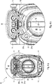
Fig. 3 sind mehrere Ansichten des Reinigungsgeräts 10 mit "verschlossenem" Kabelhaken 40 aus unterschiedlichen Perspektiven gezeigt. Das Bedienelement 21 weist einen sich im Wesentlichen in einer radialen Richtung erstreckenden ersten Abschnitt 21a auf (vgl. insb.Fig. 3c ). Die Richtungsangabe radial bezieht sich auf die kreisförmige Bewegung des Bedienhebels 21 entlang der Kreisbahn 25 (siehe z.B.Fig. 3a ). Das Bedienelement 21 weist außerdem einen zweiten Abschnitt 21b auf, welcher drehbar auf dem ersten Abschnitt angeordnet ist. Der zweite Abschnitt 21b dient als Griffelement und ist so ausgebildet, dass er bei einer Verschwenkbewegung entlang der Kreisbahn 25, beispielsweise beim manuellen Aufrollen des Kabels 30 über die Aufrolltrommel der Aufrolleinrichtung 20, nicht mitdreht. - In der Draufsicht gemäß
Fig. 3a ist zu erkennen, dass das Bedienelement 21 den Kabelhaken 40 in Aufstellrichtung des Reinigungsgeräts 10 betrachtet vollständig überdeckt. Dies ist jedoch nicht zwingend, es ist vielmehr ausreichend, wenn ein Abstand zwischen dem Bedienelement 21 und dem Kabelhaken 40 in vertikaler bzw. horizontaler Richtung eine Größenordnung des Kabeldurchmessers zumindest nicht überschreitet. Ein direkter Kontakt zwischen dem Bedienhebel 21 und dem Kabelhaken 40 in der Verriegelungsstellung ist unerwünscht, da dies den Betrieb der Aufrolleinrichtung 20 behindern würde. Wie in der Seitenansicht gemäßFig. 3b zu erkennen, ist der Bedienhebel 21 in Aufstellrichtung des Reinigungsgeräts 10 betrachtet vollständig oberhalb des Kabelhakens 40 angeordnet. Dies ist ebenfalls nicht zwingend, solange der radiale erste Abschnitt 21a des Bedienelements 21 nicht derart lang ausgebildet ist, dass er an den Kabelhaken 40 anstößt. - In
Fig. 4 ist das Reinigungsgerät 10 mit dem Bedienelement 21 in Freigabestellung gezeigt. Über die Aufrolleinrichtung 20 wird bei einer Verschwenkung des Bedienhebels 21 entlang der Kreisbahn 25 das Kabel 30 aufgerollt. Der Bedienhebel 21 wird um den Griff 12 bewegt und bei einem Abrollen des Kabels 30 schwenkt der Bedienhebel 21 dementsprechend in eine entgegengesetzte Richtung zurück. - Gemäß
Fig. 5 ist der Kabelhaken 40 feststehend an einer Rückseite des Gehäuses 13 ausgebildet und erstreckt sich ausschließlich in einer im Wesentlichen vertikalen Richtung. Der Kabelhaken 40 schließt in etwa bündig ab mit einer Oberseite des Gehäuses 13 ab und ist derart geräumt ausgebildet, dass er eine Vielzahl von Kabelwicklungen aufnimmt. Das am Kabelhaken 40 aufgehängte Kabel 30 verdeckt an der Rückseite des Reinigungsgeräts angeordnete Lüftungsschlitze nicht. -
- 10
- Kabelgebundenes Reinigungsgerät
- 11
- Rollen
- 12
- Griff
- 13
- Gehäuse
- 20
- Aufrolleinrichtung
- 21
- Bedienelement
- 21a
- erster Abschnitt des Bedienelements
- 21b
- zweiter Abschnitt des Bedienelements
- 25
- Kreisbahn
- 30
- Kabel
- 40
- Kabelhaken
- D
- Drehachse
Claims (13)
- Kabelgebundenes Reinigungsgerät (10), insbesondere Sauggerät, mit einer über ein Bedienelement (21) betätigbaren Aufrolleinrichtung (20) für ein Kabel (30) und einem an einer Außenseite des Reinigungsgeräts (10) angeordneten Kabelhaken (40), wobei das Bedienelement (21) in einer Verriegelungsstellung einen Verschluss für den Kabelhaken (40) bildet.
- Kabelgebundenes Reinigungsgerät (10) nach Anspruch 1, dessen Bedienelement (21) zwischen der Verriegelungsstellung und einer Freigabestellung überführbar ist, wobei in der Freigabestellung der Kabelhaken (40) frei zugänglich ist.
- Kabelgebundenes Reinigungsgerät (10) nach Anspruch 2, dessen Bedienelement (21) zwischen der Verriegelungsstellung und der Freigabestellung eine Schwenkbewegung, vorzugsweise eine Schwenkbewegung entlang einer Kreisbahn (25), ausführt.
- Kabelgebundenes Reinigungsgerät (10) nach einem der voranstehenden Ansprüche, dessen Aufrolleinrichtung (20) eine drehbar um eine Drehachse (D) gelagerte Aufrolltrommel zur Aufnahme des Kabels (30) aufweist, wobei das Bedienelement (21) fest mit der Aufrolltrommel verbunden ist.
- Kabelgebundenes Reinigungsgerät (10) nach einem der voranstehenden Ansprüche, dessen Aufrolleinrichtung (20) bei einer Bewegung des Bedienelements (21) entlang der Kreisbahn (25) das Kabel (30) aufrollt.
- Kabelgebundenes Reinigungsgerät (10) nach einem der voranstehenden Ansprüche, dessen Bedienelement (21) einen sich im Wesentlichen in einer radialen Richtung erstreckenden ersten Abschnitt (21a) aufweist.
- Kabelgebundenes Reinigungsgerät (10) nach Anspruch 6, dessen Bedienelement (21) einen drehbar auf dem ersten Abschnitt (21) angeordneten zweiten Abschnitt (21b) aufweist, wobei vorzugsweise der zweite Abschnitt als Griffelement dient.
- Kabelgebundenes Reinigungsgerät (10) nach einem der voranstehenden Ansprüche, dessen Bedienelement (21) als Handkurbel ausgebildet ist.
- Kabelgebundenes Reinigungsgerät (10) nach einem der voranstehenden Ansprüche, mit einem feststehenden Kabelhaken (40).
- Kabelgebundenes Reinigungsgerät (10) nach einem der voranstehenden Ansprüche, dessen Kabelhaken (40) sich im Wesentlichen in vertikaler Richtung erstreckt.
- Kabelgebundenes Reinigungsgerät (10) nach einem der voranstehenden Ansprüche, dessen Bedienelement (21) in der Verriegelungsstellung den Kabelhaken (40) mindestens teilweise, vorzugsweise vollständig, überdeckt.
- Kabelgebundenes Reinigungsgerät (10) nach einem der voranstehenden Ansprüche, dessen Bedienelement (21) in der Verriegelungsstellung einen Abstand zu dem Kabelhaken (40) aufweist, wobei der Abstand vorzugsweise geringer ist als ein Durchmesser des Kabels (30).
- Kabelgebundenes Reinigungsgerät (10) nach einem der voranstehenden Ansprüche, dessen Bedienelement (21) in der Verriegelungsstellung arretierbar ist.
Applications Claiming Priority (1)
| Application Number | Priority Date | Filing Date | Title |
|---|---|---|---|
| DE202019104772.0U DE202019104772U1 (de) | 2019-08-30 | 2019-08-30 | Kabelgebundenes Reinigungsgerät |
Publications (3)
| Publication Number | Publication Date |
|---|---|
| EP3785592A2 true EP3785592A2 (de) | 2021-03-03 |
| EP3785592A3 EP3785592A3 (de) | 2021-03-10 |
| EP3785592B1 EP3785592B1 (de) | 2022-05-18 |
Family
ID=68105479
Family Applications (1)
| Application Number | Title | Priority Date | Filing Date |
|---|---|---|---|
| EP20189394.8A Active EP3785592B1 (de) | 2019-08-30 | 2020-08-04 | Kabelgebundenes reinigungsgerät |
Country Status (3)
| Country | Link |
|---|---|
| EP (1) | EP3785592B1 (de) |
| CN (1) | CN112438655B (de) |
| DE (1) | DE202019104772U1 (de) |
Cited By (1)
| Publication number | Priority date | Publication date | Assignee | Title |
|---|---|---|---|---|
| WO2026041809A3 (de) * | 2024-08-23 | 2026-05-07 | Festool Gmbh | Sauggerät mit einem deckel |
Families Citing this family (1)
| Publication number | Priority date | Publication date | Assignee | Title |
|---|---|---|---|---|
| DE102020113525A1 (de) * | 2020-05-19 | 2021-11-25 | Alfred Kärcher SE & Co. KG | Saugvorrichtung |
Family Cites Families (8)
| Publication number | Priority date | Publication date | Assignee | Title |
|---|---|---|---|---|
| US2594456A (en) * | 1948-10-16 | 1952-04-29 | Hoover Co | Vacuum cleaner |
| US2725588A (en) * | 1952-07-30 | 1955-12-06 | Gen Electric | Combined cord storage reel and air inlet fitting for suction cleaner and the like |
| DE3448046A1 (de) * | 1984-08-17 | 1986-05-28 | Progress-Elektrogeräte Mauz & Pfeiffer GmbH & Co, 7000 Stuttgart | Staubsaugergriff |
| CN1205863A (zh) * | 1997-03-31 | 1999-01-27 | 大宇电子株式会社 | 具有绕线器的卷线筒松开装置的真空吸尘器 |
| DE202011051991U1 (de) * | 2011-11-16 | 2011-11-28 | G. Staehle Gmbh U. Co. Kg | Reinigungsgerät, insbesondere Staubsauger |
| DE102012108649A1 (de) * | 2012-09-14 | 2014-03-20 | Alfred Kärcher Gmbh & Co. Kg | Staubsauger |
| CN206621331U (zh) * | 2016-11-01 | 2017-11-10 | 江苏美的清洁电器股份有限公司 | 手柄组件和具有手柄组件的吸尘器 |
| US10888887B2 (en) * | 2016-11-14 | 2021-01-12 | Briggs & Stratton, Llc | Electric pressure washer with folding handle |
-
2019
- 2019-08-30 DE DE202019104772.0U patent/DE202019104772U1/de active Active
-
2020
- 2020-08-04 EP EP20189394.8A patent/EP3785592B1/de active Active
- 2020-08-28 CN CN202010889648.4A patent/CN112438655B/zh active Active
Cited By (1)
| Publication number | Priority date | Publication date | Assignee | Title |
|---|---|---|---|---|
| WO2026041809A3 (de) * | 2024-08-23 | 2026-05-07 | Festool Gmbh | Sauggerät mit einem deckel |
Also Published As
| Publication number | Publication date |
|---|---|
| EP3785592B1 (de) | 2022-05-18 |
| CN112438655A (zh) | 2021-03-05 |
| DE202019104772U1 (de) | 2019-09-16 |
| CN112438655B (zh) | 2023-08-08 |
| EP3785592A3 (de) | 2021-03-10 |
Similar Documents
| Publication | Publication Date | Title |
|---|---|---|
| EP3789236A1 (de) | Ladestation für ein elektrisch betriebenes fahrzeug | |
| DE102010040787A1 (de) | Ladeeinrichtung für ein Elektrofahrzeug und Verfahren | |
| EP3785592B1 (de) | Kabelgebundenes reinigungsgerät | |
| DE69907062T2 (de) | Schlauchhaspel | |
| WO2013017115A2 (de) | Lagereinrichtung mit kabelführung für ein elektrofahrzeug | |
| DE202009005007U1 (de) | Wickelvorrichtung zum Bedecken von Wandöffnungen oder Fenstern | |
| DE102015009700A1 (de) | Seilwinde und Seiltrommel | |
| DE855594C (de) | Aufwickelvorrichtung fuer Verbindungskabel elektrischer Geraete | |
| DE102005031527A1 (de) | Aufbewahrungseinrichtung für Gartenschlauch | |
| EP1652707A2 (de) | Gerät zum synchronen Aus- uns Einfahren von zwei Drahtabschnitten sowie ein Kraftfahrzeug mit einem solchen Gerät | |
| DE2837467C2 (de) | Bügeleisen mit Kabelaufrollung | |
| DE102012017515B4 (de) | Schließvorrichtung für eine verschiebbare Laderaumabdeckung, Laderaumabdeckung mit einer Schließvorrichtung und Fahrzeug mit einer derartigen Laderaumabdeckung | |
| EP3296132B1 (de) | Spannvorrichtung für eine gleitschutz- oder reifenschutzvorrichtung eines fahrzeugreifens mit einem handauszug | |
| WO2014040785A1 (de) | Staubsauger | |
| DE102019124947A1 (de) | Kabelgebundenes Reinigungsgerät | |
| DE3219570C2 (de) | Gurtwickler für Rolläden, Jalousien, Markisen od.dgl. | |
| DE19957368C2 (de) | Steckdosenvorrichtung | |
| DE102016124535A1 (de) | Markisen-Bürste | |
| DE60100228T2 (de) | Rolladen mit Mittel zum Blockieren einer Rolladenwickelwelle | |
| EP2156773B1 (de) | Staubsauger mit Anreichhilfe | |
| DE3039202C2 (de) | ||
| DE102024204079B3 (de) | Fahrzeugseitiger Kabelhalter und Ladekabelsystem | |
| DE3803007A1 (de) | Gurtwickler fuer rollaeden, jalousien, markisen od. dgl. | |
| DE102018130274A1 (de) | Notraffsystem | |
| DE2325188A1 (de) | Filmaufwickelspule |
Legal Events
| Date | Code | Title | Description |
|---|---|---|---|
| PUAI | Public reference made under article 153(3) epc to a published international application that has entered the european phase |
Free format text: ORIGINAL CODE: 0009012 |
|
| STAA | Information on the status of an ep patent application or granted ep patent |
Free format text: STATUS: THE APPLICATION HAS BEEN PUBLISHED |
|
| PUAL | Search report despatched |
Free format text: ORIGINAL CODE: 0009013 |
|
| AK | Designated contracting states |
Kind code of ref document: A2 Designated state(s): AL AT BE BG CH CY CZ DE DK EE ES FI FR GB GR HR HU IE IS IT LI LT LU LV MC MK MT NL NO PL PT RO RS SE SI SK SM TR |
|
| AX | Request for extension of the european patent |
Extension state: BA ME |
|
| AK | Designated contracting states |
Kind code of ref document: A3 Designated state(s): AL AT BE BG CH CY CZ DE DK EE ES FI FR GB GR HR HU IE IS IT LI LT LU LV MC MK MT NL NO PL PT RO RS SE SI SK SM TR |
|
| AX | Request for extension of the european patent |
Extension state: BA ME |
|
| RIC1 | Information provided on ipc code assigned before grant |
Ipc: A47L 9/26 20060101AFI20210204BHEP Ipc: A47L 5/36 20060101ALI20210204BHEP |
|
| STAA | Information on the status of an ep patent application or granted ep patent |
Free format text: STATUS: REQUEST FOR EXAMINATION WAS MADE |
|
| 17P | Request for examination filed |
Effective date: 20210721 |
|
| RBV | Designated contracting states (corrected) |
Designated state(s): AL AT BE BG CH CY CZ DE DK EE ES FI FR GB GR HR HU IE IS IT LI LT LU LV MC MK MT NL NO PL PT RO RS SE SI SK SM TR |
|
| GRAP | Despatch of communication of intention to grant a patent |
Free format text: ORIGINAL CODE: EPIDOSNIGR1 |
|
| STAA | Information on the status of an ep patent application or granted ep patent |
Free format text: STATUS: GRANT OF PATENT IS INTENDED |
|
| INTG | Intention to grant announced |
Effective date: 20211216 |
|
| GRAS | Grant fee paid |
Free format text: ORIGINAL CODE: EPIDOSNIGR3 |
|
| GRAA | (expected) grant |
Free format text: ORIGINAL CODE: 0009210 |
|
| STAA | Information on the status of an ep patent application or granted ep patent |
Free format text: STATUS: THE PATENT HAS BEEN GRANTED |
|
| AK | Designated contracting states |
Kind code of ref document: B1 Designated state(s): AL AT BE BG CH CY CZ DE DK EE ES FI FR GB GR HR HU IE IS IT LI LT LU LV MC MK MT NL NO PL PT RO RS SE SI SK SM TR |
|
| REG | Reference to a national code |
Ref country code: GB Ref legal event code: FG4D Free format text: NOT ENGLISH |
|
| REG | Reference to a national code |
Ref country code: CH Ref legal event code: EP |
|
| REG | Reference to a national code |
Ref country code: IE Ref legal event code: FG4D Free format text: LANGUAGE OF EP DOCUMENT: GERMAN |
|
| REG | Reference to a national code |
Ref country code: DE Ref legal event code: R096 Ref document number: 502020001122 Country of ref document: DE |
|
| REG | Reference to a national code |
Ref country code: AT Ref legal event code: REF Ref document number: 1492679 Country of ref document: AT Kind code of ref document: T Effective date: 20220615 |
|
| REG | Reference to a national code |
Ref country code: LT Ref legal event code: MG9D |
|
| REG | Reference to a national code |
Ref country code: NL Ref legal event code: MP Effective date: 20220518 |
|
| PG25 | Lapsed in a contracting state [announced via postgrant information from national office to epo] |
Ref country code: SE Free format text: LAPSE BECAUSE OF FAILURE TO SUBMIT A TRANSLATION OF THE DESCRIPTION OR TO PAY THE FEE WITHIN THE PRESCRIBED TIME-LIMIT Effective date: 20220518 Ref country code: PT Free format text: LAPSE BECAUSE OF FAILURE TO SUBMIT A TRANSLATION OF THE DESCRIPTION OR TO PAY THE FEE WITHIN THE PRESCRIBED TIME-LIMIT Effective date: 20220919 Ref country code: NO Free format text: LAPSE BECAUSE OF FAILURE TO SUBMIT A TRANSLATION OF THE DESCRIPTION OR TO PAY THE FEE WITHIN THE PRESCRIBED TIME-LIMIT Effective date: 20220818 Ref country code: NL Free format text: LAPSE BECAUSE OF FAILURE TO SUBMIT A TRANSLATION OF THE DESCRIPTION OR TO PAY THE FEE WITHIN THE PRESCRIBED TIME-LIMIT Effective date: 20220518 Ref country code: LT Free format text: LAPSE BECAUSE OF FAILURE TO SUBMIT A TRANSLATION OF THE DESCRIPTION OR TO PAY THE FEE WITHIN THE PRESCRIBED TIME-LIMIT Effective date: 20220518 Ref country code: HR Free format text: LAPSE BECAUSE OF FAILURE TO SUBMIT A TRANSLATION OF THE DESCRIPTION OR TO PAY THE FEE WITHIN THE PRESCRIBED TIME-LIMIT Effective date: 20220518 Ref country code: GR Free format text: LAPSE BECAUSE OF FAILURE TO SUBMIT A TRANSLATION OF THE DESCRIPTION OR TO PAY THE FEE WITHIN THE PRESCRIBED TIME-LIMIT Effective date: 20220819 Ref country code: FI Free format text: LAPSE BECAUSE OF FAILURE TO SUBMIT A TRANSLATION OF THE DESCRIPTION OR TO PAY THE FEE WITHIN THE PRESCRIBED TIME-LIMIT Effective date: 20220518 Ref country code: BG Free format text: LAPSE BECAUSE OF FAILURE TO SUBMIT A TRANSLATION OF THE DESCRIPTION OR TO PAY THE FEE WITHIN THE PRESCRIBED TIME-LIMIT Effective date: 20220818 |
|
| PG25 | Lapsed in a contracting state [announced via postgrant information from national office to epo] |
Ref country code: RS Free format text: LAPSE BECAUSE OF FAILURE TO SUBMIT A TRANSLATION OF THE DESCRIPTION OR TO PAY THE FEE WITHIN THE PRESCRIBED TIME-LIMIT Effective date: 20220518 Ref country code: PL Free format text: LAPSE BECAUSE OF FAILURE TO SUBMIT A TRANSLATION OF THE DESCRIPTION OR TO PAY THE FEE WITHIN THE PRESCRIBED TIME-LIMIT Effective date: 20220518 Ref country code: LV Free format text: LAPSE BECAUSE OF FAILURE TO SUBMIT A TRANSLATION OF THE DESCRIPTION OR TO PAY THE FEE WITHIN THE PRESCRIBED TIME-LIMIT Effective date: 20220518 Ref country code: IS Free format text: LAPSE BECAUSE OF FAILURE TO SUBMIT A TRANSLATION OF THE DESCRIPTION OR TO PAY THE FEE WITHIN THE PRESCRIBED TIME-LIMIT Effective date: 20220918 |
|
| PG25 | Lapsed in a contracting state [announced via postgrant information from national office to epo] |
Ref country code: SM Free format text: LAPSE BECAUSE OF FAILURE TO SUBMIT A TRANSLATION OF THE DESCRIPTION OR TO PAY THE FEE WITHIN THE PRESCRIBED TIME-LIMIT Effective date: 20220518 Ref country code: SK Free format text: LAPSE BECAUSE OF FAILURE TO SUBMIT A TRANSLATION OF THE DESCRIPTION OR TO PAY THE FEE WITHIN THE PRESCRIBED TIME-LIMIT Effective date: 20220518 Ref country code: RO Free format text: LAPSE BECAUSE OF FAILURE TO SUBMIT A TRANSLATION OF THE DESCRIPTION OR TO PAY THE FEE WITHIN THE PRESCRIBED TIME-LIMIT Effective date: 20220518 Ref country code: ES Free format text: LAPSE BECAUSE OF FAILURE TO SUBMIT A TRANSLATION OF THE DESCRIPTION OR TO PAY THE FEE WITHIN THE PRESCRIBED TIME-LIMIT Effective date: 20220518 Ref country code: EE Free format text: LAPSE BECAUSE OF FAILURE TO SUBMIT A TRANSLATION OF THE DESCRIPTION OR TO PAY THE FEE WITHIN THE PRESCRIBED TIME-LIMIT Effective date: 20220518 Ref country code: DK Free format text: LAPSE BECAUSE OF FAILURE TO SUBMIT A TRANSLATION OF THE DESCRIPTION OR TO PAY THE FEE WITHIN THE PRESCRIBED TIME-LIMIT Effective date: 20220518 Ref country code: CZ Free format text: LAPSE BECAUSE OF FAILURE TO SUBMIT A TRANSLATION OF THE DESCRIPTION OR TO PAY THE FEE WITHIN THE PRESCRIBED TIME-LIMIT Effective date: 20220518 |
|
| REG | Reference to a national code |
Ref country code: DE Ref legal event code: R097 Ref document number: 502020001122 Country of ref document: DE |
|
| PLBE | No opposition filed within time limit |
Free format text: ORIGINAL CODE: 0009261 |
|
| STAA | Information on the status of an ep patent application or granted ep patent |
Free format text: STATUS: NO OPPOSITION FILED WITHIN TIME LIMIT |
|
| PG25 | Lapsed in a contracting state [announced via postgrant information from national office to epo] |
Ref country code: MC Free format text: LAPSE BECAUSE OF FAILURE TO SUBMIT A TRANSLATION OF THE DESCRIPTION OR TO PAY THE FEE WITHIN THE PRESCRIBED TIME-LIMIT Effective date: 20220518 Ref country code: AL Free format text: LAPSE BECAUSE OF FAILURE TO SUBMIT A TRANSLATION OF THE DESCRIPTION OR TO PAY THE FEE WITHIN THE PRESCRIBED TIME-LIMIT Effective date: 20220518 |
|
| 26N | No opposition filed |
Effective date: 20230221 |
|
| PG25 | Lapsed in a contracting state [announced via postgrant information from national office to epo] |
Ref country code: LU Free format text: LAPSE BECAUSE OF NON-PAYMENT OF DUE FEES Effective date: 20220804 |
|
| REG | Reference to a national code |
Ref country code: BE Ref legal event code: MM Effective date: 20220831 |
|
| PG25 | Lapsed in a contracting state [announced via postgrant information from national office to epo] |
Ref country code: SI Free format text: LAPSE BECAUSE OF FAILURE TO SUBMIT A TRANSLATION OF THE DESCRIPTION OR TO PAY THE FEE WITHIN THE PRESCRIBED TIME-LIMIT Effective date: 20220518 |
|
| PG25 | Lapsed in a contracting state [announced via postgrant information from national office to epo] |
Ref country code: IE Free format text: LAPSE BECAUSE OF NON-PAYMENT OF DUE FEES Effective date: 20220804 Ref country code: FR Free format text: LAPSE BECAUSE OF NON-PAYMENT OF DUE FEES Effective date: 20220831 |
|
| PG25 | Lapsed in a contracting state [announced via postgrant information from national office to epo] |
Ref country code: BE Free format text: LAPSE BECAUSE OF NON-PAYMENT OF DUE FEES Effective date: 20220831 |
|
| REG | Reference to a national code |
Ref country code: CH Ref legal event code: PL |
|
| PG25 | Lapsed in a contracting state [announced via postgrant information from national office to epo] |
Ref country code: MK Free format text: LAPSE BECAUSE OF FAILURE TO SUBMIT A TRANSLATION OF THE DESCRIPTION OR TO PAY THE FEE WITHIN THE PRESCRIBED TIME-LIMIT Effective date: 20220511 Ref country code: CY Free format text: LAPSE BECAUSE OF FAILURE TO SUBMIT A TRANSLATION OF THE DESCRIPTION OR TO PAY THE FEE WITHIN THE PRESCRIBED TIME-LIMIT Effective date: 20220511 Ref country code: CH Free format text: LAPSE BECAUSE OF NON-PAYMENT OF DUE FEES Effective date: 20230831 |
|
| PG25 | Lapsed in a contracting state [announced via postgrant information from national office to epo] |
Ref country code: HU Free format text: LAPSE BECAUSE OF FAILURE TO SUBMIT A TRANSLATION OF THE DESCRIPTION OR TO PAY THE FEE WITHIN THE PRESCRIBED TIME-LIMIT; INVALID AB INITIO Effective date: 20200804 |
|
| PG25 | Lapsed in a contracting state [announced via postgrant information from national office to epo] |
Ref country code: CH Free format text: LAPSE BECAUSE OF NON-PAYMENT OF DUE FEES Effective date: 20230831 |
|
| PGRI | Patent reinstated in contracting state [announced from national office to epo] |
Ref country code: CH Effective date: 20240501 |
|
| PG25 | Lapsed in a contracting state [announced via postgrant information from national office to epo] |
Ref country code: CH Free format text: LAPSE BECAUSE OF NON-PAYMENT OF DUE FEES Effective date: 20230831 |
|
| PGRI | Patent reinstated in contracting state [announced from national office to epo] |
Ref country code: CH Effective date: 20240501 |
|
| PG25 | Lapsed in a contracting state [announced via postgrant information from national office to epo] |
Ref country code: MT Free format text: LAPSE BECAUSE OF FAILURE TO SUBMIT A TRANSLATION OF THE DESCRIPTION OR TO PAY THE FEE WITHIN THE PRESCRIBED TIME-LIMIT Effective date: 20220511 |
|
| PG25 | Lapsed in a contracting state [announced via postgrant information from national office to epo] |
Ref country code: BG Free format text: LAPSE BECAUSE OF FAILURE TO SUBMIT A TRANSLATION OF THE DESCRIPTION OR TO PAY THE FEE WITHIN THE PRESCRIBED TIME-LIMIT Effective date: 20220518 |
|
| PG25 | Lapsed in a contracting state [announced via postgrant information from national office to epo] |
Ref country code: BG Free format text: LAPSE BECAUSE OF FAILURE TO SUBMIT A TRANSLATION OF THE DESCRIPTION OR TO PAY THE FEE WITHIN THE PRESCRIBED TIME-LIMIT Effective date: 20220518 |
|
| GBPC | Gb: european patent ceased through non-payment of renewal fee |
Effective date: 20240804 |
|
| PG25 | Lapsed in a contracting state [announced via postgrant information from national office to epo] |
Ref country code: GB Free format text: LAPSE BECAUSE OF NON-PAYMENT OF DUE FEES Effective date: 20240804 |
|
| PGFP | Annual fee paid to national office [announced via postgrant information from national office to epo] |
Ref country code: DE Payment date: 20250819 Year of fee payment: 6 |
|
| PGFP | Annual fee paid to national office [announced via postgrant information from national office to epo] |
Ref country code: IT Payment date: 20250829 Year of fee payment: 6 |
|
| PGFP | Annual fee paid to national office [announced via postgrant information from national office to epo] |
Ref country code: AT Payment date: 20251020 Year of fee payment: 5 |
|
| PGFP | Annual fee paid to national office [announced via postgrant information from national office to epo] |
Ref country code: CH Payment date: 20250901 Year of fee payment: 6 |
|
| PG25 | Lapsed in a contracting state [announced via postgrant information from national office to epo] |
Ref country code: TR Free format text: LAPSE BECAUSE OF FAILURE TO SUBMIT A TRANSLATION OF THE DESCRIPTION OR TO PAY THE FEE WITHIN THE PRESCRIBED TIME-LIMIT Effective date: 20220518 |