EP3785261B1 - Vertikal übersetzender be-/entladerampenmechanismus für eine kalte speicherdaten-speichervorrichtung - Google Patents
Vertikal übersetzender be-/entladerampenmechanismus für eine kalte speicherdaten-speichervorrichtung Download PDFInfo
- Publication number
- EP3785261B1 EP3785261B1 EP19888247.4A EP19888247A EP3785261B1 EP 3785261 B1 EP3785261 B1 EP 3785261B1 EP 19888247 A EP19888247 A EP 19888247A EP 3785261 B1 EP3785261 B1 EP 3785261B1
- Authority
- EP
- European Patent Office
- Prior art keywords
- ramp
- assembly
- lul
- elevator
- disk
- Prior art date
- Legal status (The legal status is an assumption and is not a legal conclusion. Google has not performed a legal analysis and makes no representation as to the accuracy of the status listed.)
- Active
Links
Images


Classifications
-
- G—PHYSICS
- G11—INFORMATION STORAGE
- G11B—INFORMATION STORAGE BASED ON RELATIVE MOVEMENT BETWEEN RECORD CARRIER AND TRANSDUCER
- G11B21/00—Head arrangements not specific to the method of recording or reproducing
- G11B21/02—Driving or moving of heads
- G11B21/12—Raising and lowering; Back-spacing or forward-spacing along track; Returning to starting position otherwise than during transducing operation
-
- G—PHYSICS
- G11—INFORMATION STORAGE
- G11B—INFORMATION STORAGE BASED ON RELATIVE MOVEMENT BETWEEN RECORD CARRIER AND TRANSDUCER
- G11B21/00—Head arrangements not specific to the method of recording or reproducing
- G11B21/16—Supporting the heads; Supporting the sockets for plug-in heads
- G11B21/22—Supporting the heads; Supporting the sockets for plug-in heads while the head is out of operative position
-
- G—PHYSICS
- G11—INFORMATION STORAGE
- G11B—INFORMATION STORAGE BASED ON RELATIVE MOVEMENT BETWEEN RECORD CARRIER AND TRANSDUCER
- G11B5/00—Recording by magnetisation or demagnetisation of a record carrier; Reproducing by magnetic means; Record carriers therefor
- G11B5/48—Disposition or mounting of heads or head supports relative to record carriers ; arrangements of heads, e.g. for scanning the record carrier to increase the relative speed
- G11B5/52—Disposition or mounting of heads or head supports relative to record carriers ; arrangements of heads, e.g. for scanning the record carrier to increase the relative speed with simultaneous movement of head and record carrier, e.g. rotation of head
- G11B5/53—Disposition or mounting of heads on rotating support
- G11B5/531—Disposition of more than one recording or reproducing head on support rotating cyclically around an axis
-
- G—PHYSICS
- G11—INFORMATION STORAGE
- G11B—INFORMATION STORAGE BASED ON RELATIVE MOVEMENT BETWEEN RECORD CARRIER AND TRANSDUCER
- G11B5/00—Recording by magnetisation or demagnetisation of a record carrier; Reproducing by magnetic means; Record carriers therefor
- G11B5/48—Disposition or mounting of heads or head supports relative to record carriers ; arrangements of heads, e.g. for scanning the record carrier to increase the relative speed
- G11B5/54—Disposition or mounting of heads or head supports relative to record carriers ; arrangements of heads, e.g. for scanning the record carrier to increase the relative speed with provision for moving the head into or out of its operative position or across tracks
-
- G—PHYSICS
- G11—INFORMATION STORAGE
- G11B—INFORMATION STORAGE BASED ON RELATIVE MOVEMENT BETWEEN RECORD CARRIER AND TRANSDUCER
- G11B5/00—Recording by magnetisation or demagnetisation of a record carrier; Reproducing by magnetic means; Record carriers therefor
- G11B5/48—Disposition or mounting of heads or head supports relative to record carriers ; arrangements of heads, e.g. for scanning the record carrier to increase the relative speed
- G11B5/4806—Disposition or mounting of heads or head supports relative to record carriers ; arrangements of heads, e.g. for scanning the record carrier to increase the relative speed specially adapted for disk drive assemblies, e.g. assembly prior to operation, hard or flexible disk drives
- G11B5/4833—Structure of the arm assembly, e.g. load beams, flexures, parts of the arm adapted for controlling vertical force on the head
Definitions
- the invention refers to a vertically-translatable load/unload ramp system for a reduced-head hard disk drive, a reduced-head hard disk drive including the load/unload ramp system, and a load/unload ramp system for a reduced-head hard disk drive.
- Embodiments of the invention may relate generally to a reduced-head hard disk drive having an actuator elevator mechanism and particularly to approaches to a vertically translating and rotating load/unload ramp mechanism.
- Embodiments may be used in the context of a multi-disk, reduced read-write head, digital data storage device (DSD) such as a hard disk drive (HDD).
- DSD digital data storage device
- HDD hard disk drive
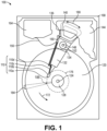
- FIG. 1 a plan view illustrating a conventional HDD 100 is shown in FIG. 1 to aid in describing how a conventional HDD typically operates.
- FIG. 1 illustrates the functional arrangement of components of the HDD 100 including a slider 110b that includes a magnetic read-write head 110a. Collectively, slider 110b and head 110a may be referred to as a head slider.
- the HDD 100 includes at least one head gimbal assembly (HGA) 110 including the head slider, a lead suspension 110c attached to the head slider typically via a flexure, and a load beam 110d attached to the lead suspension 110c.
- the HDD 100 also includes at least one recording medium 120 rotatably mounted on a spindle 124 and a drive motor (not visible) attached to the spindle 124 for rotating the medium 120.
- HGA head gimbal assembly
- the read-write head 110a which may also be referred to as a transducer, includes a write element and a read element for respectively writing and reading information stored on the medium 120 of the HDD 100.
- the medium 120 or a plurality of disk media may be affixed to the spindle 124 with a disk clamp 128.
- the HDD 100 further includes an arm 132 attached to the HGA 110, a carriage 134, a voice-coil motor (VCM) that includes an armature 136 including a voice coil 140 attached to the carriage 134 and a stator 144 including a voice-coil magnet (not visible).
- VCM voice-coil motor
- the armature 136 of the VCM is attached to the carriage 134 and is configured to move the arm 132 and the HGA 110 to access portions of the medium 120, all collectively mounted on a pivot shaft 148 with an interposed pivot bearing assembly 152.
- the carriage 134 may be referred to as an "E-block,” or comb, because the carriage is arranged to carry a ganged array of arms that gives it the appearance of a comb.
- An assembly comprising a head gimbal assembly (e.g., HGA 110) including a flexure to which the head slider is coupled, an actuator arm (e.g., arm 132) and/or load beam to which the flexure is coupled, and an actuator (e.g., the VCM) to which the actuator arm is coupled, may be collectively referred to as a head stack assembly (HSA).
- HSA head stack assembly
- An HSA may, however, include more or fewer components than those described.
- an HSA may refer to an assembly that further includes electrical interconnection components.
- an HSA is the assembly configured to move the head slider to access portions of the medium 120 for read and write operations.
- electrical signals comprising a write signal to and a read signal from the head 110a
- FCA flexible cable assembly
- Interconnection between the flex cable 156 and the head 110a may include an arm-electronics (AE) module 160, which may have an on-board pre-amplifier for the read signal, as well as other read-channel and write-channel electronic components.
- the AE module 160 may be attached to the carriage 134 as shown.
- the flex cable 156 may be coupled to an electrical-connector block 164, which provides electrical communication, in some configurations, through an electrical feed-through provided by an HDD housing 168.
- the HDD housing 168 (or “enclosure base” or “baseplate” or simply “base”), in conjunction with an HDD cover, provides a semi-sealed (or hermetically sealed, in some configurations) protective enclosure for the information storage components of the HDD 100.
- DSP digital-signal processor
- the spinning medium 120 creates a cushion of air that acts as an air-bearing on which the air-bearing surface (ABS) of the slider 110b rides so that the slider 110b flies above the surface of the medium 120 without making contact with a thin magnetic-recording layer in which information is recorded.
- ABS air-bearing surface
- the spinning medium 120 creates a cushion of gas that acts as a gas or fluid bearing on which the slider 110b rides.
- the electrical signal provided to the voice coil 140 of the VCM enables the head 110a of the HGA 110 to access a track 176 on which information is recorded.
- the armature 136 of the VCM swings through an arc 180, which enables the head 110a of the HGA 110 to access various tracks on the medium 120.
- Information is stored on the medium 120 in a plurality of radially nested tracks arranged in sectors on the medium 120, such as sector 184.
- each track is composed of a plurality of sectored track portions (or "track sector") such as sectored track portion 188.
- Each sectored track portion 188 may include recorded information, and a header containing error correction code information and a servo-burst-signal pattern, such as an ABCD-servo-burst-signal pattern, which is information that identifies the track 176.
- a servo-burst-signal pattern such as an ABCD-servo-burst-signal pattern, which is information that identifies the track 176.
- the read element of the head 110a of the HGA 110 reads the servo-burst-signal pattern, which provides a position-error-signal (PES) to the servo electronics, which controls the electrical signal provided to the voice coil 140 of the VCM, thereby enabling the head 110a to follow the track 176.
- PES position-error-signal
- the head 110a Upon finding the track 176 and identifying a particular sectored track portion 188, the head 110a either reads information from the track 176 or writes information to the track 176 depending on instructions received by the disk controller from an external agent, for example, a microprocessor of a computer system.
- an external agent for example, a microprocessor of a computer system.
- An HDD's electronic architecture comprises numerous electronic components for performing their respective functions for operation of an HDD, such as a hard disk controller ("HDC"), an interface controller, an arm electronics module, a data channel, a motor driver, a servo processor, buffer memory, etc. Two or more of such components may be combined on a single integrated circuit board referred to as a "system on a chip" (“SOC"). Several, if not all, of such electronic components are typically arranged on a printed circuit board that is coupled to the bottom side of an HDD, such as to HDD housing 168.
- HDC hard disk controller
- SOC system on a chip
- references herein to a hard disk drive may encompass an information storage device that is at times referred to as a "hybrid drive".
- a hybrid drive refers generally to a storage device having functionality of both a traditional HDD (see, e.g., HDD 100) combined with solid-state storage device (SSD) using non-volatile memory, such as flash or other solid-state (e.g., integrated circuits) memory, which is electrically erasable and programmable.
- the solid-state portion of a hybrid drive may include its own corresponding controller functionality, which may be integrated into a single controller along with the HDD functionality.
- a hybrid drive may be architected and configured to operate and to utilize the solid-state portion in a number of ways, such as, for non-limiting examples, by using the solid-state memory as cache memory, for storing frequently-accessed data, for storing I/O intensive data, and the like. Further, a hybrid drive may be architected and configured essentially as two storage devices in a single enclosure, i.e., a traditional HDD and an SSD, with either one or multiple interfaces for host connection.
- substantially will be understood to describe a feature that is largely or nearly structured, configured, dimensioned, etc., but with which manufacturing tolerances and the like may in practice result in a situation in which the structure, configuration, dimension, etc. is not always or necessarily precisely as stated. For example, describing a structure as "substantially vertical” would assign that term its plain meaning, such that the sidewall is vertical for all practical purposes but may not be precisely at 90 degrees.
- HDD form factor e.g., a 3.5" form factor
- HDD architecture e.g., a 3.5" form factor
- Such a storage device may utilize an articulation mechanism that can move the heads to mate with the different disk surfaces (for a non-limiting example, only 2 heads but 5+ disks for an air drive or 8+ disks for a He drive), where the primary cost savings may come from eliminating the vast majority of the heads in the drive.
- Ramp load/unload (LUL) technology involves a mechanism that moves the head stack assembly (HSA), including the read-write head sliders, away from and off the disks and safely positions them onto a cam-like structure.
- the cam typically includes a shallow ramp on the side closest to the disk.
- the read-write heads are loaded by moving the sliders off the ramp and over the disk surfaces when the disks reach the appropriate rotational speed.
- the terminology used is that the sliders or HSA are "loaded” to or over the disk (i.e., off the ramp) into an operational position, and “unloaded” from the disk (i.e., onto the ramp) such as in an idle position.
- the heads need to be backed off the ramp and then re-engaged to the ramp at the next disk location.
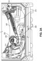
- FIG. 2A is a perspective view illustrating an actuator subsystem in a reduced-head hard disk drive (HDD)
- FIG. 2B is an isolated perspective view illustrating the actuator subsystem of FIG. 2A
- FIG. 2C is an isolated plan view illustrating the actuator subsystem of FIG. 2A , presented as background information but not according to the invention.
- FIGS. 2A-2C collectively illustrate an actuator subsystem comprising a low profile ball screw cam assembly 202 (or “cam 202"), which transforms rotary motion into linear motion, with a stepper motor 204 (or “stepping motor”) disposed therein to form an actuator elevator subassembly, which is disposed within the actuator pivot and pivot bearing of the actuator subsystem (e.g., the "pivot cartridge") and is configured to vertically translate at least one actuator arm 205 (see, e.g., arm 132 of FIG. 1 ) along with a respective HGA 207 (see, e.g., HGA 110 of FIG. 1 ).
- the actuator subsystem for a reduced-head HDD consists of two actuator arm 205 assemblies each with a corresponding HGA 207 (e.g., a modified HSA, in which the actuator arm assemblies translate vertically, or elevate, while the VCM coil 209 may be fixed in the vertical direction) housing a corresponding read-write head 207a (see, e.g., read-write head 110a of FIG. 1 ).
- HGA 207 e.g., a modified HSA, in which the actuator arm assemblies translate vertically, or elevate, while the VCM coil 209 may be fixed in the vertical direction
- the term "reduced-head HDD" is used to refer to an HDD in which the number of read-write heads is less than the number of magnetic-recording disk media surfaces.
- FIGS. 2A-2C further illustrate a flexible cable assembly 208 (“FCA 208"), which is configured to comprise a dynamic vertical "loop" 208a (“FCA vertical loop 208a”) for vertical translation of the end(s) that are coupled to the actuator elevator subassembly and/or another portion of the actuator subsystem.
- FCA vertical loop 208a is in addition to a typical dynamic horizontal loop for horizontal translation purposes for when the actuator to which one end is connected is rotating.
- the actuator subsystem further comprises at least one connector housing 210 for housing an electrical connector for transferring electrical signals (e.g., motor power, sensor signals, etc.) between the actuator elevator subassembly and a ramp elevator assembly (described in more detail elsewhere herein).
- FIGS. 2A-2C further illustrate an arm lock subsystem 206, coupled with or constituent to a coil support assembly 212, configured to mechanically interact with an outer diameter crash stop 211 ("ODCS 211") to lock and unlock the actuator elevator subassembly, as described in more detail elsewhere herein.
- ODCS 211 outer diameter crash stop 211
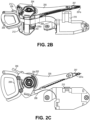
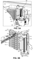
- FIG. 3A is a perspective view illustrating an elevator ramp assembly
- FIG. 3B is a perspective view illustrating a similar elevator ramp assembly (having a slight variation in the motor carriage configuration), presented as background information but not according to the invention.
- the elevator ramp assembly or ramp mechanism illustrated is positioned generally in the area of A-A ( FIG. 2A ) and comprises a multi-disk ramp 310 and a single ramp adapter 302 coupled to a stepper motor carriage 313 of a stepper motor 312.
- the stepper motor 312 drives the vertical translation of the ramp adapter 312, so that the ramp adapter 302 can be moved, synchronously or asynchronously, in conjunction with an actuator elevator subassembly of an actuator subsystem (see, e.g., FIGS. 2A-2C ), such that the ramp adapter 312 can mate with a desired "level" of the ramp 310.
- Each level of the ramp 310 corresponds to a respective disk-ramp portion 3 10a-310n of the ramp 310 (where n is a number that may vary from implementation to implementation based on the number of disks in a given HDD), which corresponds to the position of a respective disk 120 when installed in an HDD.
- the head-stack assembly (HSA) can be driven by the VCM (see, e.g., the VCM of FIG. 1 ) to engage with the ramp adapter 302 and then with the appropriate level of the ramp 310, such that the HSA can ultimately be loaded to an operational position relative to the desired disk of the multi-disk stack.
- the drive mechanism for the ramp adapter 302 comprises the stepper motor 312 with carriage 313 ( FIG. 3A ), 313a ( FIG. 3B ), a lead screw 304 with which the carriage 313 is translatably coupled, and a support or guide rail 306. As the ramp adapter 302 is fixedly coupled with the stepper motor carriage 313, 313a, the ramp adapter 302 is driven by the rotation of the lead screw 304 under the control of the stepper motor 302.
- a proximity sensing subassembly for ramp adapter 302 position sensing and driver feedback purposes, is configured to sense the Z-position (e.g., vertical height) of the carriage 313, 313a and thus the ramp adapter 302.
- the type/form of sensing mechanism used may vary from implementation to implementation. For example, according to an embodiment, sensing is based on the position of the carriage 313, 313a and the ramp adapter 302 relative to a magnetic encoding strip and, ultimately, relative to the disk stack.
- the proximity sensing subassembly comprises a magnetic encoder strip 308 located proximally to at least one corresponding position sensor 314 mounted on the carriage 313, 313a.
- one or more Hall effect sensors are implemented for the position sensor(s) 314, which function in coordination with the closely-positioned magnetic encoder strip 308 mounted on a support structure or stiffener.
- a Hall effect sensor measures the magnitude of a magnetic field, where the output voltage of the sensor is proportional to the magnetic field strength through the sensor.
- other magnetic or non-magnetic based sensing mechanisms may be used for position detection (see, e.g., the inductive sensing mechanism of FIGS. 5A, 5B ).
- a flexible cable assembly (FCA) 316 comprising a vertical "loop” or slack, may be implemented to carry the electrical signals from the position sensor(s) 314 to an electrical connector on connecter housing 210 and onward to some form of controller electronics.
- a fixed load/unload (LUL) ramp such as ramp 310 ( FIGS. 3A-3B ) interfaces with each disk of a multi-disk stack simultaneously, which would therefore require more material (e.g., plastic) to form the multi-level ramp.
- LUL load/unload
- FIG. 4A is a perspective view illustrating a rotatable ramp assembly, presented as background information but not according to the invention.
- Rotatable ramp assembly 400 or ramp mechanism comprises a base 402, on which a rotating latch link 404 is coupled.
- Rotating latch link 404 is configured for rotation (counter-clockwise) about axis 404a by physical interaction with a part of the head stack assembly (HSA), such as by interaction with actuator arm 205 (see, e.g., FIGS. 2A-2C ).
- the latch link 404 is mechanically coupled with a rotating ramp holder 406, to which a LUL ramp 410 is coupled.
- the ramp holder 406 and ramp 410 may be integrated together and formed as a unitary structure, i.e., a single part.
- ramp holder 406 and ramp 410 are driven to overcome magnetic attraction between a magnet 407 fixed to the ramp holder 410 and a latch stop 408, and to rotate clockwise up to a point of contact with the latch stop 408, thereby moving the ramp 410 in and out of engagement with a disk of a multi-disk stack.
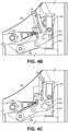
- FIG. 4B is a top view illustrating the rotatable ramp assembly of FIG. 4A in a first operational state within a hard disk drive
- FIG. 4C is a top view illustrating the rotatable ramp assembly of FIG. 4A in a second operational state within a hard disk drive, both presented as background information but not according to the invention;
- the operational state depicted in FIG. 4B shows the LUL ramp assembly 400, positioned generally in the area of A-A ( FIG. 2A ), engaged with a disk (see, e.g., recording medium 120 of FIG.
- FIG. 4C shows the LUL ramp assembly 400 disengaged from a disk 120 of a multi-disk stack, whereby the distal end of the ramp 410 is positioned so that the outer perimeter of the disk 120 is free of (i.e., not disposed within) the channel at the distal end of the ramp 410, and with the HSA shown removed from the ramp 410, in response to a sufficient force applied by the actuator arm 205 to the latch link 404.
- the ramp holder 406 is unlatched from the magnetic attraction of the latch stop 408 with the magnet 407, and in a rotated position with the ramp 410 tip off the disk surface.
- This second operational state of the rotatable ramp assembly 400 allows for disk seek operations (i.e., disk-to-disk translation operations) of the HSA under the control of the actuator elevator subassembly comprising the cam 202 and in-pivot stepper motor 204 ( FIGS. 2A-2C ), according to an embodiment.
- the second operational state of the rotatable ramp assembly 400 allows for vertical translation of the ramp assembly 400, such as described in more detail in reference to FIG. 4D .
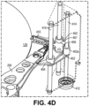
- FIG. 4D is a perspective view illustrating a vertically translatable rotatable ramp assembly within a hard disk drive, presented as background information but not according to the invention.
- the translatable ramp assembly illustrated comprises a ramp assembly (similar to rotatable ramp assembly 400, with like-numbered parts configured and operable the same as or similarly to how described in reference to FIG. 4A ) or ramp mechanism, positioned generally in the area of A-A ( FIG. 2A ), including a plurality of structural interfaces 402a for coupling with a lead screw 414, configured to be driven by a stepper motor 412, and at least one guide rail 416.
- the stepper motor 412 drives the vertical translation of the ramp assembly 400 so that the ramp 410 can be moved, when in the second operational state illustrated in FIG.
- the ramp 410 in conjunction with an actuator elevator subassembly of an actuator subsystem (see, e.g., FIGS. 2A-2C ), such that the ramp 410 can mate with a desired disk 120 of a multi-disk stack.
- the head-stack assembly HSA
- the VCM see, e.g., the VCM of FIG. 1
- the HSA can ultimately be loaded to an operational position relative to the desired disk of the multi-disk stack, such as with the first operational state illustrated FIG. 4B .
- At least one of the interfaces 402a such as an interface 402a associated with the base 402 and/or the latch link 404, comprises a bushing. According to another embodiment, at least one of the interfaces 402a, such as an interface 402a associated with the base 402 and/or the latch link 404, comprises a linear bearing.
- a similar proximity sensing subassembly such as illustrated and described in reference to FIGS. 3A-3B may be implemented for ramp 410 and/or ramp assembly 400 position sensing and driver feedback purposes, and configured to sense the Z-position (e.g., vertical height) of the ramp 410 relative to a magnetic encoder strip and, ultimately, relative to the disk stack.
- a proximity sensing subassembly may comprise a magnetic encoder strip (e.g., magnetic encoder strip 308 of FIGS. 3A-3B ) located proximally to at least one corresponding position sensor (e.g., position sensor(s) 314 of FIGS. 3A-3B ) mounted on the ramp assembly 400.
- FIG. 5A is a perspective view illustrating a vertically translatable articulated ramp assembly in a first operational state
- FIG. 5B is a perspective view illustrating the articulated ramp assembly of FIG. 5A in a second operational state, both according to an embodiment.
- the articulated ramp assembly 500 or ramp mechanism positioned generally in the area of A-A ( FIG. 2A ), comprises a lever portion 502 or member and a ramp portion 510 or member coupled together in a substantially normal relative positioning (although normal relative positioning is not required).
- the lever portion 502 and the ramp portion 510 are coupled with a plurality of interconnected structural elevator interfaces 506 via a plurality of flexures 504, which act like cantilevered spring beams.
- At least one of the elevator interfaces 506 is movably coupled with a lead screw 514, which is configured for driving by a stepper motor 512, while the other elevator interface(s) is movably coupled with a respective guide rail 516.
- the lever portion 502 is configured for translation by physical interaction with a part of the head stack assembly (HSA), such as by interaction with actuator arm 205 (see, e.g., FIGS. 2A-2C ).
- HSA head stack assembly
- FIG. 5A illustrates the articulated ramp assembly 500 in a first operational state within a hard disk drive
- FIG. 5B illustrates the articulated ramp assembly in a second operational state within a hard disk drive
- the operational state depicted in FIG. 5A shows the articulated assembly 500 engaged with a disk (see, e.g., recording medium 120 of FIG. 1 ) of a multi-disk stack, whereby a distal end of the ramp portion 510 is positioned so that the outer perimeter of the disk 120 is disposed within a channel at the distal end of the ramp portion 510, and with the HSA shown parked on the ramp 510.
- This first operational state of the articulated ramp assembly 500 allows the HSA to be loaded onto a disk for various seek/read/write operations to be performed by the HSA under the control of the VCM.
- the operational state depicted in FIG. 5B shows the articulated ramp assembly 500 disengaged from a disk 120 of a multi-disk stack, whereby the distal end of the ramp 510 is positioned so that the outer perimeter of the disk 120 is free of (i.e., not disposed within) the channel at the distal end of the ramp 510.
- the flexures 504 are flexed (e.g., in a state of spring tension) and the interconnected ramp portion 504 is likewise driven rightward, thereby moving the ramp portion 510 out of engagement with a disk of a multi-disk stack.
- the ramp portion 510 is in a translated position with the ramp tip off the disk surface.
- This second operational state of the articulated ramp assembly 500 allows for disk seek operations (i.e., disk-to-disk translation operations) of the HSA under the control of the actuator elevator subassembly comprising the cam 202 and in-pivot stepper motor 204 ( FIGS. 2A-2C ), according to an embodiment.
- the second operational state of the articulated ramp assembly 500 allows for vertical translation of the ramp assembly 500, such as described in more detail elsewhere herein.
- FIGS. 5A-5B depict the flexures 504 in a relaxed or neutral position when the ramp portion 510 is engaged with the disk 120, and in a flexed position (e.g., in a state of spring tension) when the ramp portion 510 is disengaged from the disk 120.
- this arrangement may vary from implementation to implementation, as the articulated ramp assembly 500 may be configured so that the flexures 504 are in a relaxed or neutral position when the ramp portion 510 is disengaged from the disk 120 and in a flexed position when the ramp portion 510 is engaged with the disk 120.
- the articulated ramp assembly 500 is considered a vertically translatable articulated ramp assembly within a hard disk drive, according to an embodiment, in view of the plurality of structural elevator interfaces 506 configured for coupling with a lead screw 514, configured to be driven by a stepper motor 512, and at least one guide rail 516.
- the stepper motor 512 drives the vertical translation of the ramp assembly 500 so that the ramp portion 510 can be moved, when in the second operational state illustrated in FIG. 5B , in conjunction with an actuator elevator subassembly of an actuator subsystem (see, e.g., FIGS.
- the ramp portion 510 can mate with a desired disk 120 of a multi-disk stack.
- the head-stack assembly HSA
- the VCM see, e.g., the VCM of FIG. 1
- the VCM see, e.g., the VCM of FIG. 1
- the HSA can ultimately be loaded to an operational position relative to the desired disk of the multi-disk stack, such as with the first operational state illustrated FIG. 5A .
- at least one of the elevator interfaces 506 may comprise a bushing and/or at least one of the elevator interfaces 506 may comprise a linear bearing.
- a similar proximity sensing subassembly such as illustrated and described in reference to FIGS. 3A-3B may be implemented for ramp assembly 500 position sensing and driver feedback purposes, and configured to sense the Z-position (e.g., vertical height) of the ramp portion 510 relative to a magnetic encoder strip
- a sensor 508 is coupled with a portion of the ramp assembly 500 and positioned as illustrated in FIGS. 5A-5B in order to directly sense the location of the disk edge, rather than sensing the position based on an object remote from the disk stack (e.g., a magnetic encoder strip).
- a non-contact inductive proximity sensor, and associated electronic circuitry 508a is utilized for sensor 508 and is positioned as close to the disk stack as practically feasible.
- inductive sensor 508 relies on the principle of electromagnetic induction and is implemented in the form of one or more coils embedded in a flexible printed circuit (FPC) and/or flexible cable assembly such as a portion of or an electrical extension of FCA 513, which may ultimately tie in with FCA 208 ( FIGS. 2A-2C ).
- FPC flexible printed circuit
- FCA 513 flexible cable assembly
- a coil e.g., an inductor, such as in an LCR circuit comprising an inductor, capacitor, and resistor
- another coil may be used to detect changes in the magnetic field introduced by a metallic object, such as the nickel-plating covering the edge of disk 120.
- a metallic object such as the nickel-plating covering the edge of disk 120 moving past the coil(s) will alter the inductance in the coil and hence the resonant frequency of the LCR circuit electrically coupled to the electronic circuitry 508a, whereby the change in resonant frequency is detected.
- the electronic circuitry 508a then converts this change in resonant frequency to a standard DAC (digital-to-analog converter) output, which can be used for servo control of the stepper motor 512.
- DAC digital-to-analog converter
- the change in resonant frequency of the inductive sensor 508, when moving from media to air gap to media, can be detected and, therefore, the positioning of the ramp assembly 500 relative to the disk stack can likewise be determined.
- the type/form of sensing mechanism used may vary from implementation to implementation.
Landscapes
- Moving Of Heads (AREA)
Claims (11)
- Ein vertikal übersetzbares Lade-/Entlade-Rampensystem, LUL-Rampensystem, für ein Festplattenlaufwerk, HDD, mit reduziertem Kopf, wobei das System eine Rampenanordnung (500) beinhaltet,
wobei die Rampenanordnung (500) Folgendes beinhaltet:ein übersetzbares LUL-Rampenelement (510);gekennzeichnet durchein übersetzbares Hebelelement (502), das mit dem LUL-Rampenelement (510) gekoppelt ist und zur mechanischen Interaktion mit einer Kopfstapelanordnung, HSA, konfiguriert ist;eine Vielzahl von verbundenen strukturellen Aufzugschnittstellen (506), die mit dem LUL-Rampenelement (510) gekoppelt sind; undeine Vielzahl von Biegungen (504), die die Aufzugschnittstellen (506) mit dem LUL-Rampenelement (510) verbinden,wobei die Rampenanordnung (500) einen ersten Betriebszustand und einen zweiten Betriebszustand aufweist;wobei in dem ersten Betriebszustand:eine Nullkraft oder vernachlässigbare Kraft durch die HSA auf das Hebelelement (502) ausgeübt wird; undein distales Ende des LUL-Rampenelements (510) so positioniert ist, dass ein äußerer Umfang einer Aufnahmescheibe (120) eines HDDs innerhalb eines Kanals an dem distalen Ende des LUL-Rampenelements (510) angeordnet ist; undwobei in dem zweiten Betriebszustand:eine ausreichende Kraft durch die HSA auf das Hebelelement (502) aufgebracht wird; undein distales Ende des LUL-Rampenelements (510) so positioniert ist, dass ein äußerer Umfang einer Aufnahmescheibe (120) eines HDDs frei von einem Kanal an dem distalen Ende des LUL-Rampenelements (510) ist. - LUL-Rampensystem gemäß Anspruch 1, wobei sich in dem ersten Betriebszustand der Rampenanordnung (500)
die Vielzahl von Biegungen (504) entweder in einem gelockerten Zustand oder in einem angespannten Zustand befindet. - LUL-Rampensystem gemäß Anspruch 1, wobei sich in dem zweiten Betriebszustand der Rampenanordnung (500)
die Vielzahl von Biegungen (504) entweder in einem gelockerten Zustand oder in einem angespannten Zustand befindet. - LUL-Rampensystem gemäß Anspruch 1, wobei sich in dem zweiten Betriebszustand der Rampenanordnung (500)
das Hebelelement (502) in Kontakt mit einem Sensor (508) befindet, der konfiguriert ist, um zu detektieren, dass die HSA das Hebelelement (502) eine gewisse Distanz übersetzt hat, um den äußeren Umfang der Aufnahmescheibe von dem Kanal an dem distalen Ende des LUL-Rampenelements (510) zu befreien. - LUL-Rampensystem gemäß Anspruch 1, das ferner Folgendes beinhaltet:
einen Schrittmotor (512), der konfiguriert ist, um die Drehung einer Leitspindel (514) anzutreiben, um die Übersetzung der Rampenanordnung (500) entlang einer Achse der Leitspindel (514) anzutreiben. - LUL-Rampensystem gemäß Anspruch 1, das ferner Folgendes beinhaltet:eine oder mehrere Führungsschienen (516), die konfiguriert sind, um sich mit einer jeweiligen entsprechenden Aufzugschnittstelle (506) der Vielzahl von strukturellen Aufzugschnittstellen (506) der Rampenanordnung (500) über eine Schnittstelle zu verbinden; undeinen Schrittmotor (512), der konfiguriert ist, um die Drehung einer Leitspindel (514) anzutreiben, um die Übersetzung der Rampenanordnung (500) entlang einer Achse der Leitspindel (514) und durch Unterstützung von der einen oder den mehreren Führungsschienen (516) anzutreiben.
- LUL-Rampensystem gemäß Anspruch 6, wobei:eine erste Aufzugschnittstelle der Vielzahl von strukturellen Aufzugschnittstellen (506) um eine erste Führungsschiene der einen oder der mehreren Führungsschienen (516) positioniert ist;eine zweite intern gewundene Aufzugschnittstelle der Vielzahl von strukturellen Aufzugschnittstellen (506) um die Leitspindel (514) positioniert ist; undeine dritte Aufzugschnittstelle der Vielzahl von strukturellen Aufzugschnittstellen (506) um eine zweite Führungsschiene der einen oder der mehreren Führungsschienen (516) positioniert ist.
- LUL-Rampensystem gemäß Anspruch 7, wobei:eine erste Biegung der Vielzahl von Biegungen (504) zwischen der ersten Aufzugschnittstelle und der zweiten Aufzugschnittstelle positioniert ist; undeine zweite Biegung der Vielzahl von Biegungen (504) zwischen der zweiten Aufzugschnittstelle und der dritten Aufzugschnittstelle positioniert ist.
- LUL-Rampensystem gemäß Anspruch 1, wobei die Rampenanordnung (500) ferner Folgendes beinhaltet:
einen Näherungssensor (508), der proximal zu einem distalen Ende des LUL-Rampenelements (510) positioniert ist und zum Detektieren einer vertikalen Position der Rampenanordnung (500), die jeder Aufzeichnungsscheibe (120) eines Stapels mehrerer Scheiben eines HDDs entspricht, konfiguriert ist. - Ein Festplattenlaufwerk, HDD, mit reduziertem Kopf, das Folgendes beinhaltet:eine Vielzahl von n aufzeichnenden Scheibenmedien (120), die drehbar auf einer Spindel (124) befestigt ist;eine Vielzahl von weniger als 2n Kopfschiebern, die jeweils einen Lese-Schreib-Wandler (110a) beinhalten, der konfiguriert ist, um auf mindestens zwei Scheibenmedien (120) der Vielzahl von Scheibenmedien (120) zu lesen und auf diese zu schreiben;eine Aktuatoranordnung, die konfiguriert ist, um die Vielzahl von Kopfschiebern zu bewegen, um auf Abschnitte der mindestens zwei Scheibenmedien (120) zuzugreifen;eine Aktuatoraufzugunteranordnung, die konfiguriert ist, um die Aktuatoranordnung zu bewegen, um auf die mindestens zwei Scheibenmedien (120) zuzugreifen; unddas LUL-Rampensystem gemäß einem der vorhergehenden Ansprüche, wobei das übersetzbare Hebelelement (502) zur mechanischen Interaktion mit einer Kopfstapelanordnung, HSA, konfiguriert ist, die die Vielzahl von Kopfschiebern beherbergt.
- Ein Festplattenlaufwerk, das das LUL-Rampensystem gemäß Anspruch 1 beinhaltet.
Applications Claiming Priority (2)
| Application Number | Priority Date | Filing Date | Title |
|---|---|---|---|
| PCT/US2019/042495 WO2021011011A1 (en) | 2019-07-18 | 2019-07-18 | Vertically translating load/unload ramp mechanism for cold storage data storage device |
| US16/516,211 US10803891B1 (en) | 2019-07-18 | 2019-07-18 | Vertically translating load/unload ramp mechanism for cold storage data storage device |
Publications (3)
| Publication Number | Publication Date |
|---|---|
| EP3785261A4 EP3785261A4 (de) | 2021-03-03 |
| EP3785261A1 EP3785261A1 (de) | 2021-03-03 |
| EP3785261B1 true EP3785261B1 (de) | 2024-09-18 |
Family
ID=72750059
Family Applications (1)
| Application Number | Title | Priority Date | Filing Date |
|---|---|---|---|
| EP19888247.4A Active EP3785261B1 (de) | 2019-07-18 | 2019-07-18 | Vertikal übersetzender be-/entladerampenmechanismus für eine kalte speicherdaten-speichervorrichtung |
Country Status (4)
| Country | Link |
|---|---|
| US (1) | US10803891B1 (de) |
| EP (1) | EP3785261B1 (de) |
| CN (1) | CN112534501B (de) |
| WO (1) | WO2021011011A1 (de) |
Families Citing this family (20)
| Publication number | Priority date | Publication date | Assignee | Title |
|---|---|---|---|---|
| US11043235B2 (en) | 2018-04-27 | 2021-06-22 | Seagate Technology Llc | Assembly that enables reduction in disk to disk spacing |
| US11423927B2 (en) | 2018-04-27 | 2022-08-23 | Seagate Technology Llc | Assembly that enables reduction in disk to disk spacing |
| CN111480199B (zh) * | 2018-07-19 | 2021-08-20 | 西部数据技术公司 | 垂直地平移用于冷存储数据存储装置的加载/卸载坡道机构 |
| US11094347B1 (en) * | 2020-04-30 | 2021-08-17 | Seagate Technology Llc | Split ramp for data storage devices |
| US11308984B2 (en) | 2020-06-24 | 2022-04-19 | Seagate Technology Llc | Retractable ramp for data storage devices |
| US11348610B1 (en) * | 2021-02-01 | 2022-05-31 | Seagate Technology Llc | Movable ramp with arm engaging bracket for an elevator drive on a magnetic disc recording device |
| US11315592B1 (en) | 2021-02-10 | 2022-04-26 | Seagate Technology Llc | Adjusting HGA z-height via HSA elevator using head/actuator feedback |
| US11875830B2 (en) | 2021-02-10 | 2024-01-16 | Seagate Technology Llc | Adjusting HGA z-height via HSA elevator using head/actuator feedback |
| US11948612B2 (en) | 2021-04-19 | 2024-04-02 | Seagate Technology Llc | Zero skew elevator system |
| US11348611B1 (en) | 2021-04-19 | 2022-05-31 | Seagate Technology Llc | Zero skew elevator system |
| US11443763B1 (en) | 2021-06-18 | 2022-09-13 | Seagate Technology Llc | Disk drive with multiple actuators on a pivot axis |
| US11361787B1 (en) * | 2021-07-30 | 2022-06-14 | Seagate Technology Llc | Zero skew disk drive with dual actuators |
| US11488624B1 (en) | 2021-09-20 | 2022-11-01 | Seagate Technology Llc | Ball bearing cartridge for linear actuator |
| JP2023046037A (ja) * | 2021-09-22 | 2023-04-03 | 株式会社東芝 | ディスク装置 |
| US11817125B1 (en) | 2021-10-14 | 2023-11-14 | Seagate Technology Llc | Calibratable brake crawler for multi-disk drives |
| US11468909B1 (en) | 2021-11-02 | 2022-10-11 | Seagate Technology Llc | Zero skew with ultrasonic piezoelectric swing suspension |
| US11430472B1 (en) | 2021-11-17 | 2022-08-30 | Seagate Technology Llc | Triple magnet linear actuator motor |
| US11900965B2 (en) | 2022-02-14 | 2024-02-13 | Seagate Technology Llc | Z-height control for disc drive using servo wedge timing |
| US12354631B2 (en) | 2023-05-17 | 2025-07-08 | Western Digital Technologies, Inc. | Ramp support for a magnetic storage device |
| US12542162B1 (en) | 2024-08-15 | 2026-02-03 | Seagate Technology Llc | Crash stop that includes silicone rubber for a data storage device, and related articles, systems, and methods |
Family Cites Families (60)
| Publication number | Priority date | Publication date | Assignee | Title |
|---|---|---|---|---|
| BE543903A (de) | 1954-12-24 | |||
| NL212389A (de) | 1955-02-02 | |||
| NL212805A (de) | 1955-12-09 | |||
| DE1508049A1 (de) | 1966-05-05 | 1969-10-02 | Metallgesellschaft Ag | Verfahren zur Verhuetung oxydischer eisenhaltiger Erze |
| US3940794A (en) | 1974-06-19 | 1976-02-24 | International Business Machines Corporation | Stacked flexible record disk storage apparatus having enhanced disk separation |
| US4164767A (en) | 1977-03-04 | 1979-08-14 | Burroughs Corporation | Mass storage device |
| DE2759065A1 (de) | 1977-12-30 | 1979-07-12 | Ibm Deutschland | Feder-masse-schwingungssystem |
| US4742410A (en) | 1983-12-16 | 1988-05-03 | Josephine County Technology, Inc. | Disk drive system with head protection mechanism |
| US4566087A (en) | 1984-05-22 | 1986-01-21 | Casdade Systems Incorporated | Digital optical disk system |
| US4884261A (en) | 1985-07-29 | 1989-11-28 | Tandon Corporation | Storage media transducer loading/unloading and carriage lock mechanism |
| JPH07118140B2 (ja) | 1985-12-11 | 1995-12-18 | 富士写真フイルム株式会社 | 磁気デイスクカ−トリツジの装脱装置 |
| JPH03276475A (ja) | 1990-03-27 | 1991-12-06 | Matsushita Electric Ind Co Ltd | 磁気ディスク装置 |
| US5023737A (en) | 1990-04-05 | 1991-06-11 | Seagate Technology, Inc. | Disc drive slider lifter using shape memory materials |
| JPH04167276A (ja) | 1990-10-30 | 1992-06-15 | Teac Corp | 磁気ディスク装置 |
| JP2642002B2 (ja) | 1991-06-17 | 1997-08-20 | 茨城日本電気株式会社 | 磁気ディスク装置 |
| JP2619174B2 (ja) * | 1992-05-15 | 1997-06-11 | 富士通株式会社 | 磁気ディスク装置 |
| US5467238A (en) * | 1993-07-06 | 1995-11-14 | Quantum Corporation | Cleaning apparatus for heads of data storage disks |
| WO1996036045A1 (en) * | 1995-05-10 | 1996-11-14 | Iomega Corporation | Head loading mechanism for a disk drive |
| US5831795A (en) | 1995-05-10 | 1998-11-03 | Iomega Corporation | Head loading mechanism for a disk drive |
| US5875074A (en) | 1997-04-18 | 1999-02-23 | Quinta Corporation | Adjustable head loading apparatus |
| JP3111038B2 (ja) * | 1997-05-07 | 2000-11-20 | インターナショナル・ビジネス・マシーンズ・コーポレ−ション | 情報記録再生装置用ランプ及び情報記録再生装置 |
| US6057988A (en) | 1997-07-02 | 2000-05-02 | International Business Machines Corporation | Adjustable head suspension load/unload lift cam assembly |
| JP2000163899A (ja) | 1998-11-30 | 2000-06-16 | Fujitsu Ltd | 記録ディスク駆動装置 |
| US6480361B1 (en) | 1999-05-07 | 2002-11-12 | Seagate Technologies Llc | Movable load ramps and crash stop for a disc drive |
| US6212045B1 (en) | 1999-05-14 | 2001-04-03 | Guzik Technical Enterprises | Method and apparatus for loading a magnetic head onto a magnetic disk |
| US6473270B1 (en) * | 1999-08-25 | 2002-10-29 | Seagate Technologies Llc | Actuator shock snubber |
| US7085104B1 (en) * | 1999-10-06 | 2006-08-01 | Western Digital (Fremont), Inc. | Low profile head gimbal assembly with shock limiting and load/unload capability |
| JP2002133827A (ja) * | 2000-10-27 | 2002-05-10 | Internatl Business Mach Corp <Ibm> | ディスク・ドライブ装置、ハード・ディスク・ドライブおよびハード・ディスク・ドライブの筐体 |
| KR100373750B1 (ko) | 2000-12-05 | 2003-02-26 | 삼성전자주식회사 | 디스크 드라이브의 엑추에이터 로딩/언로딩장치 |
| US6693773B1 (en) | 2001-03-30 | 2004-02-17 | Western Digital Technologies, Inc. | Disk drive having a vertically adjustable ramp load |
| US6452753B1 (en) * | 2001-08-06 | 2002-09-17 | Maxtor Corporation | Universal load/unload ramp |
| US20050280945A1 (en) * | 2004-06-16 | 2005-12-22 | Duvall Matthew G | Fluidic stripper assembly with load/unload ramp |
| KR100604872B1 (ko) * | 2004-06-24 | 2006-07-31 | 삼성전자주식회사 | 정보 저장 장치의 헤드 파킹용 램프 |
| US7283318B2 (en) | 2004-06-24 | 2007-10-16 | Hewlett-Packard Development Company, L.P. | Position sensor |
| US7644493B2 (en) | 2004-07-02 | 2010-01-12 | Seagate Technology Llc | Adjustable head stack comb |
| KR100585167B1 (ko) * | 2004-12-07 | 2006-06-01 | 삼성전자주식회사 | 하드 디스크 드라이브의 액츄에이터 이송용 쉬핑 콤 |
| JP2006209901A (ja) * | 2005-01-31 | 2006-08-10 | Fujitsu Ltd | 情報記憶装置 |
| JP2006318519A (ja) * | 2005-05-10 | 2006-11-24 | Hitachi Global Storage Technologies Netherlands Bv | 磁気ディスク装置 |
| JP2007018551A (ja) | 2005-07-05 | 2007-01-25 | Hitachi Global Storage Technologies Netherlands Bv | 磁気ディスク装置 |
| KR100734276B1 (ko) * | 2005-10-10 | 2007-07-02 | 삼성전자주식회사 | Hsa 보호부재 및 이를 이용하여 하드디스크 드라이브에hsa를 장착하는 방법 |
| KR100734295B1 (ko) | 2005-12-16 | 2007-07-02 | 삼성전자주식회사 | 하드 디스크 드라이브의 파킹 램프 및 이를 구비한 하드디스크 드라이브 |
| US7813078B1 (en) | 2006-04-05 | 2010-10-12 | Seagate Technology Llc | Disk drive load/unload ramp with integrated air features |
| KR20090106815A (ko) * | 2008-04-07 | 2009-10-12 | 삼성전자주식회사 | 헤드 파킹용 램프와 이를 구비한 하드 디스크 드라이브 |
| US20090279199A1 (en) | 2008-05-12 | 2009-11-12 | Samsung Electronics Co., Ltd. | Method and apparatus for reducing slider contact probability in a load-unload (LUL) hard disk drive |
| US7986491B2 (en) * | 2008-10-09 | 2011-07-26 | Hitachi Global Storage Technologies Netherlands B.V. | Hard disk drive with disk separator for creating axial gaps between disks for access by read/write heads |
| US8112580B2 (en) | 2009-01-19 | 2012-02-07 | Hitachi Global Storage Technologies Netherlands B.V. | Disk drive having multiple disk surfaces accessible by a read/write head and nonvolatile memory for continuous data transfer |
| US8208215B2 (en) | 2009-02-10 | 2012-06-26 | Hitachi Global Storage Technologies Netherlands, B.V. | Techniques for emulating sequential device with constrained disk drive |
| JP4886882B2 (ja) | 2010-06-30 | 2012-02-29 | 株式会社東芝 | ヘッドスタックアッセンブリおよびこれを備えたディスク駆動装置 |
| US9025277B1 (en) | 2013-10-10 | 2015-05-05 | HGST Netherlands B.V. | Hard disk drive having multiple disk stacks on a rotatable platform |
| US8958173B1 (en) | 2013-10-17 | 2015-02-17 | HGST Netherlands B.V. | Hard disk drive having multiple movable disk stacks on a guide rail |
| US8958172B1 (en) | 2013-10-17 | 2015-02-17 | HGST Netherlands B.V. | Multiple disk stack, single actuator hard disk drive |
| US8824094B1 (en) | 2013-10-18 | 2014-09-02 | HGST Netherlands B.V. | Hard disk drive having multiple disk stacks and a movable head stack assembly |
| US9218833B1 (en) | 2014-11-19 | 2015-12-22 | HGST Netherlands B.V. | Load/unload ramps for multiple disk-stack, shared actuator hard disk drive |
| US9183862B1 (en) * | 2014-11-19 | 2015-11-10 | HGST Netherlands B.V. | Load/unload ramps for multiple disk-stack, shared actuator hard disk drive |
| US9552835B1 (en) | 2016-06-30 | 2017-01-24 | HGST Netherlands B.V. | Actuator limiters for multiple disk-stack, shared actuator hard disk drive |
| US9704521B1 (en) | 2016-06-30 | 2017-07-11 | Western Digital Technologies, Inc. | Actuator limiters for multiple disk-stack, shared actuator hard disk drive |
| US10269380B1 (en) * | 2017-11-14 | 2019-04-23 | Seagate Technology Llc | Disk drive having multiple disks accessible by a reduced number of read/write heads |
| US10811045B2 (en) | 2018-04-27 | 2020-10-20 | Seagate Technology Llc | Assembly that enables reduction in disk to disk spacing |
| CN111480199B (zh) * | 2018-07-19 | 2021-08-20 | 西部数据技术公司 | 垂直地平移用于冷存储数据存储装置的加载/卸载坡道机构 |
| US10811044B2 (en) | 2018-07-19 | 2020-10-20 | Western Digital Technologies, Inc. | In-pivot stepper motor for ball screw cam elevator mechanism for cold storage data storage device |
-
2019
- 2019-07-18 EP EP19888247.4A patent/EP3785261B1/de active Active
- 2019-07-18 WO PCT/US2019/042495 patent/WO2021011011A1/en not_active Ceased
- 2019-07-18 CN CN201980006325.1A patent/CN112534501B/zh active Active
- 2019-07-18 US US16/516,211 patent/US10803891B1/en active Active
Also Published As
| Publication number | Publication date |
|---|---|
| US10803891B1 (en) | 2020-10-13 |
| EP3785261A4 (de) | 2021-03-03 |
| WO2021011011A1 (en) | 2021-01-21 |
| EP3785261A1 (de) | 2021-03-03 |
| CN112534501A (zh) | 2021-03-19 |
| CN112534501B (zh) | 2022-10-25 |
Similar Documents
| Publication | Publication Date | Title |
|---|---|---|
| US10971178B2 (en) | Vertically translating load/unload ramp mechanism for cold storage data storage device | |
| EP3785261B1 (de) | Vertikal übersetzender be-/entladerampenmechanismus für eine kalte speicherdaten-speichervorrichtung | |
| US10930307B2 (en) | Piezoelectric-based locking of actuator elevator mechanism for cold storage data storage device | |
| US11031037B1 (en) | System for disk-to-disk access for reduced-head data storage device | |
| US11935560B2 (en) | Hard disk drive multiple contact disk clamp | |
| US10916271B1 (en) | Eliminating lead screw hysteresis for vertically translating load/unload ramp mechanism for data storage device | |
| US10943614B1 (en) | Load/unload ramp mechanism for reduced cracking | |
| US11955139B2 (en) | Hard disk drive multiple contact disk spindle motor hub flange | |
| CN113496711B (zh) | 具有型锻凸台插入件的型锻板组合件 | |
| JP7631470B2 (ja) | ハードディスクドライブのマルチディスクパック積層構造 | |
| US20250201273A1 (en) | Hard disk drive disk media curvature mitigation | |
| US11869541B1 (en) | Load/unload ramp for high-capacity hard disk drive | |
| US12283292B2 (en) | Hard disk drive idle sweep for thermal asperity avoidance | |
| US20240194222A1 (en) | Pivot-to-enclosure fastening for reducing torsional vibration of actuator coil in hard disk drive | |
| US12322422B1 (en) | Servo-write for magnetic disk media archival data storage system | |
| US20250266059A1 (en) | Fine actuator reaction force cancellation flexible suspension | |
| US12431162B2 (en) | Rotating electromagnet for removable disk clamp | |
| CN118173131A (zh) | 用于减小硬盘驱动器中致动器线圈的扭转振动的枢轴至壳体紧固 |
Legal Events
| Date | Code | Title | Description |
|---|---|---|---|
| STAA | Information on the status of an ep patent application or granted ep patent |
Free format text: STATUS: UNKNOWN |
|
| STAA | Information on the status of an ep patent application or granted ep patent |
Free format text: STATUS: THE INTERNATIONAL PUBLICATION HAS BEEN MADE |
|
| PUAI | Public reference made under article 153(3) epc to a published international application that has entered the european phase |
Free format text: ORIGINAL CODE: 0009012 |
|
| STAA | Information on the status of an ep patent application or granted ep patent |
Free format text: STATUS: REQUEST FOR EXAMINATION WAS MADE |
|
| 17P | Request for examination filed |
Effective date: 20200604 |
|
| A4 | Supplementary search report drawn up and despatched |
Effective date: 20201015 |
|
| AK | Designated contracting states |
Kind code of ref document: A1 Designated state(s): AL AT BE BG CH CY CZ DE DK EE ES FI FR GB GR HR HU IE IS IT LI LT LU LV MC MK MT NL NO PL PT RO RS SE SI SK SM TR |
|
| AX | Request for extension of the european patent |
Extension state: BA ME |
|
| RAP1 | Party data changed (applicant data changed or rights of an application transferred) |
Owner name: WESTERN DIGITAL TECHNOLOGIES, INC. |
|
| RIN1 | Information on inventor provided before grant (corrected) |
Inventor name: MYERS, DAVID Inventor name: JACOBY, JON |
|
| DAV | Request for validation of the european patent (deleted) | ||
| DAX | Request for extension of the european patent (deleted) | ||
| REG | Reference to a national code |
Ref country code: DE Free format text: PREVIOUS MAIN CLASS: G11B0005550000 Ref country code: DE Ref legal event code: R079 Ref document number: 602019059263 Country of ref document: DE Free format text: PREVIOUS MAIN CLASS: G11B0005550000 Ipc: G11B0005480000 |
|
| GRAP | Despatch of communication of intention to grant a patent |
Free format text: ORIGINAL CODE: EPIDOSNIGR1 |
|
| STAA | Information on the status of an ep patent application or granted ep patent |
Free format text: STATUS: GRANT OF PATENT IS INTENDED |
|
| RIC1 | Information provided on ipc code assigned before grant |
Ipc: G11B 21/12 20060101ALI20240410BHEP Ipc: G11B 21/22 20060101ALI20240410BHEP Ipc: G11B 5/54 20060101ALI20240410BHEP Ipc: H02K 21/12 20060101ALI20240410BHEP Ipc: G11B 21/02 20060101ALI20240410BHEP Ipc: G11B 5/48 20060101AFI20240410BHEP |
|
| INTG | Intention to grant announced |
Effective date: 20240424 |
|
| P01 | Opt-out of the competence of the unified patent court (upc) registered |
Effective date: 20240515 |
|
| GRAS | Grant fee paid |
Free format text: ORIGINAL CODE: EPIDOSNIGR3 |
|
| GRAA | (expected) grant |
Free format text: ORIGINAL CODE: 0009210 |
|
| STAA | Information on the status of an ep patent application or granted ep patent |
Free format text: STATUS: THE PATENT HAS BEEN GRANTED |
|
| AK | Designated contracting states |
Kind code of ref document: B1 Designated state(s): AL AT BE BG CH CY CZ DE DK EE ES FI FR GB GR HR HU IE IS IT LI LT LU LV MC MK MT NL NO PL PT RO RS SE SI SK SM TR |
|
| REG | Reference to a national code |
Ref country code: GB Ref legal event code: FG4D |
|
| REG | Reference to a national code |
Ref country code: CH Ref legal event code: EP |
|
| REG | Reference to a national code |
Ref country code: DE Ref legal event code: R096 Ref document number: 602019059263 Country of ref document: DE |
|
| REG | Reference to a national code |
Ref country code: IE Ref legal event code: FG4D |
|
| REG | Reference to a national code |
Ref country code: LT Ref legal event code: MG9D |
|
| PG25 | Lapsed in a contracting state [announced via postgrant information from national office to epo] |
Ref country code: NO Free format text: LAPSE BECAUSE OF FAILURE TO SUBMIT A TRANSLATION OF THE DESCRIPTION OR TO PAY THE FEE WITHIN THE PRESCRIBED TIME-LIMIT Effective date: 20241218 |
|
| PG25 | Lapsed in a contracting state [announced via postgrant information from national office to epo] |
Ref country code: GR Free format text: LAPSE BECAUSE OF FAILURE TO SUBMIT A TRANSLATION OF THE DESCRIPTION OR TO PAY THE FEE WITHIN THE PRESCRIBED TIME-LIMIT Effective date: 20241219 Ref country code: FI Free format text: LAPSE BECAUSE OF FAILURE TO SUBMIT A TRANSLATION OF THE DESCRIPTION OR TO PAY THE FEE WITHIN THE PRESCRIBED TIME-LIMIT Effective date: 20240918 |
|
| PG25 | Lapsed in a contracting state [announced via postgrant information from national office to epo] |
Ref country code: BG Free format text: LAPSE BECAUSE OF FAILURE TO SUBMIT A TRANSLATION OF THE DESCRIPTION OR TO PAY THE FEE WITHIN THE PRESCRIBED TIME-LIMIT Effective date: 20240918 |
|
| PG25 | Lapsed in a contracting state [announced via postgrant information from national office to epo] |
Ref country code: LV Free format text: LAPSE BECAUSE OF FAILURE TO SUBMIT A TRANSLATION OF THE DESCRIPTION OR TO PAY THE FEE WITHIN THE PRESCRIBED TIME-LIMIT Effective date: 20240918 |
|
| PG25 | Lapsed in a contracting state [announced via postgrant information from national office to epo] |
Ref country code: HR Free format text: LAPSE BECAUSE OF FAILURE TO SUBMIT A TRANSLATION OF THE DESCRIPTION OR TO PAY THE FEE WITHIN THE PRESCRIBED TIME-LIMIT Effective date: 20240918 |
|
| REG | Reference to a national code |
Ref country code: NL Ref legal event code: MP Effective date: 20240918 |
|
| PG25 | Lapsed in a contracting state [announced via postgrant information from national office to epo] |
Ref country code: RS Free format text: LAPSE BECAUSE OF FAILURE TO SUBMIT A TRANSLATION OF THE DESCRIPTION OR TO PAY THE FEE WITHIN THE PRESCRIBED TIME-LIMIT Effective date: 20241218 |
|
| PG25 | Lapsed in a contracting state [announced via postgrant information from national office to epo] |
Ref country code: RS Free format text: LAPSE BECAUSE OF FAILURE TO SUBMIT A TRANSLATION OF THE DESCRIPTION OR TO PAY THE FEE WITHIN THE PRESCRIBED TIME-LIMIT Effective date: 20241218 Ref country code: NO Free format text: LAPSE BECAUSE OF FAILURE TO SUBMIT A TRANSLATION OF THE DESCRIPTION OR TO PAY THE FEE WITHIN THE PRESCRIBED TIME-LIMIT Effective date: 20241218 Ref country code: LV Free format text: LAPSE BECAUSE OF FAILURE TO SUBMIT A TRANSLATION OF THE DESCRIPTION OR TO PAY THE FEE WITHIN THE PRESCRIBED TIME-LIMIT Effective date: 20240918 Ref country code: HR Free format text: LAPSE BECAUSE OF FAILURE TO SUBMIT A TRANSLATION OF THE DESCRIPTION OR TO PAY THE FEE WITHIN THE PRESCRIBED TIME-LIMIT Effective date: 20240918 Ref country code: GR Free format text: LAPSE BECAUSE OF FAILURE TO SUBMIT A TRANSLATION OF THE DESCRIPTION OR TO PAY THE FEE WITHIN THE PRESCRIBED TIME-LIMIT Effective date: 20241219 Ref country code: FI Free format text: LAPSE BECAUSE OF FAILURE TO SUBMIT A TRANSLATION OF THE DESCRIPTION OR TO PAY THE FEE WITHIN THE PRESCRIBED TIME-LIMIT Effective date: 20240918 Ref country code: BG Free format text: LAPSE BECAUSE OF FAILURE TO SUBMIT A TRANSLATION OF THE DESCRIPTION OR TO PAY THE FEE WITHIN THE PRESCRIBED TIME-LIMIT Effective date: 20240918 |
|
| REG | Reference to a national code |
Ref country code: AT Ref legal event code: MK05 Ref document number: 1725393 Country of ref document: AT Kind code of ref document: T Effective date: 20240918 |
|
| PG25 | Lapsed in a contracting state [announced via postgrant information from national office to epo] |
Ref country code: NL Free format text: LAPSE BECAUSE OF FAILURE TO SUBMIT A TRANSLATION OF THE DESCRIPTION OR TO PAY THE FEE WITHIN THE PRESCRIBED TIME-LIMIT Effective date: 20240918 |
|
| PG25 | Lapsed in a contracting state [announced via postgrant information from national office to epo] |
Ref country code: PT Free format text: LAPSE BECAUSE OF FAILURE TO SUBMIT A TRANSLATION OF THE DESCRIPTION OR TO PAY THE FEE WITHIN THE PRESCRIBED TIME-LIMIT Effective date: 20250120 Ref country code: IS Free format text: LAPSE BECAUSE OF FAILURE TO SUBMIT A TRANSLATION OF THE DESCRIPTION OR TO PAY THE FEE WITHIN THE PRESCRIBED TIME-LIMIT Effective date: 20250118 |
|
| PG25 | Lapsed in a contracting state [announced via postgrant information from national office to epo] |
Ref country code: RO Free format text: LAPSE BECAUSE OF FAILURE TO SUBMIT A TRANSLATION OF THE DESCRIPTION OR TO PAY THE FEE WITHIN THE PRESCRIBED TIME-LIMIT Effective date: 20240918 Ref country code: SM Free format text: LAPSE BECAUSE OF FAILURE TO SUBMIT A TRANSLATION OF THE DESCRIPTION OR TO PAY THE FEE WITHIN THE PRESCRIBED TIME-LIMIT Effective date: 20240918 |
|
| PG25 | Lapsed in a contracting state [announced via postgrant information from national office to epo] |
Ref country code: ES Free format text: LAPSE BECAUSE OF FAILURE TO SUBMIT A TRANSLATION OF THE DESCRIPTION OR TO PAY THE FEE WITHIN THE PRESCRIBED TIME-LIMIT Effective date: 20240918 |
|
| PG25 | Lapsed in a contracting state [announced via postgrant information from national office to epo] |
Ref country code: EE Free format text: LAPSE BECAUSE OF FAILURE TO SUBMIT A TRANSLATION OF THE DESCRIPTION OR TO PAY THE FEE WITHIN THE PRESCRIBED TIME-LIMIT Effective date: 20240918 Ref country code: AT Free format text: LAPSE BECAUSE OF FAILURE TO SUBMIT A TRANSLATION OF THE DESCRIPTION OR TO PAY THE FEE WITHIN THE PRESCRIBED TIME-LIMIT Effective date: 20240918 |
|
| PG25 | Lapsed in a contracting state [announced via postgrant information from national office to epo] |
Ref country code: PL Free format text: LAPSE BECAUSE OF FAILURE TO SUBMIT A TRANSLATION OF THE DESCRIPTION OR TO PAY THE FEE WITHIN THE PRESCRIBED TIME-LIMIT Effective date: 20240918 Ref country code: CZ Free format text: LAPSE BECAUSE OF FAILURE TO SUBMIT A TRANSLATION OF THE DESCRIPTION OR TO PAY THE FEE WITHIN THE PRESCRIBED TIME-LIMIT Effective date: 20240918 |
|
| PG25 | Lapsed in a contracting state [announced via postgrant information from national office to epo] |
Ref country code: SK Free format text: LAPSE BECAUSE OF FAILURE TO SUBMIT A TRANSLATION OF THE DESCRIPTION OR TO PAY THE FEE WITHIN THE PRESCRIBED TIME-LIMIT Effective date: 20240918 Ref country code: IT Free format text: LAPSE BECAUSE OF FAILURE TO SUBMIT A TRANSLATION OF THE DESCRIPTION OR TO PAY THE FEE WITHIN THE PRESCRIBED TIME-LIMIT Effective date: 20240918 |
|
| REG | Reference to a national code |
Ref country code: DE Ref legal event code: R097 Ref document number: 602019059263 Country of ref document: DE |
|
| PG25 | Lapsed in a contracting state [announced via postgrant information from national office to epo] |
Ref country code: DK Free format text: LAPSE BECAUSE OF FAILURE TO SUBMIT A TRANSLATION OF THE DESCRIPTION OR TO PAY THE FEE WITHIN THE PRESCRIBED TIME-LIMIT Effective date: 20240918 |
|
| PLBE | No opposition filed within time limit |
Free format text: ORIGINAL CODE: 0009261 |
|
| STAA | Information on the status of an ep patent application or granted ep patent |
Free format text: STATUS: NO OPPOSITION FILED WITHIN TIME LIMIT |
|
| 26N | No opposition filed |
Effective date: 20250619 |
|
| PG25 | Lapsed in a contracting state [announced via postgrant information from national office to epo] |
Ref country code: SE Free format text: LAPSE BECAUSE OF FAILURE TO SUBMIT A TRANSLATION OF THE DESCRIPTION OR TO PAY THE FEE WITHIN THE PRESCRIBED TIME-LIMIT Effective date: 20240918 |
|
| PGFP | Annual fee paid to national office [announced via postgrant information from national office to epo] |
Ref country code: DE Payment date: 20250708 Year of fee payment: 7 |
|
| PGFP | Annual fee paid to national office [announced via postgrant information from national office to epo] |
Ref country code: GB Payment date: 20250710 Year of fee payment: 7 |
|
| REG | Reference to a national code |
Ref country code: CH Ref legal event code: H13 Free format text: ST27 STATUS EVENT CODE: U-0-0-H10-H13 (AS PROVIDED BY THE NATIONAL OFFICE) Effective date: 20260224 |
|
| PG25 | Lapsed in a contracting state [announced via postgrant information from national office to epo] |
Ref country code: LU Free format text: LAPSE BECAUSE OF NON-PAYMENT OF DUE FEES Effective date: 20250718 |